JP5018485B2 - Case-separated transmission apparatus and transmission control method in separation-type transmission apparatus - Google Patents
Case-separated transmission apparatus and transmission control method in separation-type transmission apparatus Download PDFInfo
- Publication number
- JP5018485B2 JP5018485B2 JP2008001100A JP2008001100A JP5018485B2 JP 5018485 B2 JP5018485 B2 JP 5018485B2 JP 2008001100 A JP2008001100 A JP 2008001100A JP 2008001100 A JP2008001100 A JP 2008001100A JP 5018485 B2 JP5018485 B2 JP 5018485B2
- Authority
- JP
- Japan
- Prior art keywords
- signal
- digitally
- transmission
- component
- predetermined
- Prior art date
- Legal status (The legal status is an assumption and is not a legal conclusion. Google has not performed a legal analysis and makes no representation as to the accuracy of the status listed.)
- Active
Links
Images


Description
本発明は、分離された各構成部が通信ケーブルを介して接続された筐体分離型送信装置に関する。 The present invention relates to a case separation type transmission apparatus in which each separated component is connected via a communication cable.
FPU(Field Pick-up Unit:地上無線中継装置)装置は、放送を目的として撮影された映像等を取材現場から放送スタジオ等へ伝達するための移動無線設備であり、FPU送信装置及びFPU受信装置によって構成されている。
FPU送信装置は、通常、撮影カメラ、送信アンテナとともに配置され、撮影カメラによって撮影された映像信号等を当該FPU送信装置から送信アンテナを介しFPU受信装置に無線送信するものである。
FPU受信装置は、放送スタジオやFPU受信基地局に設置され、FPU送信装置によって中継現場から送信された映像・音声信号を受信する装置である。
An FPU (Field Pick-up Unit: terrestrial wireless relay device) device is a mobile wireless facility for transmitting video and the like taken for broadcasting purposes from a broadcast site to a broadcast studio, etc., and includes an FPU transmission device and an FPU reception device. It is constituted by.
The FPU transmission apparatus is usually arranged together with a photographing camera and a transmission antenna, and wirelessly transmits a video signal or the like photographed by the photographing camera from the FPU transmission apparatus to the FPU reception apparatus via the transmission antenna.
The FPU receiving apparatus is an apparatus that is installed in a broadcast studio or an FPU receiving base station and receives a video / audio signal transmitted from a relay site by an FPU transmitting apparatus.
この種のFPU装置の一例が特許文献1に開示されている。
特許文献1に記載されているFPU受信装置は、高周波部と制御部とが同軸ケーブルを介して接続されており、いわゆる筐体分離型構造となっている。具体的には、制御部は、例えばTV中継車の中や放送局の社屋内に設置されるもので、高周波部は、アンテナに直結して電波を発射するために、TV中継車のポールの塔頂部分やビルの屋上など、電波受信点まで極力見通せるような高い場所に設置されるようになっており、高周波部と制御部は、同軸ケーブル等の伝送手段を介して接続されるようになっている。このような筐体分離型の構造は、FPU送信装置においても同様である。
このように、FPU装置は、通常、送信装置、受信装置とも、それぞれ2筐体に分離されており、これがFPU装置の構造上の特徴にもなっている。
An example of this type of FPU device is disclosed in
The FPU receiver described in
As described above, the FPU device is usually divided into two housings for each of the transmitting device and the receiving device, which is also a structural feature of the FPU device.
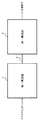
図5は、特許文献1に開示されている2筐体分離型のFPU送信装置の一般的な構成を示すブロック図である。
同図に示すとおり、2筐体分離型FPU送信装置は、送信制御部1aが対象となる映像・音声をIF(Intermediate Frequency:中間周波)信号にデジタル変調し、送信高周波部2aがこのIF信号をSHF(Super High Frequency:センチ波)信号に変換して送信する構成となっている。
具体的には、送信制御部1aでは、入力された映像・音声信号をエンコーダ11aによって符号・圧縮化した後、デジタル変調器12aによってIF信号に変換(デジタル変調)される。
FIG. 5 is a block diagram illustrating a general configuration of a two-case separation type FPU transmission device disclosed in
As shown in the figure, in the two-case separation type FPU transmission apparatus, the transmission control unit 1a digitally modulates the target video / audio into an IF (Intermediate Frequency) signal, and the transmission high-
Specifically, in the transmission control unit 1a, the input video / audio signal is encoded / compressed by the encoder 11a, and then converted into an IF signal (digital modulation) by the
デジタル変調して得られたIF信号は、IF増幅器13aによって所定レベルまで増幅され、分波・合成器14aを通り、同軸ケーブル3aを介して送信高周波部2aに出力される。
送信高周波部2aでは、送信制御部1aからの入力信号が分波・合成器21aによって分波処理され、IF信号が抽出される。
抽出されたIF信号は、IF AGC(Automatic Gain Control:自動利得制御)増幅器22aによって増幅された後、周波数変換器23aによってSHF信号に変換される。
そして、SHF信号は、SHF電力増幅器24aによって所定レベルまで増幅された上で、図示しないFPU受信装置に向け送信されることとなる。
The IF signal obtained by digital modulation is amplified to a predetermined level by the IF amplifier 13a, passes through the demultiplexer /
In the transmission
The extracted IF signal is amplified by an IF AGC (Automatic Gain Control) amplifier 22a and then converted to an SHF signal by a
Then, the SHF signal is amplified to a predetermined level by the
上述のように、FPU送信装置においては、SHF信号を搬送波に利用して無線送信が行われるのが一般的である。
しかし、低C/N(Carrier to Noise Power Ratio:搬送波対雑音電力比)のままSHF信号変換やSHF電力増幅が行われると、サイドローブ特性やIM特性に応じてノイズも増大し伝送品質が悪化することとなる。
そこで、SHF出力を伴うFPU送信装置においては、所定のC/Nが規定され、この規定C/Nを確保することによって一定の伝送品質が保証されるようになっている。
このため、FPU送信装置において高周波部と制御部を接続する同軸ケーブルについても、C/Nすなわち伝送品質を良好にするためには、できる限りケーブル長を短めに設定することが望ましい。
As described above, in an FPU transmission apparatus, radio transmission is generally performed using an SHF signal as a carrier wave.
However, when SHF signal conversion or SHF power amplification is performed with a low C / N (Carrier to Noise Power Ratio), noise increases and transmission quality deteriorates according to sidelobe characteristics and IM characteristics. Will be.
Therefore, in an FPU transmitting apparatus with SHF output, a predetermined C / N is defined, and a certain transmission quality is guaranteed by ensuring this defined C / N.
For this reason, it is desirable to set the cable length as short as possible for the coaxial cable connecting the high-frequency unit and the control unit in the FPU transmission apparatus in order to improve C / N, that is, transmission quality.
しかしながら、特許文献1に記載されているようなFPU送信装置は、その性質上、送信制御部はTV中継車の中や放送局の社屋内などに配置され、送信高周波部はTV中継車のポールの塔頂やビルの屋上などに配置されるのが一般的である。
すなわち、本来、送信制御部と送信高周波部とは相当の距離を経て設置されるものであり、むしろ同軸ケーブルを長く敷設しなければならないことの方が多い。
このため、特許文献1に記載されているようなFPU送信装置において、規定C/Nを考慮せずケーブル長を長くして送信制御部及び送信高周波部を配置すると伝送品質を損ねることとなり、他方、規定C/Nを遵守するためケーブル長を短くすると送信制御部及び送信高周波部の配置場所に苦慮することとなり、二律背反を生ずる問題となっていた。
However, the FPU transmission apparatus as described in
In other words, the transmission control unit and the transmission high-frequency unit are originally installed at a considerable distance, and rather the coaxial cable has to be laid longer.
For this reason, in the FPU transmission apparatus as described in
本発明の目的は、上述した課題である各構成部間のケーブル長の問題と伝送品質の問題とをともに解決する筐体分離型送信装置、高周波装置、送信制御方法及び送信制御プログラムを提供することにある。 An object of the present invention is to provide a case-separated transmission apparatus, a high-frequency apparatus, a transmission control method, and a transmission control program that can solve both the problem of the cable length between components and the problem of transmission quality, which are the problems described above. There is.
上記目的を達成するため、本発明の筐体分離型送信装置は、入力信号をデジタル変調する第一構成部と、前記第一構成部によってデジタル変調された信号を所定信号に変換して外部に送信する第二構成部と、を備え、前記第一構成部と第二構成部とが所定の伝送手段を介して接続される筐体分離型送信装置であって、前記第二構成部が、伝送手段を介して前記第一構成部から入力されたデジタル変調信号をデジタル復調する手段と、前記デジタル復調された信号を再度デジタル変調する手段と、前記デジタル再変調された信号を所定周波数の信号に変換して外部に送信する手段と、を備える構成としてある。 In order to achieve the above object, a case-separated transmission apparatus according to the present invention includes a first component that digitally modulates an input signal, and a signal digitally modulated by the first component that is converted into a predetermined signal to the outside. A second component that transmits, wherein the first component and the second component are connected via a predetermined transmission means, wherein the second component is Means for digitally demodulating the digitally modulated signal input from the first component through the transmission means, means for digitally modulating the digitally demodulated signal again, and converting the digitally remodulated signal to a signal of a predetermined frequency And a means for transmitting the data to the outside after conversion.
また、本発明の高周波装置は、入力信号をデジタル変調する制御装置と所定の伝送手段を介して接続され、そのデジタル変調された信号を所定信号に変換して外部に送信する高周波装置であって、伝送手段を介して前記制御装置からデジタル変調された信号を受信する手段と、受信した前記信号をデジタル復調する手段と、前記デジタル復調された信号を再度デジタル変調する手段と、前記デジタル再変調された信号を所定周波数の信号に変換して外部に送信する手段と、を備える構成としてある。 The high frequency device of the present invention is a high frequency device that is connected to a control device that digitally modulates an input signal via a predetermined transmission means, converts the digitally modulated signal into a predetermined signal, and transmits the signal to the outside. Means for receiving a digitally modulated signal from the control device via a transmission means, means for digitally demodulating the received signal, means for digitally modulating the digitally demodulated signal again, and the digital remodulation Means for converting the converted signal into a signal of a predetermined frequency and transmitting the signal to the outside.
また、本発明の送信制御方法は、入力信号をデジタル変調する第一構成部と、前記第一構成部によってデジタル変調された信号を所定信号に変換して外部に送信する第二構成部と、を備え、前記第一構成部と第二構成部とが所定の伝送手段を介して接続される筐体分離型送信装置における送信制御方法であって、前記第一構成部から、伝送手段を介して前記第二構成部にデジタル変調した前記信号を送信するステップと、前記第二構成部において、伝送手段を介して前記第二構成部に入力されたデジタル変調信号をデジタル復調するステップと、前記デジタル復調された信号を再度デジタル変調するステップと、前記デジタル再変調された信号を所定周波数の信号に変換して外部に送信するステップと、を備える方法としてある。 The transmission control method of the present invention includes a first component that digitally modulates an input signal, a second component that converts the signal digitally modulated by the first component into a predetermined signal, and transmits the signal to the outside. A transmission control method in a case-separated transmission apparatus in which the first component and the second component are connected via a predetermined transmission unit, from the first component via the transmission unit Transmitting the digitally modulated signal to the second component, and digitally demodulating the digital modulated signal input to the second component via the transmission unit in the second component, The method comprises the steps of digitally modulating the digitally demodulated signal again, and converting the digitally remodulated signal into a signal having a predetermined frequency and transmitting the signal to the outside.
さらに、本発明の送信制御プログラムは、入力信号をデジタル変調する第一構成部と、前記第一構成部によってデジタル変調された信号を所定信号に変換して外部に送信する第二構成部と、を備え、前記第一構成部と第二構成部とが所定の伝送手段を介して接続される筐体分離型送信装置における送信制御プログラムであって、前記筐体分離型送信装置を構成するコンピュータを、伝送手段を介して前記第一構成部から入力されたデジタル変調信号をデジタル復調する手段、前記デジタル復調された信号を再度デジタル変調する手段、前記デジタル再変調された信号を所定周波数の信号に変換して外部に送信する手段、として機能させるためのプログラムとしてある。 Furthermore, the transmission control program of the present invention includes a first component that digitally modulates an input signal, a second component that converts the signal digitally modulated by the first component into a predetermined signal, and transmits the signal to the outside. A transmission control program in a case-separated transmission device in which the first component and the second component are connected via a predetermined transmission means, and the computer constituting the case-separated transmission device Means for digitally demodulating the digitally modulated signal input from the first component through the transmission means, means for digitally modulating the digitally demodulated signal again, and converting the digitally remodulated signal to a signal of a predetermined frequency. This is a program for functioning as a means for transmitting to the outside after being converted.
本発明の筐体分離型送信装置によれば、伝送手段を介して接続される各構成部間における所要C/Nが、SHF出力信号の所要C/Nに制限されず、第二構成部で受信される信号の所要C/Nを低く設定することができる。
従って、良好な伝送品質を維持しつつ、各構成部間のケーブル長を従来よりも長く設定することが可能である。
According to the separated case type transmitting apparatus of the present invention, the required C / N between the components connected via the transmission means is not limited to the required C / N of the SHF output signal, and the second component is The required C / N of the received signal can be set low.
Therefore, it is possible to set the cable length between the constituent parts longer than the conventional one while maintaining good transmission quality.
以下、本発明の好ましい実施形態について図1〜図4を参照して説明する。
ここで、以下に示す本発明の一実施形態に係る2筐体分離型デジタルFPU送信装置は、プログラム(ソフトウェア)の命令によりコンピュータで実行される処理,手段,機能によって実現される。プログラムは、コンピュータの各構成要素に指令を送り、以下に示すような所定の処理・機能を行わせる。すなわち、本発明に係る筐体分離型送信装置における各処理・手段は、プログラムとコンピュータとが協働した具体的手段によって実現される。
なお、プログラムの全部又は一部は、例えば、磁気ディスク,光ディスク,半導体メモリ,その他任意のコンピュータで読取り可能な記録媒体により提供され、記録媒体から読み出されたプログラムがコンピュータにインストールされて実行される。また、プログラムは、記録媒体を介さず、通信回線を通じて直接にコンピュータにロードし実行することもできる。
A preferred embodiment of the present invention will be described below with reference to FIGS.
Here, the two-case separated digital FPU transmission apparatus according to an embodiment of the present invention described below is realized by processing, means, and functions executed by a computer in accordance with instructions of a program (software). The program sends a command to each component of the computer to perform predetermined processing and functions as shown below. That is, each processing / means in the case-separated transmission apparatus according to the present invention is realized by specific means in which a program and a computer cooperate.
Note that all or part of the program is provided by, for example, a magnetic disk, optical disk, semiconductor memory, or any other computer-readable recording medium, and the program read from the recording medium is installed in the computer and executed. The The program can also be loaded and executed directly on a computer through a communication line without using a recording medium.
図1は、本発明の筐体分離型送信装置の一実施形態を示すブロック図である。
また、図2は、図1に示す筐体分離型送信装置の一実施形態に係る2筐体分離型デジタルFPU送信装置(以下、FPU送信装置という。)の具体的構成を示すブロック図である。
図1に示す通り、本発明の筐体分離型送信装置は、入力信号をデジタル変調する第一構成部1と、第一構成部1によってデジタル変調された信号を所定信号に変換して外部に送信する第二構成部2とを備えており、第一構成部1と第二構成部2とが所定の伝送手段3を介して接続される構成となっている。
より具体的には、図2に示すとおり、本実施形態に係る筐体分離型送信装置は、2筐体分離型のデジタルFPU送信装置であって、送信制御部(第一構成部)1及び送信高周波部(第二構成部)2、及び送信制御部1と送信高周波部2を接続する同軸ケーブル(伝送手段)3によって構成される。
以下に、本実施形態のFPU送信装置の主な構成部である送信制御部1及び送信高周波部2について詳細に説明する。
FIG. 1 is a block diagram showing an embodiment of a case-separated transmitter according to the present invention.
FIG. 2 is a block diagram showing a specific configuration of a two-case separation type digital FPU transmission device (hereinafter referred to as an FPU transmission device) according to an embodiment of the case separation-type transmission device shown in FIG. .
As shown in FIG. 1, the case-separated transmission apparatus of the present invention includes a
More specifically, as shown in FIG. 2, the case separation type transmission device according to the present embodiment is a two case separation type digital FPU transmission device including a transmission control unit (first component) 1 and A transmission high-frequency unit (second component) 2 and a coaxial cable (transmission means) 3 that connects the
Below, the
[送信制御部1]
送信制御部1は、本発明の第一構成部となるものであって、対象となる入力信号である映像・音声信号をデジタル変調してIF(Intermediate Frequency)信号に変換するものであり、エンコーダ11,デジタル変調器12,IF増幅器13及び分波・合成器14を備えている。
エンコーダ11は、入力した映像・音声信号を符号化・圧縮するものであり、本発明の符号化手段を構成するものである。
具体的には、MPEG−2、H.264等といった各種規格に対応するものとなっている。
[Transmission control unit 1]
The
The encoder 11 encodes and compresses the input video / audio signal and constitutes the encoding means of the present invention.
Specifically, MPEG-2, H.264. It corresponds to various standards such as H.264.
デジタル変調器12は、符号化・圧縮された信号に対してデジタル変調処理を施し、所定のIF信号を得るものであり、本発明の第一変調手段を構成する。
具体的には、OFDM(Orthogonal Frequency Division Multiplexing)、QAM(Quadrature Amplitude Modulation)、QPSK(Quadrature Phase Shift Keying)等の各種デジタル変調方式に対応するものである。
The digital modulator 12 performs digital modulation processing on the encoded / compressed signal to obtain a predetermined IF signal, and constitutes the first modulation means of the present invention.
Specifically, it corresponds to various digital modulation schemes such as OFDM (Orthogonal Division Multiplexing), QAM (Quadrature Amplitude Modulation), QPSK (Quadrature Phase Shift Keying).
IF増幅器13は、デジタル変調器12を通して得た変調後のIF信号を所定レベルまで増幅させるものである。
分波・合成器14は、変調後のIF信号とDC電圧とによって所定の合成信号を生成するものであり、本発明の合成手段を構成する。
なお、分波・合成器14によって生成された合成信号は、同軸ケーブル3を介して送信高周波部2に出力される。
The IF amplifier 13 amplifies the modulated IF signal obtained through the digital modulator 12 to a predetermined level.
The demultiplexer / synthesizer 14 generates a predetermined synthesized signal based on the modulated IF signal and the DC voltage, and constitutes the synthesizing means of the present invention.
The synthesized signal generated by the demultiplexer / synthesizer 14 is output to the transmission high-
[送信高周波部2]
送信高周波部2は、本発明の第二構成部(高周波装置)を構成するものであり、送信制御部2からの変調IF信号をSHF信号に変換した上で、図示しないアンテナを介してFPU受信装置に送信するようになっている。
具体的には、送信高周波部2は、分波・合成器21,IF AGC増幅器22,周波数変換器23,SHF電力増幅器24,デジタル復調器25及びデジタル変調器25を備えている。
分波・合成器21は、送信制御部2からの合成信号を分波してIF信号を抽出するものであり、本発明の分波手段を構成する。
IF AGC増幅器22は、AGC(自動利得調整)機能付きの増幅回路であり、抽出したIF信号を所定レベルまで自動的に増幅するものである。
[Transmission high-frequency unit 2]
The transmission high-
Specifically, the transmission high-
The demultiplexer / synthesizer 21 demultiplexes the combined signal from the
The IF AGC amplifier 22 is an amplifier circuit with an AGC (automatic gain adjustment) function, and automatically amplifies the extracted IF signal to a predetermined level.
デジタル復調器25は、IF AGC増幅器22からのIF信号を一旦デジタル復調し、映像・音声信号に係るデジタルデータを得るものであり、本発明の復調手段を構成する。
デジタル変調器26は、復調された後のデジタルデータを再びデジタル変調してIF信号を得るものであり、本発明の第二変調手段を構成する。
これは、送信高周波部2においてデジタル復調後、再度デジタル変調を行うことによりC/Nを改善することができるようになっている。
The
The digital modulator 26 digitally modulates the demodulated digital data again to obtain an IF signal, and constitutes the second modulation means of the present invention.
This is so that C / N can be improved by performing digital modulation again after digital demodulation in the transmission high-
このように、送信高周波部2においてデジタル復調後、再度デジタル変調を行うことによりC/Nを改善することができ、これによって、送信制御部1と送信高周波部2とを接続する同軸ケーブル3を従来よりも長くすることが可能となっている。
C/Nと同軸ケーブル3のケーブル長の関係については、後に更に詳述する(図4参照)。
In this way, the C / N can be improved by performing digital modulation again after digital demodulation in the transmission high-
The relationship between C / N and the cable length of the
周波数変換器23は、デジタル変調器26によって再変調された後のIF信号をSHF信号に変換するものであり、本発明の周波数変換手段を構成する。
SHF電力増幅器24は、SHF信号を所定レベルまで増幅するものであり、増幅されたSHF信号は図示しないアンテナを介してFPU受信装置に送信されることとなる。
The frequency converter 23 converts the IF signal after being remodulated by the digital modulator 26 into an SHF signal, and constitutes a frequency conversion means of the present invention.
The SHF power amplifier 24 amplifies the SHF signal to a predetermined level, and the amplified SHF signal is transmitted to the FPU receiving apparatus via an antenna (not shown).
次に、以上のような構成からなる本実施形態に係るFPU送信装置におけるC/Nと同軸ケーブル3のケーブル長の関係について、図4に示すグラフ(特性図)を参照しつつ説明する。
図4は、本実施形態に係るFPU送信装置の送信高周波部における到達IF信号レベルとC/Nとの関係(即ち、IF AGC増幅器22の入出力特性)を示した特性図である。
同図において、(1)はSHF出力信号の規定C/N値を示すものであり、(2)はデジタル変調方式の所要C/N値を示すものである。
また、同図において、(b)は(1)に対応する送信高周波部2の到達IF信号レベルであり、(a)は(2)に対応する送信高周波部2の到達IF信号レベルを示したものである。
Next, the relationship between the C / N and the cable length of the
FIG. 4 is a characteristic diagram showing the relationship between the reached IF signal level and the C / N (that is, the input / output characteristics of the IF AGC amplifier 22) in the transmission high-frequency part of the FPU transmission apparatus according to this embodiment.
In the figure, (1) shows the prescribed C / N value of the SHF output signal, and (2) shows the required C / N value of the digital modulation system.
Also, in the figure, (b) shows the arrival IF signal level of the transmission high-
この図に示すように、従来は、SHF信号出力を伴う送信高周波部2における到達IF信号レベルは、少なくとも(b)を確保しなければならず、(a)の到達信号レベルでは伝送品質を確保することができなかった。
しかしながら、本実施形態のように送信高周波部2に到達されたIF信号をデジタル復調し、再度デジタル変調を行うことにより、C/Nが改善されるため、あたかも許容C/Nを拡張できるような効果を得ることができる。
As shown in this figure, conventionally, at least the reached IF signal level in the transmission high-
However, since the C / N is improved by digitally demodulating the IF signal reaching the transmission high-
具体的には、送信高周波部2におけるIF AGC増幅器22の出力側のC/Nは、送信制御部1の出力点におけるC/Nまで改善され、その結果、同軸ケーブル3を介する以前のC/Nに回復されることとなる。
従って、仮に、ケーブル長Xmの同軸ケーブルが接続され、この場合の送信高周波部2への到達IF信号レベルが(a)であったとした場合、対応するC/N(2)は、(3)のレベル、すなわち、同軸ケーブル3を介する以前のレベルまで改善され、規定C/Nを満たすこととなる。
このため、実質的には、(a)の到達信号レベルのXmの同軸ケーブル3を使用できることになり、伝送品質を損なうことなく、同軸ケーブル3のケーブル長を長く確保できることになる。
Specifically, the C / N on the output side of the IF AGC amplifier 22 in the transmission high-
Accordingly, if a coaxial cable having a cable length Xm is connected and the IF signal level reaching the transmission high-
For this reason, the
次に、以上のような構成からなる本実施形態のFPU送信装置における動作手順について図3を参照しながら説明する。
図3は、本実施形態に係るFPU送信装置における動作手順を示したシーケンス図である。
同図に示すように、送信制御部1では、まず、エンコーダ11が、対象となる映像・音声信号を符号・圧縮する(S1)。
次に、デジタル変調器12が、符号・圧縮された信号を所定のIF信号に変調する(S2)。
引き続き、IF増幅器13は、IF信号を所定レベルまで増幅する(S3)。
そして、分波・合成器14は、増幅されたIF信号と所定電圧とを合成し(S4)、同軸ケーブル3を介して送信高周波部2に合成信号を出力する(S5)。
Next, an operation procedure in the FPU transmission apparatus of the present embodiment configured as described above will be described with reference to FIG.
FIG. 3 is a sequence diagram showing an operation procedure in the FPU transmission apparatus according to the present embodiment.
As shown in the figure, in the
Next, the digital modulator 12 modulates the encoded / compressed signal into a predetermined IF signal (S2).
Subsequently, the IF amplifier 13 amplifies the IF signal to a predetermined level (S3).
Then, the demultiplexer / synthesizer 14 synthesizes the amplified IF signal and the predetermined voltage (S4), and outputs the synthesized signal to the transmission high-
これを受け、送信高周波部2では、分波・合成器21が、同軸ケーブル3を介して入力された合成信号を分波して、IF信号を抽出する(S6)。
次に、IF AGC増幅器22が、抽出したIF信号を一定レベルまで増幅する(S7)。
ここで、デジタル復調器25は、IF信号を一旦元のデジタルデータに復調する(S8)。
In response to this, in the transmission high-
Next, the IF AGC amplifier 22 amplifies the extracted IF signal to a certain level (S7).
Here, the
そして、デジタル変調器26によって復調されたデジタルデータを再度デジタル変調し、IF信号を得る(S9)。
次に、周波数変換器23は、デジタル変調によって得たIF信号をSHF信号に変換する(S10)。
最後に、SHF電力増幅器24は、SHF信号を所定レベルまで増幅し(S11)、増幅されたSHF信号は、図示しないアンテナを介してFPU受信装置に出力される(S12)。
Then, the digital data demodulated by the digital modulator 26 is digitally modulated again to obtain an IF signal (S9).
Next, the frequency converter 23 converts the IF signal obtained by digital modulation into an SHF signal (S10).
Finally, the SHF power amplifier 24 amplifies the SHF signal to a predetermined level (S11), and the amplified SHF signal is output to the FPU receiver via an antenna (not shown) (S12).
以上説明したように、本実施形態のFPU送信装置によれば、同軸ケーブル3を介して送信制御部1と送信高周波部2とが接続されており、送信高周波部2にはデジタル復調器25とデジタル変調器26とを新たに搭載するようにしている。
そして、送信高周波部2においては、デジタル復調器25が送信制御部2からのIF信号を一旦デジタルデータにデジタル復調し、引き続きデジタル変調器26がそのデジタルデータをデジタル変調するようにしている。
これにより、C/Nが改善され、送信高周波部2における到達信号レベルが所定値より低くても一定の伝送品質を確保することができる。
すなわち、本実施形態に係るFPU送信装置によれば、映像音声の品質を一定に維持しつつ、各部間を接続するケーブルを従来よりも長く設定することが可能となり、利便性及び信頼性に優れた伝送システムを提供することが可能となる。
As described above, according to the FPU transmission apparatus of the present embodiment, the
In the transmission high-
As a result, the C / N is improved, and a certain transmission quality can be ensured even if the arrival signal level in the transmission high-
That is, according to the FPU transmission device according to the present embodiment, it is possible to set a cable connecting each part longer than before while maintaining the quality of video and audio, and it is excellent in convenience and reliability. It is possible to provide a transmission system.
以上、本発明の筐体分離型送信装置及び分離型送信装置における送信制御方法について、好ましい実施形態を示して説明したが、本発明は、上述した実施形態にのみ限定されるものではなく、本発明の範囲で種々の変更実施が可能であることは言うまでもない。
例えば、本発明の筐体分離型の映像音声送信装置は、デジタルFPU装置に好ましいものであるが、有線・無線を問わず様々なタイプの伝送装置に広範に利用することができる。
このため、拡張性に優れ、ユーザの利用態様に合わせた様々な伝送システムを実現することも可能である。
また、本発明でデジタル変調・復調される入力信号は、上述した映像信号、音声信号に限定されず、どのような信号であっても対象とすることができる。
As described above, the case separation type transmission apparatus and the transmission control method in the separation type transmission apparatus of the present invention have been described with reference to the preferred embodiments. However, the present invention is not limited to the above-described embodiments. It goes without saying that various modifications can be made within the scope of the invention.
For example, the case-separated video / audio transmission device of the present invention is preferable for a digital FPU device, but can be widely used for various types of transmission devices regardless of wired or wireless.
For this reason, it is also possible to realize various transmission systems that are excellent in expandability and are adapted to the usage mode of the user.
In addition, the input signal to be digitally modulated / demodulated in the present invention is not limited to the video signal and the audio signal described above, and any signal can be targeted.
本発明は、2筐体分離型デジタルFPU送信装置に好適に利用することができる。 The present invention can be suitably used for a two-case separation type digital FPU transmission apparatus.
1 送信制御部(第一構成部)
2 送信高周波部(第二構成部)
22 IF AGC増幅器
23 周波数変換器
24 SHF電力増幅器
25 デジタル復調器
26 デジタル変調器
3 同軸ケーブル
1 Transmission control unit (first component)
2 Transmitting high-frequency unit (second component)
22 IF AGC amplifier 23 Frequency converter 24
Claims (7)
前記第一構成部は、
入力信号を符号化する符号化手段と、
符号化された前記入力信号をデジタル変調する第一変調手段と、
前記第一変調手段によってデジタル変調された信号と所定のDC電圧とを合成した合成信号を、前記伝送手段を介して出力する合成手段と、を備え、
前記第二構成部は、
前記伝送手段を介して入力された合成信号からデジタル変調された信号を抽出する分波手段と、
抽出された前記信号をデジタル復調する復調手段と、
前記デジタル復調された信号をデジタル変調する第二変調手段と、
前記第二変調手段によってデジタル変調された信号を所定周波数の信号に変換し外部に送信する周波数変換手段と、を備えた
ことを特徴とする筐体分離型送信装置。 A first component that digitally modulates an input signal; and a second component that converts the signal digitally modulated by the first component into a predetermined signal and transmits the signal to the outside. A casing-separated transmission apparatus in which two components are connected via a predetermined transmission means,
The first component is
Encoding means for encoding an input signal;
First modulation means for digitally modulating the encoded input signal;
A synthesis means for outputting a synthesized signal obtained by synthesizing the signal digitally modulated by the first modulation means and a predetermined DC voltage via the transmission means,
The second component is
A demultiplexing means for extracting a digitally modulated signal from the combined signal input via the transmission means;
Demodulation means for digitally demodulating the extracted signal;
Second modulation means for digitally modulating the digitally demodulated signal;
A case separation type transmission apparatus comprising: frequency conversion means for converting a signal digitally modulated by the second modulation means into a signal having a predetermined frequency and transmitting the signal to the outside .
前記第二変調手段によってデジタル変調された信号をSHF信号に変換して外部に送信する請求項1記載の筐体分離型送信装置。 The case-separated transmission device according to claim 1, wherein the signal digitally modulated by the second modulation means is converted into an SHF signal and transmitted to the outside.
前記符号化手段によって符号化された信号を所定のIF信号に基づきデジタル変調する請求項1又は2記載の筐体分離型送信装置。 The case-separated transmission apparatus according to claim 1 or 2, wherein the signal encoded by the encoding means is digitally modulated based on a predetermined IF signal.
前記復調手段によってデジタル復調された信号を所定のIF信号に基づきデジタル変調する請求項1乃至3のいずれか一項記載の筐体分離型送信装置。 4. The case-separated transmission apparatus according to claim 1, wherein the signal digitally demodulated by the demodulating unit is digitally modulated based on a predetermined IF signal. 5.
前記第一構成部において、 In the first component,
入力信号を符号化する符号化ステップと、 An encoding step for encoding the input signal;
符号化された前記入力信号をデジタル変調する第一変調ステップと、 A first modulation step for digitally modulating the encoded input signal;
前記第一変調ステップにおいてデジタル変調された信号と所定のDC電圧とを合成した合成信号を、前記伝送手段を介して出力する合成ステップと、を有し、 A synthesis step of outputting a synthesized signal obtained by synthesizing the signal digitally modulated in the first modulation step and a predetermined DC voltage via the transmission means;
前記第二構成部において、 In the second component,
前記伝送手段を介して入力された合成信号からデジタル変調された信号を抽出する分波ステップと、 A demultiplexing step of extracting a digitally modulated signal from the combined signal input via the transmission means;
抽出された前記信号をデジタル復調する復調ステップと、 A demodulation step for digitally demodulating the extracted signal;
前記デジタル復調された信号をデジタル変調する第二変調ステップと、 A second modulation step for digitally modulating the digitally demodulated signal;
前記第二変調ステップにおいてデジタル変調された信号を所定周波数の信号に変換し外部に送信する周波数変換ステップと、を有する A frequency conversion step of converting the signal digitally modulated in the second modulation step into a signal of a predetermined frequency and transmitting the signal to the outside.
ことを特徴とする送信制御方法。 The transmission control method characterized by the above-mentioned.
前記第一構成部のコンピュータを、 The first component computer;
入力信号を符号化する符号化手段、 Encoding means for encoding the input signal;
符号化された前記入力信号をデジタル変調する第一変調手段、及び First modulation means for digitally modulating the encoded input signal; and
前記第一変調手段によってデジタル変調された信号と所定のDC電圧とを合成した合成信号を、前記伝送手段を介して出力する合成手段、として機能させ、 A synthesized signal obtained by synthesizing a signal digitally modulated by the first modulating means and a predetermined DC voltage, and functioning as a synthesizing means for outputting via the transmission means;
前記第二構成部のコンピュータを、 The second component computer;
前記伝送手段を介して入力された合成信号からデジタル変調された信号を抽出する分波手段、 A demultiplexing unit for extracting a digitally modulated signal from the combined signal input via the transmission unit;
抽出された前記信号をデジタル復調する復調手段、 Demodulation means for digitally demodulating the extracted signal;
前記デジタル復調された信号をデジタル変調する第二変調手段、及び Second modulation means for digitally modulating the digitally demodulated signal; and
前記第二変調手段によってデジタル変調された信号を所定周波数の信号に変換し外部に送信する周波数変換手段、として機能させる Function as frequency conversion means for converting the signal digitally modulated by the second modulation means into a signal of a predetermined frequency and transmitting it to the outside
ことを特徴とする送信制御プログラム。 A transmission control program characterized by the above.
Priority Applications (1)
| Application Number | Priority Date | Filing Date | Title |
|---|---|---|---|
| JP2008001100A JP5018485B2 (en) | 2008-01-08 | 2008-01-08 | Case-separated transmission apparatus and transmission control method in separation-type transmission apparatus |
Applications Claiming Priority (1)
| Application Number | Priority Date | Filing Date | Title |
|---|---|---|---|
| JP2008001100A JP5018485B2 (en) | 2008-01-08 | 2008-01-08 | Case-separated transmission apparatus and transmission control method in separation-type transmission apparatus |
Publications (2)
| Publication Number | Publication Date |
|---|---|
| JP2009164944A JP2009164944A (en) | 2009-07-23 |
| JP5018485B2 true JP5018485B2 (en) | 2012-09-05 |
Family
ID=40967017
Family Applications (1)
| Application Number | Title | Priority Date | Filing Date |
|---|---|---|---|
| JP2008001100A Active JP5018485B2 (en) | 2008-01-08 | 2008-01-08 | Case-separated transmission apparatus and transmission control method in separation-type transmission apparatus |
Country Status (1)
| Country | Link |
|---|---|
| JP (1) | JP5018485B2 (en) |
Families Citing this family (3)
| Publication number | Priority date | Publication date | Assignee | Title |
|---|---|---|---|---|
| JP2018067799A (en) * | 2016-10-19 | 2018-04-26 | 株式会社東芝 | Wireless communication device and wireless communication method |
| JP7272059B2 (en) * | 2019-03-29 | 2023-05-12 | 日本電気株式会社 | Antenna radio device, system, method and program |
| JP7332514B2 (en) | 2020-03-26 | 2023-08-23 | 株式会社日立国際電気 | transmitter |
Family Cites Families (1)
| Publication number | Priority date | Publication date | Assignee | Title |
|---|---|---|---|---|
| JPH03162022A (en) * | 1989-11-20 | 1991-07-12 | Matsushita Electric Ind Co Ltd | Portable radio equipment |
-
2008
- 2008-01-08 JP JP2008001100A patent/JP5018485B2/en active Active
Also Published As
| Publication number | Publication date |
|---|---|
| JP2009164944A (en) | 2009-07-23 |
Similar Documents
| Publication | Publication Date | Title |
|---|---|---|
| US20040196404A1 (en) | Apparatus for wireless RF transmission of uncompressed HDTV signal | |
| WO2002056486A1 (en) | Receiver apparatus, mobile terminal, and receiving system | |
| US7139319B2 (en) | Wireless RF link for uncompressed transmission of HDTV signals | |
| JP2002084261A (en) | Radio receiving device and method | |
| KR101242510B1 (en) | Satellite broadcasting system and signal receive method thereof | |
| JP5018485B2 (en) | Case-separated transmission apparatus and transmission control method in separation-type transmission apparatus | |
| JP2011514085A (en) | Beam generation system with ground processing and digital transmission | |
| US8804857B2 (en) | Signal processing method for terrestrial repeater | |
| JP3865715B2 (en) | Digital terrestrial television broadcasting transmission apparatus and receiving apparatus | |
| US20130268278A1 (en) | Audio Communication System, An Audio Transmitter and An Audio Receiver | |
| KR101267097B1 (en) | Digital transmission device | |
| US20050012869A1 (en) | Video receiving tuner | |
| JPH10145342A (en) | Transmitter, receiver and transmitter-receiver | |
| JP4216644B2 (en) | Digital broadcast system, broadcast re-transmission device and broadcast reception device | |
| JP6433594B2 (en) | Signal configuration, transmitter and receiver | |
| JP4665685B2 (en) | Two-case separation type FPU receiver, high frequency image output method and program | |
| KR100452630B1 (en) | Digital broadcasting apparatus and method using the multiple transmitter/receiver antenna | |
| JP2019087895A (en) | Broadcast transmission system | |
| KR20040084429A (en) | Gap Filler For Converting Signals Coupled With Satellite Communication System | |
| JP4559037B2 (en) | Transmission / reception terminal device | |
| JP2009152833A (en) | Radio receiver, video display device and receiving level configuration method | |
| KR20170034692A (en) | Broadcating signal processing device and the control method thereof | |
| JPH09298746A (en) | Video data transmitter, receiver and video data transmission reception system | |
| JP2002050993A (en) | Satellite broadcasting system | |
| KR100466069B1 (en) | Digital audio broadcasting transceiver |
Legal Events
| Date | Code | Title | Description |
|---|---|---|---|
| A621 | Written request for application examination |
Free format text: JAPANESE INTERMEDIATE CODE: A621 Effective date: 20101202 |
|
| A977 | Report on retrieval |
Free format text: JAPANESE INTERMEDIATE CODE: A971007 Effective date: 20120227 |
|
| A131 | Notification of reasons for refusal |
Free format text: JAPANESE INTERMEDIATE CODE: A131 Effective date: 20120306 |
|
| A521 | Written amendment |
Free format text: JAPANESE INTERMEDIATE CODE: A523 Effective date: 20120424 |
|
| TRDD | Decision of grant or rejection written | ||
| A01 | Written decision to grant a patent or to grant a registration (utility model) |
Free format text: JAPANESE INTERMEDIATE CODE: A01 Effective date: 20120515 |
|
| A01 | Written decision to grant a patent or to grant a registration (utility model) |
Free format text: JAPANESE INTERMEDIATE CODE: A01 |
|
| A61 | First payment of annual fees (during grant procedure) |
Free format text: JAPANESE INTERMEDIATE CODE: A61 Effective date: 20120528 |
|
| R150 | Certificate of patent or registration of utility model |
Ref document number: 5018485 Country of ref document: JP Free format text: JAPANESE INTERMEDIATE CODE: R150 Free format text: JAPANESE INTERMEDIATE CODE: R150 |
|
| FPAY | Renewal fee payment (event date is renewal date of database) |
Free format text: PAYMENT UNTIL: 20150622 Year of fee payment: 3 |