JP5018362B2 - Ventilation structure and method for forming ventilation structure - Google Patents
Ventilation structure and method for forming ventilation structure Download PDFInfo
- Publication number
- JP5018362B2 JP5018362B2 JP2007235859A JP2007235859A JP5018362B2 JP 5018362 B2 JP5018362 B2 JP 5018362B2 JP 2007235859 A JP2007235859 A JP 2007235859A JP 2007235859 A JP2007235859 A JP 2007235859A JP 5018362 B2 JP5018362 B2 JP 5018362B2
- Authority
- JP
- Japan
- Prior art keywords
- film
- gas permeable
- membrane
- permeable membrane
- base portion
- Prior art date
- Legal status (The legal status is an assumption and is not a legal conclusion. Google has not performed a legal analysis and makes no representation as to the accuracy of the status listed.)
- Active
Links
Images


Classifications
-
- B—PERFORMING OPERATIONS; TRANSPORTING
- B29—WORKING OF PLASTICS; WORKING OF SUBSTANCES IN A PLASTIC STATE IN GENERAL
- B29C—SHAPING OR JOINING OF PLASTICS; SHAPING OF MATERIAL IN A PLASTIC STATE, NOT OTHERWISE PROVIDED FOR; AFTER-TREATMENT OF THE SHAPED PRODUCTS, e.g. REPAIRING
- B29C65/00—Joining or sealing of preformed parts, e.g. welding of plastics materials; Apparatus therefor
- B29C65/02—Joining or sealing of preformed parts, e.g. welding of plastics materials; Apparatus therefor by heating, with or without pressure
- B29C65/18—Joining or sealing of preformed parts, e.g. welding of plastics materials; Apparatus therefor by heating, with or without pressure using heated tools
-
- B—PERFORMING OPERATIONS; TRANSPORTING
- B29—WORKING OF PLASTICS; WORKING OF SUBSTANCES IN A PLASTIC STATE IN GENERAL
- B29C—SHAPING OR JOINING OF PLASTICS; SHAPING OF MATERIAL IN A PLASTIC STATE, NOT OTHERWISE PROVIDED FOR; AFTER-TREATMENT OF THE SHAPED PRODUCTS, e.g. REPAIRING
- B29C65/00—Joining or sealing of preformed parts, e.g. welding of plastics materials; Apparatus therefor
- B29C65/48—Joining or sealing of preformed parts, e.g. welding of plastics materials; Apparatus therefor using adhesives, i.e. using supplementary joining material; solvent bonding
- B29C65/50—Joining or sealing of preformed parts, e.g. welding of plastics materials; Apparatus therefor using adhesives, i.e. using supplementary joining material; solvent bonding using adhesive tape, e.g. thermoplastic tape; using threads or the like
- B29C65/5007—Joining or sealing of preformed parts, e.g. welding of plastics materials; Apparatus therefor using adhesives, i.e. using supplementary joining material; solvent bonding using adhesive tape, e.g. thermoplastic tape; using threads or the like characterised by the structure of said adhesive tape, threads or the like
- B29C65/5021—Joining or sealing of preformed parts, e.g. welding of plastics materials; Apparatus therefor using adhesives, i.e. using supplementary joining material; solvent bonding using adhesive tape, e.g. thermoplastic tape; using threads or the like characterised by the structure of said adhesive tape, threads or the like being multi-layered
-
- B—PERFORMING OPERATIONS; TRANSPORTING
- B29—WORKING OF PLASTICS; WORKING OF SUBSTANCES IN A PLASTIC STATE IN GENERAL
- B29C—SHAPING OR JOINING OF PLASTICS; SHAPING OF MATERIAL IN A PLASTIC STATE, NOT OTHERWISE PROVIDED FOR; AFTER-TREATMENT OF THE SHAPED PRODUCTS, e.g. REPAIRING
- B29C65/00—Joining or sealing of preformed parts, e.g. welding of plastics materials; Apparatus therefor
- B29C65/48—Joining or sealing of preformed parts, e.g. welding of plastics materials; Apparatus therefor using adhesives, i.e. using supplementary joining material; solvent bonding
- B29C65/50—Joining or sealing of preformed parts, e.g. welding of plastics materials; Apparatus therefor using adhesives, i.e. using supplementary joining material; solvent bonding using adhesive tape, e.g. thermoplastic tape; using threads or the like
- B29C65/5042—Joining or sealing of preformed parts, e.g. welding of plastics materials; Apparatus therefor using adhesives, i.e. using supplementary joining material; solvent bonding using adhesive tape, e.g. thermoplastic tape; using threads or the like covering both elements to be joined
-
- B—PERFORMING OPERATIONS; TRANSPORTING
- B29—WORKING OF PLASTICS; WORKING OF SUBSTANCES IN A PLASTIC STATE IN GENERAL
- B29C—SHAPING OR JOINING OF PLASTICS; SHAPING OF MATERIAL IN A PLASTIC STATE, NOT OTHERWISE PROVIDED FOR; AFTER-TREATMENT OF THE SHAPED PRODUCTS, e.g. REPAIRING
- B29C65/00—Joining or sealing of preformed parts, e.g. welding of plastics materials; Apparatus therefor
- B29C65/48—Joining or sealing of preformed parts, e.g. welding of plastics materials; Apparatus therefor using adhesives, i.e. using supplementary joining material; solvent bonding
- B29C65/50—Joining or sealing of preformed parts, e.g. welding of plastics materials; Apparatus therefor using adhesives, i.e. using supplementary joining material; solvent bonding using adhesive tape, e.g. thermoplastic tape; using threads or the like
- B29C65/5064—Joining or sealing of preformed parts, e.g. welding of plastics materials; Apparatus therefor using adhesives, i.e. using supplementary joining material; solvent bonding using adhesive tape, e.g. thermoplastic tape; using threads or the like of particular form, e.g. being C-shaped, T-shaped
- B29C65/5071—Joining or sealing of preformed parts, e.g. welding of plastics materials; Apparatus therefor using adhesives, i.e. using supplementary joining material; solvent bonding using adhesive tape, e.g. thermoplastic tape; using threads or the like of particular form, e.g. being C-shaped, T-shaped and being composed by one single element
-
- B—PERFORMING OPERATIONS; TRANSPORTING
- B29—WORKING OF PLASTICS; WORKING OF SUBSTANCES IN A PLASTIC STATE IN GENERAL
- B29C—SHAPING OR JOINING OF PLASTICS; SHAPING OF MATERIAL IN A PLASTIC STATE, NOT OTHERWISE PROVIDED FOR; AFTER-TREATMENT OF THE SHAPED PRODUCTS, e.g. REPAIRING
- B29C66/00—General aspects of processes or apparatus for joining preformed parts
- B29C66/01—General aspects dealing with the joint area or with the area to be joined
- B29C66/05—Particular design of joint configurations
- B29C66/10—Particular design of joint configurations particular design of the joint cross-sections
- B29C66/12—Joint cross-sections combining only two joint-segments; Tongue and groove joints; Tenon and mortise joints; Stepped joint cross-sections
- B29C66/122—Joint cross-sections combining only two joint-segments, i.e. one of the parts to be joined comprising only two joint-segments in the joint cross-section
- B29C66/1222—Joint cross-sections combining only two joint-segments, i.e. one of the parts to be joined comprising only two joint-segments in the joint cross-section comprising at least a lapped joint-segment
-
- B—PERFORMING OPERATIONS; TRANSPORTING
- B29—WORKING OF PLASTICS; WORKING OF SUBSTANCES IN A PLASTIC STATE IN GENERAL
- B29C—SHAPING OR JOINING OF PLASTICS; SHAPING OF MATERIAL IN A PLASTIC STATE, NOT OTHERWISE PROVIDED FOR; AFTER-TREATMENT OF THE SHAPED PRODUCTS, e.g. REPAIRING
- B29C66/00—General aspects of processes or apparatus for joining preformed parts
- B29C66/01—General aspects dealing with the joint area or with the area to be joined
- B29C66/05—Particular design of joint configurations
- B29C66/10—Particular design of joint configurations particular design of the joint cross-sections
- B29C66/12—Joint cross-sections combining only two joint-segments; Tongue and groove joints; Tenon and mortise joints; Stepped joint cross-sections
- B29C66/122—Joint cross-sections combining only two joint-segments, i.e. one of the parts to be joined comprising only two joint-segments in the joint cross-section
- B29C66/1224—Joint cross-sections combining only two joint-segments, i.e. one of the parts to be joined comprising only two joint-segments in the joint cross-section comprising at least a butt joint-segment
-
- B—PERFORMING OPERATIONS; TRANSPORTING
- B29—WORKING OF PLASTICS; WORKING OF SUBSTANCES IN A PLASTIC STATE IN GENERAL
- B29C—SHAPING OR JOINING OF PLASTICS; SHAPING OF MATERIAL IN A PLASTIC STATE, NOT OTHERWISE PROVIDED FOR; AFTER-TREATMENT OF THE SHAPED PRODUCTS, e.g. REPAIRING
- B29C66/00—General aspects of processes or apparatus for joining preformed parts
- B29C66/01—General aspects dealing with the joint area or with the area to be joined
- B29C66/05—Particular design of joint configurations
- B29C66/10—Particular design of joint configurations particular design of the joint cross-sections
- B29C66/12—Joint cross-sections combining only two joint-segments; Tongue and groove joints; Tenon and mortise joints; Stepped joint cross-sections
- B29C66/124—Tongue and groove joints
- B29C66/1244—Tongue and groove joints characterised by the male part, i.e. the part comprising the tongue
- B29C66/12441—Tongue and groove joints characterised by the male part, i.e. the part comprising the tongue being a single wall
-
- B—PERFORMING OPERATIONS; TRANSPORTING
- B29—WORKING OF PLASTICS; WORKING OF SUBSTANCES IN A PLASTIC STATE IN GENERAL
- B29C—SHAPING OR JOINING OF PLASTICS; SHAPING OF MATERIAL IN A PLASTIC STATE, NOT OTHERWISE PROVIDED FOR; AFTER-TREATMENT OF THE SHAPED PRODUCTS, e.g. REPAIRING
- B29C66/00—General aspects of processes or apparatus for joining preformed parts
- B29C66/01—General aspects dealing with the joint area or with the area to be joined
- B29C66/05—Particular design of joint configurations
- B29C66/10—Particular design of joint configurations particular design of the joint cross-sections
- B29C66/12—Joint cross-sections combining only two joint-segments; Tongue and groove joints; Tenon and mortise joints; Stepped joint cross-sections
- B29C66/124—Tongue and groove joints
- B29C66/1246—Tongue and groove joints characterised by the female part, i.e. the part comprising the groove
- B29C66/12469—Tongue and groove joints characterised by the female part, i.e. the part comprising the groove being asymmetric
-
- B—PERFORMING OPERATIONS; TRANSPORTING
- B29—WORKING OF PLASTICS; WORKING OF SUBSTANCES IN A PLASTIC STATE IN GENERAL
- B29C—SHAPING OR JOINING OF PLASTICS; SHAPING OF MATERIAL IN A PLASTIC STATE, NOT OTHERWISE PROVIDED FOR; AFTER-TREATMENT OF THE SHAPED PRODUCTS, e.g. REPAIRING
- B29C66/00—General aspects of processes or apparatus for joining preformed parts
- B29C66/01—General aspects dealing with the joint area or with the area to be joined
- B29C66/05—Particular design of joint configurations
- B29C66/20—Particular design of joint configurations particular design of the joint lines, e.g. of the weld lines
- B29C66/23—Particular design of joint configurations particular design of the joint lines, e.g. of the weld lines said joint lines being multiple and parallel or being in the form of tessellations
- B29C66/232—Particular design of joint configurations particular design of the joint lines, e.g. of the weld lines said joint lines being multiple and parallel or being in the form of tessellations said joint lines being multiple and parallel, i.e. the joint being formed by several parallel joint lines
-
- B—PERFORMING OPERATIONS; TRANSPORTING
- B29—WORKING OF PLASTICS; WORKING OF SUBSTANCES IN A PLASTIC STATE IN GENERAL
- B29C—SHAPING OR JOINING OF PLASTICS; SHAPING OF MATERIAL IN A PLASTIC STATE, NOT OTHERWISE PROVIDED FOR; AFTER-TREATMENT OF THE SHAPED PRODUCTS, e.g. REPAIRING
- B29C66/00—General aspects of processes or apparatus for joining preformed parts
- B29C66/01—General aspects dealing with the joint area or with the area to be joined
- B29C66/05—Particular design of joint configurations
- B29C66/20—Particular design of joint configurations particular design of the joint lines, e.g. of the weld lines
- B29C66/24—Particular design of joint configurations particular design of the joint lines, e.g. of the weld lines said joint lines being closed or non-straight
- B29C66/242—Particular design of joint configurations particular design of the joint lines, e.g. of the weld lines said joint lines being closed or non-straight said joint lines being closed, i.e. forming closed contours
- B29C66/2422—Particular design of joint configurations particular design of the joint lines, e.g. of the weld lines said joint lines being closed or non-straight said joint lines being closed, i.e. forming closed contours being circular, oval or elliptical
- B29C66/24221—Particular design of joint configurations particular design of the joint lines, e.g. of the weld lines said joint lines being closed or non-straight said joint lines being closed, i.e. forming closed contours being circular, oval or elliptical being circular
-
- B—PERFORMING OPERATIONS; TRANSPORTING
- B29—WORKING OF PLASTICS; WORKING OF SUBSTANCES IN A PLASTIC STATE IN GENERAL
- B29C—SHAPING OR JOINING OF PLASTICS; SHAPING OF MATERIAL IN A PLASTIC STATE, NOT OTHERWISE PROVIDED FOR; AFTER-TREATMENT OF THE SHAPED PRODUCTS, e.g. REPAIRING
- B29C66/00—General aspects of processes or apparatus for joining preformed parts
- B29C66/50—General aspects of joining tubular articles; General aspects of joining long products, i.e. bars or profiled elements; General aspects of joining single elements to tubular articles, hollow articles or bars; General aspects of joining several hollow-preforms to form hollow or tubular articles
- B29C66/51—Joining tubular articles, profiled elements or bars; Joining single elements to tubular articles, hollow articles or bars; Joining several hollow-preforms to form hollow or tubular articles
- B29C66/53—Joining single elements to tubular articles, hollow articles or bars
- B29C66/534—Joining single elements to open ends of tubular or hollow articles or to the ends of bars
- B29C66/5346—Joining single elements to open ends of tubular or hollow articles or to the ends of bars said single elements being substantially flat
-
- B—PERFORMING OPERATIONS; TRANSPORTING
- B29—WORKING OF PLASTICS; WORKING OF SUBSTANCES IN A PLASTIC STATE IN GENERAL
- B29C—SHAPING OR JOINING OF PLASTICS; SHAPING OF MATERIAL IN A PLASTIC STATE, NOT OTHERWISE PROVIDED FOR; AFTER-TREATMENT OF THE SHAPED PRODUCTS, e.g. REPAIRING
- B29C66/00—General aspects of processes or apparatus for joining preformed parts
- B29C66/50—General aspects of joining tubular articles; General aspects of joining long products, i.e. bars or profiled elements; General aspects of joining single elements to tubular articles, hollow articles or bars; General aspects of joining several hollow-preforms to form hollow or tubular articles
- B29C66/61—Joining from or joining on the inside
- B29C66/612—Making circumferential joints
-
- B—PERFORMING OPERATIONS; TRANSPORTING
- B29—WORKING OF PLASTICS; WORKING OF SUBSTANCES IN A PLASTIC STATE IN GENERAL
- B29C—SHAPING OR JOINING OF PLASTICS; SHAPING OF MATERIAL IN A PLASTIC STATE, NOT OTHERWISE PROVIDED FOR; AFTER-TREATMENT OF THE SHAPED PRODUCTS, e.g. REPAIRING
- B29C66/00—General aspects of processes or apparatus for joining preformed parts
- B29C66/70—General aspects of processes or apparatus for joining preformed parts characterised by the composition, physical properties or the structure of the material of the parts to be joined; Joining with non-plastics material
- B29C66/72—General aspects of processes or apparatus for joining preformed parts characterised by the composition, physical properties or the structure of the material of the parts to be joined; Joining with non-plastics material characterised by the structure of the material of the parts to be joined
- B29C66/729—Textile or other fibrous material made from plastics
- B29C66/7294—Non woven mats, e.g. felt
- B29C66/72941—Non woven mats, e.g. felt coated
-
- B—PERFORMING OPERATIONS; TRANSPORTING
- B29—WORKING OF PLASTICS; WORKING OF SUBSTANCES IN A PLASTIC STATE IN GENERAL
- B29C—SHAPING OR JOINING OF PLASTICS; SHAPING OF MATERIAL IN A PLASTIC STATE, NOT OTHERWISE PROVIDED FOR; AFTER-TREATMENT OF THE SHAPED PRODUCTS, e.g. REPAIRING
- B29C66/00—General aspects of processes or apparatus for joining preformed parts
- B29C66/80—General aspects of machine operations or constructions and parts thereof
- B29C66/83—General aspects of machine operations or constructions and parts thereof characterised by the movement of the joining or pressing tools
- B29C66/832—Reciprocating joining or pressing tools
- B29C66/8322—Joining or pressing tools reciprocating along one axis
-
- B—PERFORMING OPERATIONS; TRANSPORTING
- B29—WORKING OF PLASTICS; WORKING OF SUBSTANCES IN A PLASTIC STATE IN GENERAL
- B29C—SHAPING OR JOINING OF PLASTICS; SHAPING OF MATERIAL IN A PLASTIC STATE, NOT OTHERWISE PROVIDED FOR; AFTER-TREATMENT OF THE SHAPED PRODUCTS, e.g. REPAIRING
- B29C66/00—General aspects of processes or apparatus for joining preformed parts
- B29C66/90—Measuring or controlling the joining process
- B29C66/91—Measuring or controlling the joining process by measuring or controlling the temperature, the heat or the thermal flux
- B29C66/919—Measuring or controlling the joining process by measuring or controlling the temperature, the heat or the thermal flux characterised by specific temperature, heat or thermal flux values or ranges
-
- B—PERFORMING OPERATIONS; TRANSPORTING
- B29—WORKING OF PLASTICS; WORKING OF SUBSTANCES IN A PLASTIC STATE IN GENERAL
- B29C—SHAPING OR JOINING OF PLASTICS; SHAPING OF MATERIAL IN A PLASTIC STATE, NOT OTHERWISE PROVIDED FOR; AFTER-TREATMENT OF THE SHAPED PRODUCTS, e.g. REPAIRING
- B29C66/00—General aspects of processes or apparatus for joining preformed parts
- B29C66/90—Measuring or controlling the joining process
- B29C66/94—Measuring or controlling the joining process by measuring or controlling the time
- B29C66/949—Measuring or controlling the joining process by measuring or controlling the time characterised by specific time values or ranges
-
- B—PERFORMING OPERATIONS; TRANSPORTING
- B29—WORKING OF PLASTICS; WORKING OF SUBSTANCES IN A PLASTIC STATE IN GENERAL
- B29L—INDEXING SCHEME ASSOCIATED WITH SUBCLASS B29C, RELATING TO PARTICULAR ARTICLES
- B29L2031/00—Other particular articles
- B29L2031/753—Medical equipment; Accessories therefor
Description
本発明は、医療用管体の経路たとえば薬液チューブに接合されるルアキャップその他の筐体に採用される通気構造および通気形成方法に関し、特に、製造しやすく信頼性の高い通気構造および通気構造形成方法に関する。 TECHNICAL FIELD The present invention relates to a ventilation structure and a ventilation forming method employed in a path of a medical tube, for example, a luer cap joined to a chemical liquid tube and other casings, and more particularly, an easily manufactured and highly reliable ventilation structure and ventilation structure formation. Regarding the method.
従来、医療機器などに用いられるPVC(polyvinyl chloride:ポリ塩化ビニル)チューブは、気泡や異物の除去、チューブ内面の親水化、およびチューブからの溶出物(可塑剤など)の洗浄を目的として、回路全体を液体で充填する必要があり、このとき、回路のエアを抜くために、末端のキャップや三方活栓を開け閉めする等していた。 Conventionally, PVC (polyvinyl chloride) tubes used for medical devices and the like are circuits for the purpose of removing bubbles and foreign substances, making the inner surface of the tube hydrophilic, and cleaning the eluate (plasticizer, etc.) from the tube. It was necessary to fill the whole with a liquid, and at this time, in order to remove air from the circuit, a cap at the end and a three-way stopcock were opened and closed.
しかしながら、従来の技術では以下の問題点があった。
まず、液体充填の際、キャップや三方活栓の開け閉めは手動で行われるため液漏れが生じる可能性があった。これは、外部の雑菌等の混入の可能性も否定できないため、医療現場では特に慎重にならざるを得ず作業性が劣るという問題点があった。また、液体が高価なものである場合や、厳密な量を供給する場合は、このような密閉開放方式は敬遠されるという問題点があった。
However, the conventional technique has the following problems.
First, when filling the liquid, the cap and the three-way stopcock are manually opened and closed, which may cause liquid leakage. This has the problem that workability is inferior because it is impossible to deny the possibility of contamination by external germs and the like, and it has to be particularly cautious in the medical field. In addition, when the liquid is expensive or when a strict amount is supplied, there is a problem that such a hermetic opening method is avoided.
また、多数の個別具体的な医療処置においては、活栓操作箇所も多くその他の作業も重なるため、人的ミス、すなわち、操作忘れの可能性も排除できず、この場合は、除去したいエアが混入したままとなるという問題点があった。 In addition, in many individual specific medical treatments, there are many stopcock operation parts and other operations are overlapped, so it is not possible to eliminate the possibility of human error, that is, forgetting the operation. In this case, air to be removed is mixed. There was a problem that it remained.
これらを解決するものとして、キャップ端部に疎水性通気膜を融着したものが知られている。この疎水性通気膜には、医療分野では撥水性ないし疎水性の高いPTFE(ポリテトラフルオロエチレン)を多孔シートに成型したものが多く用いられ、微細多孔により通気性を確保し、同時にその撥水力により多孔への液体浸入(反対側への液体移動)を禁止する。 In order to solve these problems, a cap having a hydrophobic air-permeable membrane fused to the end portion of the cap is known. In the medical field, this hydrophobic gas permeable membrane is often made by molding PTFE (polytetrafluoroethylene), which has high water repellency or high hydrophobicity, into a porous sheet. This prohibits liquid intrusion into the pores (liquid movement to the opposite side).
ここで、医療用管体の経路に接合されるキャップ等は、接続性、気密性、耐薬性など各種特性を考慮してポリオレフィン製のものが用いられている。ところが、PTFEとポリオレフィンとでは、溶解温度が異なり、また、溶解度パラメータも異なるので単に加熱するだけでは両者は接着しない。よって、従来の疎水性通気膜は、ポリオレフィン不織シートを加熱溶融してPTFE多孔シートの細孔に浸入させてアンカリングした二層膜とし、不織シート側をキャップ等に融着していた。 Here, as the cap or the like to be joined to the path of the medical tubular body, a polyolefin-made cap is used in consideration of various characteristics such as connectivity, airtightness, and chemical resistance. However, PTFE and polyolefin have different melting temperatures and different solubility parameters, so that they are not bonded to each other simply by heating. Therefore, the conventional hydrophobic gas permeable membrane was a two-layer membrane in which the polyolefin nonwoven sheet was heated and melted and permeated into the pores of the PTFE porous sheet to anchor it, and the nonwoven sheet side was fused to a cap or the like. .
しかしながら、不織シート側をキャップに融着するのであっては、その構造上、接合力が弱くなってしまう。たとえば、加熱手段を押し当てる場合にあっては、押し当てる力が弱いと不織シートの構造的な隙間が残存し、側周から液漏れが生じてしまう。反対に、押し当てる力が強いと、接着剤たるべき不織シート部分が散逸し、そもそも接着しないPTFEとキャップとの面接合となって接着力が低下してしまう。実際、このような通気性キャップは、液体充填時には耐水圧性が低く、液漏れが生じたり剥離が生じたりしており、信頼性が高くないという問題点があった。 However, if the nonwoven sheet side is fused to the cap, the bonding force is weak due to the structure. For example, in the case where the heating means is pressed, if the pressing force is weak, a structural gap of the nonwoven sheet remains, and liquid leakage occurs from the side periphery. On the other hand, if the pressing force is strong, the non-woven sheet portion that should be the adhesive is dissipated, and the PTFE that does not adhere to the surface and the cap are joined to each other to reduce the adhesive strength. In fact, such a breathable cap has a problem that its water pressure resistance is low at the time of liquid filling, liquid leakage or peeling occurs, and the reliability is not high.
また、反対に、通気膜であるPTFE側を内側に、ポリオレフィン製の不織布側を外側に載置して、不織布側から金型(加熱手段)を押し当て、不織布のポリオレフィンの一部を溶融させて、キャップとPTFE膜とを接着させようとした場合には、溶解したポリオレフィンが金型に粘着し、通気膜自体がキャップに接着できないか、一時的に接着できた場合でも、加熱手段を離す際に、キャップから通気膜が剥離する等の問題が生じる。 On the other hand, the PTFE side, which is a gas permeable membrane, is placed inside, and the non-woven fabric side made of polyolefin is placed outside, and a mold (heating means) is pressed from the non-woven fabric side to melt part of the non-woven polyolefin. When the cap and the PTFE membrane are to be bonded, the dissolved polyolefin adheres to the mold, and even if the gas permeable membrane itself cannot be bonded to the cap or can be temporarily bonded, the heating means is released. At this time, there arises a problem that the gas permeable membrane is peeled off from the cap.
また、これを受け、新たな素材開発や構造変更をするのは容易ではなく、製造コストも増大してしまう。 In response to this, it is not easy to develop new materials and change the structure, and the manufacturing cost increases.
また、上述の通気性キャップその他の通気能を備える筐体は金型や押出機により一体的に製造される場合が多い。このため、疎水性通気膜は、キャップその他の筐体の外側から後付けで簡便に熱融着できるものでなくては、製品に制約が生じてしまうという問題点もある。 In addition, the above-described air-permeable cap and other housings having air permeability are often manufactured integrally by a mold or an extruder. For this reason, there is a problem that the hydrophobic air-permeable membrane is restricted in the product unless it can be easily heat-sealed from the outside of the cap or other housing by retrofitting.
本発明は上記に鑑みてなされたものであって、通気性を確保しつつ、液漏れも生じない信頼性の高い通気構造を簡便に提供することを目的とする。 The present invention has been made in view of the above, and an object of the present invention is to simply provide a highly reliable ventilation structure that ensures air permeability and does not cause liquid leakage.
上記の目的を達成するために、請求項1に記載の通気構造は、医療用管体の経路に接合されるルアキャップその他の筐体に採用される通気構造であって、通気膜と、通気膜を設ける筐体部分である基体部と、通気膜と基体部の接合を補助する補助フィルム体と、により構成され、基体部は、通気膜により被覆する貫通孔をもった低融点の合成樹脂製であり、通気膜は、撥水性を有する多孔の第1膜に低融点の第2膜を接着した、通気性を有する合成樹脂製の二層膜であり、補助フィルム体は、低融点の第3膜に第3膜より高融点の第4膜を接着した合成樹脂製の二層膜であり、第3膜の内周部と第2膜とが熱融着して通気膜が補助フィルム体に接合されており、第3膜の外周部と基体部とが熱融着して補助フィルム体が基体部に接合されていることを特徴とする。 In order to achieve the above object, a ventilation structure according to claim 1 is a ventilation structure adopted in a luer cap or other housing joined to a path of a medical tubular body, wherein the ventilation film, the ventilation A low melting point synthetic resin having a base part, which is a casing part for providing a film, and an auxiliary film body that assists in joining the gas permeable film and the base part, and the base part has a through-hole covered with the gas permeable film The air-permeable membrane is a two-layer membrane made of a synthetic resin having air permeability, in which a low-melting point second film is bonded to a porous first membrane having water repellency, and the auxiliary film body has a low-melting point. A synthetic resin double-layer film in which a fourth film having a melting point higher than that of the third film is bonded to the third film, and the inner peripheral portion of the third film and the second film are heat-sealed so that the ventilation film is an auxiliary film. The outer peripheral portion of the third film and the base portion are heat-sealed, and the auxiliary film body is joined to the base portion. It is characterized in.
すなわち、請求項1に係る発明は、補助フィルム体により通気膜を熱融着して一体化するとともに、基体部へも熱融着して密着密封でき、これにより、通気性を確保しつつ液漏れも生じない信頼性の高い通気構造を提供可能とする。また、液体側(筐体内部側)に撥水膜(第1膜)が位置するので、水圧がかかっても第1膜と第2膜の接着力が低下して層分離が生じてしまうことがなく、この点からも通気構造の信頼性を高める。 That is, in the invention according to claim 1, the gas permeable membrane is heat-fused and integrated by the auxiliary film body, and can also be heat-sealed to the base portion so as to be tightly sealed, thereby ensuring liquid permeability while ensuring air permeability. It is possible to provide a highly reliable ventilation structure that does not cause leakage. In addition, since the water repellent film (first film) is located on the liquid side (inside the housing), the adhesive force between the first film and the second film is reduced even when water pressure is applied, resulting in layer separation. This also increases the reliability of the ventilation structure.
また、第4膜は、第3膜や基体部または第2膜より高融点としているので、たとえば加熱手段を押しつけて補助フィルム体を熱融着させる場合であっても、適温に制御することにより、加熱手段側へ補助フィルム体が粘着し、浮き上がったり剥離したりするようなことが生じない。すなわち、筐体外側から後付けにより通気構造を簡便に設けることができ、これにより、生産性を向上させることも可能となる。 In addition, since the fourth film has a higher melting point than the third film, the base portion, or the second film, for example, even when the auxiliary film body is heat-sealed by pressing a heating means, by controlling to an appropriate temperature The auxiliary film body sticks to the heating means side and does not float or peel off. That is, the ventilation structure can be easily provided by retrofitting from the outside of the housing, thereby improving the productivity.
なお、本願において、第2膜と第3膜と基体部にいう低融点とは同レベルの融点をいうものとし、第4膜の高融点とはこれらより融点が高いことを意味する。なお、第2膜と第3膜と基体部は、融点も近似し相溶性も高くなるため、これらの組成は同一もしくは近似していることが好ましい。なお、医療用の通気膜は、撥水性を利用したフッ素樹脂が主に用いられ、これは非常に融点が高く、融点の観点からすれば、第1膜>第4膜>(第2膜、第3膜、基体部)となる。よって、第1膜と第2膜とでは融点も大きく異なり溶解度パラメータも近似しないのが通常であるので、接着方式としては、従来技術に示したように第1膜の微細孔を利用して、ここにアンカリングするように不織シートを熱融着する方法が挙げられる。 In the present application, the low melting point in the second film, the third film, and the base portion means the same melting point, and the high melting point in the fourth film means that the melting point is higher than these. Note that the second film, the third film, and the base portion have similar melting points and higher compatibility, so that their compositions are preferably the same or similar. Note that a fluororesin utilizing water repellency is mainly used as a medical breathable film, which has a very high melting point. From the viewpoint of the melting point, the first film> the fourth film> (the second film, (Third film, base portion). Therefore, since the melting points of the first film and the second film are generally different and the solubility parameter is not approximated, the adhesion method is to utilize the micropores of the first film as shown in the prior art. The method of heat-sealing a nonwoven sheet so that it may be anchored here is mentioned.
また、第3膜と第4膜は、たとえば、融点が20℃程度以上好ましくは30℃以上異なる合成樹脂であって近似した溶解度パラメータを有するものであれば、普通に熱融着させたものを用いることができる。なお、本願では、通気膜も補助フィルム体も二層構造であるが、特性ないし機能を損ねないのであれば、二層以上としてもよく、この意味において本願にいう二層構造は二層以上の構成を含むものとする。また、本願では、第1膜と第2膜との「接着」または第3膜と第4膜との「接着」とは、分離しないように物理的または化学的に接着していればその態様に制限はなく、熱融着による接着も当然に含まれる。 The third film and the fourth film are, for example, synthetic resins that have different melting points and higher than about 30 ° C., preferably 30 ° C. or more and have approximate solubility parameters, and those that are normally heat-sealed. Can be used. In the present application, both the gas permeable membrane and the auxiliary film body have a two-layer structure, but may have two or more layers as long as they do not impair the characteristics or functions. In this sense, the two-layer structure referred to in the present application has two or more layers. Includes configuration. In the present application, the “adhesion” between the first film and the second film or the “adhesion” between the third film and the fourth film is an aspect as long as they are physically or chemically bonded so as not to be separated. There is no limitation, and naturally, adhesion by heat fusion is also included.
また、第3膜の内周部とは膜の内側(中心側)部分を意味し、外周部とは内周部より外側にある膜部分を意味する。 Further, the inner peripheral portion of the third film means an inner (center side) portion of the film, and the outer peripheral portion means a film portion outside the inner peripheral portion.
また、請求項2に記載の通気構造は、医療用管体の経路に接合されるルアキャップその他の筐体に採用される通気構造であって、通気膜と、通気膜を設ける筐体部分である基体部と、通気膜と基体部の接合を補助する補助フィルム体と、により構成され、基体部が、通気膜により被覆する貫通孔をもった低融点の合成樹脂製であり、通気膜が、撥水性を有する多孔の第1膜に低融点の第2膜を接着した、通気性を有する合成樹脂製の二層膜であり、補助フィルム体が、低融点の第3膜に第3膜より高融点の第4膜を接着した、通気膜より外形の大きな合成樹脂製の二層膜であり、通気膜が補助フィルム体からはみ出ないように第2膜と第3膜とを熱融着して通気膜が補助フィルム体に接合されており、第3膜の外縁部分と基体部とを熱融着して補助フィルム体が基体部に接合されていることを特徴とする。
The ventilation structure according to
すなわち、請求項2に係る発明は、補助フィルム体により通気膜を熱融着して一体化するとともに、その外側の余白を基体部へ熱融着して密着密封でき、これにより、通気性を確保しつつ液漏れも生じない信頼性の高い通気構造を提供可能とする。また、液体側(筐体内部側)に撥水膜(第1膜)が位置するので、水圧がかかっても第1膜と第2膜の接着力が低下して層分離が生じてしまうことがなく、この点からも通気構造の信頼性を高める。
That is, the invention according to
また、第4膜は、第3膜や基体部または第2膜より高融点としているので、たとえば加熱手段を押しつけて補助フィルム体を熱融着させる場合であっても、適温に制御することにより、加熱手段側へ補助フィルム体が粘着し、浮き上がったり剥離したりするようなことが生じない。すなわち、筐体外側から後付けにより通気構造を簡便に設けることができ、これにより、生産性を向上させることも可能となる。また、補助フィルム体を通気膜より大きくするだけで、「融着しろ」が形成されるため、全体の形状や構成を複雑化することなく簡便に通気構造を形成でき、これによっても生産性を高めることが可能となる。 In addition, since the fourth film has a higher melting point than the third film, the base portion, or the second film, for example, even when the auxiliary film body is heat-sealed by pressing a heating means, by controlling to an appropriate temperature The auxiliary film body sticks to the heating means side and does not float or peel off. That is, the ventilation structure can be easily provided by retrofitting from the outside of the housing, thereby improving the productivity. In addition, simply by making the auxiliary film body larger than the gas permeable membrane, a “welding margin” is formed, so that the air permeable structure can be easily formed without complicating the overall shape and configuration, which also increases productivity. It becomes possible to raise.
なお、第3膜の外縁部分とは、いわば通気膜がかかっていない部分、すなわち「融着しろ」とでもいうべき領域を表し、必ずしも外周円の縁に限定されるものではない。 The outer edge portion of the third film represents a portion where no air permeable film is applied, that is, a region that should be called “fusion”, and is not necessarily limited to the edge of the outer circumferential circle.
また、請求項3に記載の通気構造は、請求項2に記載の通気構造において、貫通孔を中心として基体部表面に補助フィルム体外形と略同形の第1の窪みを設け、通気膜外形と略同形の第2の窪みを第1の窪みの中央部に設けたことを特徴とする。 According to a third aspect of the present invention, in the vent structure according to the second aspect of the present invention, a first depression having substantially the same shape as the auxiliary film body outer shape is provided on the surface of the base portion with the through hole as a center, The second recess having substantially the same shape is provided at the center of the first recess.
すなわち、請求項3に係る発明は、シーリング効果を高める。加えて、段差を設けることにより通気膜がそこに収まり、厚み方向に張力(盛りあがり)が生じない結果、段差を設けず通気膜分の盛りあがりにより補助フィルム体に常に不要な張力がかかっている場合と比較して製品信頼性が向上する。また、製造の際には、位置決めも容易となる。
That is, the invention according to
なお、「略同形」とは、若干の隙間をもたせて補助フィルム体または通気膜がそれぞれ収容される程度の形状を意味する。 The “substantially the same shape” means a shape that can accommodate the auxiliary film body or the gas permeable membrane with a slight gap.
また、請求項4に記載の通気構造は、請求項1、2または3に記載の通気構造において、通気膜が、多孔性PTFEシートにポリオレフィンの不織布を熱融着させたものであることを特徴とする。
The ventilation structure according to claim 4 is the ventilation structure according to
すなわち、請求項4に係る発明は、使用実績もあり化学的にも安定な通気膜を用いて通気構造を形成できる。なお、水圧は厚み方向にかかるので、水圧がかかるほど通気膜の特に不織布製の第2膜が密となり、通気膜と補助フィルム体の気密性が向上し、遮水性、耐水圧性の信頼性が維持される。 That is, the invention according to claim 4 can form a ventilation structure using a gas permeable membrane that has been used and is chemically stable. Since water pressure is applied in the thickness direction, the more the water pressure is applied, the denser the non-woven fabric second membrane, and the airtightness of the air permeable membrane and the auxiliary film body is improved, and the reliability of water shielding and water pressure resistance is improved. Maintained.
また、請求項5に記載の通気構造は、請求項1〜4のいずれか一つに記載の通気構造において、第2膜と第3膜と基体部とをポリオレフィン製としたことを特徴とする。 Further, the ventilation structure according to claim 5 is the ventilation structure according to any one of claims 1 to 4, wherein the second film, the third film, and the base portion are made of polyolefin. .
すなわち、請求項5に係る発明は、従来提供されている部材を用いることができ、素材の変更や、構造や構成の大幅な変更が不要となり、安価に製品を提供可能となる。 That is, the invention according to claim 5 can use the members provided in the past, and it is not necessary to change the material, and to change the structure and configuration, so that the product can be provided at low cost.
なお、本願では、第4膜としては、たとえば、ポリエステル特にPET(ポリエチレンテレフタレート)を挙げることができ、その他、ポリアミド系樹脂であってもよい。第4膜にポリエステル、第3膜にポリオレフィンを用いる場合には、前述のとおり、第4膜の融点が第3膜の融点より20℃程度以上、好ましくは30℃以上高い組合せとなるようにそれぞれを選択する。この他、第1膜としては広くフッ素樹脂を用いることができ、PTFEの他、PFA(テトラフルオロエチレン・パーフルオロアルキルビニルエーテル共重合体)、FEP(テトラフルオロエチレン・ヘキサフルオロプロピレン共重合体)、ETFE(テトラフルオロエチレン・エチレン共重合体)、PVDF(ポリビニリデンフルオライド)、PCTFE(ポリクロロトリフルオロエチレン)、ECTFE(クロロトリフルオエチレン・エチレン共重合体)を挙げることができる。ポリオレフィンにおいて、加工性、強度、医療用としての使用実績の点から、実質的に選択される材質として、たとえば、PP(ポリプロピレン)やPE(ポリエチレン)を挙げることができる。 In the present application, examples of the fourth film include polyester, particularly PET (polyethylene terephthalate), and may be a polyamide-based resin. When using polyester for the fourth film and polyolefin for the third film, as described above, the melting point of the fourth film is about 20 ° C. or more, preferably 30 ° C. or more higher than the melting point of the third film. Select. In addition, a fluorine resin can be widely used as the first film. In addition to PTFE, PFA (tetrafluoroethylene / perfluoroalkyl vinyl ether copolymer), FEP (tetrafluoroethylene / hexafluoropropylene copolymer), Examples include ETFE (tetrafluoroethylene / ethylene copolymer), PVDF (polyvinylidene fluoride), PCTFE (polychlorotrifluoroethylene), and ECTFE (chlorotrifluoroethylene / ethylene copolymer). In polyolefins, examples of materials that are substantially selected from the viewpoint of processability, strength, and medical use results include PP (polypropylene) and PE (polyethylene).
また、請求項6に記載の通気構造は、請求項1〜5のいずれか一つに記載の通気構造において、補助フィルム体を、その中央部に通気膜の外形より小さな形状の孔を打ち抜いて形成したことを特徴とする。 Further, the ventilation structure according to claim 6 is the ventilation structure according to any one of claims 1 to 5, wherein the auxiliary film body is punched with a hole having a shape smaller than the outer shape of the ventilation film at the center. It is formed.
すなわち、請求項6に係る発明は、通気性のない補助フィルム体をドーナツ形状(環形状)にすることにより、気密性を確保しつつ簡便に通気性も確保し、シーリング効果も向上させる。 That is, in the invention according to claim 6, by making the auxiliary film body without air permeability into a donut shape (annular shape), air permeability is easily ensured while airtightness is ensured, and a sealing effect is also improved.
また、請求項7に記載の通気構造形成方法は、撥水性を有する多孔の第1膜に低融点の第2膜を接着した、通気性を有する合成樹脂製二層膜である通気膜と、通気膜により被覆する貫通孔をあけた筐体部分である低融点の合成樹脂製の基体部と、低融点の第3膜に第3膜より高融点の第4膜を接着した、通気膜と基体部の接合を補助し通気膜より外形の大きな合成樹脂製二層膜である補助フィルム体とにより構成され、医療用管体の経路に接合されるルアキャップその他の筐体に採用される通気構造の形成方法であって、貫通孔に通気膜の第1膜側をあてがい、この上に補助フィルム体の第4膜側が上にくるようにかつ通気膜が補助フィルム体からはみ出ないようにあてがい、筐体外側から加熱手段を押し当てて、第2膜と第3膜とを、および、第3膜と基体部とを熱融着することを特徴とする。 In addition, the air-permeable structure forming method according to claim 7 is a gas-permeable membrane that is a gas-permeable synthetic resin bilayer film in which a low-melting-point second film is bonded to a water-repellent porous first film; A base portion made of a synthetic resin having a low melting point, which is a casing portion having a through-hole covered with a gas permeable membrane, and a gas permeable membrane in which a fourth film having a higher melting point than the third film is bonded to a third film having a low melting point; Ventilation that is used for luer caps and other housings that are composed of a synthetic resin bilayer membrane that assists the bonding of the base portion and has a larger outer shape than the ventilation membrane, and is joined to the path of the medical tube. A method of forming a structure, wherein the first membrane side of the gas permeable membrane is applied to the through-hole, and the fourth membrane side of the auxiliary film body is placed thereon so that the gas permeable membrane does not protrude from the auxiliary film body. Then, the heating means is pressed from the outside of the housing, and the second film and the third film are , Wherein the heat-sealing a third film and the base portion.
すなわち、請求項7に係る発明は、補助フィルム体により通気膜を覆って熱融着により一体化し、また、補助フィルム体の余白を基体部へ熱融着して密着密封でき、通気性を確保しつつ液漏れも生じない信頼性の高い通気構造を提供可能とする。また、液体側(筐体内部側)に撥水膜(第1膜)が位置するので、水圧がかかっても第1膜と第2膜の接着力が低下して層分離が生じてしまうことがなく、この点からも通気構造の信頼性を高める。 That is, the invention according to claim 7 covers the gas permeable membrane with the auxiliary film body and is integrated by heat fusion, and the margin of the auxiliary film body can be heat-sealed to the base portion so as to be tightly sealed, ensuring air permeability. However, it is possible to provide a highly reliable ventilation structure that does not cause liquid leakage. In addition, since the water repellent film (first film) is located on the liquid side (inside the housing), the adhesive force between the first film and the second film is reduced even when water pressure is applied, resulting in layer separation. This also increases the reliability of the ventilation structure.
また、第4膜は、第3膜や基体部または第2膜より高融点としているので、適温に制御することにより、加熱手段側へ補助フィルム体が粘着し、浮き上がったり剥離したりするようなことが生じず、歩留りが高くかつ接合信頼性(耐圧信頼性)の高い通気構造を形成可能となる。筐体外側から後付けにより通気構造を簡便に形成でき、これにより、生産性を向上させることも可能となる。 Further, since the fourth film has a higher melting point than the third film, the base portion, or the second film, the auxiliary film body sticks to the heating means side by controlling to an appropriate temperature, and the fourth film floats up or peels off. Therefore, it is possible to form a ventilation structure having a high yield and high bonding reliability (pressure-resistant reliability). The ventilation structure can be easily formed by retrofitting from the outside of the housing, thereby improving the productivity.
また、請求項8に記載の通気構造形成方法は、請求項7に記載の通気構造形成方法において、貫通孔を中心として基体部表面に補助フィルム体外形と略同形の第1の窪みを設けるとともに、通気膜外形と略同形の第2の窪みを第1の窪みの中央部に設けておき、第2の窪みに通気膜を第1膜側が下にくるように載置し、第1の窪みに補助フィルム体を第4膜側が上にくるように載置し、第4膜側から加熱手段を押し当てて、第2膜と第3膜とを、および、第3膜と基体部とを熱融着することを特徴とする。 According to an eighth aspect of the present invention, there is provided the ventilation structure forming method according to the seventh aspect, wherein the first recess having substantially the same shape as the auxiliary film body outer shape is provided on the surface of the base portion around the through hole. A second recess having substantially the same shape as the outer shape of the gas permeable membrane is provided in the center of the first dent, and the gas permeable membrane is placed in the second dent so that the first membrane side is positioned downward. The auxiliary film body is placed so that the fourth film side is on the upper side, and the heating means is pressed from the fourth film side to bond the second film and the third film, and the third film and the base portion. It is characterized by heat fusion.
すなわち、請求項8に係る発明は、通気膜と補助フィルム体の位置決めを容易とし、生産性を高める。また、通気膜と補助フィルム体のずれを防止するので歩留りも高めることが可能となる。更に、シーリング効果も向上する。 That is, the invention according to claim 8 facilitates the positioning of the gas permeable membrane and the auxiliary film body, and increases the productivity. Moreover, since the gap between the gas permeable membrane and the auxiliary film body is prevented, the yield can be increased. Further, the sealing effect is improved.
また、請求項9に記載の通気構造形成方法は、請求項7または8に記載の通気構造形成方法において、第3膜と基体部をはじめに熱融着し、次いで、第2膜と第3膜を熱融着することを特徴とする。 According to a ninth aspect of the present invention, there is provided the vent structure forming method according to the seventh or eighth aspect, wherein the third film and the base portion are heat-sealed first, and then the second film and the third film. Is heat-sealed.
すなわち、請求項9に係る発明は、外側から熱融着することにより融着の際の膨張やシート変形や浮きを規制して外側も内側も確実に熱融着でき、これにより、信頼性を向上させることが可能となる。 That is, the invention according to claim 9 is capable of reliably heat-sealing both the inside and outside by restricting expansion and sheet deformation and floating during fusion by heat-sealing from the outside, thereby improving reliability. It becomes possible to improve.
また、請求項10に記載の通気構造形成方法は、撥水性を有する多孔の第1膜に低融点の第2膜を接着した、通気性を有する合成樹脂製二層膜である通気膜と、通気膜により被覆する貫通孔をあけた筐体部分である低融点の合成樹脂製の基体部と、低融点の第3膜に第3膜より高融点の第4膜を接着した、通気膜と基体部の接合を補助し通気膜より外形の大きな合成樹脂製二層膜である補助フィルム体とにより構成され、医療用管体の経路に接合されるルアキャップその他の筐体に採用される通気構造の形成方法であって、通気膜の第2膜と補助フィルム体の第3膜を通気膜が補助フィルム体からはみ出ないように接着したものの第1膜側を貫通孔にあてがい、筐体外側から加熱手段を押し当てて、第3膜と基体部とを熱融着することを特徴とする。 The method for forming an air-permeable structure according to claim 10, wherein the air-permeable membrane is a gas-permeable synthetic resin bilayer film in which a low-melting-point second film is bonded to a water-repellent porous first film; A base portion made of a synthetic resin having a low melting point, which is a casing portion having a through-hole covered with a gas permeable membrane, and a gas permeable membrane in which a fourth film having a higher melting point than the third film is bonded to a third film having a low melting point; Ventilation that is used for luer caps and other housings that are composed of a synthetic resin bilayer membrane that assists the bonding of the base portion and has a larger outer shape than the ventilation membrane, and is joined to the path of the medical tube. A method of forming a structure, wherein a second film of a gas permeable membrane and a third film of an auxiliary film body are bonded so that the gas permeable film does not protrude from the auxiliary film body, and the first film side is applied to the through-hole, The heating means is pressed against the third film, and the third film and the base portion are thermally fused. To.
すなわち、請求項10に係る発明は、通気膜を一体化した補助フィルム体の外縁の余白を利用して基体部との密着密封化が可能となり、これにより、通気性を確保しつつ液漏れも生じない信頼性の高い通気構造が提供可能となる。また、液体側(筐体内部側)に撥水膜(第1膜)が位置するので、水圧がかかっても第1膜と第2膜の接着力が低下して層分離が生じてしまうことがなく、この点からも通気構造の信頼性を高める。 That is, the invention according to claim 10 makes it possible to tightly seal with the base body by utilizing the margin of the outer edge of the auxiliary film body integrated with the gas permeable membrane, thereby preventing liquid leakage while ensuring air permeability. A highly reliable ventilation structure that does not occur can be provided. In addition, since the water repellent film (first film) is located on the liquid side (inside the housing), the adhesive force between the first film and the second film is reduced even when water pressure is applied, resulting in layer separation. This also increases the reliability of the ventilation structure.
また、第4膜は、第3膜や基体部または第2膜より高融点としているので、適温で制御することにより、加熱手段側へ補助フィルム体が粘着し、浮き上がったり剥離したりするようなことが生じず、歩留りが高くかつ接合信頼性(耐圧信頼性)の高い通気構造を形成可能となる。筐体外側から後付けにより通気構造を簡便に形成でき、これにより、生産性を向上させることも可能となる。 Further, since the fourth film has a higher melting point than the third film, the base portion, or the second film, the auxiliary film body sticks to the heating means side and is lifted or peeled off by controlling at an appropriate temperature. Therefore, it is possible to form a ventilation structure having a high yield and high bonding reliability (pressure-resistant reliability). The ventilation structure can be easily formed by retrofitting from the outside of the housing, thereby improving the productivity.
また、請求項11に記載の通気構造形成方法は、請求項10に記載の通気構造形成方法において、貫通孔を中心として基体部表面に補助フィルム体外形と略同形の窪みを設けておき、この窪みに第4膜側が上にくるように載置し、第4膜側から加熱手段を押し当てて第3膜と基体部とを熱融着することを特徴とする。
The ventilation structure forming method according to
すなわち、請求項11に係る発明は、補助フィルム体の位置決めを容易とし、生産性を高める。また、補助フィルム体のずれを防止するので歩留りも高めることが可能となる。更に、シーリング効果も向上する。
That is, the invention according to
また、請求項12に記載の通気構造形成方法は、請求項11に記載の通気構造形成方法において、前記窪みの中に更に通気膜外形と略同形の第2の窪みを当該第2の窪みの中心に前記貫通孔が位置するように設けておき、第2の窪みに第1膜側が下にくるように載置し、第4膜側から加熱手段を押し当てて第3膜と基体部とを熱融着することを特徴とする。
A vent structure forming method according to
すなわち、請求項12に係る発明は、補助フィルム体の位置決めを容易とし、生産性を高める。また、補助フィルム体の浮きを防止するので歩留りも高めることが可能となる。更に、シーリング効果もより向上する。
That is, the invention according to
また、請求項13に記載の通気構造形成方法は、請求項7〜12のいずれか一つに記載の通気構造形成方法において、通気膜が、多孔性PTFEシートにポリオレフィンの不織布を熱融着させたものであることを特徴とする。
The method for forming an air-permeable structure according to
すなわち、請求項13に係る発明は、使用実績もあり化学的にも安定な通気膜を用いて通気構造を形成できる。なお、水圧は厚み方向にかかるので、水圧がかかるほど通気膜の特に不織布製の第2膜が密となり、通気膜と補助フィルム体の気密性が向上し、遮水性、耐水圧性の信頼性が維持される。 That is, the invention according to claim 13 can form a ventilation structure using a gas permeable membrane that has been used and is chemically stable. Since water pressure is applied in the thickness direction, the more the water pressure is applied, the denser the non-woven fabric second membrane, and the airtightness of the air permeable membrane and the auxiliary film body is improved, and the reliability of water shielding and water pressure resistance is improved. Maintained.
また、請求項14に記載の通気構造形成方法は、請求項7〜13のいずれか一つに記載の通気構造形成方法において、第2膜と第3膜と基体部とをポリオレフィン製としたことを特徴とする。
In addition, the ventilation structure forming method according to
すなわち、請求項14に係る発明は、従来提供されている部材を用いることができ、素材の変更や構造や構成の大幅な変更が不要となり、安価に製品を提供可能となる。 That is, the invention according to claim 14 can use the members that have been provided conventionally, and it is not necessary to change the material or to change the structure or configuration, so that the product can be provided at low cost.
本発明によれば、通気性を確保しつつ、液漏れも生じない信頼性の高い通気構造を簡便に提供することが可能となる。よって装着するだけでプライミング(エア抜き)が可能となる。また、筐体外側から後付けにより通気構造を簡便に設けることができ、これにより、生産性を向上させることも可能となる。 ADVANTAGE OF THE INVENTION According to this invention, it becomes possible to provide easily the reliable ventilation structure which does not produce a liquid leak, ensuring air permeability. Therefore, it is possible to perform priming (air bleeding) simply by mounting. In addition, a ventilation structure can be easily provided by retrofitting from the outside of the housing, thereby improving productivity.
以下、本発明の実施の形態を図面を参照しながら詳細に説明する。ここでは、本発明をルアキャップに適用し、端面に通気構造を形成する場合について説明する。 Hereinafter, embodiments of the present invention will be described in detail with reference to the drawings. Here, a case where the present invention is applied to a luer cap and a ventilation structure is formed on an end surface will be described.
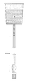
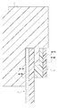
図1は、本実施の形態のルアキャップの断面図である。図2は、接合部分の拡大模式図である。図3は、実際の熱融着の様子を示した概念図である。図4は、本実施の形態のルアキャップの補助フィルム体の融着の様子を示した平面図である。 FIG. 1 is a cross-sectional view of the luer cap of the present embodiment. FIG. 2 is an enlarged schematic view of a joint portion. FIG. 3 is a conceptual diagram showing a state of actual heat fusion. FIG. 4 is a plan view showing a state of fusion of the auxiliary film body of the lure cap of the present embodiment.
通気構造は、ルアキャップ1の後端部に通気膜2と補助フィルム体3とが順に位置し、通気膜2と補助フィルム体3とが熱融着し、かつ、補助フィルム体3とルアキャップ1後端面とが熱融着したものである。
In the ventilation structure, the
ルアキャップ1は、ポリオレフィン製であり、ここではPP製のものを用いている。断面図から明らかなように、このルアキャップ1には貫通孔11が中心に設けられており、キャップ端部には円形の窪み12と、その内側に更に円形の窪み13が設けられている。すなわち、ルアキャップ1後端面は、1段目の円形窪み12の中に2段目の円形窪み13が階段状に設けてあり、円形窪み12および円形窪み13の中心が貫通孔11の中心と重なるように形成されている。ルアキャップ1には、また、内面にねじ14が切ってあり、たとえば図示しない三方活栓に螺合する形状となっている。
The luer cap 1 is made of polyolefin, and here is made of PP. As apparent from the cross-sectional view, the luer cap 1 is provided with a through
通気膜2は、円形窪み13より若干径の小さな円形シートであり、微細多孔通気シートとして形成してあるフッ素樹脂製(ここではPTFE製)の第1膜21と、不織シートとして形成してあるポリオレフィン製(ここではPP製)の第2膜22と、を熱融着し、通気性と遮水性、ならびに、補助フィルム体3への接着性を確保した二層膜である。通気性と遮水性に関しては、微細孔構造によって通気性をもたせつつPTFEの高撥水性により液体浸入を防止し遮水性を確保している。ここで、PTFEは高融点であり反対にPPは低融点であって相溶性も高くない。従って、化学的には接着しにくいので、PPを熱溶融してPTFE微細孔に浸入させ、アンカリングにより物理的に両者を貼着するようにしている。また、PPはそのままでは通気性がないため、不織シートに成型して第2膜22自体の通気性を確保している。
The gas
より具体的には、通気膜2は、たとえば以下の方法により製造できる。まず、PTFEパウダー100gと、液状潤滑剤として26gのソルベントナフサを混合する。この混合物を圧力50kg/cm2で加圧予備成形後、ペースト押出機により押し出し、圧延により所望の厚み、たとえば、0.3mm厚のシート状にする。これを200℃の加熱ロールに沿わせて加熱乾燥し、ソルベントナフサを除去する。
More specifically, the gas
次いで、約275℃に加熱したロール型延伸機で一軸方向(長手方向)に100%延伸し、更に約150℃に加熱したロール型延伸機で同方向に200%延伸する。この延伸シートを延伸した状態のまま、約400℃で5分間加熱して焼結することによって多孔性PTFEシートを得ることができる。最後に、PP製不織布とこのPTFEシートとを、所定温度で融着(ラミネート)する。最後に、円形窪み13より若干径の小さな円形シートとなるように、ラミネートシートを打ち抜く。これにより、通気性と遮水性を有する通気膜2が形成される。
Next, the film is stretched 100% in a uniaxial direction (longitudinal direction) with a roll-type stretching machine heated to about 275 ° C., and further stretched 200% in the same direction with a roll-type stretching machine heated to about 150 ° C. A porous PTFE sheet can be obtained by heating and sintering at about 400 ° C. for 5 minutes while the stretched sheet is stretched. Finally, the PP nonwoven fabric and this PTFE sheet are fused (laminated) at a predetermined temperature. Finally, the laminate sheet is punched out so that a circular sheet having a slightly smaller diameter than the
補助フィルム体3は、円形窪み12より若干径の小さな円形シートから中心部を打ち抜いたドーナツ形状の二層膜である。ここで、打ち抜く内円は通気膜2の円より小さくして、補助フィルム体3と通気膜2との接合部分を確保する。また、打ち抜くことにより通気性を確保する。二層膜は、片面をポリオレフィン製(ここではPP製)とし、他面をポリエステル製(ここではPET製)とする。以降において便宜上前者を第3膜31、後者を第4膜32とする。また、打ち抜いた円部分を打ち抜き孔33とする。PPとPETは、常法、たとえば、ドライラミネート法(希釈した接着剤をフィルムに塗布し、巻取りにより2枚のフィルムを貼り合わせる方法)により貼着が可能である。
The
なお、膜の厚みに特に限定はないが、通気膜2の厚みは、たとえば0.15mm〜0.35mmとすることができ、また、補助フィルム体3の厚みは、たとえば、0.10mm〜0.30mmとすることができる。なお、ルアキャップ1の外径は約10mmであり、貫通孔11の径は約1.5mmであるので、通気膜2の直径は3.0mm〜6.5mm、補助フィルム体3の外径は7.5mm〜9.5mm、内径は1.0mm〜3.5mmとすることができる。
The thickness of the membrane is not particularly limited, but the thickness of the gas
また、補助フィルム体3の外半径、通気膜2の半径、補助フィルム体3の内半径を、それぞれr3,r2,r1とすると、通気性の観点から、r3:r1=6:1〜2:1が好ましく、熱融着の面積の観点から、(r3−r2):(r2−r1)=2:1〜1:2が好ましい。なお、熱融着の幅は、1mm以上であることが好ましい(図4参照)。また、製造上の観点からは、r3:r2=5:1〜5:3、r2:r1=7:1〜7:3が好ましい。
Further, assuming that the outer radius of the
<製造例1>
次に、円形の通気膜2と、これより外径は大きく内径は小さなドーナツ型の補助フィルム体3と、ルアキャップ1との接合方法について説明する。製造例1では、通気膜2と、補助フィルム体3と、をルアキャップ1後端に別々に載置した後、熱融着する態様について説明する。なお、以下の例では、工業的生産工程における量産ラインについて必要箇所部分のみ説明する。
<Production Example 1>
Next, a method for joining the circular air-
まず、ルアキャップ1を、後端部を上に向け順次整列させる。これは、アームにより保持してもよいし、ルアキャップ1の外形と略同型の嵌合穴に埋め込み、固定する方法が挙げられる。次いで、通気膜2を、第1膜21を下にして、円形窪み13に載置する。これは、ラミネートシートから通気膜2を打ち抜いたものを陰圧により吸い付けて移動し静置する方法が挙げられる。これにより、通気膜2の表裏の判別制御が不要となる。また、打ち抜き金型により一度に多量の通気膜2が形成されるので、金型の穴の数だけ吸引アームを設けておき量産に対応させるようにしてもよい。
First, the luer caps 1 are sequentially aligned with the rear end portion facing up. This may be held by an arm, or may be embedded and fixed in a fitting hole having substantially the same shape as the outer shape of the luer cap 1. Next, the gas
次に、補助フィルム体3を、第3膜31を下にして円形窪み12に載置する。これにより通気膜2が補助フィルム体3により覆われる。なお、補助フィルム体3も通気膜2の載置と同様な方式を用い、吸引アームによる打ち抜き直後の表裏の区別がついた二層膜を、正しい向きで載置可能となる。
Next, the
つづいて、補助フィルム体3を円形窪み12へ熱融着する。補助フィルム体3の第3膜31も円形窪み12も共にPP製であるため、両者は容易に密に接着する。加熱に際しては、補助フィルム体3の外円よりやや小さな円筒形ヒータ(溶着金型)を短時間、たとえば、145℃×3秒、円形窪み12に挿入するようにして押し当てる。ここで、ヒータ側の第4膜32はPET製なので、ヒータに溶着せず、ヒータを引き上げる際に補助フィルム体3が浮きあがったり、ヒータ側に持っていかれたりするようなことが生じず、強固な接着を実現する。
Subsequently, the
次に、通気膜2と補助フィルム体3とを熱融着する。通気膜2の第2膜22も補助フィルム体3の第3膜31も共にPP製であるため、両者は容易に密に接着する。加熱に際しては、通気膜2の径よりやや小さな円筒形ヒータを短時間、たとえば、145℃×3秒、円形窪み13に挿入するようにして押し当てる。ここで、不織シートである第2膜22は、第1膜21との接合面の反対側から溶融するので、第1膜21と第2膜22との接合力を損ねず密に通気膜2と補助フィルム体3とを融着できる。
Next, the gas
最後にルアキャップ1の固定を取り除く。順次以上の作業を繰り返すことにより、目的の通気構造の形成されたルアキャップを得ることができる。 Finally, remove the luer cap 1. By repeating the above operations in sequence, a luer cap in which the target ventilation structure is formed can be obtained.
なお、図1に示した領域Aは、PPの溶融により通気膜2を側周からパッキングないしシーリングされることとなり、遮水性も更に向上する(図3参照)。
In the region A shown in FIG. 1, the gas
以上の例では、外周側の次に内周側を熱融着する態様を説明した。これは、内周側を先に熱融着すると加熱や押しつけにより膜が上へ浮き上がるように変形し、緩みやたるみが生じ、外周側の熱融着が安定化せず均一な熱融着とならない可能性があるためである。なお、制御によっては、内周側の次に外周側を熱融着する態様であってもよい。なお、径の異なる二つのヒータを別々に用いる例を示したが、二重円筒ヒータを用いて、一気に両者を熱融着させるようにしてもよい。 In the above example, the aspect in which the inner peripheral side is heat-sealed next to the outer peripheral side has been described. This is because if the inner peripheral side is heat-sealed first, the film is deformed so that it is lifted up by heating or pressing, loosening or sagging occurs, and the heat fusion on the outer peripheral side is not stabilized and uniform heat-sealing. This is because there is a possibility of not becoming. Depending on the control, the outer peripheral side may be heat-sealed next to the inner peripheral side. In addition, although the example which uses two heaters from which a diameter differs separately was shown, you may make it heat-seal both at once using a double cylinder heater.
<製造例2>
次に、円形の通気膜2と、これより外径は大きく内径は小さなドーナツ型の補助フィルム体3と、を予め熱融着したものをルアキャップに載置し、これを熱融着する態様について説明する。なお、以下の例では、工業的生産工程における量産ラインについて必要箇所部分のみ説明する。
<Production Example 2>
Next, a circular air-
まず、事前に、通気膜2が熱融着した補助フィルム体の半製品を準備しておく。たとえば、第1膜と第2膜が熱融着したラミネートシートを、第2膜側を上にし、打ち抜き型枠を用いて円形窪み13より若干小さな径の円を整然と打ち抜き、この打ち抜いた円板シート(通気膜2)がそのまま台座に残るようにする。
First, a semi-finished product of an auxiliary film body in which the gas
次に、この整然と配列した円形の通気膜2に、第3膜と第4膜との二層膜シートを、第3膜側が下になるように被覆し、打ち抜き孔33より径の大きな円筒形ヒータを通気膜2と同一中心となるように押し当てて、シートに水玉のように通気膜2が多数熱融着した半製品を用意しておく。なお、第3膜と第4膜とが接合した二層膜シートには、台座上に整然と配列した円形の通気膜2のそれぞれの中心に重なるように、予め打ち抜き孔33をあけておく。
Next, the circular gas
なお、円筒形ヒータは第4膜側から押し当てるようにする。通気膜2の第2膜22も補助フィルム体3の第3膜31も共にPP製であるため、両者は容易に密に接着する。
The cylindrical heater is pressed from the fourth film side. Since both the
製造に際しては、まず、ルアキャップ1後端部を上に向け順次整列させる。これは、アームにより保持してもよいし、ルアキャップ1の外形と略同型の嵌合穴に埋め込み、固定する方法が挙げられる。次いで、通気膜2が熱融着した補助フィルム体3を、第1膜21を下にして、円形窪み12に載置する。これは、事前に熱融着させておいた半製品から、円形窪み12より若干小さな径の円として打ち抜いたものを陰圧により吸い付けて、移動し静置する方法が挙げられる。これにより、通気膜2の接合した補助フィルム体3の表裏の判別制御が不要となる。また、打ち抜き金型により一度に多量の接合膜が形成されるので、金型の穴の数だけ吸引アームを設けておき量産に対応させるようにしてもよい。
In manufacturing, first, the luer cap 1 is sequentially aligned with the rear end of the luer cap 1 facing upward. This may be held by an arm, or may be embedded and fixed in a fitting hole having substantially the same shape as the outer shape of the luer cap 1. Next, the
つづいて、補助フィルム体3を円形窪み12へ熱融着する。補助フィルム体3の第3膜31も円形窪み12も共にPP製であるため、両者は容易に密に接着する。加熱に際しては、補助フィルム体3の外円よりやや小さな円筒形ヒータを短時間、たとえば、145℃×3秒、円形窪み12に挿入するようにして押し当てる。ここで、第4膜32はPET製なので、ヒータに溶着せず、ヒータを引き上げる際に補助フィルム体3が浮きあがったり、ヒータ側に持っていかれたりするようなことが生じず、強固な接着を実現する。
Subsequently, the
最後にルアキャップ1の固定を取り除く。順次以上の作業を繰り返すことにより、目的の通気構造の形成されたルアキャップを得ることができる。 Finally, remove the luer cap 1. By repeating the above operations in sequence, a luer cap in which the target ventilation structure is formed can be obtained.
なお、以上の二つの製造例では、たとえば、センサ等を用いて、適宜、載置ずれを検出するようにしてもよい。 In the above two manufacturing examples, for example, a mounting deviation may be appropriately detected using a sensor or the like.
また、通気膜2の第2膜22は、不織シートであるため白色である。よって、通気膜2自体は特に着色しない限り白色となる。従って、補助フィルム体3を着色しておけば、通気膜2と補助フィルム体3の表裏の関係が明瞭となり、載置向きが反転しているものなどを容易に検品できる。また、これを更に発展させ、通気膜2も補助フィルム体3もそれぞれの層を異なる色とし、検品に役立てるようにしてもよい。
Moreover, since the 2nd film |
<実験例>
次に、通気性と耐水圧性を評価した。実験にはルアキャップを用い、本発明と、市販の三社のものを比較した。
<Experimental example>
Next, air permeability and water pressure resistance were evaluated. In the experiment, a luer cap was used, and the present invention was compared with those of three commercial companies.
図5は、通気性の評価試験の実験概要図である。図示したように、上から水500ccをいれたバッグを内径3.3mmのPVCチューブに接続し、下にルアキャップを螺合する。ここで、ルアキャップ上空のPVCチューブ1000mmは空気となるように調整し、1000mm高さ分の空気が抜けきる速度を測定した。表1は実験結果である。なお、nは実験数である。 FIG. 5 is a schematic diagram of an experiment of the breathability evaluation test. As shown in the figure, a bag filled with 500 cc of water is connected to a PVC tube having an inner diameter of 3.3 mm, and a luer cap is screwed down. Here, the PVC tube 1000 mm above the luer cap was adjusted so as to be air, and the speed at which the air corresponding to the height of 1000 mm escaped was measured. Table 1 shows the experimental results. Note that n is the number of experiments.

図6は、耐水圧性の評価試験の実験概要図である。図示したように、ルアキャップにPVCチューブを接続し、ルアキャップ側に水を充填してこれをエア加圧する。評価は、水がルアキャップ後端面側から漏出する際の圧力として測定した。結果を表2に示す。なお、nは実験数である。 FIG. 6 is a schematic diagram of an experiment of a water pressure resistance evaluation test. As shown in the figure, a PVC tube is connected to the luer cap, water is filled on the luer cap side, and this is air-pressurized. Evaluation was measured as the pressure when water leaked from the rear end face side of the luer cap. The results are shown in Table 2. Note that n is the number of experiments.
表に示したように、本発明品は、耐水圧が0.20MPa〜0.25MPaであり、A社、B社、C社のいずれよりも一桁以上高い耐水圧性を有することが確認できた。なお、A社製品は、そもそもの固着が不十分であるものも散見され、水圧が低くても膜が剥離寸前の状態となった。B社製品は耐水圧性が低く、すぐフィルタから液が浸潤してきた。A社製品、B社製品、および、C社製品のこの水圧での漏出は、実用的観点からは必ずしも十分とはいえず、医療現場では使用箇所が制限されるのでかえって採用しにくくなる。反対に本発明品の耐水圧性があれば実用的には十分信頼性があるといえ、かつ、剥離も液漏れも見られないため、極めて優れた結果であるといえる。
As shown in the table, the product of the present invention has a water pressure resistance of 0.20 MPa to 0.25 MPa, and has been confirmed to have a water pressure resistance higher by one digit or more than any of Company A, Company B, and Company C. . In addition, some of the products of Company A were not sufficiently fixed in the first place, and even when the water pressure was low, the film was on the verge of peeling. The product of Company B has low water pressure resistance, and liquid has infiltrated from the filter immediately. The leakage of the A company product, the B company product, and the C company product at this water pressure is not necessarily sufficient from a practical viewpoint, and is difficult to adopt because the use location is limited in the medical field. On the other hand, if the product of the present invention has water pressure resistance, it can be said that it is practically reliable enough, and neither peeling nor liquid leakage can be seen, so it can be said that the result is extremely excellent.
以上の通気性と耐水圧性とを考慮すると、本発明品のみが、両性能を満たし信頼性の高い製品であると結論づけられる。 Considering the above air permeability and water pressure resistance, it can be concluded that only the product of the present invention is a highly reliable product that satisfies both performances.
なお、以上の例では、通気膜より補助フィルム体を大きくして補助フィルム体をルアキャップに熱融着する領域を確保する態様について説明したが、補助フィルム体が通気膜を熱融着しつつルアキャップにも熱融着できるのであれば特にその態様は限定されない。たとえば、図7に示したような通気構造であってもよい。 In the above example, the aspect in which the auxiliary film body is made larger than the gas permeable membrane to secure the region where the auxiliary film body is thermally fused to the luer cap has been described, but the auxiliary film body is thermally fused to the gas permeable membrane. The embodiment is not particularly limited as long as it can be heat-sealed to the luer cap. For example, a ventilation structure as shown in FIG. 7 may be used.
本発明は通気針の端面に設け、輸液バックに衛生的に空気を送り込む場合にも使用できる。 The present invention can be used also when the air is hygienically fed into the infusion bag provided on the end face of the ventilation needle.
1 ルアキャップ
2 通気膜
3 補助フィルム体
11 貫通孔
21 第1膜
22 第2膜
31 第3膜
32 第4膜
33 打ち抜き孔
DESCRIPTION OF SYMBOLS 1
Claims (14)
通気膜と、通気膜を設ける筐体部分である基体部と、通気膜と基体部の接合を補助する補助フィルム体と、により構成され、
基体部は、通気膜により被覆する貫通孔をもった低融点の合成樹脂製であり、
通気膜は、撥水性を有する多孔の第1膜に低融点の第2膜を接着した、通気性を有する合成樹脂製の二層膜であり、
補助フィルム体は、低融点の第3膜に第3膜より高融点の第4膜を接着した合成樹脂製の二層膜であり、
第3膜の内周部と第2膜とが熱融着して通気膜が補助フィルム体に接合されており、
第3膜の外周部と基体部とが熱融着して補助フィルム体が基体部に接合されていることを特徴とする通気構造。 A ventilation structure employed in a luer cap or other housing joined to the path of a medical tubular body,
It is composed of a gas permeable membrane, a base portion that is a casing portion provided with the gas permeable membrane, and an auxiliary film body that assists in joining the gas permeable membrane and the base portion.
The base portion is made of a low melting point synthetic resin having a through hole covered with a gas permeable membrane,
The gas permeable film is a two-layer film made of a synthetic resin having air permeability, in which a low-melting second film is bonded to a porous first film having water repellency,
The auxiliary film body is a two-layer film made of a synthetic resin in which a fourth film having a higher melting point than the third film is bonded to a third film having a low melting point.
The inner periphery of the third membrane and the second membrane are heat-sealed and the gas permeable membrane is joined to the auxiliary film body,
A ventilation structure characterized in that the outer peripheral portion of the third film and the base portion are heat-sealed and the auxiliary film body is joined to the base portion.
通気膜と、通気膜を設ける筐体部分である基体部と、通気膜と基体部の接合を補助する補助フィルム体と、により構成され、
基体部は、通気膜により被覆する貫通孔をもった低融点の合成樹脂製であり、
通気膜は、撥水性を有する多孔の第1膜に低融点の第2膜を接着した、通気性を有する合成樹脂製の二層膜であり、
補助フィルム体は、低融点の第3膜に第3膜より高融点の第4膜を接着した、通気膜より外形の大きな合成樹脂製の二層膜であり、
通気膜が補助フィルム体からはみ出ないように第2膜と第3膜とを熱融着して通気膜が補助フィルム体に接合されており、
第3膜の外縁部分と基体部とを熱融着して補助フィルム体が基体部に接合されていることを特徴とする通気構造。 A ventilation structure employed in a luer cap or other housing joined to the path of a medical tubular body,
It is composed of a gas permeable membrane, a base portion that is a casing portion provided with the gas permeable membrane, and an auxiliary film body that assists in joining the gas permeable membrane and the base portion.
The base portion is made of a low melting point synthetic resin having a through hole covered with a gas permeable membrane,
The gas permeable film is a two-layer film made of a synthetic resin having air permeability, in which a low-melting second film is bonded to a porous first film having water repellency,
The auxiliary film body is a two-layer film made of a synthetic resin having a larger outer shape than the breathable film, in which a fourth film having a higher melting point than the third film is bonded to a third film having a low melting point,
The second film and the third film are heat-sealed so that the gas permeable membrane does not protrude from the auxiliary film body, and the gas permeable film is joined to the auxiliary film body,
A ventilation structure characterized in that the outer film portion of the third film and the base portion are heat-sealed to join the auxiliary film body to the base portion.
医療用管体の経路に接合されるルアキャップその他の筐体に採用される通気構造の形成方法であって、
貫通孔に通気膜の第1膜側をあてがい、この上に補助フィルム体の第4膜側が上にくるようにかつ通気膜が補助フィルム体からはみ出ないようにあてがい、
筐体外側から加熱手段を押し当てて、第2膜と第3膜とを、および、第3膜と基体部とを熱融着することを特徴とする通気構造形成方法。 A gas permeable membrane which is a gas-permeable synthetic resin double-layer membrane in which a low-melting-point second membrane is bonded to a water-repellent porous first membrane, and a housing portion having a through hole covered with the gas permeable membrane A base part made of a synthetic resin having a low melting point and a fourth film having a higher melting point than the third film are bonded to a third film having a low melting point, which assists in joining of the gas permeable film and the base part and has a larger outer shape than the gas permeable film. It is composed of an auxiliary film body that is a resin double-layer film,
A method for forming a ventilation structure employed in a luer cap or other housing joined to a path of a medical tubular body,
Apply the first membrane side of the gas permeable membrane to the through-hole, and apply it so that the fourth membrane side of the auxiliary film body is on top and the gas permeable membrane does not protrude from the auxiliary film body,
A ventilation structure forming method, characterized in that a heating means is pressed from the outside of the casing to thermally bond the second film and the third film, and the third film and the base portion.
第2の窪みに通気膜を第1膜側が下にくるように載置し、
第1の窪みに補助フィルム体を第4膜側が上にくるように載置し、
第4膜側から加熱手段を押し当てて、第2膜と第3膜とを、および、第3膜と基体部とを熱融着することを特徴とする請求項7に記載の通気構造形成方法。 A first recess substantially identical to the outer shape of the auxiliary film body is provided on the surface of the base portion around the through hole, and a second recess substantially identical to the outer shape of the air-permeable membrane is provided in the central portion of the first recess.
Place the breathable membrane in the second depression so that the first membrane side is down,
Place the auxiliary film body in the first depression so that the fourth film side is up,
8. A ventilation structure according to claim 7, wherein a heating means is pressed from the fourth film side to thermally bond the second film and the third film, and the third film and the base portion. Method.
医療用管体の経路に接合されるルアキャップその他の筐体に採用される通気構造の形成方法であって、
通気膜の第2膜と補助フィルム体の第3膜を通気膜が補助フィルム体からはみ出ないように接着したものの第1膜側を貫通孔にあてがい、
筐体外側から加熱手段を押し当てて、第3膜と基体部とを熱融着することを特徴とする通気構造形成方法。 A gas permeable membrane which is a gas-permeable synthetic resin double-layer membrane in which a low-melting-point second membrane is bonded to a water-repellent porous first membrane, and a housing portion having a through hole covered with the gas permeable membrane. A base part made of a synthetic resin having a low melting point and a fourth film having a higher melting point than the third film are bonded to a third film having a low melting point, which assists in joining of the gas permeable film and the base part and has a larger outer shape than the gas permeable film. It is composed of an auxiliary film body that is a resin double-layer film,
A method for forming a ventilation structure employed in a luer cap or other housing joined to a path of a medical tubular body,
The first membrane side of the second membrane of the gas permeable membrane and the third membrane of the auxiliary film body bonded so that the gas permeable membrane does not protrude from the auxiliary film body is applied to the through hole,
A ventilation structure forming method, characterized in that a heating means is pressed from the outside of the housing to thermally bond the third film and the base portion.
この窪みに第4膜側が上にくるように載置し、
第4膜側から加熱手段を押し当てて第3膜と基体部とを熱融着することを特徴とする請求項10に記載の通気構造形成方法。 A recess having substantially the same shape as the auxiliary film body outer shape is provided on the surface of the base portion around the through hole,
Place the fourth membrane side up in this dent,
The ventilation structure forming method according to claim 10, wherein the third film and the base portion are heat-sealed by pressing a heating means from the fourth film side.
第2の窪みに第1膜側が下にくるように載置し、
第4膜側から加熱手段を押し当てて第3膜と基体部とを熱融着することを特徴とする請求項11に記載の通気構造形成方法。 A second recess having substantially the same shape as the outer shape of the gas permeable membrane is further provided in the recess so that the through hole is located at the center of the second recess,
Place it in the second depression so that the first film side is below,
12. The ventilation structure forming method according to claim 11, wherein the third film and the base portion are heat-sealed by pressing a heating means from the fourth film side.
Priority Applications (1)
| Application Number | Priority Date | Filing Date | Title |
|---|---|---|---|
| JP2007235859A JP5018362B2 (en) | 2007-09-11 | 2007-09-11 | Ventilation structure and method for forming ventilation structure |
Applications Claiming Priority (1)
| Application Number | Priority Date | Filing Date | Title |
|---|---|---|---|
| JP2007235859A JP5018362B2 (en) | 2007-09-11 | 2007-09-11 | Ventilation structure and method for forming ventilation structure |
Publications (2)
| Publication Number | Publication Date |
|---|---|
| JP2009066087A JP2009066087A (en) | 2009-04-02 |
| JP5018362B2 true JP5018362B2 (en) | 2012-09-05 |
Family
ID=40602991
Family Applications (1)
| Application Number | Title | Priority Date | Filing Date |
|---|---|---|---|
| JP2007235859A Active JP5018362B2 (en) | 2007-09-11 | 2007-09-11 | Ventilation structure and method for forming ventilation structure |
Country Status (1)
| Country | Link |
|---|---|
| JP (1) | JP5018362B2 (en) |
Families Citing this family (1)
| Publication number | Priority date | Publication date | Assignee | Title |
|---|---|---|---|---|
| JP2011185822A (en) * | 2010-03-10 | 2011-09-22 | Nippon Seiki Co Ltd | Ventilation film and ventilation structure of case having the same |
Family Cites Families (9)
| Publication number | Priority date | Publication date | Assignee | Title |
|---|---|---|---|---|
| JPS59131360A (en) * | 1983-01-18 | 1984-07-28 | 株式会社 日本メデイカル・サプライ | Fixing of filter |
| JPS60132738U (en) * | 1984-02-17 | 1985-09-04 | テルモ株式会社 | medical filter equipment |
| JPS61206445A (en) * | 1985-03-11 | 1986-09-12 | テルモ株式会社 | Air passing needle and its production |
| JPS61288867A (en) * | 1985-06-15 | 1986-12-19 | 住友電気工業株式会社 | Air passing needle for dripping bottle |
| JP3062951B2 (en) * | 1990-06-08 | 2000-07-12 | ジャパンゴアテックス株式会社 | Filter and molding method |
| JPH0630995A (en) * | 1992-07-10 | 1994-02-08 | Nippon Medical Supply Corp | Ventilating needle and method for manufacturing the same |
| JP4092828B2 (en) * | 1999-11-05 | 2008-05-28 | 株式会社ジェイ・エム・エス | Welding method for members with different melting points |
| EP1464476B1 (en) * | 2002-01-09 | 2011-04-27 | Asahi Kasei Medical Co., Ltd. | Fusion-bonded product from non-porous material and porous material |
| JP4878496B2 (en) * | 2005-12-28 | 2012-02-15 | 日本コヴィディエン株式会社 | Male luer connector |
-
2007
- 2007-09-11 JP JP2007235859A patent/JP5018362B2/en active Active
Also Published As
| Publication number | Publication date |
|---|---|
| JP2009066087A (en) | 2009-04-02 |
Similar Documents
| Publication | Publication Date | Title |
|---|---|---|
| WO2010052765A1 (en) | Breathable structure and method for breathable structure formation | |
| CN103958964B (en) | Means for ventilation | |
| US4512892A (en) | Method and structure for sealing tubular filter elments | |
| JPH0117375B2 (en) | ||
| JPS6058208A (en) | Filter element and preparation thereof | |
| JPH0218101B2 (en) | ||
| US5230760A (en) | Method for manufacturing micro membrane pleats type filter cartridge | |
| JP2017065693A (en) | In-mold label container and production method thereof | |
| JP2507456B2 (en) | Filter-element and its manufacturing method | |
| JP5018362B2 (en) | Ventilation structure and method for forming ventilation structure | |
| JPS637805A (en) | Lamellate porous thin membrane laminate type filter and its manufacture | |
| JP2007135662A (en) | Blood processing implement | |
| JPH05111622A (en) | Production of filter element | |
| JPH11171249A (en) | Easily opening sealed container and manufacture of container main body used for container | |
| JP3400052B2 (en) | Filter element and its manufacturing method | |
| JPS6061018A (en) | Filtering apparatus | |
| JPH0824315A (en) | Bag made of plastic for medical treatment | |
| JP2007191219A (en) | Fuel tank component and its manufacturing process | |
| WO2000044481A1 (en) | Method for sealing axial seam of spiral wound filtration modules | |
| JPS6018445B2 (en) | Disposable filter for pressure filtration | |
| TW201600165A (en) | Filtration article containing a filtration material containing fibrous layers having different lengths | |
| JP2019189288A (en) | Inner bag and manufacturing method thereof | |
| JPS61149218A (en) | Filter element and preparation thereof | |
| JPS61149219A (en) | Pleated filter member made of fluorocarbon resin and preparation thereof | |
| JP2965864B2 (en) | Chemical liquid container and method of manufacturing the same |
Legal Events
| Date | Code | Title | Description |
|---|---|---|---|
| A621 | Written request for application examination |
Free format text: JAPANESE INTERMEDIATE CODE: A621 Effective date: 20100901 |
|
| A977 | Report on retrieval |
Free format text: JAPANESE INTERMEDIATE CODE: A971007 Effective date: 20120511 |
|
| TRDD | Decision of grant or rejection written | ||
| A01 | Written decision to grant a patent or to grant a registration (utility model) |
Free format text: JAPANESE INTERMEDIATE CODE: A01 Effective date: 20120515 |
|
| A01 | Written decision to grant a patent or to grant a registration (utility model) |
Free format text: JAPANESE INTERMEDIATE CODE: A01 |
|
| A61 | First payment of annual fees (during grant procedure) |
Free format text: JAPANESE INTERMEDIATE CODE: A61 Effective date: 20120528 |
|
| R150 | Certificate of patent or registration of utility model |
Ref document number: 5018362 Country of ref document: JP Free format text: JAPANESE INTERMEDIATE CODE: R150 Free format text: JAPANESE INTERMEDIATE CODE: R150 |
|
| FPAY | Renewal fee payment (event date is renewal date of database) |
Free format text: PAYMENT UNTIL: 20150622 Year of fee payment: 3 |
|
| R250 | Receipt of annual fees |
Free format text: JAPANESE INTERMEDIATE CODE: R250 |
|
| R250 | Receipt of annual fees |
Free format text: JAPANESE INTERMEDIATE CODE: R250 |
|
| R250 | Receipt of annual fees |
Free format text: JAPANESE INTERMEDIATE CODE: R250 |
|
| R250 | Receipt of annual fees |
Free format text: JAPANESE INTERMEDIATE CODE: R250 |
|
| R250 | Receipt of annual fees |
Free format text: JAPANESE INTERMEDIATE CODE: R250 |
|
| R250 | Receipt of annual fees |
Free format text: JAPANESE INTERMEDIATE CODE: R250 |
|
| R250 | Receipt of annual fees |
Free format text: JAPANESE INTERMEDIATE CODE: R250 |
|
| R250 | Receipt of annual fees |
Free format text: JAPANESE INTERMEDIATE CODE: R250 |
|
| R250 | Receipt of annual fees |
Free format text: JAPANESE INTERMEDIATE CODE: R250 |