JP5017635B2 - Manufacturing method of rotary valve - Google Patents
Manufacturing method of rotary valve Download PDFInfo
- Publication number
- JP5017635B2 JP5017635B2 JP2001296090A JP2001296090A JP5017635B2 JP 5017635 B2 JP5017635 B2 JP 5017635B2 JP 2001296090 A JP2001296090 A JP 2001296090A JP 2001296090 A JP2001296090 A JP 2001296090A JP 5017635 B2 JP5017635 B2 JP 5017635B2
- Authority
- JP
- Japan
- Prior art keywords
- side member
- rotary valve
- container
- fixed
- communication hole
- Prior art date
- Legal status (The legal status is an assumption and is not a legal conclusion. Google has not performed a legal analysis and makes no representation as to the accuracy of the status listed.)
- Expired - Lifetime
Links
Images


Description
【0001】
【発明の属する技術分野】
本発明は、ロータリ弁の製造方法に係り、特に、真空吸着部により吸着した容器を高速で搬送する容器搬送装置等に好適に用いることができるロータリ弁の製造方法に関するものである。
【0002】
【従来の技術】
一般に、ロータリ弁は、互いに摺接しながら相対回転する固定側部材と回転側部材とを備えており、例えば、固定側部材側に接続された真空源からの負圧を、回転側部材側に供給する場合などに用いられている。このロータリ弁の一構成例について説明すると、固定側部材には第1連通孔が形成され、第1連通孔の一端は、固定側部材の摺接面に形成された円弧状溝に接続される。回転側部材には第2連通孔が形成され、第2連通孔の一端は、上述した円弧状溝に対向して、回転側部材の摺接面で開口している。
【0003】
このような構成のもとで、回転側部材と固定側部材とが摺接しながら相対回転すると、第2連通孔の開口部が円弧状溝に対向する間だけ第2連通孔と第1連通孔とが連通してロータリ弁が開となり、固定側部材に接続された真空源や圧縮空気源と、回転側部材に接続された吸着部等の作動部との間で流体の授受が可能になる。一方、第2連通孔が円弧状溝からずれると、第2連通孔と第1連通孔との連通が遮断されてロータリ弁が閉となり、回転側部材と固定側部材との間での流体の授受が遮断される。
【0004】
このように構成されるロータリ弁は、容器を高速で搬送して容器の検査などを行う容器搬送装置等に広く採用されている。一般的な容器搬送装置は、吸着部を有するスターホイールを備え、真空ポンプからの負圧により容器を吸着部に吸着しつつ、スターホイールを高速で回転させて容器を搬送するように構成される。通常、真空ポンプは固定して設置されるため、真空ポンプの配置される固定側から、回転するスターホイール側へ真空ポンプからの負圧を供給するために、上述したロータリ弁が用いられている。
【0005】
このようなロータリ弁においては、固定側部材と回転側部材とは負圧によって相互に引きつけられながら摺接するために摺接面の摩耗が進みやすい。このため、従来より、固定側部材及び回転側部材を形成する材料として、
▲1▼アルミナセラミックス同士の組み合わせ、
▲2▼超鋼板にフッ素樹脂をコーティングしたものと鋼板との組み合わせ、
等が用いられている。
【0006】
【発明が解決しようとする課題】
しかしながら、上述したアルミナセラミックス同士の組み合わせの場合には、耐摩耗性には優れているものの、機械加工性が悪く、加工時に部材の欠けが発生しやすいという問題がある。そして、このような部材の欠けが生じないためには高度な加工技術が要求され、必然的に非常に高価なものとなっている。また、摺接面の摩耗が進むにつれて円弧状溝や連通孔などのエッジが欠けてしまい、この欠けた破片が配管等を詰まらせて真空度を低下させ、さらに、破片が真空ポンプに入り込んで真空ポンプを破損させてしまうという問題が生じている。
【0007】
また、上述した超鋼板にフッ素樹脂をコーティングしたものと鋼板との組み合わせの場合には、製造工程において超鋼板と鋼板との貼り付け面精度が出しにくく、安定した品質を確保しにくいという問題がある。そして、その加工の困難さから、アルミナセラミックス同士の組み合わせの場合と同様の理由で、非常に高価なものとなっている。また、フッ素樹脂コーティングは超鋼板側の面精度誤差に弱く、偏摩耗等が発生しやすいという問題も生じている。
【0008】
さらに、上述のような材料を用いてバルブを形成した場合でも、4000時間(約2年間)の使用期間で200〜300μm程度が摩耗してしまう。このため、摩耗したバルブを定期的に交換することが必要となり、交換作業の間は運転を停止しなければならないために生産性が低下してしまうという問題も生じている。
【0009】
本発明は、上述した問題点に鑑みてなされたもので、容易に加工でき、かつ、バルブを構成する部材の一定以上の摩耗を防止して半永久的に使用することができるロータリ弁の製造方法を提供することを目的とする。
【0010】
【課題を解決するための手段】
上述の目的を達成するために、本発明の一態様は、固定側部材と、該固定側部材の上方に配置された回転側部材とを備え、前記固定側部材と前記回転側部材とが互いに摺接しながら相対回転することにより、前記固定側部材に形成された第1連通孔と前記回転側部材に形成された第2連通孔とが断続的に連通して前記固定側部材の第1連通孔に接続された真空源からの負圧を前記回転側部材の第2連通孔に供給するように構成されたロータリ弁の製造方法において、前記固定側部材と前記回転側部材との間にスラストベアリングを配置した組み立て直後においては前記スラストベアリングの上面には隙間を設け、前記固定側部材と前記回転側部材とが互いに摺接する摺接面のみで前記回転側部材を前記固定側部材に支持させた状態で前記回転側部材を回転させ、この回転により前記摺接面を摩耗させた後に、前記固定側部材の内側に配置された前記スラストベアリングによって前記回転側部材を支持させるようにしたことを特徴とする。
本発明の好ましい態様は、前記固定側部材又は前記回転側部材の少なくとも一方をカーボンセラミックスにより形成したことを特徴とする。
【0011】
このように構成された本発明によれば、回転側部材はベアリングによって支持されるため、固定側部材と回転側部材との摺接面はほとんど荷重を受けることがない。従って、摺接面の摩耗が一定以上に進行することを防止することができ、その結果として、ロータリ弁の半永久的な使用が可能となる。
【0012】
また、固定側部材と回転側部材の両方またはいずれか一方の材料に、良好な潤滑性と高強度を有するカーボンセラミックスを用いたことにより、更に摩耗を防ぐことが可能となる。さらに、カーボンセラミックスは機械加工性に優れているので、高度な加工技術が不要になり、その結果、製作コストを軽減させることが可能となる。その他にも、カーボンセラミックスの特性として、耐熱衝撃性、低吸水性などの利点があり、突発的な外的要因に対しても、ロータリ弁の機能を良好に維持することが可能となる。
【0013】
【発明の実施の形態】
以下、本発明に係るロータリ弁の一実施形態について図面を参照して説明する。
図1は本実施形態に係るロータリ弁を備えた容器検査装置の平面図である。
図1に示すように、本実施形態に係るロータリ弁を備える容器検査装置は、検査対象となる容器1を容器検査装置に搬入する搬入コンベア2と、搬入コンベア2から容器1を受け取って容器検査部4に搬入する搬入スターホイール3と、搬入スターホイール3から受け取った容器1の検査を行う容器検査部4と、検査を終了した容器1を搬出する搬出スターホイール5と、容器1を装置外に搬出する第1搬出コンベア6a及び第2搬出コンベア6bとを備えている。
【0014】
搬入コンベア2は搬入スターホイール3に隣接して配置され、第1搬出コンベア6a及び第2搬出コンベア6bは搬出スターホイール5に隣接して配置されている。また、搬入スターホイール3に隣接するとともに搬入コンベア2に平行して、インフィールドスクリュー7が設けられている。検査対象となる容器1は、搬入コンベア2により矢印A方向から容器検査装置に搬入され、インフィールドスクリュー7により一定の間隔が形成されて搬入スターホイール3に順次受け渡される。その後、容器1は、ガイドレール8に案内されつつ搬入スターホイール3により容器検査部4に搬送され、容器検査部4にてCCDカメラを備えた撮像装置9により順次容器1の検査が行われる。そして、検査を終了した容器1は搬出スターホイール5に受け渡され、容器検査部4により不良と判断された容器1は第1搬出コンベア6aにより搬送され、良好と判断された容器1は第2搬出コンベア6bにより次工程に搬送される。
【0015】
次に、本実施形態に係るロータリ弁を備えた容器検査部について説明する。
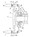
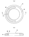
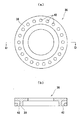
図2は本実施形態に係るロータリ弁を備えた容器検査部の断面図である。図3(a)は図2のB部拡大断面図であり、図3(b)は本実施形態に係るロータリ弁の組み立て直後を示す拡大断面図である。図4(a)は本実施形態に係るロータリ弁の固定側部材の摺接面側を示す平面図であり、図4(b)は図4(a)のC−C線断面図である。図5(a)は本実施形態に係るロータリ弁の回転側部材の摺接面側を示す平面図であり、図5(b)は図5(a)のD−D線断面図である。
【0016】
図2に示すように、容器検査部4は、検査対象となる容器1を保持しつつ回転するメインロータ21を備えている。メインロータ21は主軸23に固着されており、この主軸23は軸受22によって回転自在に支持されている。主軸23の一端には図示しないモータが接続されており、このモータに回転駆動されて主軸23を介してメインロータ21が高速で回転するようになっている。
【0017】
メインロータ21の外周には、容器1を載置するための複数の支持台24が配設されており、各支持台24には容器1を吸着して保持するための吸着パット25が設けられている。各支持台24の下部にはプーリ26が設けられており、プーリ26のV字型溝に当接しながら走行するスピンベルト(図示せず)が、メインロータ21の外周近傍に設置されている。支持台24とプーリ26とは軸27により接続されていて一体的に回転するように構成されており、プーリ26のV字型溝にスピンベルトが当接することによって支持台24及び支持台24に保持された容器1が回転するようになっている。軸27はメインロータ21に固定されるとともに、軸受を内蔵した軸受装置28により回転可能に支持されている。
【0018】
容器1を吸着するための真空源として、本実施形態では真空ポンプ(図示せず)が使用されている。この真空ポンプは固定して設置されているため、固定側(真空ポンプ側)から回転側(メインロータ側)に負圧を供給するために本実施形態に係るロータリ弁31が用いられている。ロータリ弁31は、図3乃至図5に示すように、固定基台32に固定された円板状の固定側部材33と、円筒体35に固定された円板状の回転側部材36とを備えている。円筒体35と主軸23とは、主軸23に設けられたキー38を介して連結され、円筒体35及び回転側部材36と主軸23とが一体的に回転するように構成されている。
【0019】
固定側部材33と回転側部材36とは、互いに摺接しながら回転する摺接面39を有している。図4及び図5に示すように、固定側部材33の摺接面39には円弧状溝40が形成され、回転側部材36の摺接面39には、円弧状溝40に対向する位置で開口する複数の第2連通孔42が同一円周上に形成されている。固定側部材33には円弧状溝40に連通する第1連通孔41が形成されており、第1連通孔41は配管43a(図2参照)を介して図示しない真空ポンプに接続されている。一方、各第2連通孔42は配管43bを介して各吸着パット25に接続されている(図2参照)。
【0020】
本実施形態では、固定側部材33及び回転側部材36はカーボンセラミックスにより形成されている。このカーボンセラミックスは、原料のベースとなる半成コークスに、極めて微細化したSiC、B4Cなどのセラミックスを複合化して生成されたのもであり、次のようなさまざまな優れた性質を備えている。
【0021】
例えば、カーボンセラミックスでは、黒鉛マトリックス中に微細なSiCやB4C等のセラミックスが粒成長して均一に分散しており、これらのセラミックスが大気中の酸素と反応してカーボンセラミックスの表面上に約70μm程度のガラス層(SiO2・B2O3)を形成している。そして、このガラス層により、カーボンセラミックスの表面上では良好な潤滑性を得ることができる。なお、ガラス層が形成される反応式は次の式で表される。
SiC+B4C+O2 → SiO2・B2O3+CO2
また、カーボンセラミックスは、機械加工性に優れているため、低コストで所望の形状に容易に加工することができる。その他にも、高強度、耐熱衝撃性、低吸水性などの優れた性質を有している。
【0022】
図3(a)に示すように、本実施形態に係るロータリ弁31は、回転側部材36を支持するためのスラストベアリング51を備えている。スラストベアリング51は、固定側部材33が固定される固定基台32に設置され、回転側部材36が固着される円筒体35を支持している。即ち、回転側部材36は、上述した摺接面39で支持されるとともに、円筒体35を介してスラストベアリング51によっても支持されている。
【0023】
上述のように構成されたロータリ弁31によれば、回転側部材36が固定側部材33に摺接しながら回転すると、回転側部材36に形成された第2連通孔42が、固定側部材33に形成された円弧状溝40に対向した位置にある間は、第1連通孔41と第2連通孔42とが連通することになる。したがって、第1連通孔41に接続された真空ポンプからの負圧が、第2連通孔42に接続された吸着パット25に供給され、容器1が吸着パット25により吸着保持される。また、第2連通孔42が円弧状溝40からずれると、第1連通孔41と第2連通孔42との連通が遮断され、真空ポンプからの負圧が遮断されて吸着パット25による容器1の吸着保持が解除される。
【0024】
ここで、ロータリ弁においては、固定側部材33と回転側部材36とを常に摺接させて気密性を確保する必要がある。このため、回転側部材36がスラストベアリング51により支持された場合でも、固定側部材33と回転側部材36との間に隙間が生じないようにしなければならない。そこで、本実施形態では、図3(b)に示すように、組み立て直後の構成として、スラストベアリング51と円筒体35との間に30μm程度の隙間dを設けて、摺接面39のみで回転側部材36を支持させる。この状態で回転側部材36が回転すると、固定側部材33と回転側部材36とが摺動して摺接面39が徐々に摩耗していく。この摩耗により、まず、カーボンセラミックスにより形成された回転側部材36及び固定側部材33の摺接面39の面精度を出すことができる。
【0025】
摺接面39の摩耗がさらに進むと、やがて円筒体35がスラストベアリング51に接触し、徐々にスラストベアリング51にかかる荷重が増大する。そして、最終的には、回転側部材36及び円筒体35はほとんどスラストベアリング51によって支持され、摺接面39では、単になじんで当接している程度になるので、それ以上は摺接面39の摩耗は進行することがない。
【0026】
このように、本実施形態では、回転側部材36及び固定側部材33の一定以上の摩耗を防止することができるため、回転側部材36及び固定側部材33の交換が不要になり、半永久的にロータリ弁31を使用することが可能となる。なお、使用するスラストベアリングとしては、特にニードルローラベアリングが好適である。
【0027】
次に、上述のように構成された容器検査部の動作について説明する。
メインロータ21が回転して搬入スターホイール3から容器1が受け渡される位置に近づくと、メインロータ21と一体的に回転する回転側部材36の第2連通孔42が固定側部材33の円弧状溝40に近づく。そして、容器1の受け渡し位置の直前に、第2連通孔42と円弧状溝40とが対向し、これにより、第2連通孔42と第1連通孔41とが連通する。即ち、真空ポンプからの負圧が吸着パット25に供給され、吸着パット25が吸着可能な状態になる。この状態で、容器1が搬入スターホイール3からメインロータ21に受け渡され、同時に、容器1の底面が吸着パット25により吸着保持される。
【0028】
吸着パット25によって保持された容器1はメインロータ21により搬送され、搬送中に撮像装置9により容器1の検査が行われる。検査を終了した容器1が搬出スターホイールへ5の受け渡し位置にさしかかると、第2連通孔42は円弧状溝40からずれ、吸着パット25の吸着状態が解除される。そして、メインロータ21を離れた容器1は搬出スターホイール5へ受け渡される。
【0029】
このように、円弧状溝40は、搬入スターホイール3からの容器受け取り位置から、搬出スターホイール5への容器受け渡し位置にかけて形成されている。そして、この間だけ、吸着パット25が吸着可能な状態となり、容器1がメインロータ21に保持されることになる。
【0030】
なお、上述した本実施形態では、ロータリ弁の設置姿勢を水平とし、真空ポンプを用いて負圧を供給する場合について説明したが、本発明はこれに限られず、ロータリ弁の設置姿勢を垂直にした場合や、正圧を供給する場合にも本発明を適用することができる。また、本実施形態では本発明に係るロータリ弁を容器検査装置に使用した場合について説明したが、本発明はこれに限られず、他の目的を有する容器搬送装置等にも使用することができる。
【0031】
【発明の効果】
以上説明したように、本発明によれば、回転側部材はベアリングにより支持されているので、回転側部材と固定側部材との摺接面の一定以上の摩耗を防止することが可能となり、その結果、半永久的にロータリ弁を使用することが可能となる。また、固定側部材又は回転側部材の少なくとも一方をカーボンセラミックスにより形成したことにより容易に加工することが可能となるほか、良好な潤滑性などのさまざまな優れた効果を得ることが可能となる。
【図面の簡単な説明】
【図1】本発明の一実施形態に係るロータリ弁を備えた容器検査装置の平面図である。
【図2】本発明の一実施形態に係るロータリ弁を備えた容器検査部の断面図である。
【図3】図3(a)は図2のB部拡大図であり、図3(b)は本発明の一実施形態に係るロータリ弁の組み立て直後を示す拡大断面図である。
【図4】図4(a)は本実施形態に係るロータリ弁の固定側部材の摺接面側を示す平面図であり、図4(b)は図4(a)のC−C線断面図である。
【図5】図5(a)は本実施形態に係るロータリ弁の回転側部材の摺接面側を示す平面図であり、図5(b)は図5(a)のD−D線断面図である。
【符号の説明】
1 容器
2 搬入コンベア
3 搬入スターホイール
4 容器検査部
5 搬出スターホイール
6 搬出コンベア
7 インフィールドスクリュー
8 ガイドレール
9 撮像装置
21 メインロータ
22 軸受
23 主軸
24 支持台
25 吸着パット
26 プーリ
27 軸
28 軸受装置
31 ロータリ弁
32 固定基台
33 固定側部材
35 円筒体
36 回転側部材
38 キー
39 摺接面
40 円弧状溝
41 第1連通孔
42 第2連通孔
43 配管
51 スラストベアリング[0001]
BACKGROUND OF THE INVENTION
The present invention relates to a method for manufacturing a rotary valve, and more particularly to a method for manufacturing a rotary valve that can be suitably used for a container transfer device that transfers a container adsorbed by a vacuum suction unit at a high speed.
[0002]
[Prior art]
Generally, a rotary valve includes a stationary member and a rotating member that rotate relative to each other while being in sliding contact with each other. For example, negative pressure from a vacuum source connected to the stationary member is supplied to the rotating member. It is used when doing so. A configuration example of this rotary valve will be described. A first communication hole is formed in the fixed member, and one end of the first communication hole is connected to an arc-shaped groove formed on the sliding contact surface of the fixed member. . A second communication hole is formed in the rotation side member, and one end of the second communication hole is opposed to the above-described arc-shaped groove and opens at the sliding surface of the rotation side member.
[0003]
Under such a configuration, when the rotation side member and the fixed side member rotate relative to each other while sliding, the second communication hole and the first communication hole are provided only while the opening of the second communication hole faces the arcuate groove. And the rotary valve is opened, and fluid can be exchanged between a vacuum source or a compressed air source connected to the stationary member and an operating portion such as an adsorption portion connected to the rotating member. . On the other hand, when the second communication hole deviates from the arc-shaped groove, the communication between the second communication hole and the first communication hole is blocked, the rotary valve is closed, and the fluid between the rotating side member and the fixed side member is closed. Transfers are blocked.
[0004]
The rotary valve configured as described above is widely used in a container transport device that transports a container at a high speed and inspects the container. A general container transport device includes a star wheel having an adsorption part, and is configured to convey the container by rotating the star wheel at high speed while adsorbing the container to the adsorption part by negative pressure from a vacuum pump. . Usually, since the vacuum pump is fixedly installed, the rotary valve described above is used to supply the negative pressure from the vacuum pump to the rotating star wheel side from the fixed side where the vacuum pump is arranged. .
[0005]
In such a rotary valve, since the stationary member and the rotating member are in sliding contact with each other while being attracted to each other by negative pressure, wear of the sliding contact surface easily proceeds. For this reason, conventionally, as a material for forming the stationary member and the rotating member,
(1) Combination of alumina ceramics
(2) A combination of a steel sheet coated with a fluororesin coated super steel sheet,
Etc. are used.
[0006]
[Problems to be solved by the invention]
However, in the case of a combination of the above-mentioned alumina ceramics, although the wear resistance is excellent, there is a problem that the machinability is poor and the member is easily chipped during processing. And in order to prevent such a member from being chipped, a high processing technique is required, which is inevitably very expensive. Also, as wear on the sliding surface progresses, edges such as arc-shaped grooves and communication holes are chipped, and the chipped pieces clog the piping and reduce the degree of vacuum, and further, the pieces enter the vacuum pump. There is a problem that the vacuum pump is damaged.
[0007]
In addition, in the case of a combination of the above-described ultra-steel sheet coated with a fluororesin and a steel sheet, there is a problem that it is difficult to obtain the accuracy of the bonding surface between the ultra-steel sheet and the steel sheet in the manufacturing process, and it is difficult to ensure stable quality. is there. And from the difficulty of the process, it becomes very expensive for the same reason as the case of the combination of alumina ceramics. In addition, the fluororesin coating is susceptible to surface accuracy errors on the super steel plate side, and there is a problem that uneven wear or the like is likely to occur.
[0008]
Furthermore, even when a valve is formed using the above-described materials, it is worn out by about 200 to 300 μm in a service period of 4000 hours (about 2 years). For this reason, it is necessary to periodically replace the worn valve, and there is a problem that productivity is lowered because the operation must be stopped during the replacement work.
[0009]
The present invention has been made in view of the above-described problems, and is a method of manufacturing a rotary valve that can be easily processed and can be used semipermanently while preventing wear of members constituting the valve beyond a certain level. The purpose is to provide.
[0010]
[Means for Solving the Problems]
In order to achieve the above object, one aspect of the present invention includes a stationary member and a rotating member disposed above the stationary member, and the stationary member and the rotating member are mutually connected. By relatively rotating while sliding, the first communication hole formed in the stationary member and the second communication hole formed in the rotating member intermittently communicate with each other, and the first communication of the stationary member is performed. In the method of manufacturing a rotary valve configured to supply a negative pressure from a vacuum source connected to a hole to the second communication hole of the rotary side member, a thrust is provided between the fixed side member and the rotary side member. Immediately after assembling the bearing, a clearance is provided on the upper surface of the thrust bearing, and the rotating side member is supported on the fixed side member only by a sliding surface where the fixed side member and the rotating side member are in sliding contact with each other. The rotation in the state Rotating the member, after abrading the sliding surface by the rotation, characterized in that so as to support the rotating member by the thrust bearing disposed on the inner side of the stationary member.
In a preferred aspect of the present invention, at least one of the fixed side member and the rotation side member is formed of carbon ceramics .
[0011]
According to the present invention configured as described above, since the rotation side member is supported by the bearing, the sliding contact surface between the fixed side member and the rotation side member hardly receives a load. Therefore, it is possible to prevent the sliding surface from being worn beyond a certain level, and as a result, it is possible to use the rotary valve semipermanently.
[0012]
Further, wear can be further prevented by using carbon ceramics having good lubricity and high strength for the material of either or both of the fixed side member and the rotary side member. Furthermore, since carbon ceramics are excellent in machinability, advanced machining techniques are not required, and as a result, production costs can be reduced. In addition, the characteristics of carbon ceramics include advantages such as thermal shock resistance and low water absorption, and the function of the rotary valve can be maintained well against sudden external factors.
[0013]
DETAILED DESCRIPTION OF THE INVENTION
Hereinafter, an embodiment of a rotary valve according to the present invention will be described with reference to the drawings.
FIG. 1 is a plan view of a container inspection apparatus provided with a rotary valve according to this embodiment.
As shown in FIG. 1, a container inspection apparatus including a rotary valve according to this embodiment includes a carry-in
[0014]
The carry-in
[0015]
Next, the container inspection part provided with the rotary valve according to the present embodiment will be described.
FIG. 2 is a cross-sectional view of a container inspection unit including a rotary valve according to the present embodiment. FIG. 3A is an enlarged cross-sectional view of a portion B in FIG. 2, and FIG. 3B is an enlarged cross-sectional view immediately after the assembly of the rotary valve according to the present embodiment. Fig.4 (a) is a top view which shows the sliding contact surface side of the stationary side member of the rotary valve which concerns on this embodiment, FIG.4 (b) is CC sectional view taken on the line of Fig.4 (a). Fig.5 (a) is a top view which shows the sliding surface side of the rotation side member of the rotary valve which concerns on this embodiment, FIG.5 (b) is the DD sectional view taken on the line of Fig.5 (a).
[0016]
As shown in FIG. 2, the container inspection unit 4 includes a
[0017]
A plurality of
[0018]
In this embodiment, a vacuum pump (not shown) is used as a vacuum source for adsorbing the
[0019]
The fixed
[0020]
In the present embodiment, the fixed
[0021]
For example, in carbon ceramics, ceramics such as fine SiC and B 4 C are grown and uniformly dispersed in a graphite matrix, and these ceramics react with oxygen in the atmosphere to form on the surface of the carbon ceramics. A glass layer (SiO 2 · B 2 O 3 ) of about 70 μm is formed. And with this glass layer, good lubricity can be obtained on the surface of the carbon ceramics. The reaction formula for forming the glass layer is represented by the following formula.
SiC + B 4 C + O 2 → SiO 2 .B 2 O 3 + CO 2
Moreover, since carbon ceramics is excellent in machinability, it can be easily processed into a desired shape at low cost. In addition, it has excellent properties such as high strength, thermal shock resistance, and low water absorption.
[0022]
As shown in FIG. 3A, the
[0023]
According to the
[0024]
Here, in the rotary valve, it is necessary to keep the
[0025]
As the wear of the sliding
[0026]
As described above, in the present embodiment, the rotation-
[0027]
Next, the operation of the container inspection unit configured as described above will be described.
When the
[0028]
The
[0029]
Thus, the arc-shaped
[0030]
In the above-described embodiment, the case where the rotary valve is installed horizontally and the negative pressure is supplied using the vacuum pump has been described. However, the present invention is not limited to this, and the rotary valve is installed vertically. The present invention can also be applied to the case where a positive pressure is supplied. Moreover, although this embodiment demonstrated the case where the rotary valve which concerns on this invention was used for a container inspection apparatus, this invention is not restricted to this, It can be used also for the container conveyance apparatus etc. which have another objective.
[0031]
【Effect of the invention】
As described above, according to the present invention, since the rotation side member is supported by the bearing, it is possible to prevent the sliding contact surface between the rotation side member and the fixed side member from being worn more than a certain amount. As a result, the rotary valve can be used semipermanently. In addition, it is possible to easily process at least one of the fixed side member and the rotation side member by using carbon ceramics, and it is possible to obtain various excellent effects such as good lubricity.
[Brief description of the drawings]
FIG. 1 is a plan view of a container inspection apparatus provided with a rotary valve according to an embodiment of the present invention.
FIG. 2 is a cross-sectional view of a container inspection unit including a rotary valve according to an embodiment of the present invention.
3 (a) is an enlarged view of a portion B in FIG. 2, and FIG. 3 (b) is an enlarged cross-sectional view immediately after assembly of the rotary valve according to the embodiment of the present invention.
4 (a) is a plan view showing a sliding contact surface side of the fixed side member of the rotary valve according to the present embodiment, and FIG. 4 (b) is a cross-sectional view taken along line CC in FIG. 4 (a). FIG.
FIG. 5 (a) is a plan view showing the sliding surface side of the rotary side member of the rotary valve according to the present embodiment, and FIG. 5 (b) is a cross-sectional view taken along line DD of FIG. 5 (a). FIG.
[Explanation of symbols]
DESCRIPTION OF
Claims (2)
前記固定側部材と前記回転側部材との間にスラストベアリングを配置した組み立て直後においては前記スラストベアリングの上面には隙間を設け、前記固定側部材と前記回転側部材とが互いに摺接する摺接面のみで前記回転側部材を前記固定側部材に支持させた状態で前記回転側部材を回転させ、この回転により前記摺接面を摩耗させた後に、前記固定側部材の内側に配置された前記スラストベアリングによって前記回転側部材を支持させるようにしたことを特徴とするロータリ弁の製造方法。A fixed side member and a rotation side member disposed above the fixed side member. The fixed side member and the rotation side member rotate relative to each other while being in sliding contact with each other, thereby forming the fixed side member. The first communication hole intermittently communicates with the second communication hole formed in the rotation side member, and negative pressure from a vacuum source connected to the first communication hole of the fixed side member is applied to the rotation side member. In the manufacturing method of the rotary valve configured to be supplied to the second communication hole,
Immediately after assembling the thrust bearing between the fixed side member and the rotating side member, a clearance is provided on the upper surface of the thrust bearing so that the fixed side member and the rotating side member are in sliding contact with each other. said rotary member is rotated the rotatable member in the state of being supported on the stationary member only, after abrading the sliding surface by the rotation, the thrust that is disposed on the inner side of the fixed-side member A method of manufacturing a rotary valve , wherein the rotary side member is supported by a bearing.
Priority Applications (1)
| Application Number | Priority Date | Filing Date | Title |
|---|---|---|---|
| JP2001296090A JP5017635B2 (en) | 2001-09-27 | 2001-09-27 | Manufacturing method of rotary valve |
Applications Claiming Priority (1)
| Application Number | Priority Date | Filing Date | Title |
|---|---|---|---|
| JP2001296090A JP5017635B2 (en) | 2001-09-27 | 2001-09-27 | Manufacturing method of rotary valve |
Publications (2)
| Publication Number | Publication Date |
|---|---|
| JP2003097746A JP2003097746A (en) | 2003-04-03 |
| JP5017635B2 true JP5017635B2 (en) | 2012-09-05 |
Family
ID=19117397
Family Applications (1)
| Application Number | Title | Priority Date | Filing Date |
|---|---|---|---|
| JP2001296090A Expired - Lifetime JP5017635B2 (en) | 2001-09-27 | 2001-09-27 | Manufacturing method of rotary valve |
Country Status (1)
| Country | Link |
|---|---|
| JP (1) | JP5017635B2 (en) |
Families Citing this family (1)
| Publication number | Priority date | Publication date | Assignee | Title |
|---|---|---|---|---|
| JP5103334B2 (en) * | 2008-09-11 | 2012-12-19 | 中部電力株式会社 | Sliding switching valve |
Family Cites Families (3)
| Publication number | Priority date | Publication date | Assignee | Title |
|---|---|---|---|---|
| JP2000226264A (en) * | 1999-02-02 | 2000-08-15 | Mitsubishi Chemicals Corp | Production of carbon-ceramic composite molded form |
| JP2005132618A (en) * | 2003-10-31 | 2005-05-26 | Kirin Techno-System Corp | Star wheel device |
| JP2008051146A (en) * | 2006-08-22 | 2008-03-06 | Kirin Techno-System Co Ltd | Rotary valve |
-
2001
- 2001-09-27 JP JP2001296090A patent/JP5017635B2/en not_active Expired - Lifetime
Also Published As
| Publication number | Publication date |
|---|---|
| JP2003097746A (en) | 2003-04-03 |
Similar Documents
| Publication | Publication Date | Title |
|---|---|---|
| CN104551902B (en) | Substrate board treatment and substrate processing method using same | |
| KR101522972B1 (en) | Polishing apparatus, polishing method, pressure member for pressing polishing tool | |
| CN103447939B (en) | Lapping device and Ginding process | |
| CN102699794B (en) | Lapping device and Ginding process | |
| US6390753B1 (en) | System for loading, processing and unloading substrates arranged on a carrier | |
| CN103962939B (en) | Lapping device and Ginding process | |
| JPS60155358A (en) | Method and device for grinding surface of semiconductor wafer | |
| JP2008120465A (en) | Container transfer device | |
| KR100781912B1 (en) | Gaseous phase growing device | |
| TW201420525A (en) | Roller conveyor, plate body inspecting device, and glass plate manufacturing device | |
| JP4818995B2 (en) | Double-head surface grinding machine | |
| JP5017635B2 (en) | Manufacturing method of rotary valve | |
| EP0158800B1 (en) | Vacuum-to-vacuum entry system apparatus | |
| JP2007250601A (en) | Suction pad for substrate conveyor and method for conveying substrate | |
| JP2008051146A (en) | Rotary valve | |
| JP2011167810A (en) | Wire saw | |
| TW201233503A (en) | Grinder | |
| KR101880488B1 (en) | Apparatus for polishing the end surface of valve spindle | |
| JP2009166214A (en) | Grinder | |
| WO2001023110A1 (en) | Transfer device, inspection device, and aligningly feeding device | |
| JP2004026348A (en) | Suction roller | |
| KR20220167529A (en) | Lapping device for quartz ring wrapping with high movement convenience and high processing precision | |
| US5895312A (en) | Apparatus for removing surface irregularities from a flat workpiece | |
| JP2005132618A (en) | Star wheel device | |
| CN115505905B (en) | Mechanical handle, mechanical arm assembly and coating equipment |
Legal Events
| Date | Code | Title | Description |
|---|---|---|---|
| A621 | Written request for application examination |
Free format text: JAPANESE INTERMEDIATE CODE: A621 Effective date: 20080911 |
|
| A977 | Report on retrieval |
Free format text: JAPANESE INTERMEDIATE CODE: A971007 Effective date: 20101216 |
|
| A131 | Notification of reasons for refusal |
Free format text: JAPANESE INTERMEDIATE CODE: A131 Effective date: 20110419 |
|
| A521 | Written amendment |
Free format text: JAPANESE INTERMEDIATE CODE: A523 Effective date: 20110608 |
|
| A131 | Notification of reasons for refusal |
Free format text: JAPANESE INTERMEDIATE CODE: A131 Effective date: 20111206 |
|
| A521 | Written amendment |
Free format text: JAPANESE INTERMEDIATE CODE: A523 Effective date: 20120117 |
|
| TRDD | Decision of grant or rejection written | ||
| A01 | Written decision to grant a patent or to grant a registration (utility model) |
Free format text: JAPANESE INTERMEDIATE CODE: A01 Effective date: 20120515 |
|
| A01 | Written decision to grant a patent or to grant a registration (utility model) |
Free format text: JAPANESE INTERMEDIATE CODE: A01 |
|
| A61 | First payment of annual fees (during grant procedure) |
Free format text: JAPANESE INTERMEDIATE CODE: A61 Effective date: 20120517 |
|
| R150 | Certificate of patent or registration of utility model |
Ref document number: 5017635 Country of ref document: JP Free format text: JAPANESE INTERMEDIATE CODE: R150 Free format text: JAPANESE INTERMEDIATE CODE: R150 |
|
| FPAY | Renewal fee payment (event date is renewal date of database) |
Free format text: PAYMENT UNTIL: 20150622 Year of fee payment: 3 |
|
| R250 | Receipt of annual fees |
Free format text: JAPANESE INTERMEDIATE CODE: R250 |
|
| R250 | Receipt of annual fees |
Free format text: JAPANESE INTERMEDIATE CODE: R250 |
|
| R250 | Receipt of annual fees |
Free format text: JAPANESE INTERMEDIATE CODE: R250 |
|
| R250 | Receipt of annual fees |
Free format text: JAPANESE INTERMEDIATE CODE: R250 |
|
| R250 | Receipt of annual fees |
Free format text: JAPANESE INTERMEDIATE CODE: R250 |