JP5009331B2 - Drum type granulator and granulation method - Google Patents
Drum type granulator and granulation method Download PDFInfo
- Publication number
- JP5009331B2 JP5009331B2 JP2009086611A JP2009086611A JP5009331B2 JP 5009331 B2 JP5009331 B2 JP 5009331B2 JP 2009086611 A JP2009086611 A JP 2009086611A JP 2009086611 A JP2009086611 A JP 2009086611A JP 5009331 B2 JP5009331 B2 JP 5009331B2
- Authority
- JP
- Japan
- Prior art keywords
- drum
- rubber
- fixing member
- rotating drum
- rubber liner
- Prior art date
- Legal status (The legal status is an assumption and is not a legal conclusion. Google has not performed a legal analysis and makes no representation as to the accuracy of the status listed.)
- Active
Links
Images


Landscapes
- Glanulating (AREA)
- Manufacture And Refinement Of Metals (AREA)
Description
本発明は、ドラム型造粒機及び造粒方法に関し、特に、ドラム内周面に対する被造粒物の付着を防止するためのドラム型造粒機及び造粒方法に関する。 The present invention relates to a drum-type granulator and a granulation method, and more particularly, to a drum-type granulator and a granulation method for preventing adhesion of a granulated material to an inner peripheral surface of a drum.
従来、粉体や粒体からなる各種原料を造粒するため造粒機として、ドラム型造粒機が広く用いられている。例えば、焼結原料の事前処理工程においても、鉄鉱石の粉粒体を含む焼結原料をドラム型造粒機により造粒し、得られた粒径数mm程度の造粒物を焼結機に投入することが一般的である。 Conventionally, a drum type granulator is widely used as a granulator for granulating various raw materials composed of powder and granules. For example, even in the pretreatment step of the sintered raw material, the sintered raw material containing iron ore particles is granulated by a drum type granulator, and the obtained granulated material having a particle size of about several mm is sintered. It is common to put in
ドラム型造粒機では、傾斜配置された円筒形の回転ドラムを回転させながら、この回転ドラム内にバインダー又は水の少なくともいずれかが添加された原料(被造粒物)を投入し、当該原料が回転ドラムの入側から出側まで移動する間に、回転ドラム内で原料を転動させて造粒する構成である(例えば特許文献1参照。)。かかるドラム型造粒機では、焼結原料などの付着性の高い原料を造粒する場合には、ドラム内周面に原料が付着してしまうため、適正な転動造粒を行うことができず、造粒物を安定製造できなくなるという問題があった。 In a drum granulator, while rotating a cylindrical rotating drum arranged in an inclined manner, a raw material (granulated material) to which at least one of a binder and water is added is put into the rotating drum, and the raw material Is a structure in which the raw material rolls and granulates in the rotating drum while it moves from the inlet side to the outlet side of the rotating drum (see, for example, Patent Document 1). In such a drum type granulator, when a highly adherent raw material such as a sintered raw material is granulated, the raw material adheres to the inner peripheral surface of the drum, so that proper rolling granulation can be performed. However, there was a problem that the granulated product could not be stably produced.
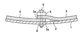
かかる問題に対処すべく、従来のドラム型造粒機においては、図1に示すように、回転ドラム1の内周面2に対する原料の付着を防止するために、回転ドラム1の内周面2にゴムライナー3(弾性体であるゴムシートからなるライニング材)を装着していた。さらに、回転ドラム1の内周面2とゴムライナー3との間に空間を持たせることにより、回転ドラム1の回転に伴ってゴムライナー3が上方に移動したときに、弾力性を有するゴムライナー3が重力により下方に撓むように変形することを利用して、ゴムライナー3に対する原料の付着をも防止していた。
In order to cope with such a problem, in the conventional drum type granulator, as shown in FIG. 1, in order to prevent the raw material from adhering to the inner
例えば、特許文献2には、回転ドラムの内周面にゴムシートを横断面が波状となるように固設し、かつ、このゴムシートとドラム内周面との間に形成される長手方向の各空間部に、ゴム状弾性体よりなる支持体を設けた回転造粒装置が開示されている。また、特許文献3には、造粒機のドラム内周面にゴム製のライニング材を設け、該ライニング材とドラム内周面との間に閉じられた空間部を形成することが開示されている。
For example, in
ところで、上記従来のドラム型造粒機においては、入手可能なゴムライナーの大きさの制約や装着の容易さを考慮して、図1に示したように、複数枚の矩形状のゴムライナー3を周方向に継ぎ合わせて回転ドラム1の内周面2に装着することが一般的であった。この場合、複数本の板状の固定部材4(押さえ板)を、回転ドラム1の長手方向に対して平行に所定間隔で配置し、この固定部材4を用いて、複数枚のゴムライナー3の周方向端部にある継ぎ代を回転ドラム1の内周面2に固定していた。詳細には、図2に示すように、固定部材4と回転ドラム1の内周面2との間に、相隣接する2枚のゴムライナー3の継ぎ代3aを挟み込むように配置し、ボルト5及びナット6により当該固定部材4を回転ドラム1に固着していた。なお、固定部材4は、回転ドラム1を回転させたときに、回転ドラム1の底部に滞留している原料(図示せず。)を上方に掻き上げるためのリフターとしても機能し、原料の掻き上げ量を制御するために、固定部材4の高さ(板厚)や幅が適正な寸法に設定されている。
By the way, in the above conventional drum type granulator, in consideration of the restriction of the size of the available rubber liner and the ease of mounting, a plurality of
しかしながら、上記ゴムライナー3を固定するための固定部材4は、回転ドラム1内側に向けて突出した状態で露出していた。このため、ドラム型造粒機において付着性の高い原料を造粒した場合、図3に示すように、固定部材4に原料が徐々に固着していき、固定部材4周辺に大きな固着物7が形成されてしまうという問題があった。例えば、焼結原料の事前処理行程で使用されるドラム造粒機において、付着性が非常に強い焼結原料を使用する場合、固定部材4に対する焼結原料の付着が激しく、安定した転動造粒を行うためには、ゴムライナー3による付着防止だけでは不十分であった。
However, the
詳細には、一般的に固定部材4としては鉄板やゴム板が使用されるが、当該固定部材4はボルト5等により締結・固定されるため、弾力性が小さく、回転ドラム1が回転してもほとんど変形しない。このため、付着性の高い原料を用いた場合、固定部材4に対する原料の固着が激しくなり、固定部材4の周囲に大きな固着物7が形成され、当該固着物7は回転ドラム1が回転しても落下しない。すると、このように固定部材4の周囲に形成された固着物7によって、原料の掻き上げ量及び掻き上げ高さが増大するので、原料を適正に転動造粒できなくなってしまう。即ち、適正な転動造粒を行うためには、回転ドラム1内でリフターにより適切な量の原料を適切な高さまで掻き上げることで、原料を円滑に転動運動させることが求められる。しかし、上記固着物7によって、回転ドラム1内の原料が、必要以上に高い位置まで大量に掻き上げられると、当該原料が高い位置からドラム底部まで一気に落下して、既成の造粒物が破壊されてしまうこととなり、適正な転動造粒が阻害される。また、非常に大きく成長した固着物7が剥がれ落ちた場合には、その大きな塊が造粒機から排出されることなり、焼結機にそのまま投入できない等といった弊害が発生することもある。
In detail, an iron plate or a rubber plate is generally used as the
以上説明した事情から、従来では、ドラム型造粒機において、回転ドラムの内周面に対する原料の付着のみならず、ゴムライナーを固定する固定部材に対する原料の付着をも好適に防止して、回転ドラム内で原料を適正に転動造粒できる方法が希求されていた。 From the circumstances described above, conventionally, in a drum type granulator, not only the adhesion of the raw material to the inner peripheral surface of the rotating drum but also the prevention of the adhesion of the raw material to the fixing member for fixing the rubber liner is preferably prevented. There has been a demand for a method capable of appropriately rolling and granulating raw materials in a drum.
そこで、本発明は、上記問題に鑑みてなされたものであり、本発明の目的とするところは、ゴムライナーを固定する固定部材に対する原料の付着を防止して、適正な転動造粒を安定的に実現することが可能な、新規かつ改良されたドラム型造粒機及び造粒方法を提供することにある。 Therefore, the present invention has been made in view of the above problems, and an object of the present invention is to prevent the adhesion of raw materials to a fixing member for fixing a rubber liner and to stabilize proper rolling granulation. It is an object of the present invention to provide a new and improved drum granulator and granulation method that can be realized in a practical manner.
上記課題を解決するために、本発明のある観点によれば、円筒状の回転ドラムと、矩形状のゴムシートからなり、前記回転ドラムの内周面全体を覆うように前記回転ドラムの周方向に継ぎ合わせて配置される複数枚のゴムライナーと、前記ゴムライナーを前記回転ドラムの内周面に固定する複数本の固定部材と、を備え、前記固定部材は、前記周方向に相隣接する前記ゴムライナーの継ぎ目に沿って、前記回転ドラムの長手方向に対して平行に配設され、前記周方向に相隣接する前記ゴムライナーの継ぎ代を、前記回転ドラムの内周面との間に挟み込むようにして前記回転ドラムの内周面に固定し、前記周方向に相隣接する前記ゴムライナーの継ぎ目において、少なくとも一方のゴムライナーの継ぎ代は、前記固定部材を巻き込むように覆うことを特徴とする、ドラム型造粒機が提供される。 In order to solve the above-described problem, according to an aspect of the present invention, the circumferential direction of the rotating drum is formed of a cylindrical rotating drum and a rectangular rubber sheet, and covers the entire inner peripheral surface of the rotating drum. And a plurality of fixing members that fix the rubber liner to the inner peripheral surface of the rotating drum, and the fixing members are adjacent to each other in the circumferential direction. A joint margin of the rubber liner, which is arranged in parallel to the longitudinal direction of the rotating drum along the seam of the rubber liner and is adjacent to the circumferential direction, is formed between the inner peripheral surface of the rotating drum. The rubber drum is fixed to the inner peripheral surface of the rotating drum so as to be sandwiched, and at the joint of the rubber liners adjacent to each other in the circumferential direction, the joint margin of at least one rubber liner covers the fixing member so as to be caught. Characterized the door, a drum granulator is provided.
かかる構成により、ゴムライナーの継ぎ目において、少なくとも一方のゴムライナーの継ぎ代が固定部材を巻き込むように覆っているので、回転ドラム内で固定部材に被造粒物が付着することを防止できる。また、各ゴムライナーの周方向両端部を固定部材と回転ドラムの内周面との間に挟持するようにして、各ゴムライナーが回転ドラムの内周面に取り付けられる。このため、各ゴムライナーは、回転ドラムの回転に伴ってドラム内の上方に移動したときには、回転ドラムの内側に向けて断面凸状に変形するので、当該各ゴムライナーに付着した被造粒物を離脱させることができる。 With such a configuration, since the joint of at least one rubber liner covers the joint of the rubber liner so as to entrain the fixing member, it is possible to prevent the granulated material from adhering to the fixing member in the rotating drum. Further, each rubber liner is attached to the inner peripheral surface of the rotating drum such that both ends in the circumferential direction of each rubber liner are sandwiched between the fixing member and the inner peripheral surface of the rotating drum. For this reason, when each rubber liner moves upward in the drum as the rotary drum rotates, the rubber liner is deformed into a convex cross section toward the inner side of the rotary drum. Can be removed.
また、前記ゴムライナーの継ぎ代のうち前記固定部材を覆う部分は、前記固定部材に固定されておらず、前記固定部材に対して接離可能であるようにすることもできる。これにより、ゴムライナーの周方向端部の継ぎ代のうち固定部材を覆う部分は、遊びがあるため、回転ドラムの回転に伴って固定部材に対して当接又は離間動作する。このため、当該部分に付着した被造粒物を好適に離脱させることができ、また、当該部分に対して固着物が固着しにくい。 Moreover, the part which covers the said fixing member among the joint margins of the said rubber liner is not being fixed to the said fixing member, but can also be made to contact / separate with respect to the said fixing member. Thereby, the part which covers a fixing member among the joint margins of the circumferential direction edge part of a rubber liner has a play, Therefore It contacts or separates with respect to a fixing member with rotation of a rotating drum. For this reason, the to-be-granulated material adhering to the said part can be made to detach | leave suitably, and a fixed substance cannot adhere to the said part easily.
また、前記周方向に相隣接する前記ゴムライナーの継ぎ目ごとに、1本の前記固定部材が設置され、前記周方向に相隣接する前記ゴムライナーの継ぎ目において、一方のゴムライナーの継ぎ代は、前記回転ドラムの内周面に沿って配設され、他方のゴムライナーの継ぎ代は、前記固定部材を巻き込むように覆い、前記周方向に相隣接する前記ゴムライナーの継ぎ代の先端部は、相互に重なり合うように配置され、前記1本の固定部材と前記回転ドラムの内周面との間に挟み込まれて前記回転ドラムの内周面に固定されるようにしてもよい。これにより、1本の固定部材を用いて、周方向に相隣接するゴムライナーの継ぎ目を回転ドラムに対して好適に固定できるとともに、当該固定部材を他方のゴムライナーの継ぎ代で適切に覆うことができる。 In addition, one fixing member is installed for each joint of the rubber liners adjacent to each other in the circumferential direction, and in the joint of the rubber liners adjacent to each other in the circumferential direction, the joint margin of one rubber liner is: It is arranged along the inner peripheral surface of the rotating drum, and the joint margin of the other rubber liner covers the fixing member so as to be wound, and the tip portion of the joint margin of the rubber liner adjacent to the circumferential direction is They may be arranged so as to overlap each other, and may be sandwiched between the one fixing member and the inner peripheral surface of the rotating drum and fixed to the inner peripheral surface of the rotating drum. Accordingly, the seam of the rubber liners adjacent to each other in the circumferential direction can be suitably fixed to the rotating drum using one fixing member, and the fixing member is appropriately covered with the seam allowance of the other rubber liner. Can do.
さらに、前記一方のゴムライナーは、前記回転ドラムの回転方向側に配置されたゴムライナーであり、前記他方のゴムライナーは、前記回転ドラムの回転方向逆側に配置されたゴムライナーであり、前記他方のゴムライナーの継ぎ代により覆われた前記固定部材により、前記回転ドラム内の被造粒物を掻き上げるようにしてもよい。これにより、回転方向逆側に配置されたゴムライナーの継ぎ代により覆われた固定部材をリフターとして機能させ、回転ドラム内の被造粒物を掻き上げて、転動運動させることができる。また、当該固定部材の回転ドラムの径方向の高さ(リフター高さ)を調節することで、被造粒物の掻き上げ量及び掻き上げ高さを適正値に制御できる。 Further, the one rubber liner is a rubber liner disposed on the rotating direction side of the rotating drum, and the other rubber liner is a rubber liner disposed on the rotating direction opposite side of the rotating drum, The granulated material in the rotating drum may be scraped up by the fixing member covered by the joint margin of the other rubber liner. Thereby, the fixing member covered by the joint margin of the rubber liner disposed on the opposite side in the rotation direction can function as a lifter, and the granulated material in the rotating drum can be scraped and rolled. Further, by adjusting the radial height (lifter height) of the rotating drum of the fixed member, the scraping amount and the scraping height of the granulated material can be controlled to appropriate values.
さらに、前記被造粒物の付着性に応じて、前記回転ドラムの回転方向を変更するようにしてもよい。これにより、被造粒物の付着性が高い場合には、回転ドラムの回転方向を逆にすることで、ゴムライナーの継ぎ代により覆われた固定部材をリフターとして機能させないようにして、掻き上げ量及び掻き上げ高さを調節できる。 Furthermore, you may make it change the rotation direction of the said rotating drum according to the adhesiveness of the said granulated material. As a result, when the adherence of the granulated material is high, the rotation direction of the rotating drum is reversed so that the fixing member covered by the joint margin of the rubber liner does not function as a lifter and is scraped up. The amount and scraping height can be adjusted.
また、前記周方向に相隣接する前記ゴムライナーの継ぎ目ごとに、2本の前記固定部材が並設され、前記周方向に相隣接する前記ゴムライナーの継ぎ目において、一方のゴムライナーの継ぎ代と他方のゴムライナーの継ぎ代とが、前記2本の固定部材の間で相互に接触するように配設され、前記一方のゴムライナーの継ぎ代は、前記2本の固定部材のうちの一方の固定部材を巻き込むように覆い、当該継ぎ代の先端部は、前記一方の固定部材と前記回転ドラムの内周面との間に挟み込まれて前記回転ドラムの内周面に固定され、前記他方のゴムライナーの継ぎ代は、前記2本の固定部材のうちの他方の固定部材を巻き込むように覆い、当該継ぎ代の先端部は、前記他方の固定部材と前記回転ドラムの内周面との間に挟み込まれて前記回転ドラムの内周面に固定されるようにしてもよい。これにより、2本の固定部材を用いて、周方向に相隣接するゴムライナーの継ぎ目を回転ドラムに対して好適に固定できるとともに、当該2本の固定部材をそれぞれのゴムライナーの継ぎ代で適切に覆うことができる。 Further, two fixing members are juxtaposed for each joint of the rubber liners adjacent to each other in the circumferential direction, and at the joint of the rubber liners adjacent to each other in the circumferential direction, The joint of the other rubber liner is disposed so as to come into contact with each other between the two fixing members, and the joint of the one rubber liner is connected to one of the two fixing members. A fixing member is covered so that the tip end portion of the joint is sandwiched between the one fixing member and the inner peripheral surface of the rotating drum and fixed to the inner peripheral surface of the rotating drum. The seam allowance of the rubber liner covers the other fixing member of the two fixing members so that the tip of the seam allowance is between the other fixing member and the inner peripheral surface of the rotating drum. The rotating drum is sandwiched between It may be fixed to an inner circumferential surface of the. Accordingly, the seams of the rubber liners adjacent to each other in the circumferential direction can be suitably fixed to the rotating drum using the two fixing members, and the two fixing members are appropriately used at the joints of the respective rubber liners. Can be covered.
さらに、前記一方の固定部材の前記回転ドラムの径方向の高さと、前記他方の固定部材の前記回転ドラムの径方向の高さは、同一であるようにしてもよい。これにより、一方のゴムライナーの継ぎ代により覆われた一方の固定部材と、他方のゴムライナーの継ぎ代により覆われた他方の固定部材との段差を無くして、周方向に相隣接するゴムライナーの継ぎ目の上面を、ほぼ面一にすることができる。よって、被造粒物の付着性が高い場合などに、当該継ぎ目におけるリフター機能を大幅に弱めて、リフターによる被造粒物の掻き上げ量を大幅に低減することができる。 Furthermore, the radial height of the rotating drum of the one fixing member and the radial height of the rotating drum of the other fixing member may be the same. This eliminates a step between one fixing member covered by the joint of one rubber liner and the other fixing member covered by the joint of the other rubber liner, and adjacent rubber liners in the circumferential direction. The top surface of the seam can be substantially flush. Therefore, when the adherence of the granulated material is high, the lifter function at the joint can be greatly weakened, and the amount of the granulated material scraped up by the lifter can be greatly reduced.
また、前記一方のゴムライナーは、前記回転ドラムの回転方向側に配置されたゴムライナーであり、前記他方のゴムライナーは、前記回転ドラムの回転方向逆側に配置されたゴムライナーであり、前記他方の固定部材の前記回転ドラムの径方向の高さは、前記一方の固定部材の前記回転ドラムの径方向の高さよりも高く、前記他方のゴムライナーの継ぎ代により覆われた前記他方の固定部材と、前記一方のゴムライナーの継ぎ代により覆われた前記一方の固定部材との段差により、前記回転ドラム内の被造粒物を掻き上げるようにしてもよい。これにより、当該段差をリフターとして機能させ、回転ドラム内の被造粒物を掻き上げて、転動運動させることができる。また、2本の固定部材の高さの差(リフター高さ)を調節することで、被造粒物の掻き上げ量及び掻き上げ高さを適正値に制御できる。 Further, the one rubber liner is a rubber liner disposed on the rotating direction side of the rotating drum, and the other rubber liner is a rubber liner disposed on the rotating direction opposite side of the rotating drum, The height of the other fixing member in the radial direction of the rotating drum is higher than the height of the one fixing member in the radial direction of the rotating drum, and the other fixing member is covered by the joint margin of the other rubber liner. The granulated material in the rotating drum may be scraped up by a step between the member and the one fixing member covered by the joint margin of the one rubber liner. Thereby, the said level | step difference can be functioned as a lifter, and the to-be-granulated material in a rotating drum can be raked up and it can be rolled. Further, by adjusting the difference in height (lifter height) between the two fixing members, it is possible to control the scraping amount and scraping height of the granulated material to appropriate values.
また、上記課題を解決するために、本発明のある観点によれば、前記ドラム型造粒機を用いて被造粒物を造粒する造粒方法であって、回転ドラムを回転させて前記被造粒物を造粒する際に、固定部材により前記回転ドラムの内周面に取り付けられた各ゴムライナーが、前記回転ドラムの回転に伴って上方に移動したときに、前記回転ドラムの内側に向けて断面凸状に変形することによって、前記ゴムライナーに付着した前記被造粒物を離脱させることを特徴とする、造粒方法が提供される。 In order to solve the above problems, according to an aspect of the present invention, there is provided a granulation method for granulating a granulated material using the drum type granulator, wherein the rotary drum is rotated to When granulating the material to be granulated, each rubber liner attached to the inner peripheral surface of the rotating drum by a fixing member moves upward along with the rotation of the rotating drum. The granulation method is characterized in that the granulated material adhering to the rubber liner is released by being deformed into a convex cross section toward the surface.
以上説明したように本発明によれば、ゴムライナーを固定する固定部材に対する原料の付着を防止して、適正な転動造粒を安定的に実現することができる。 As described above, according to the present invention, it is possible to prevent the raw material from adhering to the fixing member that fixes the rubber liner, and to realize proper rolling granulation stably.
以下に添付図面を参照しながら、本発明の好適な実施の形態について詳細に説明する。なお、本明細書及び図面において、実質的に同一の機能構成を有する構成要素については、同一の符号を付することにより重複説明を省略する。 Exemplary embodiments of the present invention will be described below in detail with reference to the accompanying drawings. In addition, in this specification and drawing, about the component which has the substantially same function structure, duplication description is abbreviate | omitted by attaching | subjecting the same code | symbol.
<1.第1の実施形態>
[1.1.焼結設備の全体構成]
まず、図4を参照して、本発明の第1の実施形態に係るドラム型造粒機が適用された焼結設備の全体構成について説明する。図4は、本実施形態に係るドラム型造粒機が適用された焼結設備の全体構成を示す模式図である。
<1. First Embodiment>
[1.1. Overall configuration of sintering equipment]
First, with reference to FIG. 4, the whole structure of the sintering equipment to which the drum type granulator according to the first embodiment of the present invention is applied will be described. FIG. 4 is a schematic diagram showing the overall configuration of a sintering facility to which the drum granulator according to this embodiment is applied.
図4に示すように、本実施形態に係る焼結設備は、擬似造粒ライン20と、ペレット造粒ライン30と、焼結機40とを主に備える。ペレット造粒ライン30は、微粉を主体とする鉄鉱石原料を造粒した造粒物(以下「焼結原料ペレット」という。)を製造するための製造ラインである。一方、擬似造粒ライン20は、微粉及び粗粒を含む鉄鉱石原料を造粒して、核粒子となる粗粒に微粉を付着させた造粒物(以下「擬似造粒物」という。)を製造するための製造ラインである。
As shown in FIG. 4, the sintering facility according to this embodiment mainly includes a pseudo granulation line 20, a
ここでまず、上記焼結原料ペレット及び擬似造粒物を製造するための鉄鉱石原料について説明する。鉄鉱石原料は、焼結機40で焼結鉱を製造するための焼結原料として利用される。この焼結原料は、例えば、主原料である鉄鉱石原料に、副原料として、製鉄ダスト(高炉集塵ダスト、転炉ダストなど)、ペレットフィード、石灰石、ドロマイト、珪石、カンラン石、コークス粉、無煙炭等の1種又は2種以上を加えた混合原料を使用できる。鉄鉱石原料としては、通常の焼結原料として使用する鉄鉱石であれば種類は問わず、例えば、赤鉄鉱、磁鉄鉱の他、結晶水を多く含む鉄鉱石(例えば、針鉄鉱、褐鉄鉱(ピソライト鉱石等)など)でもよく、更には、多孔質のもの(例えば、マラマンバ鉱石、高燐ブロックマン鉱石等)であってもよい。 Here, the iron ore raw material for manufacturing the said sintered raw material pellet and pseudo granulated material is demonstrated first. The iron ore raw material is used as a sintering raw material for producing the sintered ore with the sintering machine 40. This sintered raw material is, for example, iron ore raw material, which is the main raw material, as an auxiliary raw material, iron making dust (blast furnace dust collecting dust, converter dust etc.), pellet feed, limestone, dolomite, silica stone, olivine, coke powder, The mixed raw material which added 1 type, or 2 or more types, such as anthracite, can be used. The iron ore raw material is not limited as long as it is an iron ore used as a normal sintering raw material. For example, iron ore containing a large amount of crystal water in addition to hematite or magnetite (for example, goethite, limonite (pisolite ore) Etc.), and may be porous (for example, maramamba ore, high phosphorus block man ore, etc.).
これらの微粉を多く含む鉄鉱石原料は、造粒性が悪く、造粒物の強度が低いため、焼結機40までの搬送工程や焼結機40内での焼結工程において造粒物が崩壊する現象が生じる。このため、かかる微粉を多く含む鉄鉱石原料をそのまま焼結機40に導入した場合には、大幅な通気性の悪化を招き、焼結鉱の生産性を阻害する。従って、かかる鉄鉱石原料に対して、後述する造粒処理を施して、造粒物の強度を高める必要がある。 Since the iron ore raw material containing a lot of these fine powders has poor granulation properties and the strength of the granulated material is low, the granulated material is not contained in the conveying process up to the sintering machine 40 or the sintering process in the sintering machine 40. Collapse phenomenon occurs. For this reason, when an iron ore raw material containing a large amount of such fine powder is directly introduced into the sintering machine 40, the air permeability is greatly deteriorated and the productivity of the sintered ore is hindered. Therefore, it is necessary to increase the strength of the granulated material by subjecting the iron ore raw material to a granulation treatment described later.
また、混練機に添加するバインダーとしては、造粒性を高めるという観点で、例えば、ポリアクリル酸系等の分散剤(固体架橋を促進するためのもので、分散剤を添加した水溶液やコロイドを含む。)、生石灰、リグニンのうち少なくとも1種類以上を用いることができる。 The binder added to the kneader is, for example, a polyacrylic acid-based dispersant (for promoting solid crosslinking, such as an aqueous solution or a colloid added with a dispersant, from the viewpoint of enhancing granulation properties. At least one of quick lime and lignin.
以上のような鉄鉱石原料は、その鉱種や粒度に応じて分類され、擬似造粒ライン20及びペレット造粒ライン30という2系統の造粒ラインでそれぞれ造粒(擬似粒子化又はペレット化)されて、焼結原料ペレットと擬似造粒物が製造される。以下に各造粒ラインについて詳述する。
The iron ore raw materials as described above are classified according to the ore type and particle size, and granulated (pseudo-particle or pelletized) by two types of granulation lines, the pseudo-granulation line 20 and the
まず、擬似造粒ライン20について詳細に説明する。擬似造粒ライン20は、核粒子となる鉄鉱石原料の粗粒(例えば粒径3mm以上)に微粉(例えば粒径250μm以下)を付着させた擬似造粒物を製造するラインである。この擬似造粒ライン20は、図4に示すように、粗粒及び微粉を含む焼結原料を貯蔵する原料槽21と、篩選別機22と、焼結原料を水溶性バインダー等と混練する混練機23と、混練された焼結原料を造粒して擬似造粒物を製造する造粒機24を備える。
First, the pseudo granulation line 20 will be described in detail. The pseudo-granulation line 20 is a line for manufacturing a pseudo-granulated product in which fine particles (for example, a particle size of 250 μm or less) are adhered to coarse particles (for example, a particle size of 3 mm or more) of an iron ore raw material serving as core particles. As shown in FIG. 4, the pseudo granulation line 20 includes a raw material tank 21 for storing a sintering raw material including coarse particles and fine powder, a
原料槽21には、例えば、粗粒及び微粉を含む鉄鉱石(例えばピソライト鉱石)や、粉コークス、石灰石等を含む鉄鉱石原料が貯蔵されている、この鉄鉱石原料は、篩選別機22を用いて、所定粒径以上(例えば3mm以上)の粗粒と、それ未満の微粉とに選別される。そのうち粗粒は、そのまま核粒子として利用できるので、造粒機24に搬送される。一方、微粉は、例えばレディゲミキサー等からなる混練機23に装入され、バインダーと共に混練されて、混練物が生成される。混練機23は、例えば、プロシェアミキサー、アイリッヒミキサー等の羽根回転式の混練機を使用できる。 The raw material tank 21 stores, for example, iron ore containing coarse particles and fine powder (for example, pisolite ore), iron ore raw material containing powdered coke, limestone, and the like. It is sorted into coarse particles having a predetermined particle size or more (for example, 3 mm or more) and fine particles having a particle size smaller than that. Of these, the coarse particles can be used as core particles as they are, and are therefore conveyed to the granulator 24. On the other hand, the fine powder is charged into a kneader 23 composed of, for example, a Redige mixer and kneaded together with a binder to produce a kneaded product. As the kneading machine 23, for example, a blade rotation type kneading machine such as a pro shear mixer or an Eirich mixer can be used.
混練機23により得られた混練物と、上記篩選別機22からの粗粒は、造粒機24に装入される。この造粒機24は、例えば、ドラム型造粒機(ドラムミキサーとも言う)を使用でき、かかる造粒機24により、鉄鉱石原料の混練物が造粒(擬似粒子化)されて擬似造粒物となる。具体的には、造粒機24による造粒処理により、粗粒である核粒子の周囲に、粉コークス、その他の鉄鉱石、バインダー中に含まれる微粉(例えば粒径250μm以下)が付着して、擬似造粒物(例えば、粒径1〜10mm)が製造される。
The kneaded product obtained by the kneader 23 and the coarse particles from the
次に、ペレット造粒ライン30について詳細に説明する。ペレット造粒ライン30は、所定の粒径以下の微粉を主体とする鉄鉱石原料を造粒した造粒物である焼結原料ペレットを製造するラインである。微粉を主体とする鉄鉱石原料は、例えば、粒径250μm以下の粒子を60質量%以上含む鉄鉱石原料である。焼結原料ペレットは、例えば、粒径1〜10mm、平均粒径5mmの造粒物であり、本実施形態では、例えば、粒径3mm以上の粒子を70質量%以上、粒径3mm未満の粒子を30質量%未満だけ含む造粒物である。
Next, the
このペレット造粒ライン30は、図4に示すように、微粉を主体とする鉄鉱石原料を貯蔵する原料槽31と、篩選別機32と、該鉄鉱石原料を粉砕する粉砕機33と、粉砕後の焼結原料とバインダー等を混練する混練機34と、混練された焼結原料を造粒して焼結原料ペレットを製造する造粒機35と、篩選別機36と、造粒された焼結原料ペレットを乾燥する乾燥機37とを備える。
As shown in FIG. 4, the
かかるペレット造粒ライン30の原料槽31には、微粉を多く含む各種の鉄鉱石原料(例えば、マラマンバ鉱石、高燐ブロックマン鉱石等)、上記の製鉄ダスト、ペレットフィードなどの微粉原料や、石灰石等のバインダーなどを含む焼結原料が貯蔵されている。この鉄鉱石としては、事前に篩選別機(図示せず。)等により所定粒径以上の粗粒を選別・除去して、ある程度微粉(例えば粒径3mm以下)としておくことが、造粒の容易化及び造粒物の強度発現の観点から好ましい。
In the raw material tank 31 of the
かかる原料槽31から供給される鉄鉱石原料は、まず、篩選別機32にてふるい分けされ、所定粒径(例えば3mm)以下の微粉が粉砕機33に供給される。一方、当該所定粒径以上の粒子は、上述した擬似造粒物の核粒子として利用するために擬似造粒ライン20の造粒機24に供給される。粉砕機33は、例えば、ローラープレス圧縮機、ボールミル等で構成され、投入された鉄鉱石原料を所定の粒度分布に粉砕する。このように鉄鉱石原料を粉砕して微粉化・整粒することで、後段の造粒処理をより容易化できる。
The iron ore raw material supplied from the raw material tank 31 is first sieved by a
次いで、混練機34において、バインダーおよび水分が添加されて水分調整がなされた上で、微粉状の鉄鉱石原料が混練される。混練機34としては、例えば、レディゲミキサー、プロシェアミキサー等の羽根回転式の混練機を使用できる。このように造粒機35の前段に混練機34を設置することで、鉄鉱石原料とバインダーの混練能力を高めた構成としている。 Next, in the kneader 34, the binder and water are added to adjust the water content, and then the fine iron ore raw material is kneaded. As the kneading machine 34, for example, a blade rotation type kneading machine such as a Redige mixer or a Proshear mixer can be used. In this way, the kneading machine 34 is installed in the previous stage of the granulator 35, so that the kneading ability of the iron ore raw material and the binder is enhanced.
混練機34による混練後の焼結原料は、造粒機35に装入されて造粒される。造粒機35としては、例えば、ドラム型造粒機を使用できる。かかる造粒機35による造粒により、例えば、粒径1〜10mm、好ましくは粒径3〜6mm(例えば、平均粒径5mm)の略球形の造粒物である焼結原料ペレットが製造される。この焼結原料ペレットの粒度分布は、例えば、粒径3mm以上が70質量%以上、粒径3mm以下が30質量%未満としてもよい。 The sintered raw material after being kneaded by the kneader 34 is charged into the granulator 35 and granulated. As the granulator 35, for example, a drum granulator can be used. By the granulation by the granulator 35, for example, sintered raw material pellets which are substantially spherical granules having a particle diameter of 1 to 10 mm, preferably 3 to 6 mm (for example, an average particle diameter of 5 mm) are manufactured. . The particle size distribution of the sintered raw material pellets may be, for example, a particle size of 3 mm or more being 70% by mass or more and a particle size of 3 mm or less being less than 30% by mass.
このようにして製造された焼結原料ペレットは、篩選別機36で所定粒径以上の造粒物が選別された後に、乾燥機37で乾燥される。
The sintered raw material pellets thus produced are dried by a
以上のようにして、擬似造粒ライン20で造粒された擬似造粒物と、ペレット造粒ライン30で造粒された焼結原料ペレットは、所定の配合比で配合されて、焼結機40に供給される。焼結機40は、上記2種の焼結原料造粒物を焼結して、焼結鉱を製造する。この焼結鉱は、破砕機(図示せず。)による破砕と、焼結クーラ(図示せず)よる冷却を経て、高炉に供給される。
As described above, the pseudo-granulated product granulated in the pseudo-granulation line 20 and the sintered raw material pellets granulated in the
以上、本実施形態に係る焼結設備の全体構成について説明した。本実施形態では、上記擬似造粒ライン20及びペレット造粒ライン30にそれぞれ造粒機24、35を設置し、鉄鉱石原料を造粒(擬似粒子化又はペレット化)している。本実施形態は、かかる造粒機24、35の構成と、それを用いた造粒方法に特徴を有し、以下にその特徴について詳細に説明することとする。
The overall configuration of the sintering facility according to the present embodiment has been described above. In this embodiment, granulators 24 and 35 are installed in the pseudo granulation line 20 and the
[1.2.造粒機の全体構成]
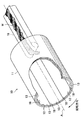
次に、図5を参照して、本実施形態に係るドラム型造粒機10の全体構成について説明する。図5は、本実施形態に係るドラム型造粒機10を示す一部切り欠き斜視図である。なお、図5に示す本実施形態に係るドラム型造粒機10は、図4に示した焼結設備の擬似造粒ライン20、ペレット造粒ライン30に設けられた造粒機24、35に適用可能である。
[1.2. Overall structure of granulator]
Next, with reference to FIG. 5, the whole structure of the
図5に示すように、本実施形態に係るドラム型造粒機10は、円筒形の回転ドラム11内で被造粒物を転動造粒する回転容器型転動造粒機である。ドラム型造粒機10は、円筒形のドラム本体である回転ドラム11と、被造粒物である原料Mを搬送するベルトコンベアなどの搬送機構16と、回転軸Aを中心に回転ドラム11を回転させる回転駆動機構(図示せず。)とを備える。
As shown in FIG. 5, the
回転ドラム11は、例えば、直径1〜5m、長さ5〜25mの円筒形状を有するドラム型容器である。この回転ドラム11は、原料の投入口側が排出口側よりも高くなるように傾斜配置されており、その回転軸Aの水平線に対する傾斜角度θは、例えば、θ=3〜10°である。
The
かかる構成のドラム型造粒機10による造粒時には、上記回転駆動機構により回転ドラム11を所定速度で回転(例えば6.8rpm)させながら、搬送機構16により原料Mを回転ドラム11の一側の投入口から内部に投入する。すると、回転ドラム11内に投入された原料Mは、回転ドラム11内で転動運動しながら、傾斜配置された回転ドラム11の投入口側から他側の排出口まで徐々に移動する。これにより、回転ドラム11内で原料Mが転動造粒されて、所定粒径(例えば数mm)以上の造粒物が製造される。
At the time of granulation by the
上記のようなドラム型造粒機10の造粒処理においては、回転ドラム11の内周面12に対する原料Mの付着を防止して、原料Mの適正な転動造粒を妨げないようにすることが重要である。そこで、回転ドラム11の内周面12には、原料Mの付着を防止するためのライニング材としてゴムライナー13が装着されている。このゴムライナー13は、回転ドラム11の内周面12(以下、ドラム内周面12という。)全体を覆っており、回転ドラム11に対する原料Mの付着を防止して、回転ドラム11の腐食や摩耗を防ぐことができる。
In the granulation process of the
ゴムライナー13は、矩形状のゴムシートからなるライニング材であり、その材質は天然ゴム又は合成ゴムなどのゴムであり、弾力性及び柔軟性を有する。本実施形態では、物理的性質として、例えば、硬度(JIS−A):37〜40°、伸び:740〜810%、引張強さ:21〜26.6MPaのゴムライナー13を使用する。また、一般に市販されているゴムライナー13の製作寸法及び弾性撓み量から、例えば、幅0.3〜1.5m、長さ2〜10mの短冊状のゴムライナー13を使用する。
The
一般に、鉄鉱石原料の造粒に用いられるドラム型造粒機10の回転ドラム11は、直径1〜5m、長さ5〜25mであるので、1枚のゴムライナー13でドラム内周面12全体を覆うことはできない。そこで、本実施形態では、複数枚のゴムライナー13を周方向に継ぎ合わせて、ドラム内周面12全体を覆うようにしている。例えば、図5に示すように、回転ドラム11の周方向に8分割されたゴムライナー13を継ぎ合わせて、8枚のゴムライナー13でドラム内周面12全体を覆っている。このため、回転ドラム11の周方向に相隣接するゴムライナー13、13の間には、回転ドラム11の長手方向(回転軸Aの方向)に延びる継ぎ目18が生じる。
Generally, the
以上のようなゴムライナー13は、リフターと称される固定部材(押さえ板)により、ドラム内周面12に取り付けられる。この固定部材は、上記周方向に相隣接するゴムライナー13、13の継ぎ目18で、ゴムライナー13の周方向端部の継ぎ代をドラム内周面12に固定する(図6参照。)。本実施形態に係るドラム型造粒機10は、かかるゴムライナー13の取り付け構造に特徴を有しており、固定部材をゴムライナー13で覆うことで、固定部材に対する原料の付着を防止する。以下に、本実施形態に係る特徴であるゴムライナー13の取り付け構造について詳述する。
The
[1.3.ゴムライナーの取り付け構造]
次に、図6及び図7を参照して、本実施形態に係るドラム型造粒機10のゴムライナー13の取り付け構造について説明する。図6、図7は、本実施形態に係るゴムライナー13の取り付け構造を示す部分拡大断面図であり、図6は回転ドラム11の底部、図7は上部における取り付け状態を示す。
[1.3. Rubber liner mounting structure]
Next, with reference to FIG.6 and FIG.7, the attachment structure of the
上述した従来の取り付け構造では、図1及び図2に示したように、複数枚のゴムライナー3を周方向に分割して配設し、周方向に相隣接する2枚のゴムライナー3の周方向端部の継ぎ代3aを単純に重ね合わせて、その上部から固定部材4によって、回転ドラム1の内周面2との間に挟み込んで固定していた。しかし、かかる従来の取り付け構造では、固定部材4が露出しているため、図3に示したように固定部材4に原料が固着して、大きな固着物7が形成されてしまうという問題があった。
In the conventional mounting structure described above, as shown in FIGS. 1 and 2, a plurality of
そこで、本実施形態に係るゴムライナー13の取り付け構造では、図6及び図7に示すように、固定部材14に対する原料の固着を防止するため、ゴムライナー13、13の継ぎ目18において、一方のゴムライナー13の周方向端部の継ぎ代13aが、固定部材14を回転ドラム11の内側から巻き込んで覆うように配設されている。
Therefore, in the structure for attaching the
かかるゴムライナー13の取り付け構造について詳述する。図6及び図7に示すように、回転ドラム11の周方向に相隣接するゴムライナー13、13の継ぎ目18ごとに、1本の固定部材14が設置される。固定部材14は、例えば、断面が矩形状の板材(押さえ板)であり、相隣接するゴムライナー13、13の継ぎ目18に沿って、回転ドラム11の長手方向(回転軸A方向)に延びるように設置される。
The mounting structure of the
そして、相隣接するゴムライナー13、13の継ぎ目18において、2つのゴムライナー13、13の周方向端部にある継ぎ代13aの先端部13bは、相互に重なり合うように配置されている。ここで、ゴムライナー13の継ぎ代13aは、複数枚のゴムライナー13を周方向に継ぎ合わせるために必要な帯状部分であり、矩形シート状のゴムライナー13の幅方向の両端にある辺部に相当する。先端部13bは、当該継ぎ代13aの先端にある帯状部分であり、固定部材14に挟み込まれる部分である。
And in the joint 18 of the
固定部材14は、当該重ね合わせられた2つのゴムライナー13の継ぎ代13aの先端部13bを、ドラム内周面12との間に挟み込むように配設される。そして、固定部材14は、2つのゴムライナー13の継ぎ代13aの先端部13bを挟み込んだ状態で、回転ドラム11の外側から取り付けられるボルト15によって、回転ドラム11に対して螺着される。この螺着のために、固定部材14の内部には、ボルト15と螺合するネジ孔14aが形成されている。固定部材14のネジ孔14aにボルト15を締結することで、各々のゴムライナー13は、周方向の両端にある継ぎ代13aが挟持されて、ドラム内周面12に固定される。このようにゴムライナー13と固定部材14を回転ドラム11に固定することで、固定部材14の上面(即ち、ゴムライナー13による被覆面)にボルトやナットを突出して配置しなくて済むので、ゴムライナー13による固定部材14の被覆が容易となる。
The fixing
さらに、本実施形態に係る取り付け構造では、周方向に相隣接するゴムライナー13、13の継ぎ目18において、一方のゴムライナー13(回転方向側のゴムライナー13)の継ぎ代13aは、ドラム内周面12に沿って配設される。これに対し、他方のゴムライナー13(回転方向逆側のゴムライナー13)の継ぎ代13aは、固定部材14を回転ドラム11の内側から巻き込んで覆うように配設される。当該他方のゴムライナー13の継ぎ代13aは、その先端部13bが、回転方向側先端部13bを挟み込んだ状態で、固定部材14と回転ドラム11との間に挟持されて、ドラム内周面12に固定されるが、この先端部13b以外の継ぎ代13a(固定部材14を覆う部分)は、固定部材14に対して固定されておらず、固定部材14に対して接離(当接/離間)可能となっている。図6の例では、固定部材14を覆うゴムライナー13の継ぎ代13aは、断面が略コの字型となっているが、この継ぎ代13aのコの字型部分のうち、固定部材14の側面と上面に隣接する部分は、固定部材14に固定されておらず、固定部材14に対して接離可能である。
Furthermore, in the attachment structure according to the present embodiment, at the joint 18 between the
上記のようにして、ゴムライナー13相互の継ぎ目18において、他方のゴムライナー13の継ぎ代13aが固定部材14を巻き込むようにして覆うことによって、固定部材14に原料が接触しないようにできる。従って、造粒時に、材質的及び形状的に原料が付着しやすい固定部材14に、原料が付着することを確実に防止できる。また、当該継ぎ目18における双方のゴムライナー13の先端部13bは、相互に密着した状態で、固定部材14とドラム内周面12との間に挟み込まれて、原料が両先端部13bの間から侵入することもない。
As described above, at the joint 18 between the
しかも、造粒時には、図6に示すように回転ドラム11の底部に位置していたゴムライナー13は、回転ドラム11の回転に伴って、図7に示すように回転ドラム11の上部に位置づけられる。すると、図7に示すように、弾力性を有するゴムライナー13の周方向中央部13cは、その自重及び付着物の重さにより、回転ドラム11から離隔して、回転ドラム11の内側に向けて凸状となるように変形し(即ち、下方に撓み)、ドラム内周面12とゴムライナー13との間に隙間17が生じる。このため、ゴムライナー13の中央部13cに付着していた原料は、当該中央部13cから離脱して落下するので、ゴムライナー13の中央部13cに対する原料の付着を確実に防止できる。また、より柔軟性を有するゴムライナー13を使用した場合には、当該ゴムライナー13は、回転ドラム11の鉛直方向真上に到達する前に、下方に撓むことができるので、より効率的に付着物を落下させることができる。
Moreover, at the time of granulation, the
さらに、ゴムライナー13が回転ドラム11の上部に移動したときには、ゴムライナー13の両端の継ぎ目18においても、固定部材14を覆っているゴムライナー13の継ぎ代13aが、上記中央部13cの変形に伴って下方に向けて変形し、固定部材14から離隔して、固定部材14と継ぎ代13aの間に隙間19が生じる。即ち、固定部材14を覆っているゴムライナー13の継ぎ代13aは、回転ドラム11の回転に伴って固定部材14に対して接触及び離隔動作する。これにより、固定部材14周辺においてゴムライナー13の継ぎ代13aに付着していた原料も、当該継ぎ代13aが回転ドラム11の上方に移動したとき又はそれより前に、継ぎ代13aから離脱して落下する。従って、周方向に相隣接するゴムライナー13、13の継ぎ目18においても、固定部材14周辺にあるゴムライナー13の継ぎ代13aに対する原料の付着を確実に防止できるので、図3に示した固着物7の問題を解消できる。
Further, when the
以上のように、本実施形態に係るゴムライナー13の取り付け構造によれば、固定部材14に対する原料付着を確実に防止できるとともに、各々のゴムライナー13の中央部13cのみならず、ゴムライナー13の両端部の継ぎ目18においても、原料の付着を好適に防止できる。よって、ゴムライナー13のいずれの箇所においても、原料の固着物が大きく成長することがないので、回転ドラム11内において、固着物により原料を過度に高い位置まで掻き上げてしまうことがない。よって、転動造粒を好適に実施して、適度な粒径の造粒物を安定して製造できる。
As described above, according to the mounting structure of the
さらに、上記ゴムライナー13の取り付け構造におけるリフター機能について説明する。上述したように、ゴムライナー13、13の継ぎ目18では、回転方向逆側のゴムライナー13の継ぎ代13aが固定部材14を覆っており、回転方向側のゴムライナー13の継ぎ代13aは、その下方で、ドラム内周面12に沿って配置されている。このため、回転方向逆側のゴムライナー13の継ぎ代13aにより覆われた固定部材14は、回転方向側のゴムライナー13の継ぎ代13aよりも、回転ドラム11の内側に向けて突出している。即ち、回転方向逆側のゴムライナー13の継ぎ代13aにより覆われた固定部材14と、回転方向側のゴムライナー13の継ぎ代13aとの間には、回転ドラム11の径方向の段差Hがあり、この段差Hは、固定部材14の高さh(リフター高さ)と2枚のゴムライナー13の厚みの和にほぼ等しい。
Furthermore, the lifter function in the mounting structure of the
かかる段差Hは、回転ドラム11の回転時に、回転ドラム11の底部に滞留している原料(図示せず。)を上方に掻き上げるためのリフターとして機能する。このときの原料の掻き上げ量を制御するために、固定部材14の高さhや幅が適正な寸法に設定されている。例えば、固定部材14は、幅100mm、高さ12mmの板材とし、回転ドラム11の底部から回転角90°以下の範囲で原料を掻き上げるようにしてもよい。なお、固定部材14の高さhとは、回転ドラム11に取り付けられた固定部材14の回転ドラム11の径方向の高さであり、例えば、矩形断面を有する板状の固定部材14の場合、その板厚である。
The step H functions as a lifter for scooping up the raw material (not shown) staying at the bottom of the
上記のように、固定部材14の高さhや幅を適正な寸法に設定することにより、ゴムライナー13、13の継ぎ目18にある段差Hによって、回転ドラム11内で適切な量の原料を適切な高さまで掻き上げることができる。従って、回転ドラム11内で原料を好適に転動造粒することができる。以上により、重要な造粒条件である段差Hを、原料の付着という外乱を排除した状態で維持できるため、適正な造粒物を得ることができる。
As described above, by setting the height h and width of the fixing
また、原料の付着性が非常に強いため、リフターによる掻き上げを極力少なくして、転動造粒させたい場合には、回転ドラム11の回転方向を逆にしてもよい。これにより、ゴムライナー13、13の継ぎ目18の段差Hによる原料の掻き上げを無くすことができるので、原料の付着性のみに依存して、原料を掻き上げて転動造粒させることができる。このように、本実施形態に係るドラム型造粒機10は、造粒される原料の付着性の強弱に応じて、回転ドラム11の回転方向を正逆方向に変更することで、多様な種類の原料を適切に転動造粒することができる。
In addition, since the adhesion of the raw material is very strong, the rotational direction of the
[1.4.ゴムライナーの取り付け構造の変形例]
次に、図8を参照して、本実施形態の変更例に係るゴムライナー13の取り付け構造について説明する。図8は、本実施形態の変更例に係るゴムライナー13の取り付け構造(ドラム底部)を示す部分拡大断面図である。
[1.4. Modified example of rubber liner mounting structure]
Next, with reference to FIG. 8, the attachment structure of the
上記図6及び図7の例では、矩形断面を有する板状の固定部材14を用いたが、図8の例では、円形断面を有する丸棒状の固定部材14を用いている。図8に示すように、回転ドラム11の周方向に相隣接するゴムライナー13、13の継ぎ目18において、両ゴムライナー13の継ぎ代13aの先端部13bを相互に重ね合わせて、丸棒状の固定部材14とドラム内周面12との間に挟み込んで固定する。丸棒状の固定部材14には、上記と同様に、ボルト15と螺合するネジ孔14aが形成されており、回転ドラム11の外側からボルト15を、回転ドラム11及び2枚のゴムライナー13を貫通させて、固定部材14に締結することで、固定部材14が回転ドラム11に螺着される。
6 and 7, the plate-like fixing
さらに、2枚のゴムライナー13、13の継ぎ目18において、回転方向逆側のゴムライナー13の継ぎ代13aは、丸棒状の固定部材14を巻き込んで覆うように配設されている。これにより、丸棒状の固定部材14に対する原料の付着を防止できる。また、回転ドラム11が回転して、ゴムライナー13が回転ドラム11の上部に移動したときには、上記図7と同様に、ゴムライナー13が下方に撓むことで、ゴムライナー13の中央部13c及び継ぎ目18付近に付着した原料を好適に落下させることができる。
Further, in the joint 18 between the two
以上、図8に示した丸棒状の固定部材14を用いたゴムライナー13の取り付け構造においても、上記図6及び図7で説明した矩形断面の固定部材14を用いた場合と同等の作用効果を得ることができる。なお、固定部材14の断面形状は、上述した矩形、円形の例に限定されず、台形、三角形その他の多角形、楕円、半円など、任意の形状を使用できる。
As described above, the
<2.第2の実施形態>
次に、本発明の第2の実施形態に係るゴムライナー13の取り付け構造について説明する。なお、第2の実施形態に係るドラム型造粒機は、以下に説明する取り付け構造を除いては、上記第1の実施形態に係るドラム型造粒機10の機能構成と略同一であるので、その詳細説明は省略する。
<2. Second Embodiment>
Next, the attachment structure of the
[2.1.ゴムライナーの取り付け構造]
図9は、本発明の第2の実施形態に係るゴムライナー13の取り付け構造(ドラム底部)を示す部分拡大断面図である。図9に示す取り付け構造は、ゴムライナー13の継ぎ目18におけるリフターを全く排除して、原料の付着をできる限り少なくした例である。
[2.1. Rubber liner mounting structure]
FIG. 9 is a partially enlarged cross-sectional view showing the
図9に示すように、回転ドラム11の周方向に相隣接するゴムライナー13A、13Bの継ぎ目18ごとに、2本の固定部材14A、14Bが、回転ドラム11の長手方向に対して平行に並設される。固定部材14A、14Bは、同一の高さh及び幅を有する矩形断面の板材である。
As shown in FIG. 9, two fixing
そして、一方のゴムライナー13Aの周方向端部の継ぎ代13aは、一方の固定部材14Aを回転ドラム11の内側から巻き込んで覆うように配設され、当該ゴムライナー13Aの継ぎ代13aの先端部13bは、固定部材14Aとドラム内周面12との間に挟み込まれて固定される。この固定部材14Aにボルト15Aを締結することで、固定部材14Aがゴムライナー13Aの継ぎ代13aの先端部13bと密着した状態で回転ドラム11に螺着される。
The
同様に、他方のゴムライナー13Bの周方向端部の継ぎ代13aは、他方の固定部材14Bを回転ドラム11の内側から巻き込んで覆うように配設され、当該ゴムライナー13Bの継ぎ代13aの先端部13bは、固定部材14Bとドラム内周面12との間に挟み込まれて固定される。この固定部材14Bにボルト15Bを締結することで、固定部材14Bがゴムライナー13Bの継ぎ代13aの先端部13bと密着した状態で回転ドラム11に螺着される。
Similarly, the joint 13a at the circumferential end of the
この結果、ゴムライナー13A、13Bの継ぎ目18において、各々のゴムライナー13A、13Bの継ぎ代13aは、固定部材14A、14Bの三辺を囲むように略コの字型の断面形状となり、それぞれの先端部13bが回転ドラム11に固定される。また、ゴムライナー13Aの継ぎ代13aとゴムライナー13Bの継ぎ代13aのうち、上記2本の固定部材14A、14Bの間に挟み込まれた部分は、相互に密着して、面接触している。このため、当該密着したゴムライナー13A、13Bの継ぎ目18から、原料が侵入することはない。
As a result, in the joint 18 of the
また、固定部材14Aと固定部材14Bの高さhが同一であるため、継ぎ目18におけるゴムライナー13Aと13Bの上面(回転ドラム11内側の面)は、ほぼ面一となっており、段差がない。これにより、ドラム内周面12全体を、円滑なライニング面となるように被覆でき、継ぎ目18における固定部材14A、14Bのリフター機能を無くすことができる。
Further, since the height h of the fixing
以上のようなゴムライナー13の取り付け構造により、ゴムライナー13A、13Bの継ぎ目18における段差を全く排除して、リフター機能を弱めることで、当該継ぎ目18における原料の付着を、限りなく低減することができる。従って、掻き上げによる転動造粒に対する阻害要因を、限界まで低減することができる。このような取り付け構造は、原料の付着性が非常に強いため、リフターによる原料の掻き上げ機能を極力少なくしたい場合に有効である。この場合には、ゴムライナー13に対する原料の付着性のみに依存して、原料を掻き上げて、転動造粒が行われる。
By attaching the
また、図9に示す取り付け構造においても、ゴムライナー13A、13Bの継ぎ代13aにより、それぞれ固定部材14A、14Bを覆っているので、固定部材14A、14Bに対する原料の付着を防止できる。また、回転ドラム11が回転して、ゴムライナー13A、13Bが回転ドラム11の上部に移動したときには、上記図7と同様に、ゴムライナー13A、13Bが下方に撓むことで、ゴムライナー13A、13Bの中央部13c及び継ぎ目18付近の継ぎ代13aに付着した原料を好適に落下させることができる。
Also, in the mounting structure shown in FIG. 9, the fixing
[2.2.ゴムライナーの取り付け構造の変形例]
次に、図10を参照して、第2の実施形態の変更例に係るゴムライナー13の取り付け構造について説明する。図10は、本実施形態の変更例に係るゴムライナー13の取り付け構造(ドラム底部)を示す部分拡大断面図である。
[2.2. Modified example of rubber liner mounting structure]
Next, with reference to FIG. 10, the attachment structure of the
図10に示す取り付け構造は、原料の掻き上げ量を調整するために、2つの固定部材14A、14Bの高さ(板圧)hAとhBに差をつけて、ゴムライナー13A、13Bの継ぎ目18に段差Hを設けた例である。
In the mounting structure shown in FIG. 10, in order to adjust the scraping amount of the raw material, the height (plate pressure) h A and h B of the two fixing
図10の取り付け構造は、固定部材14A、14Bの高さに差をつけた点以外は、図9の取り付け構造と略同一であるので、重複説明は省略する。図10に示すように、相隣接するゴムライナー13A、13Bの継ぎ目18において、回転方向側のゴムライナー13Aを固定する固定部材14Aの高さhAよりも、回転方向逆側のゴムライナー13Bを固定する固定部材14Bの高さhBの方が高い。これにより、回転方向逆側のゴムライナー13Bの継ぎ代13aにより覆われた固定部材14Bは、回転方向側のゴムライナー13Aの継ぎ代13aにより覆われた固定部材14Aよりも、回転ドラム11の内側に向けて突出しており、その段差Hは、固定部材14Bと固定部材14Aの高さhの差(hB−hA)である。
Since the attachment structure of FIG. 10 is substantially the same as the attachment structure of FIG. 9 except that the heights of the fixing
かかる段差Hは、回転ドラム11の回転時に、回転ドラム11の底部に滞留している原料(図示せず。)を上方に掻き上げるためのリフターとして機能する。このときの原料の掻き上げ量を制御するために、固定部材14A、14Bの高さhA、hBが適正な寸法に設定される。例えば、原料の付着性が低いため、段差Hによる原料の掻き上げ量を多くしたい場合には、段差Hを大きくする。一方、原料の付着性が高いため、段差Hによる原料の掻き上げ量を少なくしたい場合には、段差Hを小さくする。このように固定部材14A、14Bの高さhA、hBを変化させて、段差Hの高さを調整することで、原料の掻き上げ量を適正値に制御できる。よって、原料の付着性等に応じた適切な掻き上げ量で原料を掻き上げて、原料を適正に転動造粒できる。
The step H functions as a lifter for scooping up the raw material (not shown) staying at the bottom of the
<3.第3の実施形態>
次に、本発明の第3の実施形態に係るゴムライナー13の取り付け構造について説明する。なお、第3の実施形態に係るドラム型造粒機は、以下に説明する取り付け構造を除いては、上記第1の実施形態に係るドラム型造粒機10の機能構成と略同一であるので、その詳細説明は省略する。
<3. Third Embodiment>
Next, the attachment structure of the
[3.1.ゴムライナーの取り付け構造]
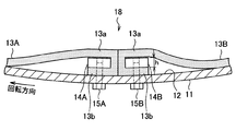
図11は、本発明の第3の実施形態に係るドラム型造粒機10の全体構成を示す一部切り欠き斜視図である。図12は、本実施形態に係るドラム型造粒機10の全体構成を示す縦断面図である。図13は、本実施形態に係る回転ドラム11の長手方向及び周方向にゴムライナー13を継ぎ合わせた状態を示す斜視図である。
[3.1. Rubber liner mounting structure]
FIG. 11 is a partially cutaway perspective view showing the entire configuration of the
上述したように、一般に市販されているゴムライナー13は、例えば、幅0.3〜1.5m、長さ2〜10mであるので、大型のドラム型造粒機10において回転ドラム11の長手方向の長さが長いとき(例えば25m)には、1枚物のゴムライナー13で回転ドラム11の全長に渡ってカバーできない場合がある。かかる場合には、図11及び図12に示すように、ドラム内周面12全体を覆うためには、回転ドラム11の周方向のみならず、長手方向にも、複数枚のゴムライナー13を継ぎ合わせる必要が生じる。図示の例では、回転ドラム11の周方向に8分割、長手方向に3分割して、複数枚のゴムライナー13を継ぎ合わせて配設している。
As described above, the commercially
このように回転ドラム11の長手方向に複数枚のゴムライナー13を継ぎ合わせる場合、当該長手方向に相隣接するゴムライナー13、13の継ぎ目51から、原料が入り込まないように、当該継ぎ目51を被覆する必要がある。そこで、本実施形態では、図11〜図13に示すように、回転ドラム11の長手方向に相隣接するゴムライナー13、13の継ぎ目51に対して、ドラム内周面12の全周にわたって帯状の被覆材50を装着して、当該継ぎ目51を塞ぐようにしている。この帯状の被覆材50の材質は、ゴムライナー13と同様のゴム製とすることが好ましいが、他の材質を使用することもできる。
When a plurality of
また、ドラム内周面12の全周をカバー可能な一枚物の帯状の被覆材50を使用して、継ぎ目51に沿って接着すれば、継ぎ目51からの原料の漏れを確実に防止できる。しかし、この場合には、ドラム内周面12に全てのゴムライナー13を取り付けた後でなければ、帯状の被覆材50を取り付けることができないという欠点がある。この欠点を解決するためには、ゴムライナー13の取り付け前に予め、ゴムライナー13の幅と同程度の長さの帯状の被覆材50を用意し、各々のゴムライナー13の長さ方向の一側端部に当該帯状の被覆材50を一部はみ出した残した状態で接着しておく。そして、ゴムライナー13の取り付け時に、長手方向に隣接するゴムライナー13、13の継ぎ目51を帯状の被覆材50で覆うようにして、個々のゴムライナー13を取り付けていく。
Further, if a single belt-
例えば、図13の例では、原料の流れの上流側のゴムライナー13Cの端部に、予め帯状の被覆材50を接着しておく。そして、原料の流れの下流側のゴムライナー13Dを設置した後に、原料の流れの上流側のゴムライナー13Cを設置する。このとき、継ぎ目51からの原料の侵入を確実に防ぐためには、原料の流れの下流側のゴムライナー13Dに対して、ゴムライナー13Cからはみ出している帯状の被覆材50を接着した方が、好ましい。しかし、回転ドラム11内に投入された原料が、ゴムライナー13Cから帯状の被覆材50を超えてゴムライナー13Dに達した後に、原料の流れに逆らって、帯状の被覆材50とゴムライナー13Dとの隙間から侵入する可能性は低いので、ゴムライナー13Dに帯状の被覆材50を接着しなくてもよい。
For example, in the example of FIG. 13, a strip-shaped
以上、第3の実施形態に係るゴムライナー13の取り付け構造について説明した。本実施形態によれば、回転ドラム11の長手方向全体にわたって一枚物のゴムライナー13を設置できないため、当該長手方向に複数枚のゴムライナー13を継ぎ合わせる場合であっても、その継ぎ目51を帯状の被覆材50により好適に塞ぐことができる。よって、継ぎ目51からの原料の侵入を適切に防止できる。
Heretofore, the attachment structure of the
次に、本発明の実施例に係るドラム型造粒機を用いて造粒を行い、ドラム内周面に対する原料の付着状況を観察した実験結果について説明する。なお、以下の実施例で用いる実験条件は、本発明のゴムライナーの付着防止材としての機能を確認するための例示であり、本発明が以下の実施例に限定されるものではない。 Next, a description will be given of experimental results obtained by performing granulation using the drum type granulator according to the embodiment of the present invention and observing the adhesion state of the raw material to the drum inner peripheral surface. The experimental conditions used in the following examples are illustrations for confirming the function of the rubber liner of the present invention as an adhesion preventing material, and the present invention is not limited to the following examples.
まず、本発明の比較例として、ドラム型造粒機の回転ドラム1の内周面2に対して周方向に9分割したゴムライナー3を図1及び図2に示した取り付け構造に従って装着し、かかるドラム型造粒機を用いて原料を造粒する実験を行った。ゴムライナー3としては、物性値が異なる2種類のゴムライナー(第1及び第2のゴムライナー)を使用した。
First, as a comparative example of the present invention, a
また、本発明の実施例として、上記第1の実施形態に従い、ドラム型造粒機の回転ドラム11の内周面12に対して周方向に9分割したゴムライナー13を図5及び図6に示した取り付け構造に従って装着し、かかるドラム型造粒機を用いて原料を造粒する実験を行った。ゴムライナー13としては、比較例と同様に、物性値が異なる2種類のゴムライナー(第1及び第2のゴムライナー)を使用した。
Further, as an example of the present invention, according to the first embodiment, a
比較例及び実施例の実験条件は以下の通りである。
被造粒物 :鉄鉱石原料(マラバンバ鉱石、高燐ブロックマン鉱石等)
鉄鉱石原料の粒度分布 :粒径250μm以下の粒子が60質量%以上
鉄鉱石原料の含有水分 :造粒時で9質量%
回転ドラム :直径φ=3m、長さL=10m、傾きθ=7°
回転ドラムの回転数 :6.8rpm
固定部材 :高さ12mm、幅100mm、長さ10m
第1及び第2のゴムライナー :天然ゴム製の矩形状ゴムシート
第1及び第2のゴムライナーの寸法 :ゴム厚6mm、幅1.2m、長さ10m
第1のゴムライナーの物性値 :硬度(JIS−A)37°、伸び810%、引張強さ26.6MPa
第2のゴムライナーの物性値 :硬度(JIS−A)40°、伸び740%、引張強さ21MPa
The experimental conditions of the comparative example and the example are as follows.
Granulated material: Iron ore raw materials (Malabamba ore, high phosphorus block man ore, etc.)
Particle size distribution of iron ore material: 60% by mass or more of particles having a particle size of 250 μm or less Moisture content of iron ore material: 9% by mass at the time of granulation
Rotating drum: Diameter φ = 3m, length L = 10m, inclination θ = 7 °
Number of rotations of rotating drum: 6.8 rpm
Fixed member: Height 12mm, width 100mm, length 10m
First and second rubber liners: Rectangular rubber sheet made of natural rubber Dimensions of first and second rubber liners:
Physical property values of first rubber liner: Hardness (JIS-A) 37 °, elongation 810%, tensile strength 26.6 MPa
Physical property value of second rubber liner: Hardness (JIS-A) 40 °, elongation 740%, tensile strength 21 MPa
まず、比較例に係る実験結果について説明する。比較例によれば、ゴムライナー3の表面には、問題となる厚みで原料が付着することはなかったが、固定部材4(リフター部)には、50mm以上の厚みで固着物7が固着し、円滑な転動造粒が阻害された。
First, experimental results according to the comparative example will be described. According to the comparative example, the raw material did not adhere to the surface of the
即ち、固定部材4周辺の固着物7が、ドラム内側に突出した堰のようになり、造粒時には、回転ドラム1の回転に合わせて原料が固着物7の堰の部分を乗り越えるため、原料の円滑な転動運動が阻害された。さらに、この固着物7により原料の掻き上げ量及び掻き上げ高さが激しくなり、必要以上に掻き上げられた原料が、回転ドラム1の回転に合わせて高い位置から落下するため、造粒物を破壊してしまうこととなった。
That is, the fixed
加えて、大きく成長した固着物7が自重に抗しきれずに剥がれ落ち、大塊がドラム型造粒機から排出された。本比較例に係る焼結設備では、ドラム型造粒機出側に大塊用の破砕機を設置しており、固着物7の大塊を破砕した後に次工程に搬送したため、焼結設備の運転を継続できたが、破砕物が細粒となって造粒粒度が確保されないなどの問題が生じた。
In addition, the
次に、本発明の実施例に係る実験結果について説明する。本実施例によれば、上記2種類のゴムライナー(第1及び第2のゴムシート)のいずれの場合にも、ゴムライナー13で覆われた固定部材14周辺(リフター部)に対する原料の付着が顕著に減少した。リフター部においては、リフター部間のゴムライナー13の表面と同様に、原料の付着を薄皮程度(厚さ10mm以下の付着)に抑えることができ、円滑な転動造粒を行うことができた。
Next, experimental results according to examples of the present invention will be described. According to the present embodiment, in both cases of the two types of rubber liners (first and second rubber sheets), the raw material adheres to the periphery of the fixing member 14 (lifter portion) covered with the
このように、本実施例では、リフター部に大きな固着物7が形成されないので、固着物7による過剰な原料の掻き上げを防止できた。また、回転ドラム11内上部からの造粒物の落下量も削減でき、造粒物の落下による崩壊を抑制することができた。従って、回転ドラム11内で原料を適正に転動造粒することができるので、造粒品質の向上に大きく寄与することとなる。
Thus, in this example, since the large fixed
[効果]
以上、本発明の好適な実施形態及び実施例に係るドラム型造粒機10とその造粒方法について説明した。本実施形態によれば、回転ドラム11の周方向に隣接するゴムライナー13、13の継ぎ目18において、原料が付着しにくい材質のゴムライナー13の継ぎ代13aにより、固定部材14を巻き込むようにして覆う。これにより、回転ドラム11内で材質的及び形状的に原料が付着しやすい固定部材14を露出しないようにできるので、継ぎ目18における固定部材14に対する原料の付着を確実に防止できる。さらに、回転ドラム11の回転に伴って、各ゴムライナー13がドラム内上部に移動したときに、弾力性を有するゴムライナー13が下方に撓むように変形するので、ゴムライナー13の表面に付着した原料を落下させ、付着物を除去できる。さらに、かかる変形に伴い、ゴムライナー13、13の継ぎ目18においても、固定部材14を覆うゴムライナー13の継ぎ代13aが固定部材14から離隔するように変形するので、当該継ぎ目18における付着物をも好適に落下させて除去できる。
[effect]
In the above, the
従って、回転ドラム11内の固定部材14周辺(リフター部)において、従来の取り付け構造のような大きな固着物7の形成を防止できる。よって、当該固定部材14周辺(リフター部)による原料の掻き上げ量及び掻き上げ高さを適正値に調整できるので、原料を適正に転動造粒することができ、適正な粒径の均一な造粒物を安定して製造できる。
Therefore, it is possible to prevent the formation of a large fixed
以上説明したように、本実施形態によれば、リフター部に対する原料の付着を防止することで、回転ドラム11内で原料を適正に転動造粒して造粒物を製造できるので、焼結機40に投入する際に必要な粒度の均一な造粒物を提供できる。その結果、焼結機40の生産性の向上および焼結鉱の品質向上に寄与できる。
As described above, according to the present embodiment, since the raw material is prevented from adhering to the lifter portion, the raw material can be appropriately rolled and granulated in the
また、ドラム型造粒機10に出側に篩選別装置を設置し、この篩選別装置により粒度の大きな造粒物を取り除いて、ドラム型造粒機10入側に戻して、再度造粒を行うことがある。本実施形態によれば、ドラム型造粒機10にて安定した造粒を行うことができるので、上記再度造粒する量を軽減、或いは、無くすことが可能となる。これにより、ドラム型造粒機10に投入する原料量を軽減でき、ドラム型造粒機10のみならず、その前後の搬送装置を含めて、装置能力が課題となることを防止できる。例えば、上記篩選別装置の設置自体を省略可能な場合もあり、ランニングコスト面からも効果は非常に大きいものとなる。
In addition, a sieve sorting device is installed on the outlet side of the
また、従来のドラム型造粒機では、回転ドラム1に対する原料の付着が原因で、回転ドラム1を回転させる回転駆動機構のパワー(例えばモータのパワー)が不足することもあった。しかし、本実施形態によれば、回転ドラム11に対する原料の付着量を大幅に低減でるので、上記回転駆動機構のパワー不足の問題も解消できる。
Moreover, in the conventional drum type granulator, the power (for example, the power of the motor) of the rotary drive mechanism that rotates the rotary drum 1 may be insufficient due to the adhesion of the raw material to the rotary drum 1. However, according to this embodiment, the amount of raw material attached to the
以上、添付図面を参照しながら本発明の好適な実施形態について詳細に説明したが、本発明はかかる例に限定されない。本発明の属する技術の分野における通常の知識を有する者であれば、特許請求の範囲に記載された技術的思想の範疇内において、各種の変更例または修正例に想到し得ることは明らかであり、これらについても、当然に本発明の技術的範囲に属するものと了解される。 The preferred embodiments of the present invention have been described in detail above with reference to the accompanying drawings, but the present invention is not limited to such examples. It is obvious that a person having ordinary knowledge in the technical field to which the present invention pertains can come up with various changes or modifications within the scope of the technical idea described in the claims. Of course, it is understood that these also belong to the technical scope of the present invention.
例えば、上記実施形態では、原料の付着防止用のライニング材として、ゴムシートからなるゴムライナー13を単独で用いたが、本発明はかかる例に限定されない。例えば、ゴムライナーの表面にポリテトラフルオロエチレン(テフロン(登録商標))材質の被覆シートを貼り合わせた二層構造のライニング材を用いてもよい。これにより、被覆シートが設けられたゴムライナー表面に対して、原料がより付着しにくくなる。また、ゴムライナーの表面に対して、例えば梨地状の微細な凹凸模様を形成することで、当該表面が円滑面である場合よりも、原料の付着を好適に防止できる。
For example, in the above embodiment, the
また、上記実施形態では、ゴムライナー13により矩形断面の固定部材14を覆う場合には、ゴムライナー13が略直角に折れ曲がったコーナー部が形成されていた(図6、7、9、10等参照。)。そこで、このようなゴムライナー13のコーナー部を補強するために、補強材(例えば、帆布、薄い鋼材など)を当該コーナー部の内側に装着してもよい。これにより、回転ドラムの回転に伴って繰り返し動く可動部分であるコーナー部を補強できる。
Moreover, in the said embodiment, when covering the fixing
また、上記実施形態では、本発明のドラム型造粒機を、図4に示す焼結設備の造粒機24、35に適用し、焼結原料を造粒する例について説明した。しかし、本発明は、かかる例に限定されず、各種の原料、食品など任意の被造粒物を造粒するための各種のドラム型造粒機に適用できるものである。 Moreover, in the said embodiment, the drum type granulator of this invention was applied to the granulators 24 and 35 of the sintering equipment shown in FIG. 4, and the example which granulates a sintering raw material was demonstrated. However, the present invention is not limited to such examples, and can be applied to various drum-type granulators for granulating arbitrary materials to be granulated such as various raw materials and foods.
7 固着物
10 ドラム型造粒機
11 回転ドラム
12 内周面
13 ゴムライナー
13a 継ぎ代
13b 先端部
14 固定部材
15 ボルト
16 搬送機構
17、19 隙間
18 周方向に隣接するゴムライナーの継ぎ目
50 帯状の被覆材
51 長手方向に隣接するゴムライナーの継ぎ目
M 原料
A 回転軸
H 段差
h 固定部材の高さ(リフター高さ)
DESCRIPTION OF
Claims (9)
矩形状のゴムシートからなり、前記回転ドラムの内周面全体を覆うように前記回転ドラムの周方向に継ぎ合わせて配置される複数枚のゴムライナーと、
前記ゴムライナーを前記回転ドラムの内周面に固定する複数本の固定部材と、
を備え、
前記固定部材は、前記周方向に相隣接する前記ゴムライナーの継ぎ目に沿って、前記回転ドラムの長手方向に対して平行に配設され、前記周方向に相隣接する前記ゴムライナーの継ぎ代を、前記回転ドラムの内周面との間に挟み込むようにして前記回転ドラムの内周面に固定し、
前記周方向に相隣接する前記ゴムライナーの継ぎ目において、少なくとも一方のゴムライナーの継ぎ代は、前記固定部材を巻き込むように覆うことを特徴とする、ドラム型造粒機。 A cylindrical rotating drum;
A plurality of rubber liners, which are made of a rectangular rubber sheet and are arranged to be joined together in the circumferential direction of the rotating drum so as to cover the entire inner peripheral surface of the rotating drum;
A plurality of fixing members for fixing the rubber liner to the inner peripheral surface of the rotating drum;
With
The fixing member is disposed in parallel to the longitudinal direction of the rotating drum along a seam of the rubber liners adjacent to each other in the circumferential direction, and has a joint margin between the rubber liners adjacent to each other in the circumferential direction. , And fixed to the inner peripheral surface of the rotating drum so as to be sandwiched between the inner peripheral surface of the rotating drum,
The drum-type granulator according to claim 1, wherein at a joint of the rubber liners adjacent to each other in the circumferential direction, a joint of at least one of the rubber liners is covered so as to involve the fixing member.
前記周方向に相隣接する前記ゴムライナーの継ぎ目において、一方のゴムライナーの継ぎ代は、前記回転ドラムの内周面に沿って配設され、他方のゴムライナーの継ぎ代は、前記固定部材を巻き込むように覆い、
前記周方向に相隣接する前記ゴムライナーの継ぎ代の先端部は、相互に重なり合うように配置され、前記1本の固定部材と前記回転ドラムの内周面との間に挟み込まれて前記回転ドラムの内周面に固定されることを特徴とする、請求項1又は2に記載のドラム型造粒機。 One fixing member is installed for each joint of the rubber liners adjacent to each other in the circumferential direction,
In the joint of the rubber liners adjacent to each other in the circumferential direction, the joint margin of one rubber liner is disposed along the inner peripheral surface of the rotating drum, and the joint margin of the other rubber liner is the fixing member. Cover it like a roll,
The front ends of the joint margins of the rubber liners adjacent to each other in the circumferential direction are arranged so as to overlap each other, and are sandwiched between the one fixed member and the inner peripheral surface of the rotary drum. The drum type granulator according to claim 1 or 2, wherein the drum type granulator is fixed to the inner peripheral surface of the drum.
前記他方のゴムライナーの継ぎ代により覆われた前記固定部材により、前記回転ドラム内の被造粒物を掻き上げることを特徴とする、請求項3に記載のドラム型造粒機。 The one rubber liner is a rubber liner disposed on the rotation direction side of the rotating drum, and the other rubber liner is a rubber liner disposed on the rotation direction opposite side of the rotation drum,
The drum type granulator according to claim 3, wherein the granulated material in the rotating drum is scraped up by the fixing member covered by the joint margin of the other rubber liner.
前記周方向に相隣接する前記ゴムライナーの継ぎ目において、一方のゴムライナーの継ぎ代と他方のゴムライナーの継ぎ代とが、前記2本の固定部材の間で相互に接触するように配設され、
前記一方のゴムライナーの継ぎ代は、前記2本の固定部材のうちの一方の固定部材を巻き込むように覆い、当該継ぎ代の先端部は、前記一方の固定部材と前記回転ドラムの内周面との間に挟み込まれて前記回転ドラムの内周面に固定され、
前記他方のゴムライナーの継ぎ代は、前記2本の固定部材のうちの他方の固定部材を巻き込むように覆い、当該継ぎ代の先端部は、前記他方の固定部材と前記回転ドラムの内周面との間に挟み込まれて前記回転ドラムの内周面に固定されることを特徴とする、請求項1又は2に記載のドラム型造粒機。 Two fixing members are juxtaposed for each joint of the rubber liners adjacent to each other in the circumferential direction,
In the joint of the rubber liners adjacent to each other in the circumferential direction, the joint of one rubber liner and the joint of the other rubber liner are disposed so as to contact each other between the two fixing members. ,
The joint margin of the one rubber liner covers the one fixing member of the two fixing members so as to be wound around, and the tip end portion of the joint margin is the inner peripheral surface of the one fixing member and the rotating drum. And is fixed to the inner peripheral surface of the rotating drum,
The seam allowance of the other rubber liner covers the other fixing member of the two fixing members so as to be wound around, and the tip of the seam allowance is the inner peripheral surface of the other fixing member and the rotating drum. The drum type granulator according to claim 1, wherein the drum type granulator is fixed to an inner peripheral surface of the rotating drum.
前記他方の固定部材の前記回転ドラムの径方向の高さは、前記一方の固定部材の前記回転ドラムの径方向の高さよりも高く、
前記他方のゴムライナーの継ぎ代により覆われた前記他方の固定部材と、前記一方のゴムライナーの継ぎ代により覆われた前記一方の固定部材との段差により、前記回転ドラム内の被造粒物を掻き上げることを特徴とする、請求項6に記載のドラム型造粒機。 The one rubber liner is a rubber liner disposed on the rotation direction side of the rotating drum, and the other rubber liner is a rubber liner disposed on the rotation direction opposite side of the rotation drum,
The radial height of the rotating drum of the other fixing member is higher than the radial height of the rotating drum of the one fixing member,
A granulated object in the rotating drum is formed by a step between the other fixing member covered by the joint of the other rubber liner and the one fixing member covered by the joint of the one rubber liner. The drum type granulator according to claim 6, wherein the drum type granulator is scraped up.
回転ドラムを回転させて前記被造粒物を造粒する際に、固定部材により前記回転ドラムの内周面に取り付けられた各ゴムライナーが、前記回転ドラムの回転に伴って上方に移動したときに、前記回転ドラムの内側に向けて断面凸状に変形することによって、前記ゴムライナーに付着した前記被造粒物を離脱させることを特徴とする、造粒方法。
A granulation method for granulating a granulated product using the drum type granulator according to any one of claims 1 to 8,
When each of the rubber liners attached to the inner peripheral surface of the rotating drum by the fixing member moves upward with the rotation of the rotating drum when rotating the rotating drum to granulate the granulated material. Further, the granulation method is characterized in that the granulated material adhering to the rubber liner is released by being deformed into a convex cross section toward the inside of the rotating drum.
Priority Applications (1)
| Application Number | Priority Date | Filing Date | Title |
|---|---|---|---|
| JP2009086611A JP5009331B2 (en) | 2009-03-31 | 2009-03-31 | Drum type granulator and granulation method |
Applications Claiming Priority (1)
| Application Number | Priority Date | Filing Date | Title |
|---|---|---|---|
| JP2009086611A JP5009331B2 (en) | 2009-03-31 | 2009-03-31 | Drum type granulator and granulation method |
Publications (2)
| Publication Number | Publication Date |
|---|---|
| JP2010234304A JP2010234304A (en) | 2010-10-21 |
| JP5009331B2 true JP5009331B2 (en) | 2012-08-22 |
Family
ID=43089176
Family Applications (1)
| Application Number | Title | Priority Date | Filing Date |
|---|---|---|---|
| JP2009086611A Active JP5009331B2 (en) | 2009-03-31 | 2009-03-31 | Drum type granulator and granulation method |
Country Status (1)
| Country | Link |
|---|---|
| JP (1) | JP5009331B2 (en) |
Families Citing this family (2)
| Publication number | Priority date | Publication date | Assignee | Title |
|---|---|---|---|---|
| JP2012086130A (en) * | 2010-10-18 | 2012-05-10 | Kobe Steel Ltd | Drum type granulator |
| CN106693834A (en) * | 2016-12-19 | 2017-05-24 | 四川雷鸣生物环保工程有限公司 | Ball maker |
Family Cites Families (5)
| Publication number | Priority date | Publication date | Assignee | Title |
|---|---|---|---|---|
| JPS619706Y2 (en) * | 1979-09-22 | 1986-03-28 | ||
| JPS5912739A (en) * | 1982-07-13 | 1984-01-23 | Kawasaki Steel Corp | Drum type mixer |
| JPS59186638A (en) * | 1983-04-07 | 1984-10-23 | Kawasaki Steel Corp | Drum mixer |
| JPS60171546U (en) * | 1984-04-24 | 1985-11-13 | 日立造船株式会社 | Drum Granulator with Cantilever Rubber Panel |
| JP2005007280A (en) * | 2003-06-18 | 2005-01-13 | Ochi Kensetsu Kk | Compaction granulator and artificial aggregate manufacturing method and artificial aggregate manufacturing system using the compaction granulator |
-
2009
- 2009-03-31 JP JP2009086611A patent/JP5009331B2/en active Active
Also Published As
| Publication number | Publication date |
|---|---|
| JP2010234304A (en) | 2010-10-21 |
Similar Documents
| Publication | Publication Date | Title |
|---|---|---|
| JP3902629B2 (en) | Pretreatment method of sintering raw materials | |
| KR101171455B1 (en) | Method for production of carbon composite metal oxide briquette | |
| JP5326592B2 (en) | Granulation method of sintering raw material | |
| WO2006120773A1 (en) | Method for pretreatment of raw materials for sintering | |
| JP5009331B2 (en) | Drum type granulator and granulation method | |
| US8206487B2 (en) | Method for producing carbon composite metal oxide briquettes | |
| JP4786508B2 (en) | Pretreatment method of sintering raw material | |
| JP4659144B2 (en) | Binder addition method, binder addition apparatus, kneader and kneading method | |
| JP4786760B2 (en) | Pretreatment method of sintering raw material | |
| TW536555B (en) | Pretreatment apparatus for raw materials for production of reduced iron | |
| KR20110128901A (en) | Method of crushing iron ore material | |
| US20080143026A1 (en) | Material for Coating Iron Ore Pelletizing Disks and Drums and a Constructive Arrangement for Pelletizing Disks and Drums | |
| JP2023049317A (en) | Trommel | |
| JP4677040B2 (en) | Granulation method of fine powder raw material | |
| CN210394476U (en) | Breaking and mixing machine | |
| JP7234712B2 (en) | Powder agglomerate and method for producing powder agglomerate | |
| KR20020048152A (en) | Dust pellet producting appratus and its method as raw material of sinter cake | |
| JP6841256B2 (en) | Granulated product, method for producing granulated product and method for producing sintered ore | |
| JP5103919B2 (en) | Method for producing granulated material for metallurgical raw materials | |
| JP2006312786A (en) | Method for pretreating raw material for sintering | |
| CN220537877U (en) | Large-sized cylindrical pelletizer for improving quality of chrome ore pellets | |
| KR102498593B1 (en) | Granulated product, manufacturing method of granulated product, and manufacturing method of sintered ore | |
| CN210187677U (en) | Screening plant of zinc-containing waste residue sand | |
| JP5928731B2 (en) | Manufacturing method and apparatus for granulating raw material for sintering | |
| JPS6020419Y2 (en) | pin granulator |
Legal Events
| Date | Code | Title | Description |
|---|---|---|---|
| A621 | Written request for application examination |
Free format text: JAPANESE INTERMEDIATE CODE: A621 Effective date: 20110215 |
|
| A977 | Report on retrieval |
Free format text: JAPANESE INTERMEDIATE CODE: A971007 Effective date: 20120425 |
|
| TRDD | Decision of grant or rejection written | ||
| A01 | Written decision to grant a patent or to grant a registration (utility model) |
Free format text: JAPANESE INTERMEDIATE CODE: A01 Effective date: 20120508 |
|
| A01 | Written decision to grant a patent or to grant a registration (utility model) |
Free format text: JAPANESE INTERMEDIATE CODE: A01 |
|
| A61 | First payment of annual fees (during grant procedure) |
Free format text: JAPANESE INTERMEDIATE CODE: A61 Effective date: 20120530 |
|
| R151 | Written notification of patent or utility model registration |
Ref document number: 5009331 Country of ref document: JP Free format text: JAPANESE INTERMEDIATE CODE: R151 |
|
| FPAY | Renewal fee payment (event date is renewal date of database) |
Free format text: PAYMENT UNTIL: 20150608 Year of fee payment: 3 |
|
| FPAY | Renewal fee payment (event date is renewal date of database) |
Free format text: PAYMENT UNTIL: 20150608 Year of fee payment: 3 |
|
| S533 | Written request for registration of change of name |
Free format text: JAPANESE INTERMEDIATE CODE: R313533 |
|
| FPAY | Renewal fee payment (event date is renewal date of database) |
Free format text: PAYMENT UNTIL: 20150608 Year of fee payment: 3 |
|
| R350 | Written notification of registration of transfer |
Free format text: JAPANESE INTERMEDIATE CODE: R350 |
|
| S533 | Written request for registration of change of name |
Free format text: JAPANESE INTERMEDIATE CODE: R313533 |
|
| R350 | Written notification of registration of transfer |
Free format text: JAPANESE INTERMEDIATE CODE: R350 |