JP5007182B2 - Hair iron - Google Patents
Hair iron Download PDFInfo
- Publication number
- JP5007182B2 JP5007182B2 JP2007234840A JP2007234840A JP5007182B2 JP 5007182 B2 JP5007182 B2 JP 5007182B2 JP 2007234840 A JP2007234840 A JP 2007234840A JP 2007234840 A JP2007234840 A JP 2007234840A JP 5007182 B2 JP5007182 B2 JP 5007182B2
- Authority
- JP
- Japan
- Prior art keywords
- barrel
- hair
- needle
- negative ions
- hair iron
- Prior art date
- Legal status (The legal status is an assumption and is not a legal conclusion. Google has not performed a legal analysis and makes no representation as to the accuracy of the status listed.)
- Active
Links
- XEEYBQQBJWHFJM-UHFFFAOYSA-N Iron Chemical compound [Fe] XEEYBQQBJWHFJM-UHFFFAOYSA-N 0.000 title claims description 100
- 210000004209 hair Anatomy 0.000 title claims description 79
- 229910052742 iron Inorganic materials 0.000 title claims description 48
- 150000002500 ions Chemical class 0.000 claims description 65
- 230000002093 peripheral effect Effects 0.000 claims description 16
- 239000000463 material Substances 0.000 claims description 13
- 229920003002 synthetic resin Polymers 0.000 claims description 7
- 239000000057 synthetic resin Substances 0.000 claims description 7
- 229910052751 metal Inorganic materials 0.000 claims description 3
- 239000002184 metal Substances 0.000 claims description 3
- 230000001747 exhibiting effect Effects 0.000 claims description 2
- 230000007246 mechanism Effects 0.000 description 9
- 229920006092 Strator® Polymers 0.000 description 7
- 230000000630 rising effect Effects 0.000 description 6
- 230000009471 action Effects 0.000 description 4
- 229910000838 Al alloy Inorganic materials 0.000 description 2
- 239000004677 Nylon Substances 0.000 description 2
- 230000000694 effects Effects 0.000 description 2
- 230000004048 modification Effects 0.000 description 2
- 238000012986 modification Methods 0.000 description 2
- 229920001778 nylon Polymers 0.000 description 2
- 230000007480 spreading Effects 0.000 description 2
- 238000013517 stratification Methods 0.000 description 2
- 238000004804 winding Methods 0.000 description 2
- 230000008901 benefit Effects 0.000 description 1
- 238000007664 blowing Methods 0.000 description 1
- 230000008859 change Effects 0.000 description 1
- 238000010586 diagram Methods 0.000 description 1
- 230000003700 hair damage Effects 0.000 description 1
- 238000010438 heat treatment Methods 0.000 description 1
- 238000009413 insulation Methods 0.000 description 1
- 230000007257 malfunction Effects 0.000 description 1
Images


Landscapes
- Brushes (AREA)
Description
本発明は、ヘアーアイロンに関し、さらに詳細には、マイナスイオンを発生する手段を備えたヘアーアイロンに関するものである。 The present invention relates to a hair iron, and more particularly to a hair iron provided with means for generating negative ions.
マイナスイオンは、髪に当てれば、髪の損傷を抑えるとともに、髪をサラサラにしてセットをやりやすくすると同時に、セットの持ちも良くなるなどの効果があると言われている。 Negative ions are said to be effective when applied to hair, as well as reducing hair damage, making the hair smoother and easier to set, and improving the holding of the set.
そこで、特開2003−275013号公報では、マイナスイオンを発生するヘアーアイロンが提案されている。 Therefore, Japanese Patent Application Laid-Open No. 2003-275013 proposes a hair iron that generates negative ions.
このヘアーアイロンは、髪を巻き付ける発熱面を周囲に形成した円筒形の発熱部と直列に棒状のハンドルを設けたもので、前記棒状のハンドル内には高電圧発生手段とその高電圧発生手段に接続された放電電極を備えている。また、その放電電極で発生したマイナスイオンは、前記ハンドルに設けた放出口(一箇所)から発熱部に向けて放出するようになっている。
しかしながら、上記のヘアーアイロンでは、ハンドル部分に設けた一箇所の放出口からマイナスイオンを放出するようにしているので、例えば、髪を伸ばすために発熱面で髪を梳かすようにすれば髪全体にマイナスイオンを行き渡らせることができるが、発熱面に髪を巻き付けてカールをする場合は、放出口からのマイナスイオンの大部分は、巻き付けた外側の髪の、しかも、その髪の表面にしか当たらない。そのため、熱のダメージを最も受ける発熱面に直接巻き付けられた一番内側の髪にまで十分にマイナスイオンを行き渡らせることのできない問題がある。 However, in the above-described hair iron, negative ions are released from one discharge port provided in the handle portion. For example, if the hair is combed on the heat generating surface to stretch the hair, the entire hair However, when curling by curling hair around the heat generating surface, most of the negative ions from the discharge port are only on the outer surface of the wound and on the surface of the hair. I won't win. Therefore, there is a problem that the negative ions cannot be sufficiently distributed to the innermost hair directly wound around the heat generating surface that is most damaged by heat.
この問題を解決するため、特開2006−204369号では、髪を巻き付ける発熱面を周囲に形成した金属製で円筒形の発熱部と直列に設けた棒状のハンドル内に、高電圧発生手段を備えるとともに、前記高電圧発生手段のグランド出力を前記発熱部の円筒と接続し、一方、高電圧発生手段の高電圧出力と接続した針状の電極を発熱部の円筒内に配置して円筒の内周と対向させて配置し、その円筒内に配置した針電極の針先と対向する円筒の発熱面に複数のスリットあるいは貫通孔を設けたヘアーアイロンが提案されている。
しかしながら、上記した特開2006−204369号公報に開示されたヘアーアイロンにあっては、マイナスイオンの放出口が円筒の発熱部の長手方向の一部にしか設けられていないので、円筒状の発熱部の長手方向に拡がった毛髪のうち、放出口を外れた毛髪には、マイナスイオンが当たらないという問題がある。また、マイナスイオンは熱に弱いので、針状電極から放出されたマイナスイオンは、円筒状の発熱部に設けた放出口から僅かしか外部に放出されず、マイナスイオンの効果が薄いという問題がある。 However, in the above-described hair iron disclosed in Japanese Patent Application Laid-Open No. 2006-204369, the negative ion discharge port is provided only in a part of the longitudinal direction of the heat generating portion of the cylinder. Among the hairs that have spread in the longitudinal direction of the part, there is a problem that negative ions do not hit the hair that is off the discharge port. In addition, since negative ions are weak to heat, there is a problem that the negative ions emitted from the needle-like electrode are only slightly released to the outside from the discharge port provided in the cylindrical heat generating portion, and the negative ions are less effective. .
そこで、本発明は、アイロンの長手方向に沿って拡がった毛髪に満遍なくマイナスイオンを供給することができるとともに、充分な量のマイナスイオンを外部放出することのできるヘアーアイロンを提供することを目的とするものである。 Accordingly, an object of the present invention is to provide a hair iron that can uniformly supply negative ions to hair that has spread along the longitudinal direction of the iron and that can release a sufficient amount of negative ions to the outside. To do.
上記課題は、本発明の下記(1)〜(3)の構成のいずれかによるヘアーアイロンにより解決することができる。
(1) 一方が他方に対して離接できるように揺動可能な細長い下側バレルおよび上側バレルを備え、前記下側バレルおよび上側バレルのそれぞれの接合面は、両者協働して毛髪のためのストレーター機能を発揮するためのものであり、一方、前記下側バレルおよび上側バレルのそれぞれの外周面は、両者協働して毛髪のためのカール機能を発揮するためのものであり、前記下側バレルは、金属で形成され、垂直部と、この垂直部の一端に形成され、該下側バレルの接合面を構成する第1水平部と、前記垂直部の他端に形成され、該下側バレルの外周面の一部を構成する第2水平部を有し、バレルの長手方向に延びる骨格材、および合成樹脂で形成され、前記骨格材の垂直部の両側に配置され、該骨格材に沿って延びるほぼ台形の第1および第2バレルバーを備え、これらの第1および第2バレルバーには、それぞれ該バレルバーに沿って延びる細長いイオン放電板が埋設されており、該イオン放電板には、間隔を置いて配置され、バレル外方に向いたマイナスイオン放出用の複数の針状突起が設けられており、前記第1および第2バレルバーの少なくとも前記針状突起が配置された部分は、バレル外部に開放した空間が設けられていることを特徴とするヘアーアイロン。
(2) 前記グリップの先端中央部に、マイナスイオンを放出するための針状電極が配置されており、この針状電極により、下側バレルの接合面と上側バレルの接合面の間にマイナスイオンを吹き出すようになっている上記(1)のヘアーアイロン。
(3) 前記上側バレルの外周面に離接可能な揺動可能な細長いクリップ板を更に有する上記(1)または(2)のヘアーアイロン。
The said subject can be solved by the hair iron by either of the structure of following (1)-( 3 ) of this invention.
( 1 ) An elongate lower barrel and an upper barrel that are swingable so that one side can be separated from and attached to the other are provided, and the respective joint surfaces of the lower barrel and the upper barrel cooperate with each other for hair. On the other hand, the respective outer peripheral surfaces of the lower barrel and the upper barrel are for exhibiting a curling function for hair in cooperation with each other, The lower barrel is formed of metal, is formed at a vertical portion, at one end of the vertical portion, is formed at a first horizontal portion that constitutes a joining surface of the lower barrel, and at the other end of the vertical portion, A skeleton material having a second horizontal portion constituting a part of the outer peripheral surface of the lower barrel and extending in the longitudinal direction of the barrel, and a synthetic resin, disposed on both sides of the vertical portion of the skeleton material, A substantially trapezoidal first and extending along the material; The first and second barrel bars are each embedded with an elongated ion discharge plate extending along the barrel bar. The ion discharge plates are spaced apart from each other, A plurality of needle-like projections for emitting negative ions facing the surface are provided, and at least a portion of the first and second barrel bars where the needle-like projections are arranged is provided with a space opened outside the barrel. A hair iron characterized by that.
( 2 ) A needle-like electrode for releasing negative ions is disposed at the center of the tip of the grip, and the needle-like electrode causes negative ions to be interposed between the joint surface of the lower barrel and the joint surface of the upper barrel. The hair iron according to (1) above.
( 3 ) The hair iron according to (1) or (2), further including a swingable and slender clip plate that can be attached to and detached from the outer peripheral surface of the upper barrel.
本発明のヘアーアイロンにおいては、上記したように、上記バレルの長手方向に沿って延びるイオン放電板に長手方向に間隔を置いて配置した複数の針状電極からマイナスイオンを放出するようにしているので、上記バレルの長手方向に拡がった毛髪全体にマイナスイオンが行き渡るという効果がある。
また、本発明のヘアーアイロンにおいては、針状電極の周囲が比較的温度の低い合成樹脂で囲まれており、発生したマイナスイオンが高温の部材に接触しないので、マイナスイオンが破壊されることなく、効率的に毛髪まで到達し、効率がよい。
In the hair iron of the present invention, as described above, negative ions are emitted from a plurality of needle-like electrodes arranged at intervals in the longitudinal direction on an ion discharge plate extending along the longitudinal direction of the barrel. Therefore, there is an effect that negative ions are spread over the entire hair spreading in the longitudinal direction of the barrel.
Further, in the hair iron of the present invention, the needle-shaped electrode is surrounded by a relatively low temperature synthetic resin, and the generated negative ions do not contact the high-temperature member, so that the negative ions are not destroyed. , Reach the hair efficiently, good efficiency.
以下、添付図面を参照しつつ、本発明の実施の態様によるヘアーアイロンについて説明する。 Hereinafter, a hair iron according to an embodiment of the present invention will be described with reference to the accompanying drawings.
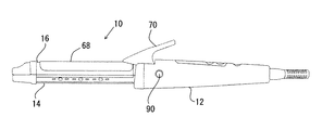
本発明の実施の態様によるヘアーアイロン10は、グリップ12、このグリップの先端に取り付けられた下側バレル14、およびこの下側バレル14に後端側で揺動可能に取り付けられた上側バレル16を備えている。この下側バレル14と上側バレル16でアイロン部を構成する。前記下側バレル14および上側バレル16は、互いに接合した接合位置(図1参照)と、一方が他方に対して揺動して、互いに離れた離間位置(図2参照)とを取ることができる。上記上側バレル16は、上記接合位置(図1参照)を取るようバネ(図示せず)によって常時下側バレル14側に付勢されている。
A
上記前記下側バレル14および上側バレル16のそれぞれの接合面18、20(図3参照)は、両者協働して毛髪のためのストレーター機能(毛髪をストレートにする機能)を発揮するためのものであり、一方、前記下側バレル14および上側バレル16のそれぞれの外周面22、24は、両者協働して毛髪のためのカール機能(毛髪にカールを付ける機能)を発揮するためのものである。図示していないが、通常の発熱体が、上側バレル16に設けられているが、下側バレル14にも設けられていてもよい。
The joint surfaces 18 and 20 (see FIG. 3) of the
前記下側バレル14は、金属特にアルミニウム合金で形成され、バレルの長手方向に該バレルのほぼ全長に亘って延びる骨格材26、および合成樹脂(例えばナイロン等の断熱性の良いものが好ましい)で形成され、前記骨格材26に沿って延びる第1および第2バレルバー28、30を備えている。
The
前記骨格材26は、垂直部32と、この垂直部32の上端に形成され、前記下側バレル14の接合面18を構成する第1水平部34と、前記垂直部32の下端に形成され、該下側バレル14の外周面22の一部を構成する第2水平部36を有している。
The
前記第1および第2バレルバー28、30は、それぞれ前記骨格材26の垂直部32の両側と第1水平部34と第2水平部36で囲まれた空間に配置されており、横断面形状はほぼ台形をしている。前記第1および第2バレルバー28,30の外部に露出した面は、下側バレル14の外周面の残部(一部は上記したように前記第2水平部36が構成している)を構成している。したがって、この外部に露出した面は、湾曲している。
The first and
ヘアーアイロン10は、マイナスイオン発生装置を備えている。このマイナスイオン発生装置は、前記第1および第2バレルバー28、30に埋設され、それぞれ該バレルバーに沿ってほぼ水平に延びる細長い第1および第2イオン放電板38、40(図4参照)を有している。これらの第1および第2イオン放電板38、40の外方を向いた側縁には、それぞれ間隔を置いて配置され、バレル外方に向いたマイナスイオン放出用の複数の針状突起42、44が設けられている。これらの針状突起は、一枚のイオン放電板について、図示したように3個程度設けることが好ましい。
The
前記第1および第2バレルバー28、30の少なくとも前記針状突起42、44が配置された部分には、図3に示されているように開口46、48によりバレル外部に開放した空間50、52が設けられて、前記針状突起42、44が発生したマイナスイオンをバレル外部に放出するようになっている。
In at least portions of the first and
また、前記グリップ12の先端中央部には、マイナスイオンを放出するための針状電極54が露出した状態で配置されている(図4参照)。この針状電極54は、下側バレル14の接合面18と上側バレル16の接合面20の間にマイナスイオンを吹き出すためのものである。上側バレル16の接合面20のバレル幅方向中央には、バレルのほぼ全長に亘って延びる断面半円径の溝状凹部56(図3参照)が形成されていることが好ましい。この凹部56により、下側バレル14の接合面18と上側バレル16の接合面20の間に、バレルのほぼ全長に亘って延びる空間58が形成され、針状電極54から放出されたマイナスイオンが、この空間58を通ってバレルの先端まで届くようになる。この針状電極54からのマイナスイオンは、主としてストレーター機能時に、下側バレルと上側バレルの間に挟まれた毛髪に作用する。
Further, a needle-
前記第1および第2イオン放電板38、40および針状電極54は、それぞれリード60、62、64を介して高電圧発生装置66に接続されており、この高電圧発生装置66から高電圧を供給されて、マイナスイオンを発生するようになっている。上記したように、針状電極54からのマイナスイオンは、主としてストレーター機能時に、下側バレルと上側バレルの間に挟まれた毛髪に作用し、第1および第2イオン放電板38、40の針状突起42、44からのマイナスイオンは、主としてカール機能時に、下側バレルと上側バレルの周りに巻かれた毛髪に作用する。針状突起42、44からのマイナスイオンは、また、ストレーター機能時に、下側バレルと上側バレルの間に挟まれてスライドさせられる毛髪にアイロン部の前後で作用する。
The first and second
前記下側バレル14の後端側には、前記上側バレル16の外周面24に沿って湾曲して延びる細長いクリップ板68が、揺動可能に取り付けられ、前記上側バレル16の外周面24に対して離接可能になっている。このクリップ板68は、バネ(図示せず)により前記上側バレル16の外周面24方向に常時付勢されている。このクリップ板68の後端には、該クリップ板68を上記バネの付勢力に抗して前記上側バレル16の外周面24から離す方向に揺動させるためのレバー70が一体的に形成されている。本明細書では、レバー70をクリップ板68の一部とする。
On the rear end side of the
本ヘアーアイロン10は、上記レバー70が操作されたとき、上記クリップ板68を開くようにする(図5参照)カール機能設定位置と、上側バレル16(クリップ板68とともに)開くようにする(図2参照)ストレーター機能設定位置との間で切り替えるための切替機構72を備えている。
The
図6および図7に示されているように、上記上側バレル16およびクリップ板68は二股状となったそれぞれの後部16a、16b、68a、68bで、グリップ12に固定された下側バレル14の後部両側部に設けられたに2枚の立ち上がり部14a、14bに支軸73により揺動可能に取り付けられている。
As shown in FIGS. 6 and 7, the
上記切替機構72は、図8に最も良く示されているように、下側バレル14の立ち上がり部14a、14bに設けられた上下方向に延びる長穴74、76、上側バレル16の後部16a、16bに設けられた丸穴78、80、クリップ板68の後部68a、68bに設けられた上下方向に延びる長穴82、84、これらの長穴74、76、丸穴78、80、長穴82、84を通って横方向に延びるスイッチバー86、およびグリップ12を形成する壁部12aに対向して設けられた開口に配置された一対のプッシュボタン88、90(図6、図7参照)を備えている。上記スイッチバー86およびプッシュボタン88、90は、一直線上に並べられ、スイッチバー86の両端はプッシュボタン88、90の内側に接触しているが、後に説明する目的のため、スイッチバー86はプッシュボタン88、90に対して移動できるようになっている。プッシュボタン88、90の内側端縁には、環状のフランジ88a、90aが設けられていて、該プッシュボタン88、90が、グリップ12外部に飛び出さないようになっている。図6および図7に示したように、この切替機構72は、グリップ12の先端部に設けて、グリップ12の使用者が通常握らない位置にスイッチバー86が配置されるようにする。
As best shown in FIG. 8, the
クリップ板68の後部68a、68bは、それぞれグリップ12の壁部12aから内側に僅かな間隔(クリップ板間隔という)をおいて配置されており、スイッチバー86の長さは、グリップ12の両側部の壁部12a、12aの間の内側の幅より上記のクリップ板間隔(一つの)分短くされており、スイッチバー86は、グリップ12の内部で、このクリップ板間隔の分だけ左右(図6および図7において、下側を左、上側を右とする)にストロークできるようになっている。スイッチバー86の左側へのストロークに対してはプッシュボタン90がストッパーとして働き、スイッチバー86の右側へのストロークに対してはプッシュボタン88がストッパーとして働く。
The
上記スイッチバー86は、全体としては細長い丸棒であるが、以下に説明するような3つの縮径部を有している。すなわち、スイッチバー86は、その右側端部が第1縮径部86aとされており、そしてクリップ板68の厚さ分だけ通常の径となっており、続いて図6に示したように下側バレル14の立ち上がり部14aの厚み分の幅の第2縮径部86bとされている。上記スイッチバー86には、さらに左側端部にクリップ板68の後部16bの厚み分の通常径部を残し、それに続いて図7に示したようにクリップ板68の後部16bの厚み分の幅の第3縮径部86cとされている。
The
下側バレル14の立ち上がり部14a、14bに設けられた上下方向に延びる長穴74、76は、上部にスイッチバー86の通常の径部が納まることのできる丸穴部74a、76aを、そしてそこから下方に延び、幅が上記スイッチバー86の第2および第3縮径部86b、86cの径より僅かに大きく、通常の径部の径より小さい長穴部74b、76bを有している(丸穴部74a、長穴部74bについては図示していない)。上側バレル16の後部16a、16bに設けられた丸穴78、80は、上部にスイッチバー86の通常の径部が納まることのできる径を有している。クリップ板68の後部68a、68bに設けられた上下方向に延びる長穴82、84は、下部にスイッチバー86の通常の径部が納まることのできる丸穴部82a、84aを、そしてそこから上方に延び、幅が上記スイッチバー86の第1および第3縮径部86b、86cの径より僅かに大きく、通常の径部の径より小さい長穴部82b、84bを有している(丸穴部82a、長穴部82bについては図示していない)。本ヘアーアイロン10の図1に示した状態(全てが閉じた状態)において、長穴74、76の丸穴部74a、76a、丸穴78、80、長穴82、84の丸穴部82a、84aは、一直線上に整列される。
The vertically extending
つぎに、図6および図7を参照して、図2に示したように上側バレル16(クリップ板68は一体的になる)を下側バレル14に対して上方に揺動させることができるようにするストレーター機能設定位置、および図5に示したようにクリップ板68を上側バレル16(下側バレル14は一体的になる)に対して上方に揺動させることができるようにするカール機能設定位置について説明する。
Next, referring to FIG. 6 and FIG. 7, as shown in FIG. 2, the upper barrel 16 (the
先ず、ストレーター機能設定位置について説明する。このストレーター機能設定位置は、左側のプッシュボタン90を押し込むことにより行われる。このプッシュボタン90の押し込みにより、スイッチバー86は右方向に移動し、これとともにプッシュボタン88はグリップ12から突出するが、プッシュボタン88のフランジ88aの作用により、プッシュボタン88およびスイッチバー86は、図6に示した位置でストップする。
First, the strator function setting position will be described. This strator function setting position is performed by pressing the
スイッチバー86は図6に示す位置では、その通常の径部がクリップ板68の長穴82、84の丸穴部82a、84aの位置に位置する一方、第2縮径部86bおよび第3縮径部86cが下側バレル14の長穴74、76の位置に位置する。従って、レバー70を下方に回動すると、スイッチバー86の第2縮径部86bおよび第3縮径部86cが下側バレル14の長穴74、76の長穴部74b、76bに入り込んで下方に移動することにより、上側バレル16がクリップ板68を伴って上方に揺動させられ、図2の位置を取る。使用者は、この位置で毛髪を下側バレル14および上側バレル16の間に位置させ、レバー70を離すことにより、上側バレル16がバネの作用により自動的に下方に揺動して閉じ、下側バレル14および上側バレル16で毛髪を挟み込んで、ヘアーアイロン10がストレーター機能を発揮できるようになる。
In the position shown in FIG. 6, the
次に、カール機能設定位置について説明する。このカール機能設定位置は、右側のプッシュボタン88を押し込むことにより行われる。このプッシュボタン88の押し込みにより、スイッチバー86は左方向に移動し、これとともにプッシュボタン90はグリップ12から突出するが、プッシュボタン90のフランジ90aの作用により、プッシュボタン90およびスイッチバー86は、図7に示した位置でストップする。
Next, the curl function setting position will be described. This curl function setting position is performed by pressing the
スイッチバー86は図7に示す位置では、その通常の径部が下側バレル14の長穴74、76の丸穴部74a、76aの位置に位置する一方、第1縮径部86aおよび第3縮径部86cがクリップ板68の長穴82、84の位置に位置する。従って、レバー70を下方に回動すると、スイッチバー86の第1縮径部86aおよび第3縮径部86cがクリップ板68の長穴82、84の長穴部82a、84bに入り込んで下方に移動することにより、クリップ板68のみが上方に揺動させられ、図5の位置を取る。使用者は、この位置で毛髪をクリップ板68および上側バレル16の間に位置させ、レバー70を離すことにより、クリップ板68がバネの作用により自動的に下方に揺動して閉じ、クリップ板68および上側バレル16で毛髪を挟み込んで、ヘアーアイロン10がカール機能を発揮できるようになる。
In the position shown in FIG. 7, the
以上の切替機構72によれば、一つの操作部でストレーター機能設定位置およびカール機能設定位置に設定切り替えができ、使用者が操作しやすいという利点がある。また、ストレーター機能設定位置およびカール機能設定位置での開閉機構を1つに集約したことで、部品を少なくし、サイズをコンパクトにすることが可能となった。さらに、スイッチバーを通常握らない部分に配置したことで、誤動作を抑制することができるようになった。
According to the
以上説明した本ヘアーアイロン10で用いられたマイナスイオン発生装置の構造は、カール機能のみのヘアーアイロン(すなわち、バレルが下側バレルと上側バレルに分かれておらず、断面円形のもの)にも使用できる。そのヘアーアイロンを本発明のヘアーアイロンの変形例として、図9を参照して、以下簡単に説明する。
The structure of the negative ion generator used in the
この変形例のヘアーアイロン100は、上記の例のヘアーアイロン10と比べて、バレルが下側バレルと上側バレルに分かれておらず、断面円形となっている点、バレルバーに骨格材が無い点、および針状電極が無い点で異なっているが、その他の構造はほぼ同様である。ヘアーアイロン100は、グリップ(図示せず)に取り付けられ、アイロン部を形成する断面円形のバレル102を有している。このバレル102主要部は、アルミニウム合金等でできている。
Compared with the
上記バレル102の表面側の少なくとも一箇所に、バレル102の長手方向に延びる合成樹脂で形成されたバレルバー104が配置されている。この合成樹脂としては、ナイロン等が好ましい。このバレルバー104には、該バレルバーに沿って延びる細長いイオン放電板106、108が埋設されている。本例では、バレルバーとして、一部品の形態のものを示したが、イオン放電板106、108のそれぞれ用として2部品のものであってもよい。すなわち、バレルバー104は分割されていてもよい。これらのイオン放電板106、108は、上記したイオン放電板38、40と同じ構造を有するものであり、上記したイオン放電板38、40と同じく、イオン放電板の長手方向に間隔を置いて配置され、バレル外方に向いたマイナスイオン放出用の複数の針状突起110、112が設けられている。
A
前記バレルバー104の少なくとも前記針状突起110、112が配置された部分には、図9に示されているように開口114、116によりバレル外部に開放した空間118、120が設けられて、前記針状突起110、112が発生したマイナスイオンをバレル外部に放出するようになっている。
At least a portion of the
前記イオン放電板106、108は、それぞれリード(図示せず)を介して高電圧発生装置(図示せず)に接続されており、この高電圧発生装置から高電圧を供給されて、マイナスイオンを発生するようになっている。
The
本ヘアーアイロン100も、上記の例のヘアーアイロン10のクリップ板68と同様の構造のクリップ板122を有している。このクリップ板122も前記バレル102の上部外周面に離接可能なように揺動可能である。このクリップ板122の操作は、クリップ板68の場合と同様にレバー(図示せず)によって行われる。なお、図9のバレル内部には発熱体等が配置されるが、それらは省略して示した。
The
本発明によるヘアーアイロンによれば、上記したように、上記バレルの長手方向に沿って延びるイオン放電板に長手方向に間隔を置いて配置した複数の針状電極からマイナスイオンを放出するようにしているので、上記バレルの長手方向に拡がった毛髪全体にマイナスイオンが行き渡るという効果がある。また、本発明のヘアーアイロンにおいては、針状電極の周囲が比較的温度の低い合成樹脂で囲まれており、発生したマイナスイオンが高温の部材に接触しないので、マイナスイオンが破壊されることなく、効率的に毛髪まで到達し、効率がよい。また、グリップがカール時、ストレート時において変化しないため、持ち替えることなく切り替えができ、切り替えによるヘアーセットがスムーズに移行できる。 According to the hair iron of the present invention, as described above, negative ions are emitted from a plurality of needle-like electrodes arranged at intervals in the longitudinal direction on an ion discharge plate extending along the longitudinal direction of the barrel. Therefore, there is an effect that negative ions are spread throughout the hair spreading in the longitudinal direction of the barrel. Further, in the hair iron of the present invention, the needle-shaped electrode is surrounded by a relatively low temperature synthetic resin, and the generated negative ions do not contact the high-temperature member, so that the negative ions are not destroyed. , Reach the hair efficiently, good efficiency. In addition, since the grip does not change when curled or straight, it can be switched without changing, and the hair set by switching can be smoothly transferred.
10 ヘアーアイロン
12 グリップ
14 下側バレル
14a 立ち上がり部
14b 立ち上がり部
16 上側バレル
16a 後部
16b 後部
18 接合面
20 接合面
22 外周面
24 外周面
26 骨格材
28 バレルバー
30 バレルバー
32 垂直部
34 第1水平部
36 第2水平部
38 第1イオン放電板
40 第2イオン放電板
42 針状突起
44 針状突起
46 開口
48 開口
50 空間
52 空間
54 針状電極
56 凹部
58 空間
60 リード
62 リード
64 リード
66 高電圧発生装置
68 クリップ板
68a 後部
68b 後部
70 レバー
72 切替機構
73 支軸
74 長穴
74a 丸穴部
74b 長穴部
76 長穴
76a 丸穴部
76b 長穴部
78 丸穴
80 丸穴
82 長穴
82a 丸穴部
82b 長穴部
84 長穴
84a 丸穴部
84b 長穴部
86 スイッチバー
86a 第1縮径部
86b 第2縮径部
86c 第3縮径部
88 プッシュボタン
88a フランジ
90 プッシュボタン
90a フランジ
DESCRIPTION OF
Claims (3)
Priority Applications (1)
| Application Number | Priority Date | Filing Date | Title |
|---|---|---|---|
| JP2007234840A JP5007182B2 (en) | 2007-09-11 | 2007-09-11 | Hair iron |
Applications Claiming Priority (1)
| Application Number | Priority Date | Filing Date | Title |
|---|---|---|---|
| JP2007234840A JP5007182B2 (en) | 2007-09-11 | 2007-09-11 | Hair iron |
Publications (3)
| Publication Number | Publication Date |
|---|---|
| JP2009066022A JP2009066022A (en) | 2009-04-02 |
| JP2009066022A5 JP2009066022A5 (en) | 2009-07-09 |
| JP5007182B2 true JP5007182B2 (en) | 2012-08-22 |
Family
ID=40602929
Family Applications (1)
| Application Number | Title | Priority Date | Filing Date |
|---|---|---|---|
| JP2007234840A Active JP5007182B2 (en) | 2007-09-11 | 2007-09-11 | Hair iron |
Country Status (1)
| Country | Link |
|---|---|
| JP (1) | JP5007182B2 (en) |
Families Citing this family (2)
| Publication number | Priority date | Publication date | Assignee | Title |
|---|---|---|---|---|
| JP5377082B2 (en) * | 2009-06-02 | 2013-12-25 | 株式会社テスコム | Hair iron |
| JP5619394B2 (en) * | 2009-08-24 | 2014-11-05 | 株式会社テスコム | Hair iron |
Family Cites Families (2)
| Publication number | Priority date | Publication date | Assignee | Title |
|---|---|---|---|---|
| US6996916B2 (en) * | 2004-03-09 | 2006-02-14 | Helen Of Troy Limited | Variable ion hair styling appliances |
| JP3594959B2 (en) * | 2004-04-15 | 2004-12-02 | 九州日立マクセル株式会社 | Hair treatment equipment |
-
2007
- 2007-09-11 JP JP2007234840A patent/JP5007182B2/en active Active
Also Published As
| Publication number | Publication date |
|---|---|
| JP2009066022A (en) | 2009-04-02 |
Similar Documents
| Publication | Publication Date | Title |
|---|---|---|
| JP2009054315A5 (en) | ||
| US20160166037A1 (en) | Hair care device | |
| BR0015897B1 (en) | process for improving the impregnation of a hair styling composition, process for increasing hair volume, process for increasing hair diameter, and process for enhancing hair restylability. | |
| JP5007182B2 (en) | Hair iron | |
| CA112413S (en) | Actuator cap | |
| US5513665A (en) | Hair curling apparatus | |
| JP3194584U (en) | Eyelash curler dryer | |
| JP5260776B2 (en) | Hair iron | |
| JP2006528798A5 (en) | ||
| JP2004522929A5 (en) | ||
| JP2004529021A5 (en) | ||
| JP5114139B2 (en) | Hair iron | |
| JP2004255207A (en) | Steam hair setter | |
| US20160374445A1 (en) | Hair iron | |
| WO2014132297A1 (en) | Hair iron with comb | |
| JP5619394B2 (en) | Hair iron | |
| JP2011056141A (en) | Hair dryer | |
| JP2006026805A5 (en) | ||
| JP5377082B2 (en) | Hair iron | |
| JP3165668U (en) | hair iron | |
| JP2006204369A (en) | Hair iron | |
| Singer | The population surprise | |
| JP3112287U (en) | Hair curlers | |
| JP4616328B2 (en) | Hair stopper | |
| JP4124463B2 (en) | Simple Anma tools |
Legal Events
| Date | Code | Title | Description |
|---|---|---|---|
| RD04 | Notification of resignation of power of attorney |
Free format text: JAPANESE INTERMEDIATE CODE: A7424 Effective date: 20090331 |
|
| A521 | Request for written amendment filed |
Free format text: JAPANESE INTERMEDIATE CODE: A523 Effective date: 20090408 |
|
| AA91 | Notification that invitation to amend document was cancelled |
Free format text: JAPANESE INTERMEDIATE CODE: A971091 Effective date: 20090526 |
|
| A621 | Written request for application examination |
Free format text: JAPANESE INTERMEDIATE CODE: A621 Effective date: 20100706 |
|
| A977 | Report on retrieval |
Free format text: JAPANESE INTERMEDIATE CODE: A971007 Effective date: 20120126 |
|
| A131 | Notification of reasons for refusal |
Free format text: JAPANESE INTERMEDIATE CODE: A131 Effective date: 20120207 |
|
| A521 | Request for written amendment filed |
Free format text: JAPANESE INTERMEDIATE CODE: A523 Effective date: 20120403 |
|
| TRDD | Decision of grant or rejection written | ||
| A01 | Written decision to grant a patent or to grant a registration (utility model) |
Free format text: JAPANESE INTERMEDIATE CODE: A01 Effective date: 20120515 |
|
| A01 | Written decision to grant a patent or to grant a registration (utility model) |
Free format text: JAPANESE INTERMEDIATE CODE: A01 |
|
| A61 | First payment of annual fees (during grant procedure) |
Free format text: JAPANESE INTERMEDIATE CODE: A61 Effective date: 20120528 |
|
| FPAY | Renewal fee payment (event date is renewal date of database) |
Free format text: PAYMENT UNTIL: 20150601 Year of fee payment: 3 |
|
| R150 | Certificate of patent or registration of utility model |
Free format text: JAPANESE INTERMEDIATE CODE: R150 Ref document number: 5007182 Country of ref document: JP Free format text: JAPANESE INTERMEDIATE CODE: R150 |
|
| R250 | Receipt of annual fees |
Free format text: JAPANESE INTERMEDIATE CODE: R250 |
|
| R250 | Receipt of annual fees |
Free format text: JAPANESE INTERMEDIATE CODE: R250 |
|
| R250 | Receipt of annual fees |
Free format text: JAPANESE INTERMEDIATE CODE: R250 |
|
| R250 | Receipt of annual fees |
Free format text: JAPANESE INTERMEDIATE CODE: R250 |
|
| R250 | Receipt of annual fees |
Free format text: JAPANESE INTERMEDIATE CODE: R250 |
|
| R250 | Receipt of annual fees |
Free format text: JAPANESE INTERMEDIATE CODE: R250 |
|
| R250 | Receipt of annual fees |
Free format text: JAPANESE INTERMEDIATE CODE: R250 |
|
| R250 | Receipt of annual fees |
Free format text: JAPANESE INTERMEDIATE CODE: R250 |
|
| R250 | Receipt of annual fees |
Free format text: JAPANESE INTERMEDIATE CODE: R250 |
|
| R250 | Receipt of annual fees |
Free format text: JAPANESE INTERMEDIATE CODE: R250 |