JP5007005B2 - Communication antenna covering a large ground area - Google Patents
Communication antenna covering a large ground area Download PDFInfo
- Publication number
- JP5007005B2 JP5007005B2 JP2001200441A JP2001200441A JP5007005B2 JP 5007005 B2 JP5007005 B2 JP 5007005B2 JP 2001200441 A JP2001200441 A JP 2001200441A JP 2001200441 A JP2001200441 A JP 2001200441A JP 5007005 B2 JP5007005 B2 JP 5007005B2
- Authority
- JP
- Japan
- Prior art keywords
- matrix
- butler
- output
- amplifier
- antenna
- Prior art date
- Legal status (The legal status is an assumption and is not a legal conclusion. Google has not performed a legal analysis and makes no representation as to the accuracy of the status listed.)
- Expired - Lifetime
Links
Images


Classifications
-
- H—ELECTRICITY
- H01—ELECTRIC ELEMENTS
- H01Q—ANTENNAS, i.e. RADIO AERIALS
- H01Q25/00—Antennas or antenna systems providing at least two radiating patterns
- H01Q25/007—Antennas or antenna systems providing at least two radiating patterns using two or more primary active elements in the focal region of a focusing device
- H01Q25/008—Antennas or antenna systems providing at least two radiating patterns using two or more primary active elements in the focal region of a focusing device lens fed multibeam arrays
-
- H—ELECTRICITY
- H01—ELECTRIC ELEMENTS
- H01Q—ANTENNAS, i.e. RADIO AERIALS
- H01Q3/00—Arrangements for changing or varying the orientation or the shape of the directional pattern of the waves radiated from an antenna or antenna system
- H01Q3/26—Arrangements for changing or varying the orientation or the shape of the directional pattern of the waves radiated from an antenna or antenna system varying the relative phase or relative amplitude of energisation between two or more active radiating elements; varying the distribution of energy across a radiating aperture
- H01Q3/2658—Phased-array fed focussing structure
-
- H—ELECTRICITY
- H01—ELECTRIC ELEMENTS
- H01Q—ANTENNAS, i.e. RADIO AERIALS
- H01Q3/00—Arrangements for changing or varying the orientation or the shape of the directional pattern of the waves radiated from an antenna or antenna system
- H01Q3/26—Arrangements for changing or varying the orientation or the shape of the directional pattern of the waves radiated from an antenna or antenna system varying the relative phase or relative amplitude of energisation between two or more active radiating elements; varying the distribution of energy across a radiating aperture
- H01Q3/30—Arrangements for changing or varying the orientation or the shape of the directional pattern of the waves radiated from an antenna or antenna system varying the relative phase or relative amplitude of energisation between two or more active radiating elements; varying the distribution of energy across a radiating aperture varying the relative phase between the radiating elements of an array
- H01Q3/34—Arrangements for changing or varying the orientation or the shape of the directional pattern of the waves radiated from an antenna or antenna system varying the relative phase or relative amplitude of energisation between two or more active radiating elements; varying the distribution of energy across a radiating aperture varying the relative phase between the radiating elements of an array by electrical means
- H01Q3/40—Arrangements for changing or varying the orientation or the shape of the directional pattern of the waves radiated from an antenna or antenna system varying the relative phase or relative amplitude of energisation between two or more active radiating elements; varying the distribution of energy across a radiating aperture varying the relative phase between the radiating elements of an array by electrical means with phasing matrix
Landscapes
- Variable-Direction Aerials And Aerial Arrays (AREA)
- Details Of Aerials (AREA)
- Radio Relay Systems (AREA)
- Input Circuits Of Receivers And Coupling Of Receivers And Audio Equipment (AREA)
- Aerials With Secondary Devices (AREA)
Abstract
Description
【0001】
【発明の属する技術分野】
本発明は、静止衛星上に実装して、広大なテリトリに通信を中継するための通信アンテナに関する。
【0002】
【従来の技術】
送信アンテナと受信アンテナを搭載する静止衛星(geosynchronous satellite)は、広大なテリトリ、例えば北アメリカの大きさの領域に通信を提供するために使用され、それぞれのアンテナは、多数の放射要素またはソースを連結した反射器を備えている。通信リソース、特に周波数サブバンドの再使用を可能にするために、カバーする領域はいくつかのエリアに分割され、リソースは様々なエリアに割り当てられて、1つのエリアにあるリソースが割り当てられると、隣接するエリアには異なるリソースが割り当てられるようにする。
【0003】
各エリアは、例えば数百キロメートルのオーダの直径を有し、その範囲では、エリア中でアンテナから高利得で十分に均質な放射を提供するためには、各エリアを複数の放射要素でカバーしなくてはならない。
【0004】
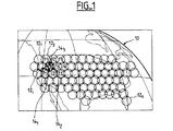
図1は静止衛星に搭載されたアンテナでカバーされる領域10とn個のエリア121、122、...、12nを示す。この例では4つの周波数サブバンドf1、f2、f3、f4が使用されている。
【0005】
エリア12iは、いくつかのサブエリア、141、142などに分割される。各サブエリアは、アンテナの一つの放射要素に対応する。図1は、ある放射要素、例えばエリア12iの中心の放射要素143は、ただ一つの周波数サブバンドf4に対応するのに対して、例えばエリア12i周辺の放射要素のような他の放射要素は、複数のサブバンドすなわち隣接エリアに割り当てられたサブバンドに連結されていることを示す。
【0006】
図2は、前述の種類の通信システムための従来技術による受信アンテナを示す。
【0007】
アンテナは反射器20と反射器の焦点面の近くに複数の放射要素221、...、22Nを備える。各放射要素、例えば放射要素22Nが受信する信号は、特に(高電力)送信周波数を消去することを意図して、最初にフィルタ24Nを通過させ、次いで低雑音増幅器26Nを通過させられる。低雑音増幅器26Nの出力における信号は、分波器30Nでいくつかのパートに分割されて、場合によっては各パートごとに違う係数がつけられる。このように分波することの目的は、1つの放射要素で複数のビームの形成に寄与できるようにすることである。したがって、分波器30Nの出力321はエリア34pに割り当てられ、スプリッタ30Nの別の出力32iは別のエリア34Qに割り当てられる。
【0008】
エリアを画定するための分波器301、...、30Nおよび加算器34p、...、34qは、ビームまたはペンシルビーム形成ネットワークと呼ばれる装置40の部分である。
【0009】
図2のビーム形成ネットワーク40には、各分割器30iの各出力について、移相器42と減衰器44が組み合わせられている。移相器42と減衰器44は、衛星が望まない変位を生じたときの修正のため、または地上のエリア分布を変更するために、放射ダイアグラムを変更する。
【0010】
また、各低雑音増幅器26Nには、故障時に代用するために、同じ型の増幅器26’が連結されている。この目的で、2つのスイッチ46N、48Nを設けて、そのような代用ができるようにしている。したがって、故障を検出する遠隔計測手段(図示せず)と交換を実行するための遠隔制御手段(図示せず)を備える必要がある。
【0011】
【発明が解決しようとする課題】
図2に示したタイプのアンテナシステムには、多数の低雑音増幅器、移相器、減衰器が含まれる。構成要素が多数になることは、その重量ゆえに衛星にとっては問題である。また、多数の移相器42と減衰器44は、信頼性の問題を提起する。
【0012】
本発明は、低雑音増幅器、移相器、減衰器の数を大幅に低減する。
【0013】
【課題を解決するための手段】
この目的で、本発明による受信アンテナは、
マトリックスの各入力が1つの放射要素からの信号を受信し、各出力が1つの移相器と直列に、好ましくは減衰器とも直列に低雑音増幅器に連結されている、少なくとも1つの第1バトラー(Butler)マトリックスと、
第1のバトラーマトリックスの逆行列であって、第1バトラーマトリックスの出力数と同数の入力を有し、かつ第1バトラーマトリックスの入力数と同数の出力を有し、出力がエリアビームを形成するために組み合わされている、第2バトラーマトリックスと、
移相器を制御するための制御手段と、適用可能なところでは、ビームを修正または変更するための減衰器を含む。
【0014】
3dBカプラからなるバトラーマトリックスでは、各出力の信号は、すべての入力信号の組み合わせであるが、様々な入力からの信号は、各入力ごとに異なる特有の位相を有しており、したがって入力信号は、逆バトラーマトリックスを通過し、次いで増幅、移相、適用可能な場合は減衰の処理の後で、一体的に再構成できる。
【0015】
第1バトラーマトリックスの出力数は、入力数に等しいことが好ましい。この場合には、低雑音増幅器の数は放射要素の数と等しくなるが、従来技術では、図2に示すように、低雑音増幅器の数は放射要素の数の2倍である。さらに、移相器の数も放射要素の数に等しいのに対して、従来技術では、放射要素の出力信号が分波され、ビーム形成ネットワークチャネルのそれぞれに移相処理と減衰処理42、44が適用されるために、移相器と減衰器の数は大幅に大きい。
【0016】
移相器を低雑音増幅器と直列に制御して、ビームの修正と変更を行うことは、本発明による受信アンテナでは、特に簡単である。
【0017】
バトラーマトリックスを用いているために、1つの低雑音増幅器が故障すると、すべての出力で信号が均一に減少する。
【0018】
増幅器が故障したときの出力信号に与える影響を緩和するために、一実施形態では、第1バトラーマトリックスの各出力に連結した低雑音増幅器には、複数の(例えば1対の)増幅器を並列に、例えばカプラによって相互接続して設ける。この場合には、増幅器対の1つだけが故障することによる劣化は、単一の増幅器が各出力に連結されている場合の劣化の半分またはそれより少なくなる。
【0019】
8次のバトラーマトリックスを、その各出力に1対の増幅器を並列に連結して用いると、劣化は−0.56dBに等しいことを示すことができる。16次バトラーマトリックスを、第1バトラーマトリックスの各出力に1対の増幅器を連結させる場合には、劣化は−0.28dBとなる。
【0020】
一実施形態では、連結された複数の2次元マトリックス、例えば異なる面にあるマトリックスを用いることにより、各2次元マトリックスの次数をnとすると、放射要素から受信された各信号はn×n個の低雑音増幅器に分配されるようになる。1例としてn=8とすると、この場合には1つの放射要素が受信するそれぞれの信号は、64の低雑音増幅器に分配される。この例では、ただ1つの増幅器が各出力に連結されているとすると、1つの増幅器の故障がもたらす損失は、わずか−0.14dBである。
【0021】
本発明は、同様の構造を有する送信アンテナにも同等に適合する。この場合には、第1バトラーマトリックスの入力は送信すべき信号を受信し、第2バトラーマトリックスの出力は放射要素に接続される。もちろん、送信アンテナには、低雑音増幅器の代わりに電力増幅器を用いる。
【0022】
送信および受信に適合する一実施形態では、バトラーマトリックスの1つとビーム形成ネットワークが単一のデバイスを構成する。
【0023】
送信パワーをすべてのパワー増幅器に分配するために送信アンテナに2つのバトラーマトリックスを有する構造を使うことは、すでに従来技術において知られているが、これらの従来技術のアンテナでは、ビームは図2を参照して受信アンテナについて説明した方法で修正または再構成される。したがって、送信アンテナについては、本発明は移相器の数と、適用可能な場合は、減衰器の数を低減するとともに、これらの制御を簡単にする。さらに、受信アンテナについては、前述したように、本発明は低雑音増幅器の数を低減する(従来技術の受信アンテナと比較して)。
【0024】
1対のバトラーマトリックスはそれぞれ、数エリアに対応するのが好ましい。すべてのエリアに単一のバトラーマトリックスを提供することも可能ではある。しかし、製造を簡単にするには、複数のバトラーマトリックスを用いるのが好ましい。この場合には、いくつかの放射要素を2つの異なるバトラーマトリックスに割り当てることができる。この場合、バトラーマトリックス対の一方に連結された増幅器が故障すると、対応するバトラーマトリックスに連結されたすべてのビームの信号が劣化する。これに反して、同じバトラーマトリックス対について増幅器が故障しない場合には、第2マトリックス対のサブエリアについては減衰がないが、第1マトリックス対に対応するサブエリアは減衰を受けることになる。
【0025】
この欠点を改善する目的で、発明の一実施形態では、送信および受信パワーを均質化するために、少なくとも1つの増幅器が故障したマトリックスに隣接するバトラーマトリックスに連結されている減衰器を制御する。
【0026】
したがって、本発明は、いくつかのエリアに分割された領域をカバーする通信システム用の静止衛星搭載の受信(または送信)アンテナであって、各エリアのためのビームを、反射器の焦点面の近くに配置された複数の放射要素またはリソースで画定し、エリアの位置を変更したり、指向誤りを修正したりするように適合化されているアンテナに関する。
【0027】
アンテナの特徴は、少なくとも1つの第1バトラーマトリックスを含み、マトリックスの各入力(または出力)が1つの放射要素に接続されており、かつマトリックスの各出力(または入力)が増幅器と移相器を介して逆バトラーマトリックスの対応する入力に接続されていること、逆バトラーマトリックスの出力(または入力)がビーム形成ネットワークに連結し、さらにエリアを転位させたり、指向誤りを修正するために移相器を制御するとともに、第1マトリックスと逆バトラーマトリックスが、各放射要素から受信したエネルギーをすべての増幅器に分配し、1つの増幅器の故障がすべての出力信号に均一に分布するようにすることである。
【0028】
各増幅器および各移相器と直列に、増幅器の利得を等化するための減衰器を備えることが好ましい。
【0029】
一実施形態では、アンテナが、入力(または出力)が放射要素に接続された少なくとも2つのバトラーマトリックスを含むとともに、少なくとも1つの放射要素を、第1バトラーマトリックスの入力の1つと第2バトラーマトリックスの入力の1つに接続する。
【0030】
この場合は、2つのバトラーマトリックスに連結された放射要素は、3dBカプラを介して2つのマトリックスの入力(または出力)に接続されるとともに、対応する逆バトラ−マトリックスの出力(または入力)に1つのアナログカプラを設けるのが好ましい。
【0031】
各増幅器と移相器と直列に1つの減衰器を設けることもできる。この場合は、マトリックスに対応する1つの増幅器が故障すれば、2つのマトリックスの出力信号を均質化するために、減衰器が他のバトラーマトリックスの出力信号を減衰させる。
【0032】
一実施形態では、第1バトラーマトリックスの各出力(または入力)と逆バトラーマトリックスの対応する各入力(または出力)との間に、増幅器を並列に設け、例えば90°カプラで連結される。
【0033】
角度誤差を修正するとともに、すべてのビームを同時に指向しなおすために、移相器は、第1バトラーマトリックスの出力信号の位相前面の勾配を変更するのが好ましい。
【0034】
逆バトラーマトリックスとビーム形成ネットワークは、単一のシステムを構成するのが有利である。
【0035】
減衰器が各増幅器と直列に設けられるときは、増幅器は3dB未満のダイナミックレンジを有することが好ましい。
【0036】
バトラーマトリックスは、例えば8次または16次のマトリックスである。
【0037】
一実施形態では、アンテナは、平行な面内に配置された第1バトラーマトリックスの第1のシリーズと、第1シリーズとは異なる方向、例えばそれに直交する別の平行な面内に配置された第1バトラーマトリックスの第2のシリーズを含むことにより、2つの異なる方向において、したがってアンテナによってカバーされるエリアのすべての方向において、エリアの変位、または指向誤りの修正を可能にする。
【0038】
本発明のその他の特徴と利点は、添付の図面を参照して示した、以下の発明の実施形態から明らかになるであろう。
【0039】
【発明の実施の形態】
図2に示すアンテナのように、図3に示す受信アンテナは、1つの反射器(図3に示さず)と反射器の焦点エリア付近に配置された複数の放射要素221、...、22Nを備える。
【0040】
図3の例では、受信アンテナは複数のバトラーマトリックス501、...、50j、...、50pを備える。マトリックスはすべて同一であり、同数の入力と出力を有する。
【0041】
各入力は1つの放射要素から信号を受け取る。したがってバトラーマトリックス50jには、521から528まで8つの入力があり、入力521は放射要素22k+1から信号を受信する。入力528は、放射要素22k+8から信号を受信する。一実施形態では、放射要素22k+1から22k+8は、1つのエリアすなわち1つのビームに割り当てられる。しかし、前述したように、これらの放射要素のいくつかは、隣接するエリアでの他のビームの形成にも関わっている。
【0042】
バトラ−マトリックス50jの各出力は、フィルタと低雑音増幅器を介して逆バトラーマトリックス54iの対応する入力に接続されている。図3は、マトリックス50jの第1出力56k+1とマトリックス50jの最後の出力56k+ 8に対応する低雑音増幅器とフィルタのみを示している。したがって、マトリックス50jの出力56k+1は、フィルタ60k+1と低雑音増幅器62k+1とを直列に経由して、マトリックス54jの入力58k+1に接続されている。フィルタ60k+1の機能は、送信信号を消去することである。フィルタは、特にマトリックスが導波路技術で実装された場合には、マトリックス50jの一部になることもある。
【0043】
バトラーマトリックス54jの伝達関数はマトリックス50jの伝達関数の逆関数である。マトリックス54jは、マトリックス50jの出力数に等しい入力数を有し、マトリック50jの入力数に等しい出力数を有する。
【0044】
様々な逆バトラーマトリックス54jの出力は、ビーム形成ネットワーク66を介してビーム641、...、64sの出力に接続されている。
【0045】
バトラーマトリックスは、後に説明するように、3dBカプラからなり、入力に入った信号は、Mを出力の数とすると、1出力ごとに2π/Mだけ位相をずらせて、すべての出力に分配される。マトリック54jが、マトリックス50jの逆関数を有するので、マトリックス50jの特定の入力からの信号は、フィルタリングおよび増幅を行った後、マトリックス54jの対応する出力で、見い出すことができる。
【0046】
マトリックス50jの各出力56は、同じマトリックスのすべての入力信号を表す信号を配信する。この場合には、低雑音増幅器62の1つまたは複数が故障すると、対応するエリアについてビームの均質性の欠陥をもたらすことはないが、そのかわり放射要素22k+1から22k+8に対応するすべてのエリアの均質な電力低減をもたらす。
【0047】
1つの増幅器が故障すると、マトリックス54jのすべての出力における信号が、20log(1−1/M)dBだけ減少することを示すことができる。但し、ここでMはバトラーマトリックスの次数、つまりこの例ではM=8である。しかし、マトリックス54jの負荷の損失は無視できるので、アンテナのG/Tパラメータの劣化は、この値の半分、すなわち101og(1−1/M)となる。この理由は、支配的なノイズが低雑音増幅器の出力で拾われたノイズであり、故障した増幅器は、ノイズの原因となることはなくなり、全ノイズパワーがファクタ(1−1/M)だけ低減されるためである。
【0048】
このような条件下では(8次のマトリックスについては)、1つの低雑音増幅器が故障すると、G/T比の劣化は−0.56dB、またはM=6の場合の劣化は−0.28dBとなる。前記の数字は、図5を参照して以下に説明するように、各増幅器が1対の増幅器からなり、「増幅器の故障」という表現が1対の増幅器の1つだけを指すという仮説に対応するものである。
【0049】
1つの低雑音増幅器が故障すると、出力信号間の分離も劣化する。したがって、故障前に入力信号が完全に分離されている、そして出力信号も完全に分離されている場合には、1つの増幅器の故障後は、2つの出力間の分離は20log(M−1)dB、すなわちG=8ならば17dB、G=16ならば23.5dBとなる。
【0050】
前記の値は、従来手法の計算を用いて得た理論値である。しかし、適切な技術、例えばコンパクトな導波路分配器を用いれば、損失および誤りは低く、実際に得られる結果は計算に一致する。
【0051】
一実施形態では、逆マトリックス54jとビーム形成ネットワーク66が単一の多層回路を構成する。これが可能なのは、逆マトリックスとネットワーク66は同じ技術を用いたプレーナ多層回路で構築するのが好ましく、したがって同一パッケージにできるからである。低雑音増幅器より下流の回路に起因する損失は、上流で生じた損失よりも重要性は低く、導波路回路のかわりにマイクロストリップまたはトリプレート回路を使用することができる。マイクロストリップおよびトリプレート回路はより小型であるが、導波路回路よりもわずかに大きい損失がある。しかし、これは前述のように重要な問題ではない。
【0052】
図4は、バトラーマトリックスを用いてビームの修正または変更の制御を簡単化した本発明の第3の実施形態を示す。図では、アンテナに対して正常な放射方向70を鎖線で、例えば衛星の不安定性が原因でアンテナから見て誤った発射方向72を破線で示してある。
【0053】
放射方向70におけるエネルギーは実線図74に対応し、放射方向72のエネルギーが破線図76に対応する。したがって、アンテナの方向が正しくないと、焦点面の放射をシフトさせ、所与の方向から最大のエネルギーを取り込むことを狙いとする放射要素は、強く減衰されたエネルギーを受信する。したがって、このシフトによって、ゲインは大幅に減少し、分離が低化する。
【0054】
図2を参照して示したアンテナの再指向、すなわちその方向の修正のために、従来技術の解決策では、各放射要素に移相器42と減衰器44を割り当て、移相器42を個々に制御する。また、減衰器が高いダイナミックレンジを有するのは、いくつかのソースを「切」にしたり「入」にしたりできなくてはならないためである。この制約が理由で、低雑音増幅器の利得は高くなくてはならない。また、1つのエリアに割り当てられた放射要素(ソース)の数は、サブエリアの数よりも大きくなくてはならない。例えば、7つの放射要素が公称ダイアグラムを構成すると、再指向を可能にするのにこれらの放射要素で形成されるセプテット(7個組)のまわりに少なくとも1つのリングが必要となる。したがって、1つのエリアへのアクセスごとに19のソース(7つではなく)を備える必要がある。エリアが正方メッシュを形成し、かつ各エリアについて4つのアクティブソースが備えられると、1つのエリアに対するアクセス数は16となる。
【0055】
図2に示した解決方法と比較して、本発明は指向の修正と、地上のエリアの変位を簡略化する。本発明はバトラーマトリックス50jがあることを活用する。出発点は、マトリックス50jの出力において、位相前面80k+1は、簡単に所望の位相前面82k+1に傾けることが出来るという事実である。これは、各ビームの信号が、対応するマトリックス50jのすべての出力にわたって、所与の位相勾配で配分されているためである。各入力に対応する勾配は、ある固定値、すなわち与えられた次数のマトリックスによって決まる定数によって分離される。この場合には、再指向、すなわち要求された修正を成し遂げるには、マトリックス50jの各出力対応に1つの移相器を備えて、勾配を伸ばすだけで十分である。
【0056】
図4において、直線セグメント80k+1と82k+1は、放射要素22k+1からの信号に対する出力56k+1から56k+8までの位相の分布を表している。直線セグメント80k+3および82k+3は、放射要素22k+3からの信号に対する出力の位相の分布に対応しており、直線セグメント80k+7および82k+7は放射要素22k+7によって供給される信号に対するすべての出力についての位相と対応している。これらの図では、慣例によって、出力56k+1と、直線セグメント82k+1と出力56k+1につながる直線セグメントDk+1との交点Pk+1との間の距離が、放射要素22k+1からくる信号の出力の位相を表している。同様に、直線セグメント82k+1と対応する直線セグメントDk+2他との交点は、やはり放射要素22k+1に対応する信号についての出力における信号の位相を表す。
【0057】
したがって、出力56k+1について、例えば、放射要素22iからくる信号の位相前面を、80から82まで修正するためには、位相修正dk+1、dk+2、...、dk+8を適用する必要がある。しかし、dk+1、dk+2、dk+3などの値は同一であることがわかる。したがって、共通の値dk+1、dk+2などを修正するのには、単一の移相器84k+1で十分である。
【0058】
バトラーマトリックス50jによってもたらされる修正は、図中に示した単一の面においてのみ有効である。実際の修正をもたらすためには、バトラーマトリックスは、別の面、例えば図6で示し、以下で説明予定の直角の面にも備えなくてはならない。
【0059】
本実施例では、この種の移相器84は、低雑音増幅器52の下流に設けられる。したがって、図4の移相器84k+1は、減衰器86k+1を介して増幅器62k+1の出力に接続されており、移相器84k+1の出力は逆マトリックス54jの対応する入力に接続されている。
【0060】
この実施形態では、可変減衰器86を用いて増幅器62の利得を等化する。これらの減衰器は、後に説明するように、マトリックス50jに結合されたマトリックスに接続されている1つまたは複数の低雑音増幅器が故障したときの補償を提供する。
【0061】
この実施例においては、送信周波数が受信周波数と干渉するのを防ぐために、バトラーマトリックス50j中に高域通過フィルタを設ける。このフィルタは、例えばカットオフ周波数が受信バンドと送信バンドの間にある導波路である。
【0062】
この実施例では、図3を参照して述べたように、逆バトラーマトリックス54jを、ビーム形成ネットワーク66に統合することも可能である。
【0063】
図5に示す変形形態では、低雑音増幅器62は90°カプラを用いて連結して1対にする。より正確には、増幅器62k+1が増幅器62k+2と連結されて、90°カプラ88が増幅器の入力同士を接続し、別の90°カプラが増幅器の出力を相互接続する。したがって、1つの増幅器が故障したときには、8次のバトラーマトリックスを用いると損失は0.28dBであり、これは図5に示す特徴には含まれていないが、バトラーマトリックスが16次マトリックスである場合と同じ損失である。この理由は、バトラーマトリックスの出力と連結する各増幅器2つを1対にして実装することで、増幅器対の1方が故障したとき、他方の増幅器がまだ作動しているために、パワー損失は半分になるためである。言い換えると、これはバトラーマトリックスの次数を倍にするのと同じ効果がある。
【0064】
より一般的には、やはり増幅器の故障の影響を低減する目的において、それぞれの出力を複数の増幅器と並列に連結してもよい。この場合、再組み合わせを伴う分波を容易にするために、各出力に対応する増幅器の数は2の累乗となる。
【0065】
これまで記述した実施例においては、複数のマトリックス50jを用いたが、単一のM次のバトラーマトリックスを備えることも可能であり、この場合Mは放射要素の数である。しかし、衛星に搭載するためのスペースの制約から、放射要素の数が多いときには、この種のバトラーマトリックスを単一面に搭載することが出来ない。この場合、図6に示すような、2次元配置のバトラーマトリックスを用いる必要があり、このマトリックスは、第1レイヤが8つのバトラーマトリックス901から908からなり、第2レイヤがマトリックス90と直交配置されたバトラーマトリックス921から928からなる、64次のマトリックスである。
【0066】
この種の2次元マトリックスの実装は複雑であり、またこのマトリックスはアンテナの雑音温度を含む損失を発生する可能性がある。しかし、この種の2次元マトリックスは、2つの直交面において同時に再指向することが可能であり、より多数の低雑音増幅器を相互接続することで故障の影響を軽減することができる。
【0067】
一般的に、2つの異なる面において修正を行うことができるためには、マトリックス90と92が、2つの直交する面にあることは絶対条件ではない。2つの面が十分離れて異なる方向にあるだけで十分である。1つの例では、隣接するソースの中心が正3角形を形成する配列への接続を容易に行うために、方向が60°ずれている。
【0068】
8次および16次のバトラーマトリックスは4次のバトラーマトリックスから構築される。
【0069】
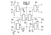
図7は4次のバトラーマトリックスを示し、これには2つの入力カプラ94、96、および2つの出力カプラ102、104、および2つの中間カプラ98、100を有する、6つの3dBカプラが含まれる。ここで示さない変形形態では、中間カプラ98と100の代わりに、クロスオーバが用いられるが、クロスオーバは導波路技術では実装が困難である。
【0070】
3dBカプラ、例えば入力カプラ104は、2つの入力1041と1042、および2つの出力1043と1044を有する。1つの入力に適用される信号、例えば入力番号1041のパワーは、2つの出力1043、1044に分配され、この2つの出力信号間にπ/2の位相シフトを生じる。したがって、図7に示すように、入力1041の信号Sが、出力1043で信号S/√2となり、出力1044で信号−jS/√2となる。入力1042のシグナルS’は、出力1044の信号S’/√2と出力1043での信号−jS/√2に対応する。
【0071】
入力1041での信号は、4次バトラーマトリックスの4つの出力、すなわちカプラ94と96のそれぞれの出力943、944、および963、964で取得される。信号jS/2は出力943で取得され、信号−S/2は出力944で、信号−jSe−jψ/2は出力963で、信号Se−jψ/2は出力964で取得される。カプラ98と100の間には、移相器105によって一定位相fが導入される。移相器は、中心チャネルと外側チャネルのガイド長の差を補償するように設定される。したがって、マトリックスは、出力における信号の位相を、正規の勾配にする。
【0072】
4次のバトラーマトリックスでは、出力信号の位相は、増分90°で変化する。8次のバトラーマトリックスでは、増分は45°である。
【0073】
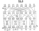
8次のバトラーマトリックス120または130(図8)は、2つの4次のマトリックス122および124から構築され、2つの4次マトリックスの出力は、4つの3dBカプラ1261、1262、1263、1264によって組み合わせられる。
【0074】
16次のバトラーマトリックス(図8)は、2つの8次マトリックス120と130から構築され、マトリックス120、130の出力は、8つの3dBカプラ1321から1328によって組み合わせられる。
【0075】
図8に示す16次マトリックスの行のクロスオーバは、図7の4次マトリクスのカプラ98および100と同様の先頭と最後のカプラによって置き換え可能であることを留意されたい。このことは当技術分野で知られている。
【0076】
この実施例では、バトラーマトリックス50は、「小型導波路分配器」の技術を利用する。この場合、フィルタリングをマトリックス中に統合して、低雑音増幅器が帯域外の干渉信号によって非線形化されるのを防ぐことが可能である。これは特に、非常に高い送信パワーのために、近くの受信アンテナに必然的に再入力される送信周波数を排除するためのフィルタリングに関係する。
【0077】
各バトラーマトリックス50jが、1つまたは複数のエリアに対応し、その他のマトリックスは、バトラーマトリックス50jが連結されたエリアでは動作しないことが好ましい。しかし、それぞれのソースが一般に複数の隣接エリアの形成に寄与するために、この条件を満足することはいつも可能とは限らない。この場合、ソース22q(図9)は、2つの隣接マトリックス501、502と連結されなくてはならず、マトリックス501と502のそれぞれの入力1401と1402に3dBカプラ142を介して接続される。同一のカプラ144が、逆マトリックス50’1と50’2の対応する出力を組み合わせる。
【0078】
カプラ142、144もまた、マトリックス501、50’1またはマトリックス502、50’2のどちらかに連結された低雑音増幅器の1つが故障した場合に、2つのマトリックスが共有するソースからくる信号の劣化を制限する。この理由は、そのようなソースに拾い上げられた信号は、2つのマトリックスに等しく分波されるからである。したがって、故障によって影響を受ける部分だけが動作する。
【0079】
これらのカプラは、マトリックス中の故障によって生じる不均衡を低減(半減)するが、故障時に残される不均衡は一般に許容できるものではない。これが、1つのマトリックス、例えばマトリックス番号501に連結された1つの低雑音増幅器が故障した場合に、カプラ142、144の代わりに、またはそれに加えて、図4に示す減衰器86を用いて、もう一方のマトリックス502の出力信号を、マトリックス501と502の出力信号がバランスする量だけ、減衰させることの理由である。この減衰量は、3dBカプラなしの入力または出力に対しては20log(1−1/M)dB、または3dBカプラ144に接続された出力に対しては10log(1−1/M)dBでなくてはならない。
【0080】
減衰処理は、故障が検出された後に自動的に適用される。低雑音増幅器の故障は、例えば低雑音増幅器の下流のダイオード検出器を用いて、その増幅器の電源電流をモニタリングすることによって検出される。
【0081】
この実施例では、減衰器86(図4)のダイナミックレンジは狭く、3dB未満であることを留意されたい。これは、減衰器のダイナミックレンジは原理的に、アンテナを実装した時に、減衰器が様々な低雑音増幅器の利得を等化する機能によって決まるためである。この等化のための、最大のダイナミックレンジは2.5dBである。さらに、隣接するマトリックスの増幅器が故障した時に、マトリックスの出力を再均衡させるのに必要な補償は0.28dBである。
【0082】
これまで受信アンテナにだけついて述べたが、構造が似ているが構成が反対の送信アンテナについても、低雑音増幅器の代わりにパワー増幅器を用いることによって、本発明があてはまることはいうまでもない。
【図面の簡単な説明】
【図1】いくつかのエリアに分割されており、静止衛星に搭載されたアンテナでカバーされるテリトリを示す図である。
【図2】従来技術の受信アンテナを示す図である。
【図3】本発明による受信アンテナの部分を示す構成図である。
【図4】本発明による受信アンテナの部分を示す構成図である。
【図5】本発明によるアンテナの一部の変形形態を示す構成図である。
【図6】64次のバトラーマトリックスを示す図である。
【図7】4次のバトラーマトリックスを示す構成図である。
【図8】16次のバトラーマトリックスを示す構成図である。
【図9】本発明の別の特徴を示す受信アンテナの構成図である。
【符号の説明】
121、122、12n エリア
141、142、14n サブエリア
221、222、22k+N 放射要素
241、242、24n フィルタ
261、262、26n 低雑音増幅器
30N 分波器
40 ビーム形成ネットワーク
44 減衰器
501、50j、50p バトラーマトリックス
54j 逆バトラーマトリックス
60k+1 フィルタ
62k+1 増幅器
84k+1 移相器
86k+1 減衰器
88、90 90°カプラ
142 3dBカプラ
f1、f2、f3、f4 周波数サブバンド[0001]
BACKGROUND OF THE INVENTION
The present invention relates to a communication antenna that is mounted on a geostationary satellite and relays communication to a vast territory.
[0002]
[Prior art]
Geosynchronous satellites equipped with transmit and receive antennas are used to provide communication to a vast territory, for example, an area of North America size, each antenna having multiple radiating elements or sources. It has a connected reflector. In order to allow reuse of communication resources, especially frequency subbands, the coverage area is divided into several areas, resources are assigned to different areas, and resources in one area are assigned, Different resources are allocated to adjacent areas.
[0003]
Each area has a diameter on the order of, for example, several hundred kilometers, in which range each area is covered with a plurality of radiating elements in order to provide high gain and sufficiently homogeneous radiation from the antenna in the area. Must-have.
[0004]
FIG. 1 shows an
[0005]
[0006]
FIG. 2 shows a receiving antenna according to the prior art for a communication system of the kind described above.
[0007]
The antenna includes a plurality of radiating elements 22 near the
[0008]
A
[0009]
The
[0010]
Each low noise amplifier 26NAre connected to the same type of amplifier 26 'for substitution in the event of a failure. For this purpose, the two switches 46N48NTo make such a substitution. Therefore, it is necessary to provide a remote measuring means (not shown) for detecting a failure and a remote control means (not shown) for executing the replacement.
[0011]
[Problems to be solved by the invention]
The antenna system of the type shown in FIG. 2 includes a number of low noise amplifiers, phase shifters, and attenuators. The large number of components is a problem for the satellite because of its weight. Also, the large number of
[0012]
The present invention significantly reduces the number of low noise amplifiers, phase shifters and attenuators.
[0013]
[Means for Solving the Problems]
For this purpose, the receiving antenna according to the invention is
At least one first butler wherein each input of the matrix receives a signal from one radiating element and each output is connected in series with a phase shifter, preferably in series with an attenuator, to a low noise amplifier. (Butler) matrix;
An inverse matrix of the first Butler matrix, having the same number of inputs as the number of outputs of the first Butler matrix, and having the same number of outputs as the number of inputs of the first Butler matrix, the outputs forming an area beam A second Butler matrix, combined for
Control means for controlling the phase shifter and, where applicable, an attenuator for modifying or changing the beam.
[0014]
In a Butler matrix consisting of 3 dB couplers, the signal at each output is a combination of all input signals, but the signals from the various inputs have a unique phase that is different for each input, so the input signal is , Pass through the inverse Butler matrix and then after amplification, phase shifting, and if applicable attenuation treatment, can be reconstructed in one piece.
[0015]
The number of outputs of the first Butler matrix is preferably equal to the number of inputs. In this case, the number of low noise amplifiers is equal to the number of radiating elements, but in the prior art, as shown in FIG. 2, the number of low noise amplifiers is twice the number of radiating elements. Furthermore, while the number of phase shifters is also equal to the number of radiating elements, in the prior art, the output signal of the radiating elements is demultiplexed and phase shifting and
[0016]
Controlling the phase shifter in series with the low noise amplifier to modify and change the beam is particularly simple with the receiving antenna according to the invention.
[0017]
Because of the use of a Butler matrix, if one low noise amplifier fails, the signal is reduced uniformly at all outputs.
[0018]
In order to mitigate the impact on the output signal when an amplifier fails, in one embodiment, a low noise amplifier coupled to each output of the first Butler matrix includes multiple (eg, a pair) amplifiers in parallel. For example, they are connected by a coupler. In this case, the degradation due to failure of only one of the amplifier pairs is half or less of the degradation when a single amplifier is coupled to each output.
[0019]
Using an 8th order Butler matrix with a pair of amplifiers connected in parallel at each output, it can be shown that the degradation is equal to -0.56 dB. When a 16th order Butler matrix is connected to a pair of amplifiers at each output of the first Butler matrix, the degradation is -0.28 dB.
[0020]
In one embodiment, by using a plurality of concatenated two-dimensional matrices, eg, matrices on different planes, where each two-dimensional matrix is of order n, each signal received from the radiating element is n × n It will be distributed to the low noise amplifier. As an example, if n = 8, then each signal received by one radiating element is distributed to 64 low noise amplifiers. In this example, if only one amplifier is coupled to each output, the loss caused by one amplifier failure is only -0.14 dB.
[0021]
The present invention is equally suitable for transmitting antennas having a similar structure. In this case, the input of the first Butler matrix receives the signal to be transmitted and the output of the second Butler matrix is connected to the radiating element. Of course, a power amplifier is used for the transmitting antenna instead of the low noise amplifier.
[0022]
In one embodiment adapted for transmission and reception, one of the Butler matrices and the beam forming network constitute a single device.
[0023]
It is already known in the prior art to use a structure with two Butler matrices in the transmit antenna to distribute the transmit power to all power amplifiers, but in these prior art antennas the beam is shown in FIG. Modified or reconfigured in the manner described with reference to the receiving antenna. Thus, for transmit antennas, the present invention reduces the number of phase shifters and, where applicable, the number of attenuators and simplifies their control. Furthermore, for receive antennas, as described above, the present invention reduces the number of low noise amplifiers (as compared to prior art receive antennas).
[0024]
Each pair of Butler matrices preferably corresponds to several areas. It is also possible to provide a single Butler matrix for all areas. However, it is preferred to use a plurality of Butler matrices to simplify manufacturing. In this case, several radiating elements can be assigned to two different Butler matrices. In this case, if an amplifier connected to one of the Butler matrix pairs fails, the signals of all the beams connected to the corresponding Butler matrix are degraded. On the other hand, if the amplifier does not fail for the same Butler matrix pair, there will be no attenuation for the subarea of the second matrix pair, but the subarea corresponding to the first matrix pair will be attenuated.
[0025]
In order to remedy this drawback, in one embodiment of the invention, at least one amplifier controls an attenuator coupled to a Butler matrix adjacent to the failed matrix in order to homogenize transmit and receive power.
[0026]
Accordingly, the present invention is a receive (or transmit) antenna mounted on a geostationary satellite for a communication system that covers an area divided into several areas, with the beam for each area in the focal plane of the reflector. The invention relates to an antenna that is defined by a plurality of nearby radiating elements or resources and that is adapted to change the position of an area or correct a pointing error.
[0027]
The antenna features include at least one first Butler matrix, each input (or output) of the matrix is connected to one radiating element, and each output (or input) of the matrix includes an amplifier and a phase shifter. Connected to the corresponding input of the inverse Butler matrix, the output (or input) of the inverse Butler matrix is connected to the beamforming network, and the phase shifter further shifts the area and corrects the pointing error The first matrix and the inverse Butler matrix distribute the energy received from each radiating element to all amplifiers so that one amplifier failure is evenly distributed across all output signals. .
[0028]
Preferably, an attenuator for equalizing the gain of the amplifier is provided in series with each amplifier and each phase shifter.
[0029]
In one embodiment, the antenna includes at least two Butler matrices whose inputs (or outputs) are connected to the radiating elements, and the at least one radiating element includes one of the inputs of the first Butler matrix and the second Butler matrix. Connect to one of the inputs.
[0030]
In this case, a radiating element coupled to two Butler matrices is connected to the inputs (or outputs) of the two matrices via a 3 dB coupler and 1 to the corresponding inverse Butler-matrix outputs (or inputs). Two analog couplers are preferably provided.
[0031]
One attenuator can be provided in series with each amplifier and phase shifter. In this case, if one amplifier corresponding to the matrix fails, the attenuator attenuates the output signals of the other Butler matrices in order to homogenize the output signals of the two matrices.
[0032]
In one embodiment, an amplifier is provided in parallel between each output (or input) of the first Butler matrix and each corresponding input (or output) of the inverse Butler matrix, for example connected by a 90 ° coupler.
[0033]
In order to correct the angular error and redirect all beams simultaneously, the phase shifter preferably changes the slope of the phase front of the output signal of the first Butler matrix.
[0034]
The inverse Butler matrix and the beam forming network advantageously constitute a single system.
[0035]
When an attenuator is provided in series with each amplifier, the amplifier preferably has a dynamic range of less than 3 dB.
[0036]
The Butler matrix is, for example, an 8th order or 16th order matrix.
[0037]
In one embodiment, the antenna is arranged in a first series of first Butler matrices arranged in parallel planes and in a different direction from the first series, for example in another parallel plane orthogonal thereto. Including a second series of 1 Butler matrices allows area displacement, or correction of pointing errors, in two different directions and thus in all directions of the area covered by the antenna.
[0038]
Other features and advantages of the present invention will become apparent from the following embodiments of the invention, illustrated with reference to the accompanying drawings.
[0039]
DETAILED DESCRIPTION OF THE INVENTION
Like the antenna shown in FIG. 2, the receiving antenna shown in FIG. 3 has a reflector (not shown in FIG. 3) and a plurality of radiating elements 22 arranged near the focal area of the reflector.1,. . . , 22NIs provided.
[0040]
In the example of FIG. 3, the receiving antenna has a plurality of Butler matrices 50.1,. . . , 50j,. . . , 50pIs provided. All matrices are identical and have the same number of inputs and outputs.
[0041]
Each input receives a signal from one radiating element. Therefore, the
[0042]
[0043]
Butler Matrix 54jThe transfer function is
[0044]
Various Inverse Butler Matrix 54jOutput of beam 64 through beam forming network 66.1,. . . , 64sConnected to the output.
[0045]
As described later, the Butler matrix is composed of a 3 dB coupler, and the input signal is distributed to all outputs by shifting the phase by 2π / M for each output, where M is the number of outputs. . Matric 54jBut the
[0046]
[0047]
If one amplifier fails, the matrix 54jCan be shown to decrease by 20 log (1-1 / M) dB. Here, M is the order of the Butler matrix, that is, M = 8 in this example. However, the matrix 54jIs negligible, the degradation of the antenna G / T parameter is half this value, ie 101 og (1-1 / M). This is because the dominant noise is the noise picked up at the output of the low noise amplifier, the failed amplifier will not cause noise, and the total noise power is reduced by a factor (1-1 / M). It is to be done.
[0048]
Under these conditions (for the 8th order matrix), if one low noise amplifier fails, the degradation of the G / T ratio is -0.56 dB, or the degradation for M = 6 is -0.28 dB. Become. The numbers correspond to the hypothesis that each amplifier consists of a pair of amplifiers and the expression “amplifier failure” refers to only one of the pair of amplifiers, as described below with reference to FIG. To do.
[0049]
If one low noise amplifier fails, the separation between the output signals is also degraded. Thus, if the input signal is completely separated before the failure and the output signal is also completely separated, after one amplifier failure, the separation between the two outputs is 20 log (M-1). dB, that is 17 dB if G = 8, and 23.5 dB if G = 16.
[0050]
The above-mentioned values are theoretical values obtained using the calculation of the conventional method. However, with appropriate techniques, such as a compact waveguide distributor, the loss and error are low and the actual results are consistent with the calculations.
[0051]
In one embodiment, the inverse matrix 54jAnd the
[0052]
FIG. 4 shows a third embodiment of the present invention using a Butler matrix to simplify beam modification or change control. In the figure, a
[0053]
The energy in the
[0054]
In order to redirect the antenna, that is, to correct its direction as shown with reference to FIG. 2, in the prior art solution, each radiating element is assigned a
[0055]
Compared to the solution shown in FIG. 2, the present invention simplifies orientation correction and displacement of the ground area. The present invention is a Butler matrix 50.jTake advantage of that. Starting point is
[0056]
In FIG.k + 1And 82k + 1The radiating element 22k + 1Output 56 for signal fromk + 1From56k + 8The distribution of the phase up to is shown. Straight line segment 80k + 3And 82k + 3The radiating element 22k + 3Corresponds to the phase distribution of the output with respect to the signal fromk + 7And 82k + 7Is the radiating element 22k + 7Corresponds to the phase for all outputs for the signal supplied by. In these figures, by convention, the output 56k + 1And straight segment 82k + 1And output 56k + 1Straight line segment D leading tok + 1Intersection P withk + 1The distance between and the radiating element 22k + 1It represents the output phase of the signal coming from. Similarly, straight line segment 82k + 1Line segment D corresponding tok + 2The intersection with the other is also the radiating element 22k + 1Represents the phase of the signal at the output for the signal corresponding to.
[0057]
Therefore, output 56k + 1For example, the radiating element 22iTo correct the phase front of the signal coming from 80 to 82, the phase correction dk + 1, Dk + 2,. . . , Dk + 8Need to apply. But dk + 1, Dk + 2, Dk + 3It can be seen that the values such as are the same. Therefore, the common value dk + 1, Dk + 2To correct the single phase shifter 84k + 1Is enough.
[0058]
[0059]
In this embodiment, this type of phase shifter 84 is provided downstream of the low noise amplifier 52. Therefore, the phase shifter 84 of FIG.k + 1Attenuator 86k + 1Through the amplifier 62k + 1Is connected to the output of the phase shifter 84.k + 1Is the inverse matrix 54jConnected to the corresponding input.
[0060]
In this embodiment, a variable attenuator 86 is used to equalize the gain of the amplifier 62. These attenuators are arranged in a
[0061]
In this embodiment, the
[0062]
In this embodiment, as described with reference to FIG.jCan also be integrated into the
[0063]
In the variation shown in FIG. 5, the low noise amplifiers 62 are coupled together using a 90 ° coupler. More precisely, the amplifier 62k + 1Amplifier 62k + 2And a 90 °
[0064]
More generally, each output may be connected in parallel with a plurality of amplifiers, again for the purpose of reducing the effects of amplifier failures. In this case, the number of amplifiers corresponding to each output is a power of 2 to facilitate demultiplexing with recombination.
[0065]
In the embodiments described so far, a plurality of
[0066]
The implementation of this type of two-dimensional matrix is complex and this matrix can generate losses including antenna noise temperature. However, this type of two-dimensional matrix can be redirected simultaneously in two orthogonal planes, and the effect of failure can be reduced by interconnecting a larger number of low noise amplifiers.
[0067]
In general, it is not an absolute requirement that the
[0068]
The 8th and 16th order Butler matrices are constructed from the 4th order Butler matrix.
[0069]
FIG. 7 shows a fourth-order Butler matrix, which includes six 3 dB couplers with two
[0070]
A 3 dB coupler, eg,
[0071]
Input 1041At 4 outputs of the fourth order Butler matrix, ie, the outputs 94 of the
[0072]
In a 4th order Butler matrix, the phase of the output signal changes in increments of 90 °. For an 8th order Butler matrix, the increment is 45 °.
[0073]
The 8th
[0074]
The 16th order Butler matrix (FIG. 8) is constructed from two
[0075]
It should be noted that the 16th order matrix row crossover shown in FIG. 8 can be replaced by a first and last coupler similar to the fourth
[0076]
In this embodiment, the
[0077]
Each
[0078]
[0079]
These couplers reduce (halve) the imbalance caused by faults in the matrix, but the imbalance left in the event of a fault is generally not acceptable. This is a matrix,
[0080]
The attenuation process is automatically applied after a fault is detected. The failure of the low noise amplifier is detected by monitoring the power supply current of the amplifier, for example using a diode detector downstream of the low noise amplifier.
[0081]
Note that in this example, the dynamic range of attenuator 86 (FIG. 4) is narrow and less than 3 dB. This is because the dynamic range of the attenuator is in principle determined by the function of the attenuator equalizing the gains of various low noise amplifiers when the antenna is mounted. The maximum dynamic range for this equalization is 2.5 dB. Furthermore, the compensation required to rebalance the matrix output when an adjacent matrix amplifier fails is 0.28 dB.
[0082]
Although only the receiving antenna has been described so far, it goes without saying that the present invention can be applied to a transmitting antenna having a similar structure but the opposite structure by using a power amplifier instead of a low noise amplifier.
[Brief description of the drawings]
FIG. 1 is a diagram showing a territory that is divided into several areas and that is covered by an antenna mounted on a geostationary satellite.
FIG. 2 is a diagram showing a conventional receiving antenna.
FIG. 3 is a block diagram showing a part of a receiving antenna according to the present invention.
FIG. 4 is a block diagram showing a part of a receiving antenna according to the present invention.
FIG. 5 is a block diagram showing a modification of a part of the antenna according to the present invention.
FIG. 6 shows a 64th order Butler matrix.
FIG. 7 is a configuration diagram showing a fourth-order Butler matrix.
FIG. 8 is a block diagram showing a 16th-order Butler matrix.
FIG. 9 is a configuration diagram of a receiving antenna showing another feature of the present invention.
[Explanation of symbols]
121, 122, 12n area
141, 142, 14n Sub-area
221, 222, 22k + N Radiation element
241, 242, 24nfilter
261, 262, 26n Low noise amplifier
30N Duplexer
40 Beam forming network
44 Attenuator
501, 50j,50p Butler Matrix
54j Reverse butler matrix
60k + 1 filter
62k + 1 amplifier
84k + 1 Phase shifter
86k + 1 Attenuator
88, 90 90 ° coupler
142 3dB coupler
f1, f2, f3, f4 frequency subbands
Claims (13)
少なくとも2つのバトラーマトリックス(M1、M2)を含み、前記少なくとも2つのバトラーマトリックス(M 1 、M 2 )は、複数の放射要素に接続された入力(または出力)を有し、少なくとも1つの放射要素(22q)が、第1マトリックス(M1)の入力および第2マトリックス(M2)の入力に接続されている、アンテナ。A receive (or transmit) antenna for a geostationary satellite in a communication system for covering a territory divided into several areas, wherein a beam for each area is arranged in the vicinity of the focal plane of the reflector. Means defined by a radiating element or source and comprising means for changing the position of the area or correcting the pointing error of the antenna, comprising at least one first Butler matrix (50 j ), said matrix Each input (or output) is connected to a radiating element (22 k + 1 ,..., 22 k + 8 ), and each output (or input) is connected to an inverse butler via an amplifier (62 k + 1 ) and a phase shifter (84 k + 1 ) is connected to the corresponding input of the matrix (54 j), the output of the inverse Butler matrix (or input) of the beam-shaped It is connected to the network, or the phase shifter shifting the area, or with modifying the directional error, one of the first matrix or inverse Butler matrix, the energy which each radiating element is received, the amplifier group Distributing, so that the effect of one amplifier failure is evenly distributed to all output signals,
Even without least comprises two Butler matrices (M 1, M 2), wherein at least two Butler matrices (M 1, M 2) has inputs connected to a plurality of radiating elements (or output), at least one radiating element (22 q) is, it is connected to the input of the input and a second matrix of the first matrix (M 1) (M 2) , the antenna.
Applications Claiming Priority (2)
| Application Number | Priority Date | Filing Date | Title |
|---|---|---|---|
| FR0008794A FR2811480B1 (en) | 2000-07-06 | 2000-07-06 | TELECOMMUNICATION ANTENNA INTENDED TO COVER A LARGE GROUND ZONE |
| FR0008794 | 2000-07-06 |
Publications (3)
| Publication Number | Publication Date |
|---|---|
| JP2002111361A JP2002111361A (en) | 2002-04-12 |
| JP2002111361A5 JP2002111361A5 (en) | 2008-08-14 |
| JP5007005B2 true JP5007005B2 (en) | 2012-08-22 |
Family
ID=8852173
Family Applications (1)
| Application Number | Title | Priority Date | Filing Date |
|---|---|---|---|
| JP2001200441A Expired - Lifetime JP5007005B2 (en) | 2000-07-06 | 2001-07-02 | Communication antenna covering a large ground area |
Country Status (7)
| Country | Link |
|---|---|
| US (1) | US6650281B2 (en) |
| EP (1) | EP1170823B1 (en) |
| JP (1) | JP5007005B2 (en) |
| AT (1) | ATE339023T1 (en) |
| CA (1) | CA2351119A1 (en) |
| DE (1) | DE60122832T2 (en) |
| FR (1) | FR2811480B1 (en) |
Families Citing this family (15)
| Publication number | Priority date | Publication date | Assignee | Title |
|---|---|---|---|---|
| FR2826511B1 (en) * | 2001-06-21 | 2003-12-19 | Cit Alcatel | REPINTING METHOD FOR REFLECTOR NETWORK ANTENNA |
| KR100457180B1 (en) * | 2002-08-31 | 2004-11-16 | 한국전자통신연구원 | Apparatus for Coupling Signal in Active Phase Array Antenna System |
| FR2860648B1 (en) | 2003-10-03 | 2006-02-24 | Agence Spatiale Europeenne | MULTI-BEAM COMMUNICATION SATELLITE ANTENNA HAVING FAULT COMPENSATION |
| US7710340B2 (en) * | 2006-01-13 | 2010-05-04 | Lockheed Martin Corporation | Reconfigurable payload using non-focused reflector antenna for HIEO and GEO satellites |
| US8354956B2 (en) | 2006-01-13 | 2013-01-15 | Lockheed Martin Corporation | Space segment payload architecture for mobile satellite services (MSS) systems |
| JP4795096B2 (en) * | 2006-04-25 | 2011-10-19 | 村角工業株式会社 | Medical examination cassette |
| FR2964800B1 (en) * | 2010-09-10 | 2012-08-31 | Centre Nat Etd Spatiales | MULTIFUNCAL TELECOMMUNICATION ANTENNA ON HIGH CAPACITY SATELLITE AND ASSOCIATED TELECOMMUNICATION SYSTEM |
| JP2012222725A (en) * | 2011-04-13 | 2012-11-12 | Toshiba Corp | Active array antenna device |
| US9806428B2 (en) | 2013-06-16 | 2017-10-31 | Siklu Communication ltd. | Systems and methods for forming, directing, and narrowing communication beams |
| US9413078B2 (en) | 2013-06-16 | 2016-08-09 | Siklu Communication ltd. | Millimeter-wave system with beam direction by switching sources |
| US20160036403A1 (en) * | 2014-07-23 | 2016-02-04 | Wilson Electronics, Llc | Multiple-port signal boosters |
| FR3053166B1 (en) * | 2016-06-28 | 2018-06-22 | Centre National D'etudes Spatiales (Cnes) | MULTI-BEAM SOURCE FOR MULTI-BEAM ANTENNA |
| CA3058814A1 (en) | 2017-04-06 | 2018-10-11 | Wilson Electronics, Llc | Techniques for configuring the power or gain of a repeater |
| CN109066102A (en) * | 2018-06-29 | 2018-12-21 | 中国联合网络通信集团有限公司 | Beam-forming network, sub-antenna array and the two-beam antenna for the railway system |
| FR3098024B1 (en) * | 2019-06-27 | 2022-06-03 | Thales Sa | Reduced complexity two-dimensional multibeam analog trainer for reconfigurable active array antennas |
Family Cites Families (18)
| Publication number | Priority date | Publication date | Assignee | Title |
|---|---|---|---|---|
| US3917998A (en) * | 1973-11-02 | 1975-11-04 | Communications Satellite Corp | Butler matrix transponder |
| US4356461A (en) * | 1981-01-14 | 1982-10-26 | The Bendix Corporation | Practical implementation of large Butler matrices |
| US4907004A (en) * | 1988-05-23 | 1990-03-06 | Spar Aerospace Limited | Power versatile satellite transmitter |
| GB8819502D0 (en) * | 1988-08-17 | 1988-09-21 | British Aerospace | Pwe amplifying arrangement |
| US4901085A (en) * | 1988-09-23 | 1990-02-13 | Spar Aerospace Limited | Divided LLBFN/HMPA transmitted architecture |
| FR2638573B1 (en) * | 1988-11-03 | 1991-06-14 | Alcatel Espace | ELECTRONIC SCANNING ANTENNA |
| US5132694A (en) * | 1989-06-29 | 1992-07-21 | Ball Corporation | Multiple-beam array antenna |
| FR2651927B1 (en) * | 1989-09-13 | 1991-12-13 | Alcatel Espace | LOW LEVEL SWITCHING MULTI-BEAM ANTENNA. |
| FR2652452B1 (en) * | 1989-09-26 | 1992-03-20 | Europ Agence Spatiale | DEVICE FOR SUPPLYING A MULTI-BEAM ANTENNA. |
| GB2324912B (en) * | 1994-04-18 | 1999-02-24 | Int Mobile Satellite Org | Beam-forming network |
| JPH0884022A (en) * | 1994-09-12 | 1996-03-26 | Uchu Tsushin Kiso Gijutsu Kenkyusho:Kk | Multibeam transmission system |
| JPH09284046A (en) * | 1996-04-11 | 1997-10-31 | Jisedai Eisei Tsushin Hoso Syst Kenkyusho:Kk | Multi-beam feeder |
| FR2750258B1 (en) * | 1996-06-24 | 1998-08-21 | Europ Agence Spatiale | RECONFIGURABLE ZONAL BEAM CONFORMATION SYSTEM FOR AN EMBEDDED ANTENNA ON AN ORBIT SATELLITE AND METHOD FOR OPTIMIZING RECONFIGURATION |
| US5689272A (en) * | 1996-07-29 | 1997-11-18 | Motorola, Inc. | Method and system for producing antenna element signals for varying an antenna array pattern |
| SE509278C2 (en) * | 1997-05-07 | 1999-01-11 | Ericsson Telefon Ab L M | Radio antenna device and method for simultaneous generation of wide lobe and narrow point lobe |
| US5955920A (en) * | 1997-07-29 | 1999-09-21 | Metawave Communications Corporation | Signal feed matrix LPA reduction system and method |
| US5936588A (en) * | 1998-06-05 | 1999-08-10 | Rao; Sudhakar K. | Reconfigurable multiple beam satellite phased array antenna |
| US5936592A (en) * | 1998-06-05 | 1999-08-10 | Ramanujam; Parthasarathy | Reconfigurable multiple beam satellite reflector antenna with an array feed |
-
2000
- 2000-07-06 FR FR0008794A patent/FR2811480B1/en not_active Expired - Fee Related
-
2001
- 2001-06-18 EP EP01401597A patent/EP1170823B1/en not_active Expired - Lifetime
- 2001-06-18 AT AT01401597T patent/ATE339023T1/en not_active IP Right Cessation
- 2001-06-18 DE DE60122832T patent/DE60122832T2/en not_active Expired - Lifetime
- 2001-06-19 CA CA002351119A patent/CA2351119A1/en not_active Abandoned
- 2001-07-02 JP JP2001200441A patent/JP5007005B2/en not_active Expired - Lifetime
- 2001-07-02 US US09/895,413 patent/US6650281B2/en not_active Expired - Lifetime
Also Published As
| Publication number | Publication date |
|---|---|
| US20020005800A1 (en) | 2002-01-17 |
| ATE339023T1 (en) | 2006-09-15 |
| JP2002111361A (en) | 2002-04-12 |
| EP1170823A1 (en) | 2002-01-09 |
| EP1170823B1 (en) | 2006-09-06 |
| FR2811480B1 (en) | 2006-09-08 |
| DE60122832D1 (en) | 2006-10-19 |
| DE60122832T2 (en) | 2007-04-12 |
| US6650281B2 (en) | 2003-11-18 |
| CA2351119A1 (en) | 2002-01-06 |
| FR2811480A1 (en) | 2002-01-11 |
Similar Documents
| Publication | Publication Date | Title |
|---|---|---|
| JP5007005B2 (en) | Communication antenna covering a large ground area | |
| US6340948B1 (en) | Antenna system | |
| US9735742B2 (en) | Multi-port amplifier utilizing an adjustable delay function | |
| EP3259805B1 (en) | Low cost space-fed reconfigurable phased array for spacecraft and aircraft applications | |
| CA1236178A (en) | Power amplifying apparatus | |
| US4825172A (en) | Equal power amplifier system for active phase array antenna and method of arranging same | |
| JP2995016B2 (en) | Antenna system for controlling and redirecting communication beams | |
| US5027124A (en) | System for maintaining polarization and signal-to-noise levels in received frequency reuse communications | |
| US5012254A (en) | Plural level beam-forming netowrk | |
| US10027296B2 (en) | Architecture of a wideband distributed amplification device | |
| WO2001022574A1 (en) | Feedforward multi-terminal power-synthesizing power amplifier | |
| KR20050083785A (en) | Mobile radio base station | |
| US20100271121A1 (en) | Multiport amplifiers in communications satellites | |
| US3518695A (en) | Antenna array multifrequency and beam steering control multiplex feed | |
| CN114631231A (en) | Electronically steerable antenna array | |
| EP3419104B1 (en) | Cellular communication systems having antenna arrays therein with enhanced half power beam width (hpbw) control | |
| US5917371A (en) | Signal feed matrix amplifier reduction system and method | |
| JPH033430A (en) | Transponder with selective antenna beam using distributed antenna feeding element | |
| US5661489A (en) | Enhanced electronically steerable beam-forming system | |
| US20130100971A1 (en) | Output multiplexer | |
| US5955920A (en) | Signal feed matrix LPA reduction system and method | |
| US4905239A (en) | R. F. signal distribution | |
| JP6185767B2 (en) | Phased array power feeding device and phased array antenna device | |
| SE512437C2 (en) | Method and apparatus for reducing intermodulation distortion in radio communications | |
| Angeletti et al. | A survey of multiport power amplifiers applications for flexible satellite antennas and payloads |
Legal Events
| Date | Code | Title | Description |
|---|---|---|---|
| A521 | Request for written amendment filed |
Free format text: JAPANESE INTERMEDIATE CODE: A523 Effective date: 20080701 |
|
| A621 | Written request for application examination |
Free format text: JAPANESE INTERMEDIATE CODE: A621 Effective date: 20080701 |
|
| A977 | Report on retrieval |
Free format text: JAPANESE INTERMEDIATE CODE: A971007 Effective date: 20100728 |
|
| A131 | Notification of reasons for refusal |
Free format text: JAPANESE INTERMEDIATE CODE: A131 Effective date: 20100803 |
|
| A601 | Written request for extension of time |
Free format text: JAPANESE INTERMEDIATE CODE: A601 Effective date: 20101028 |
|
| A602 | Written permission of extension of time |
Free format text: JAPANESE INTERMEDIATE CODE: A602 Effective date: 20101102 |
|
| A521 | Request for written amendment filed |
Free format text: JAPANESE INTERMEDIATE CODE: A523 Effective date: 20110131 |
|
| A131 | Notification of reasons for refusal |
Free format text: JAPANESE INTERMEDIATE CODE: A131 Effective date: 20110705 |
|
| A601 | Written request for extension of time |
Free format text: JAPANESE INTERMEDIATE CODE: A601 Effective date: 20111003 |
|
| A602 | Written permission of extension of time |
Free format text: JAPANESE INTERMEDIATE CODE: A602 Effective date: 20111006 |
|
| A521 | Request for written amendment filed |
Free format text: JAPANESE INTERMEDIATE CODE: A523 Effective date: 20111227 |
|
| TRDD | Decision of grant or rejection written | ||
| A01 | Written decision to grant a patent or to grant a registration (utility model) |
Free format text: JAPANESE INTERMEDIATE CODE: A01 Effective date: 20120522 |
|
| A01 | Written decision to grant a patent or to grant a registration (utility model) |
Free format text: JAPANESE INTERMEDIATE CODE: A01 |
|
| A61 | First payment of annual fees (during grant procedure) |
Free format text: JAPANESE INTERMEDIATE CODE: A61 Effective date: 20120528 |
|
| FPAY | Renewal fee payment (event date is renewal date of database) |
Free format text: PAYMENT UNTIL: 20150601 Year of fee payment: 3 |
|
| R150 | Certificate of patent or registration of utility model |
Ref document number: 5007005 Country of ref document: JP Free format text: JAPANESE INTERMEDIATE CODE: R150 Free format text: JAPANESE INTERMEDIATE CODE: R150 |
|
| R250 | Receipt of annual fees |
Free format text: JAPANESE INTERMEDIATE CODE: R250 |
|
| R250 | Receipt of annual fees |
Free format text: JAPANESE INTERMEDIATE CODE: R250 |
|
| R250 | Receipt of annual fees |
Free format text: JAPANESE INTERMEDIATE CODE: R250 |
|
| R250 | Receipt of annual fees |
Free format text: JAPANESE INTERMEDIATE CODE: R250 |
|
| R250 | Receipt of annual fees |
Free format text: JAPANESE INTERMEDIATE CODE: R250 |
|
| R250 | Receipt of annual fees |
Free format text: JAPANESE INTERMEDIATE CODE: R250 |
|
| R250 | Receipt of annual fees |
Free format text: JAPANESE INTERMEDIATE CODE: R250 |
|
| EXPY | Cancellation because of completion of term |