JP5006660B2 - Image forming apparatus - Google Patents
Image forming apparatus Download PDFInfo
- Publication number
- JP5006660B2 JP5006660B2 JP2007020125A JP2007020125A JP5006660B2 JP 5006660 B2 JP5006660 B2 JP 5006660B2 JP 2007020125 A JP2007020125 A JP 2007020125A JP 2007020125 A JP2007020125 A JP 2007020125A JP 5006660 B2 JP5006660 B2 JP 5006660B2
- Authority
- JP
- Japan
- Prior art keywords
- image reading
- main body
- outside air
- closed space
- image
- Prior art date
- Legal status (The legal status is an assumption and is not a legal conclusion. Google has not performed a legal analysis and makes no representation as to the accuracy of the status listed.)
- Expired - Fee Related
Links
Images


Description
本発明は、画像読取装置を備えた画像形成装置に関し、特に画像読取装置が画像形成装置本体内に収納されているものに関する。 The present invention relates to an image forming apparatus including an image reading apparatus, and more particularly to an image forming apparatus accommodated in a main body of an image forming apparatus.
近年、画像形成装置は、設置スペースの削減を図るため、装置の省スペース化が望まれている。さらに、特にカラー画像が形成可能なカラー画像形成装置においては、低コスト/高画質の製品が望まれている。 In recent years, image forming apparatuses have been desired to save space in order to reduce installation space. Further, a low-cost / high-quality product is desired particularly in a color image forming apparatus capable of forming a color image.
ところで、画像形成装置においては、画像読取装置を備えたものがあり、さらに、近年は、画像読取装置を画像形成装置本体内に収納するようにしたものがある。 By the way, some image forming apparatuses are provided with an image reading apparatus, and more recently, there are those in which the image reading apparatus is accommodated in the main body of the image forming apparatus.
ここで、従来の画像読取装置は、プラテンガラス上に載置された原稿の表面に光を照射して原稿画像を読み取る画像読取ユニットを備えている。そして、原稿画像を読み取る際には、プラテンガラス上の原稿の表面に対し光源部から光を照射しながら画像読取ユニットを副走査方向に移動させることにより、原稿画像を読み取るようにしている。 Here, the conventional image reading apparatus includes an image reading unit that reads a document image by irradiating light onto the surface of the document placed on the platen glass. When reading an original image, the original image is read by moving the image reading unit in the sub-scanning direction while irradiating light from the light source to the surface of the original on the platen glass.
ところで、このような従来の画像読取装置を画像形成装置本体内に収納した場合、光源部からの発熱により光源部と原稿面の間に陽炎が発生する場合があり、このように陽炎が発生すると、画像読取性能が低下し、この結果、シートに形成される画質が低下する。 By the way, when such a conventional image reading apparatus is housed in the image forming apparatus main body, a heat flame may be generated between the light source unit and the document surface due to heat generated from the light source unit. As a result, the image reading performance is lowered, and as a result, the image quality formed on the sheet is lowered.
そこで、従来は高画質化を図るため、例えば画像読取装置に専用ダクトを設け、この専用ダクトに外気を流すことにより画像読取装置を冷却するようにしているものがある(例えば、特許文献1参照)。そして、このように画像読取装置を外気にて冷却することにより、陽炎の発生を抑え、これにより画像読取精度を向上させ、画質を向上させるようにしている。 Therefore, conventionally, in order to improve image quality, for example, an image reading apparatus is provided with a dedicated duct and the image reading apparatus is cooled by flowing outside air through the dedicated duct (for example, see Patent Document 1). ). The image reading apparatus is cooled by the outside air in this way, so that the generation of a positive flame is suppressed, thereby improving the image reading accuracy and improving the image quality.
ところが、このような従来の画像形成装置においては、専用ダクトにより画像読取装置を、副走査方向と平行な片側のみを外気により冷却しているため、冷却側と非冷却側(対向側)において温度差が生じ、主走査方向での冷却ムラが生じる。また、画像読取装置の下方に、画像形成装置の画像形成部を構成する熱源を有する定着器が配置された場合には、この定着器からの熱の影響により、画像読取装置の温度が上昇し、この温度上昇により画像読取性能が低下し、画質が低下する。 However, in such a conventional image forming apparatus, since the image reading apparatus is cooled by the outside air only on one side parallel to the sub-scanning direction by a dedicated duct, the temperature on the cooling side and the non-cooling side (opposite side) is reduced. A difference occurs, and cooling unevenness occurs in the main scanning direction. In addition, when a fixing device having a heat source constituting the image forming unit of the image forming apparatus is disposed below the image reading device, the temperature of the image reading device rises due to the influence of heat from the fixing device. As a result of this temperature rise, the image reading performance is lowered and the image quality is lowered.
ここで、例えば専用ダクトを画像読取装置の副走査方向と平行な両側に配して画像読取装置を冷却しても良いが、この場合、専用ダクト用のスペースが必要となり、これに伴い画像形成装置本体が大型化する。 Here, for example, a dedicated duct may be arranged on both sides parallel to the sub-scanning direction of the image reading apparatus to cool the image reading apparatus. However, in this case, a space for the dedicated duct is required, and accordingly, image formation is performed. The device body becomes larger.
そこで、本発明は、このような現状に鑑みてなされたものであり、装置本体内に収納された画像読取装置を、大型化することなく、かつ冷却ムラが生じることなく冷却することのできる画像形成装置を提供することを目的とするものである。 Therefore, the present invention has been made in view of such a current situation, and an image that can be cooled without increasing the size of the image reading apparatus housed in the apparatus main body and without causing uneven cooling. An object of the present invention is to provide a forming apparatus.
本発明は、画像形成部と、画像読取装置とを備え、前記画像読取装置が装置本体内に収納されている画像形成装置において、前記装置本体内に設けられ、前記装置本体の外面を形成するカバーと、前記装置本体内に前記画像読取装置を取り付ける取り付け部材と、前記画像読取装置本体とにより形成される閉鎖空間と、前記閉鎖空間に外気を送り込み、前記外気により前記画像読取装置を冷却する第1冷却部と、前記第1冷却部によって前記閉鎖空間に送りこまれた外気を画像読取装置内部に送り込んで前記画像読取装置内部を冷却する第2冷却部と、を備えたことを特徴とするものである。 The present invention provides an image forming apparatus including an image forming unit and an image reading device, wherein the image reading device is housed in the apparatus main body, and is provided in the apparatus main body to form an outer surface of the apparatus main body. A cover , a mounting member for mounting the image reading apparatus in the apparatus main body, a closed space formed by the image reading apparatus main body, and the outside air is sent into the closed space, and the image reading apparatus is cooled by the outside air. A first cooling unit, and a second cooling unit that cools the inside of the image reading device by sending outside air sent into the closed space by the first cooling unit into the inside of the image reading device. Is.
また本発明は、画像形成部と、画像読取装置とを備え、前記画像読取装置が装置本体内に収納されている画像形成装置において、前記装置本体内に設けられ、前記装置本体の外面を形成するカバーと、前記装置本体内に前記画像読取装置を取り付ける取り付け部材と、前記画像読取装置本体とにより形成され、前記画像読取装置を囲むよう形成された閉鎖空間と、前記閉鎖空間に外気を送り込み、前記外気により前記画像読取装置を冷却する冷却部と、を有し、画像読取装置内部と前記画像読取装置を囲む前記閉鎖空間とが連通するように前記画像読取装置本体に外気取り込み穴を形成すると共に、前記画像読取装置本体に前記外気取り込み穴に対向して外気吹き出し穴を形成し、前記冷却部によって前記閉鎖空間に送りこまれた外気を画像読取装置内部に送り込んで前記画像読取装置内部を冷却することを特徴とするものである。 According to another aspect of the invention, there is provided an image forming apparatus including an image forming unit and an image reading device, wherein the image reading device is housed in the device body, and is provided in the device body to form an outer surface of the device body. A closed space formed by the cover , an attachment member for mounting the image reading device in the device main body, and the image reading device main body and surrounding the image reading device, and external air is sent into the closed space , have a, a cooling unit that cools the image reading apparatus by the ambient air, forming outside air uptake hole in the image reading apparatus main body as with the closed space surrounding the image reading apparatus interior and the image reading device communicates In addition, an outside air blowing hole is formed in the image reading device main body so as to face the outside air intake hole, and the outside air sent into the closed space by the cooling unit is imaged. It is characterized in that cooling the image reading apparatus within the apparatus by feeding therein preparative.
本発明では、外気が送り込まれる閉鎖空間を、装置本体外面を形成する板状部材と、取り付け部材と、画像読取装置本体とにより形成すると共に、閉鎖空間に送りこまれた外気を画像読取装置内部に送り込むようにすることができる。これにより、装置本体内に収納された画像読取装置を、大型化することなく、かつ冷却ムラが生じることなく冷却することができる。 In the present invention, the closed space into which the outside air is sent is formed by the plate-like member that forms the outer surface of the apparatus main body, the attachment member, and the image reading apparatus main body, and the outside air sent into the closed space is put inside the image reading apparatus. Can be sent in. Thereby, the image reading apparatus accommodated in the apparatus main body can be cooled without increasing the size and without causing uneven cooling.
以下、本発明を実施するための最良の形態について図面を用いて詳細に説明する。 The best mode for carrying out the present invention will be described below in detail with reference to the drawings.
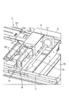
図1は、本発明の第1の実施の形態に係る画像形成装置の全体図である。図1において、50は画像形成装置、51は画像形成装置本体であり、画像形成装置本体51の上部には画像読取装置2が収納され、画像読取装置2の下方には不図示の画像形成部が配置されている。また、1は画像形成装置本体51の前面を形成する前面カバー、1A、1Bは画像形成装置本体51の上面を形成する第1及び第2上面カバーである。
FIG. 1 is an overall view of an image forming apparatus according to a first embodiment of the present invention. In FIG. 1,
図2は、画像形成装置本体51から第1上面カバー1Aを取り外した状態を示す図であり、図3は図2の要部拡大図である。図2及び図3において、3は画像読取装置2を画像形成装置本体51に取り付けるための取り付け部材、9は画像形成装置本体51の背面を形成する背面カバーである。また、19は画像読取装置2の下方に設けられ、シートに画像を形成する際、シートにトナー像を定着させるための不図示の定着器からの熱を外部に排出するための排熱ダクトである。
2 is a view showing a state in which the first
Sは、少なくとも画像形成装置本体51の外面を形成する板状部材である前面カバー1、上面カバー1A(図1参照)及び背面カバー9と、画像読取装置本体2Aとにより形成される閉鎖空間である。なお、本実施の形態において、閉鎖空間Sは、前面カバー1、上面カバー1A、背面カバー9及び画像読取装置本体2Aの他、取り付け部材3と、排熱ダクト19の側面とにより形成されている。
S is a closed space formed by the
14は、外気を吸引して閉鎖空間Sに送り込んで本体枠体に開けられた穴8によって直線状の空気流11を確保し、さらに画像読取装置本体2Aを冷却するための第1冷却部である吸引ファンである。13は閉鎖空間Sに送り込まれた外気を画像読取装置内部に送り込んで画像読取装置内部を冷却するための第2冷却部である2つの送風ファンであり、この送風ファン13は画像読取装置本体2Aと閉鎖空間Sとの間に配置されている。
なお、画像読取装置本体2Aは、図4に示すように、不図示のプラテンガラス上に載置された原稿に対して光を照射する不図示の、例えばハロゲンランプ等の高照度のランプを備えた光源部及び例えばミラー等の反射部材を備えた第1キャリッジ4を備えている。さらに、原稿からの反射光を第1キャリッジ4を介してCCD(センサ)5に導く不図示の第2キャリッジを備えている。
As shown in FIG. 4, the image reading apparatus
そして、プラテンガラス上に載置された原稿の画像を読み取る際には、第1及び第2キャリッジを副走査方向に移動させ、このように移動する際に、プラテンガラス上の原稿の表面に対し光源部から光を照射するようにしている。なお、原稿からの反射光は、第1及び第2キャリッジを介してCCD上にライン結像され、これにより原稿画像が読み取られる。 Then, when reading the image of the document placed on the platen glass, the first and second carriages are moved in the sub-scanning direction, and when moving, the surface of the document on the platen glass is moved. Light is emitted from the light source unit. The reflected light from the original is line-formed on the CCD via the first and second carriages, thereby reading the original image.
また、図4において、7は吸引ファン14により外気を閉鎖空間Sに送り込むため背面カバー9に形成された吸気口、8は送風ファン13により送り込まれた外気を直線状の空気流にするため本体枠に形成された穴である。また、20は画像読取装置本体2Aの送風ファン13に面する側面に形成された外気取り込み穴、21は画像読取装置本体2Aの外気取り込み穴20と対向する位置に設けられた外気吹き出し穴、10は背面カバー9に形成された排気口である。
In FIG. 4, 7 is an intake port formed in the
ところで、既述したように光源部を点灯させると、光源部から熱が発生し、原稿画像を読み取るため、第1及び第2キャリッジを矢印Aに示す副走査方向に移動させると、光源部から熱が画像読取装置内全体へ放熱される。また、CCD5からも熱が発生し、このCCD5からの熱は不図示の放熱板から画像読取装置内へ放熱される。
By the way, as described above, when the light source unit is turned on, heat is generated from the light source unit and the original image is read. Therefore, when the first and second carriages are moved in the sub-scanning direction indicated by the arrow A, the light source unit Heat is dissipated throughout the image reading apparatus. Also, heat is generated from the
ここで、本実施の形態において、このような光源部及び放熱板からの放熱により画像読取装置2の画像読取精度が低下することがないよう、吸引ファン14及び送風ファン13を駆動し、画像読取装置本体2Aの冷却を行うようにしている。
Here, in the present embodiment, the
次に、このような吸引ファン14及び送風ファン13による画像読取装置2の冷却動作について説明する。
Next, the cooling operation of the
まず、画像読取装置2が駆動された後、所定のタイミングで吸引ファン14を駆動する。これにより、図4に示すように、吸引ファン14により閉鎖空間Sに外気が送り込まれ、本体枠体に開けられた穴8によって閉鎖空間Sでは直線状の空気流11が確保される。
First, after the
また、この状態で2つの送風ファン13が駆動されると、直線状の空気流11の一部が送風ファン13により空気流12が生じ、この送風ファン13による空気流12が外気取り込み穴20から画像読取装置内に送り込まれる。
Further, when the two
そして、送風ファン13により送り込まれた外気は、画像読取装置内部において空気流15となってCCD5、第1キャリッジ4の光源部等に当たり、CCD5、光源部等を冷却すると共に、CCD5、光源部等から放熱された熱を画像読取装置外に排出する。これにより、画像読取装置内部をムラなく冷却することができる。
The outside air sent by the
なお、このようにCCD5、光源部等を冷却した外気は、外気吹き出し穴21から排出され、この排気空気流16は背面カバー9に形成された排気口10から画像形成装置外へ排気される。
The outside air that has cooled the
このように、背面カバー9と、前面カバー1と、第1上面カバー1Aと、画像読取装置本体2Aと、取り付け部材3と、排熱ダクト19とにより閉鎖空間Sを形成することにより、専用ダクトが不要となるため、部品代が削減でき、また省スペース化が可能となる。
As described above, the closed space S is formed by the
また、閉鎖空間Sから取り込まれる外気を、画像読取装置内に送り込むようにすることにより、画像読取装置全体を冷却することができ、画像読取装置2の冷却ムラを低減することができる。さらに、画像読取装置全体を外気により冷却することで、定着部からの排熱の影響も低減することができる。
Further, by sending the outside air taken in from the closed space S into the image reading device, the entire image reading device can be cooled, and uneven cooling of the
さらに、画像読取装置2の発熱源である光源部に当てることにより、光源部と原稿面の間に発生する陽炎を低減させることができる。これにより、画像読取装置2の画像読取精度を向上させることができ、画像形成装置1によりシート上に形成される画像品質を向上させることができる。また、CCD放熱板を外気取り込み穴20の近傍に配置するようにすれば、CCD放熱板を外気により効率的に冷却することができる。
Furthermore, by applying the light to the light source unit that is a heat generation source of the
このように、本実施の形態では、閉鎖空間Sを背面カバー9、前面及び第1上面カバー1,1A、画像読取装置本体2A、取り付け部材3及び排熱ダクト19により形成すると共に、閉鎖空間Sに送りこまれた外気を画像読取装置内部に送り込むようしている。これにより、画像形成装置本体内に収納された画像読取装置2を、大型化することなく、かつ冷却ムラが生じることなく冷却することができる。
Thus, in the present embodiment, the closed space S is formed by the
次に、本発明の第2の実施の形態について説明する。 Next, a second embodiment of the present invention will be described.
図5は、本実施の形態に係る画像形成装置の斜視図であり、画像読取装置本体2Aの上方を覆う上面カバー1Bを取り外した状態を示している。図6は、本実施の形態に係る画像形成装置の上面カバー1A,1Bを取り外した状態を示す平面図である。なお、図5及び図6において、既述した図1及び図4と同一符号は、同一又は相当部分を示している。
FIG. 5 is a perspective view of the image forming apparatus according to the present embodiment, and shows a state in which the
図5において、S’は、閉鎖空間を示している。この閉鎖空間S’は、前面カバー1、第1及び第2上面カバー1A,1B、画像読取装置本体2A、取り付け部材3、背面カバー9及び排熱ダクト19の側面により画像読取装置本体2Aを取り囲むように形成されている。
In FIG. 5, S ′ indicates a closed space. The closed space S ′ surrounds the image reading device
ここで、本実施の形態において、閉鎖空間S’は、図6に示すようにそれぞれ連通する第1〜第4閉鎖空間S1〜S4により構成されている。なお、第1閉鎖空間S1は、既述した第1の実施の形態と同様に、前面カバー1と、第1上面カバー1Aと、画像読取装置本体2Aと、取り付け部材3と、背面カバー9と、排熱ダクト19の側面とにより形成されるものである。
Here, in the present embodiment, the closed space S ′ is configured by first to fourth closed spaces S1 to S4 that communicate with each other as shown in FIG. 6. The first closed space S1 includes the
第2閉鎖空間S2は、背面カバー9と、第2上面カバー1Bと、画像読取装置本体2Aと、取り付け部材3とにより形成されるものである。第3閉鎖空間S3は、第2上面カバー1Bと、画像読取装置本体2Aと、取り付け部材3と、前面カバー1とにより形成されるものである。
The second closed space S2 is formed by the
第4閉鎖空間S4は、第2上面カバー1Bと、画像読取装置本体2Aと、取り付け部材3と、前面カバー1と、背面カバー9とにより形成されるものである。そして、この第4閉鎖空間S4に吸引ファン14が設けられている。
The fourth closed space S4 is formed by the second
なお、20Aは第4閉鎖空間S4と画像読取装置内部を連通する外気取り込み穴、21Aは第1閉鎖空間S1と画像読取装置内部を連通する外気吐き出し穴である。そして、本実施の形態においては、これら外気取り込み穴20Aと、外気吐き出し穴21Aにより外気を画像読取装置内部に送り込んで画像読取装置本体内部を冷却する第2冷却部が構成される。
ここで、このように閉鎖空間S’を構成することにより、吸引ファン14により外気を第4閉鎖空間S4に吸い込むと、外気は空気流11としての第4閉鎖空間S4に連通する第2及び第3閉鎖空間S2,S3を流れて第1閉鎖空間S1に流れるようになる。そして、この後、この空気流11は、排気空気流16となって背面カバー9に形成された排気口10から画像形成装置外へ排気される。
Here, if the outside air is sucked into the fourth closed space S4 by the
ここで、このように外気が、空気流11として第1〜第3閉鎖空間S1〜S3を流れると共に、排気空気流16となって第1閉鎖空間S1を流れることにより、画像読取装置本体2Aの周囲に外気が流れ画像読取装置本体2Aが冷却される。
Here, the outside air flows in the first to third closed spaces S1 to S3 as the
また、吸引ファン14にて外気を吸い込むと、外気は、第4閉鎖空間S4に臨む画像読取装置側面に形成された外気取り込み穴20Aから画像読取装置内に流れ込む。そして、このように画像読取装置内に流れ込んだ外気は、画像読取装置内において空気流21となってCCD5、第1キャリッジ4の光源部及び光源部より放熱された熱をムラなく冷却することができる。
When the outside air is sucked in by the
なお、このようにCCD5、光源部等を冷却した外気は、外気吹き出し穴21Aから第1閉鎖空間S1に排出され、この排気空気流16は背面カバー9に形成された排気口10から画像形成装置外へ排気される。
The outside air that has cooled the
このように、本実施の形態においては、画像読取装置本体2Aを取り囲むように閉鎖空間S’を形成して画像読取装置本体2Aを冷却するようにしている。さらに、閉鎖空間S’に送りこまれた外気を、外気取り込み穴20Aと外気吐き出し穴21Aにより構成される第2冷却部により、外気を画像読取装置内部に送り込んで画像読取装置本体内部を冷却するようにしている。
As described above, in the present embodiment, the image reading apparatus
これにより、画像読取装置2を、大型化することなく、かつ冷却ムラが生じることなく冷却できる。また、本実施の形態においては、外気取り込み穴20Aの近傍に第1キャリッジ4が配置しており、これにより効率的に光源部を冷却することができる。
Thereby, the
1 前面カバー
1A 第1上面カバー
1B 第2上面カバー
2 画像読取装置
2A 画像読取装置本体
3 取り付け部材
4 第1キャリッジ
5 CCD
9 背面カバー
13 送風ファン
14 吸引ファン
19 排熱ダクト
20,20A 外気取り込み穴
21,21A 外気吹き出し穴
50 画像形成装置
51 画像形成装置本体
S,S’ 閉鎖空間
DESCRIPTION OF
9 Back cover 13
Claims (6)
前記装置本体内に設けられ、前記装置本体の外面を形成するカバーと、前記装置本体内に前記画像読取装置を取り付ける取り付け部材と、前記画像読取装置本体とにより形成される閉鎖空間と、
前記閉鎖空間に外気を送り込み、前記外気により前記画像読取装置を冷却する第1冷却部と、
前記第1冷却部によって前記閉鎖空間に送りこまれた外気を画像読取装置内部に送り込んで前記画像読取装置内部を冷却する第2冷却部と、
を備えたことを特徴とする画像形成装置。 In an image forming apparatus comprising an image forming unit and an image reading device, wherein the image reading device is housed in the apparatus main body,
A closed space formed by a cover provided in the apparatus main body and forming an outer surface of the apparatus main body, an attachment member for attaching the image reading apparatus in the apparatus main body, and the image reading apparatus main body;
A first cooling unit that sends outside air into the closed space and cools the image reading device with the outside air;
A second cooling unit for sending outside air sent into the closed space by the first cooling unit into the image reading device to cool the inside of the image reading device;
An image forming apparatus comprising:
前記装置本体内に設けられ、前記装置本体の外面を形成するカバーと、前記装置本体内に前記画像読取装置を取り付ける取り付け部材と、前記画像読取装置本体とにより形成され、前記画像読取装置を囲むよう形成された閉鎖空間と、
前記閉鎖空間に外気を送り込み、前記外気により前記画像読取装置を冷却する冷却部と、を有し、
画像読取装置内部と前記画像読取装置を囲む前記閉鎖空間とが連通するように前記画像読取装置本体に外気取り込み穴を形成すると共に、前記画像読取装置本体に前記外気取り込み穴に対向して外気吹き出し穴を形成し、前記冷却部によって前記閉鎖空間に送りこまれた外気を画像読取装置内部に送り込んで前記画像読取装置内部を冷却することを特徴とする画像形成装置。 In an image forming apparatus comprising an image forming unit and an image reading device, wherein the image reading device is housed in the apparatus main body,
A cover provided in the apparatus main body and forming an outer surface of the apparatus main body, a mounting member for attaching the image reading apparatus in the apparatus main body, and the image reading apparatus main body, and surrounding the image reading apparatus. A closed space formed as follows,
The closed space fed with outside air, have a, a cooling unit that cools the image reading apparatus by the ambient air,
An outside air intake hole is formed in the image reading apparatus main body so that the inside of the image reading apparatus and the closed space surrounding the image reading apparatus communicate with each other, and an outside air blowout is opposed to the outside air intake hole in the image reading apparatus main body. An image forming apparatus characterized in that a hole is formed and the inside of the image reading apparatus is cooled by sending outside air sent into the closed space by the cooling unit into the image reading apparatus.
Priority Applications (1)
| Application Number | Priority Date | Filing Date | Title |
|---|---|---|---|
| JP2007020125A JP5006660B2 (en) | 2007-01-30 | 2007-01-30 | Image forming apparatus |
Applications Claiming Priority (1)
| Application Number | Priority Date | Filing Date | Title |
|---|---|---|---|
| JP2007020125A JP5006660B2 (en) | 2007-01-30 | 2007-01-30 | Image forming apparatus |
Publications (3)
| Publication Number | Publication Date |
|---|---|
| JP2008185841A JP2008185841A (en) | 2008-08-14 |
| JP2008185841A5 JP2008185841A5 (en) | 2010-03-11 |
| JP5006660B2 true JP5006660B2 (en) | 2012-08-22 |
Family
ID=39728921
Family Applications (1)
| Application Number | Title | Priority Date | Filing Date |
|---|---|---|---|
| JP2007020125A Expired - Fee Related JP5006660B2 (en) | 2007-01-30 | 2007-01-30 | Image forming apparatus |
Country Status (1)
| Country | Link |
|---|---|
| JP (1) | JP5006660B2 (en) |
Family Cites Families (4)
| Publication number | Priority date | Publication date | Assignee | Title |
|---|---|---|---|---|
| JPH08163322A (en) * | 1994-12-09 | 1996-06-21 | Dainippon Screen Mfg Co Ltd | Image input device |
| JPH11194701A (en) * | 1997-12-26 | 1999-07-21 | Canon Inc | Image reader |
| JP2001217974A (en) * | 2000-02-03 | 2001-08-10 | Fuji Xerox Co Ltd | Image reader |
| JP4532851B2 (en) * | 2003-06-06 | 2010-08-25 | 株式会社リコー | Image forming apparatus |
-
2007
- 2007-01-30 JP JP2007020125A patent/JP5006660B2/en not_active Expired - Fee Related
Also Published As
| Publication number | Publication date |
|---|---|
| JP2008185841A (en) | 2008-08-14 |
Similar Documents
| Publication | Publication Date | Title |
|---|---|---|
| EP1860496B1 (en) | Video projector | |
| JP2006106272A (en) | Display apparatus | |
| JP5004028B2 (en) | Image reading device | |
| JP5706093B2 (en) | Image reading device | |
| US9591165B2 (en) | Image reading apparatus having a blast mechanism | |
| JP2014146742A (en) | Head-up display | |
| JP5006660B2 (en) | Image forming apparatus | |
| US20160187942A1 (en) | Mechanism for sending air in apparatus for reading images and apparatus for reading images | |
| JP5408884B2 (en) | Image forming apparatus and electronic apparatus | |
| KR100434693B1 (en) | Image forming apparatus having ventilating device | |
| US7866825B2 (en) | Blind for a projector | |
| US9488900B2 (en) | Projection apparatus including light sources and heat radiating members | |
| JP2001217974A (en) | Image reader | |
| JP2016071281A (en) | Image forming apparatus | |
| JP4680090B2 (en) | Image reading apparatus and image forming apparatus | |
| US7695142B2 (en) | Projector having a metal plate between a bottom surface of a projector main body and a lamp unit | |
| JP2004045506A (en) | Image reader | |
| JP3885433B2 (en) | Copier and image reading apparatus | |
| JPH08163322A (en) | Image input device | |
| JP4655639B2 (en) | Image forming apparatus | |
| JP4095327B2 (en) | Image reading apparatus and image forming apparatus | |
| JP2008083301A (en) | Heat exhaust device and image forming apparatus | |
| JP2006196979A (en) | Image reading apparatus and image forming apparatus | |
| JP6422031B2 (en) | Illumination apparatus, image reading apparatus, and image forming apparatus | |
| US20200050125A1 (en) | Image forming apparatus |
Legal Events
| Date | Code | Title | Description |
|---|---|---|---|
| A621 | Written request for application examination |
Free format text: JAPANESE INTERMEDIATE CODE: A621 Effective date: 20091218 |
|
| A521 | Written amendment |
Free format text: JAPANESE INTERMEDIATE CODE: A523 Effective date: 20100121 |
|
| A131 | Notification of reasons for refusal |
Free format text: JAPANESE INTERMEDIATE CODE: A131 Effective date: 20111101 |
|
| A521 | Written amendment |
Free format text: JAPANESE INTERMEDIATE CODE: A523 Effective date: 20111227 |
|
| RD05 | Notification of revocation of power of attorney |
Free format text: JAPANESE INTERMEDIATE CODE: A7425 Effective date: 20120125 |
|
| RD03 | Notification of appointment of power of attorney |
Free format text: JAPANESE INTERMEDIATE CODE: A7423 Effective date: 20120203 |
|
| TRDD | Decision of grant or rejection written | ||
| A01 | Written decision to grant a patent or to grant a registration (utility model) |
Free format text: JAPANESE INTERMEDIATE CODE: A01 Effective date: 20120522 |
|
| A01 | Written decision to grant a patent or to grant a registration (utility model) |
Free format text: JAPANESE INTERMEDIATE CODE: A01 |
|
| A61 | First payment of annual fees (during grant procedure) |
Free format text: JAPANESE INTERMEDIATE CODE: A61 Effective date: 20120525 |
|
| FPAY | Renewal fee payment (event date is renewal date of database) |
Free format text: PAYMENT UNTIL: 20150601 Year of fee payment: 3 |
|
| R151 | Written notification of patent or utility model registration |
Ref document number: 5006660 Country of ref document: JP Free format text: JAPANESE INTERMEDIATE CODE: R151 |
|
| FPAY | Renewal fee payment (event date is renewal date of database) |
Free format text: PAYMENT UNTIL: 20150601 Year of fee payment: 3 |
|
| LAPS | Cancellation because of no payment of annual fees |