JP5003032B2 - Control device for automatic transmission - Google Patents
Control device for automatic transmission Download PDFInfo
- Publication number
- JP5003032B2 JP5003032B2 JP2006180128A JP2006180128A JP5003032B2 JP 5003032 B2 JP5003032 B2 JP 5003032B2 JP 2006180128 A JP2006180128 A JP 2006180128A JP 2006180128 A JP2006180128 A JP 2006180128A JP 5003032 B2 JP5003032 B2 JP 5003032B2
- Authority
- JP
- Japan
- Prior art keywords
- vehicle
- automatic transmission
- neutral control
- deceleration
- control
- Prior art date
- Legal status (The legal status is an assumption and is not a legal conclusion. Google has not performed a legal analysis and makes no representation as to the accuracy of the status listed.)
- Expired - Fee Related
Links
Images


Description
本発明は、自動変速機の制御装置に関し、特に、プロペラシャフトを有する後輪駆動車(FR:Front engine Rear drive)において、急制動に伴い駆動伝達系に蓄積される捩りエネルギによるショックによる不快感を搭乗者に与えない制御装置に関する。 The present invention relates to an automatic transmission control device, and in particular, in a rear wheel drive vehicle (FR) having a propeller shaft, discomfort due to shock due to torsional energy accumulated in a drive transmission system due to sudden braking. The present invention relates to a control device that does not give the passengers.
自動変速機に電磁弁を搭載し、外部から電気信号を入力して変速操作に関する変数、たとえば、変速段、油圧レベル、変速操作の時定数やタイミング等をECU(Electronic Control Unit)により調整する自動変速機が実用化されている。このようなECUにより自動変速機の運転状態を種々の状態へと確実かつ速やかに移行可能である。また、ECUには、CPU(Central Processing Unit)が組み込まれているので、プログラムにより制御が可能であるから、プログラムや種々の定数の変更を通じて、自動変速機の運転状態をきめ細かく設定すれば、車両の走行状態やエンジンの負荷状態に対応させて最適な性能を自動変速機から引き出すことが可能である。ここで、車両の走行状態とは、車速やステアリング操作、加速減速の頻度やそのレベル、路面状態等であり、エンジンの負荷状態とは、エンジンの回転数、スロットル開度、アクセルペダル踏み込み量、エンジンや自動変速機の入出力軸のトルク等である。 The automatic transmission is equipped with a solenoid valve, and automatically adjusts variables related to gear shifting operations, such as gear speed, hydraulic level, time constants and timing of gear shifting operations, etc., by inputting an electric signal from the outside using an ECU (Electronic Control Unit). A transmission has been put into practical use. With such an ECU, the operating state of the automatic transmission can be reliably and quickly shifted to various states. Moreover, since the ECU (Central Processing Unit) is incorporated in the ECU, it can be controlled by a program. Therefore, if the operating state of the automatic transmission is set finely through changes in the program and various constants, the vehicle The optimum performance can be extracted from the automatic transmission in accordance with the running state of the vehicle and the load state of the engine. Here, the running state of the vehicle is the vehicle speed, steering operation, acceleration / deceleration frequency and level, road surface condition, etc., and the engine load state is the engine speed, throttle opening, accelerator pedal depression amount, This is the torque of the input and output shafts of engines and automatic transmissions.
さらに、自動変速機に内蔵された係合要素(クラッチやブレーキ)に供給される油圧レベルは、車両の走行状態やエンジンの負荷状態に適合させてきめ細かく調整される。このように調整することにより、変速ショックの抑制と係合要素の損耗の軽減を両立させて、速やかで円滑な変速を達成することができる。 Furthermore, the hydraulic pressure level supplied to the engagement elements (clutch and brake) incorporated in the automatic transmission is finely adjusted to suit the running state of the vehicle and the load state of the engine. By adjusting in this way, it is possible to achieve both a reduction in shift shock and a reduction in wear of the engagement element, and a quick and smooth shift can be achieved.
このような自動変速機は、エンジンとトルクコンバータ等を介して繋がるとともに複数の動力伝達経路を有してなる変速機構を有して構成され、たとえば、アクセル開度および車速に基づいて自動的に動力伝達経路の切り換えを行なう、すなわち自動的に変速比(走行速度段)の切り換えを行なうように構成される。一般的に、自動変速機を有した車両には運転者により操作されるシフトレバーが設けられ、シフトレバー操作に基づいて変速ポジション(たとえば、後進走行ポジション、ニュートラルポジション、前進走行ポジション)が設定され、このように設定された変速ポジション内(通常は、前進走行ポジション内)において自動変速制御が行なわれる。 Such an automatic transmission has a transmission mechanism that is connected to an engine via a torque converter or the like and has a plurality of power transmission paths. For example, the automatic transmission is automatically based on the accelerator opening and the vehicle speed. The power transmission path is switched, that is, the transmission gear ratio (travel speed stage) is automatically switched. Generally, a vehicle having an automatic transmission is provided with a shift lever operated by a driver, and a shift position (for example, a reverse travel position, a neutral position, a forward travel position) is set based on the shift lever operation. The automatic shift control is performed in the shift position set in this way (usually, in the forward travel position).
このような自動変速機を有した車両において、前進走行ポジションが設定されて車両が停止している状態では、アイドリング回転するエンジンからの駆動力がトルクコンバータを介して変速機に伝達され、これが車輪に伝達されるため、いわゆるクリープ現象が発生する。クリープ現象は、登坂路での停車からの発進をスムーズに行なわせることができるなど、所定条件下では非常に有用なのであるが、車両を停止保持したいときには不要な現象であり、車両のブレーキを作動させてクリープ力を抑えるようになっている。すなわち、エンジンからのクリープ力をブレーキにより抑えるようになっており、その分エンジンの燃費が低下するという問題がある。 In a vehicle having such an automatic transmission, in a state where the forward traveling position is set and the vehicle is stopped, the driving force from the idling engine is transmitted to the transmission via the torque converter, which is the wheel. Therefore, a so-called creep phenomenon occurs. Creep phenomenon is very useful under certain conditions, such as smooth starting from a stop on an uphill road, but it is an unnecessary phenomenon when you want to keep the vehicle stopped, and it activates the vehicle brake To suppress the creep force. That is, the creep force from the engine is suppressed by the brake, and there is a problem that the fuel consumption of the engine is reduced accordingly.
このようなことから、前進走行ポジションにおいて、ブレーキペダルが踏み込まれてブレーキが作動されるとともにアクセルがほぼ全閉となって車両が停止している状態では、前進走行ポジションのまま前進クラッチを解放させて、変速機をニュートラルに近いニュートラル状態として、燃費の向上を図ることが提案されている。 For this reason, in the forward travel position, when the brake pedal is depressed and the brake is activated, and the accelerator is almost fully closed and the vehicle is stopped, the forward clutch is released in the forward travel position. Thus, it has been proposed to improve the fuel consumption by setting the transmission to a neutral state close to neutral.
このようなニュートラル制御といわれる技術が、以下に示す特許文献1に開示されている。
ところで、駆動伝達系の機械要素としてプロペラシャフトを有するFR車においては、制動時に駆動輪(後輪タイヤ)からの駆動力が付加され、捩りエネルギーが蓄えられ易い。これについて、以下に詳しく説明する。 By the way, in an FR vehicle having a propeller shaft as a mechanical element of a drive transmission system, a driving force from a drive wheel (rear wheel tire) is added during braking, and torsional energy is easily stored. This will be described in detail below.
制動時には、後輪タイヤから車両の走行源であるエンジンが駆動されることになる。このときに発生するエネルギーは、制動エネルギー分を差し引いた残留エネルギーであって、この残留エネルギーは、駆動伝達系にたわみを発生させる。駆動伝達系とエンジンとは機械的に接続されているので、エンジンのマウント系の弾性部材(ゴム等)のたわみとなって蓄積される。エンジンのマウント系がたわむと、パワートレーン(エンジンとトランスミッション)は車両の前方方向に移動する傾向になる。このため、トランスミッションとプロペラシャフトとの結合が浅くなる。ただし、マウントの支持方法やパワートレーンたドライブトレーンの構成によっては結合が浅くなるのではなく、逆に突っ込まれた状態になる場合もあり得る。 At the time of braking, the engine that is the vehicle travel source is driven from the rear wheel tire. The energy generated at this time is the residual energy obtained by subtracting the amount of braking energy, and this residual energy generates a deflection in the drive transmission system. Since the drive transmission system and the engine are mechanically connected, they are accumulated as a deflection of an elastic member (rubber or the like) of the engine mount system. When the engine mounting system bends, the power train (engine and transmission) tends to move in the forward direction of the vehicle. For this reason, the coupling between the transmission and the propeller shaft becomes shallow. However, depending on the mount support method and the structure of the drive train that is a power train, the coupling may not be shallow, but may be thrust in reverse.
このような状態(すなわち、上記した状態のうちの結合が浅くなる状態)で、ニュートラル制御を実行すると、この残留エネルギが解放されて、車両の前方方向に移動していたパワートレーンが正規の位置に戻される。このときに、トランスミッションとプロペラシャフトとの結合が浅かった状態から滑らかに摺動して結合状態が正規の状態に戻るとは限らない。トランスミッションのスプラインとプロペラシャフトのスプラインとが互いに噛合った状態(楔を打ち込んだような状態であって瞬間的にあるいは部分的に固着している状態)になっていると、摺動して徐々にエネルギーが解放されるのではなく、一気に解放されてしまう。これにより、異音あるいはショックが発生する。 When neutral control is executed in such a state (that is, a state where the coupling becomes shallower in the above state), this residual energy is released and the power train that has moved in the forward direction of the vehicle is in the normal position. Returned to At this time, the coupling state does not always return to the normal state by smoothly sliding from the state where the coupling between the transmission and the propeller shaft is shallow. If the spline of the transmission and the spline of the propeller shaft are engaged with each other (a state where a wedge is driven and is instantaneously or partially fixed), the spline gradually slides. The energy is not released, but it is released at once. As a result, abnormal noise or shock occurs.
ニュートラル制御のように、通常は車両が完全に停止してブレーキペダルが踏まれていると、すなわち車両が完全に停止している状態で、入力クラッチが解放される。このニュートラル制御の前の制動時において残留エネルギーが蓄積されていると、ニュートラル制御は運転者の操作に関係なく開始されるので、運転者の操作に関係なくかつ車両が完全に停止している状態でショックが発生する。特に、運転者が何ら操作をしていない状態において車両にショックが発生することは好ましくない。 As in neutral control, the input clutch is normally released when the vehicle is completely stopped and the brake pedal is depressed, that is, when the vehicle is completely stopped. If residual energy is accumulated at the time of braking before this neutral control, neutral control is started regardless of the driver's operation, so the vehicle is completely stopped regardless of the driver's operation. A shock occurs. In particular, it is not preferable that a shock occurs in the vehicle when the driver is not performing any operation.
しかしながら、このような問題については、上述したいずれの特許文献においても言及されていない。なお、駆動伝達系に干渉部材としてフレキシブルカップリングを備えるようにしたり、結合部の摺動部分を超低摩擦係数の表面処理を施すようにしたりして、このような問題を解決しようとするとコストがアップする。 However, such a problem is not mentioned in any of the above-mentioned patent documents. In order to solve these problems, the drive transmission system may be provided with a flexible coupling as an interference member, or the sliding portion of the coupling portion may be subjected to a surface treatment with an ultra-low friction coefficient. Is up.
本発明は、上述の課題を解決するためになされたものであって、その目的は、制動時に駆動伝達系に蓄積されたエネルギーによるショックを車両の搭乗者に感じさせないまたは感じさせにくい、自動変速機の制御装置を提供することである。 The present invention has been made to solve the above-described problems, and an object of the present invention is to provide an automatic transmission that does not cause or makes it difficult for a vehicle occupant to feel a shock caused by energy accumulated in a drive transmission system during braking. It is to provide a control device for the machine.
第1の発明に係る制御装置は、車両の発進時に係合される係合要素を有する自動変速機を制御する。この制御装置は、前進走行ポジションで車両の状態が予め定められた条件を満足すると、係合要素を解放するニュートラル制御を実行するように、自動変速機を制御するためのニュートラル制御手段と、ニュートラル制御が実行される前の車両の減速度合いを検出するための検出手段と、減速度合いが予め定められた度合いよりも大きいと、ニュートラル制御実行手段によるニュートラル制御の実行を禁止するための禁止手段とを含む。 A control device according to a first aspect of the invention controls an automatic transmission having an engagement element that is engaged when the vehicle starts. The control device includes a neutral control means for controlling the automatic transmission so as to execute a neutral control for releasing the engagement element when the vehicle state satisfies a predetermined condition at the forward travel position, and a neutral control means. Detecting means for detecting the degree of deceleration of the vehicle before the control is executed, and prohibiting means for prohibiting execution of neutral control by the neutral control executing means when the degree of deceleration is greater than a predetermined degree. including.
第1の発明によると、ニュートラル制御を実行する自動変速機において、ニュートラル制御が実行される前の車両の減速度合いが大きい場合には、以下に示すような不具合が発生し得る。急制動に起因して減速度合いが予め定められた度合いよりも大きいと、駆動伝達系に大きな捩りエネルギーが蓄積される。この状態でニュートラル制御を実行すると(通常、ニュートラル制御は車両が完全に停止している状態で実行されるので)、このショックが、運転者の操作に関係なく(ニュートラル制御は自動的に開始されるので)、停止している車両の搭乗者に伝わってしまう。このため、このような場合には、ニュートラル制御の実行を禁止して、ショックの発生を回避する。さらに、急制動により車輪がロックして車両停止と制御装置が誤認識した場合であっても、急制動中にニュートラル制御を行なわれることを回避でき、捩りエネルギーの解放によるショックが発生するのを回避できる。その結果、制動時に駆動伝達系に蓄積されたエネルギーによるショックを車両の搭乗者に感じさせない、自動変速機の制御装置を提供することができる。 According to the first invention, in the automatic transmission that performs neutral control, the following problems may occur when the degree of deceleration of the vehicle before the neutral control is performed is large. If the degree of deceleration is greater than a predetermined degree due to sudden braking, large torsional energy is accumulated in the drive transmission system. When neutral control is executed in this state (normally, neutral control is executed when the vehicle is completely stopped), this shock is automatically started regardless of the driver's operation (neutral control is automatically started). Therefore, it is transmitted to the passengers of the stopped vehicle. For this reason, in such a case, execution of neutral control is prohibited to avoid occurrence of a shock. Furthermore, even when the wheels are locked due to sudden braking and the vehicle stops and the control device misrecognizes, it is possible to avoid performing neutral control during sudden braking and to prevent shocks due to the release of torsional energy. Can be avoided. As a result, it is possible to provide a control device for an automatic transmission that does not make a vehicle occupant feel a shock due to energy accumulated in the drive transmission system during braking.
第2の発明に係る制御装置は、車両に搭載されたエンジンと駆動輪との間の動力を、係合することにより伝達および解放することにより非伝達のいずれかの状態に切り換える係合要素を有する自動変速機を制御する。この制御装置は、車両の減速度合いを検出するための検出手段と、減速度合いが予め定められた度合いよりも大きいと、車両の動きに対応させて、係合要素を解放させるための制御手段とを含む。 According to a second aspect of the present invention, there is provided a control device comprising: an engagement element that switches power to a non-transmission state by transmitting and releasing a power between an engine mounted on a vehicle and a drive wheel by engagement. Control the automatic transmission that has. The control device includes a detecting unit for detecting the degree of deceleration of the vehicle, and a control unit for releasing the engagement element corresponding to the movement of the vehicle when the degree of deceleration is larger than a predetermined degree. including.
第2の発明によると、急制動に起因して減速度合いが予め定められた度合いよりも大きいと、駆動伝達系に大きな捩りエネルギーが蓄積される。この状態で、たとえばニュートラル制御を実行すると(通常、ニュートラル制御は車両が完全に停止している状態で実行されるので)、このショックが、運転者の操作に関係なく(ニュートラル制御は自動的に開始されるので)、停止している車両の搭乗者に伝わってしまう。このため、このような場合には、車両の動いている状態から停止する直前や停止する時や停止した直後に係合要素を解放させて、動力を非伝達の状態として、ショックを発生させる。このようなタイミングでショックを発生させても、車両が動いていたり、停止した瞬間であったり、停止した直後であるので、ショックを搭乗者が感じにくくすることができる。その結果、制動時に駆動伝達系に蓄積されたエネルギーによるショックを車両の搭乗者に感じさせにくい、自動変速機の制御装置を提供することができる。 According to the second invention, if the degree of deceleration is greater than a predetermined degree due to sudden braking, large torsional energy is accumulated in the drive transmission system. In this state, for example, when neutral control is executed (normally, neutral control is executed when the vehicle is completely stopped), this shock is automatically applied regardless of the driver's operation (neutral control is automatically performed). Will be communicated to the passengers of the stopped vehicle. For this reason, in such a case, the engagement element is released immediately before the vehicle is stopped, when the vehicle is stopped, or immediately after the vehicle is stopped, so that the power is not transmitted and a shock is generated. Even if a shock is generated at such a timing, the vehicle is moving, at the moment of stopping, or immediately after it is stopped, so that the passenger can hardly feel the shock. As a result, it is possible to provide a control device for an automatic transmission that makes it difficult for a vehicle occupant to feel a shock due to energy accumulated in the drive transmission system during braking.
第3の発明に係る制御装置は、車両の発進時に係合される係合要素を有する自動変速機を制御する。この制御装置は、前進走行ポジションで車両の状態が予め定められた条件を満足すると、係合要素を解放するニュートラル制御を実行するように、自動変速機を制御するためのニュートラル制御手段と、ニュートラル制御が実行される前の車両の減速度合いを検出するための検出手段と、減速度合いが予め定められた度合いよりも大きいと、ニュートラル制御実行手段によるニュートラル制御の実行を、車両の動きに対応させて実行するための制御手段とを含む。 A control device according to a third aspect of the invention controls an automatic transmission having an engagement element that is engaged when the vehicle starts. The control device includes a neutral control means for controlling the automatic transmission so as to execute a neutral control for releasing the engagement element when the vehicle state satisfies a predetermined condition at the forward travel position, and a neutral control means. The detecting means for detecting the degree of deceleration of the vehicle before the control is executed, and if the degree of deceleration is greater than a predetermined degree, the neutral control execution by the neutral control executing means is made to correspond to the movement of the vehicle. And control means for executing the program.
第3の発明によると、急制動に起因して減速度合いが予め定められた度合いよりも大きいと、駆動伝達系に大きな捩りエネルギーが蓄積される。この状態で、ニュートラル制御を実行すると(通常、ニュートラル制御は車両が完全に停止している状態で実行されるので)、このショックが、運転者の操作に関係なく(ニュートラル制御は自動的に開始されるので)、停止している車両の搭乗者に伝わってしまう。このため、このような場合には、車両の動いている状態から停止する直前や停止する時や停止した直後にニュートラル制御を実行して、ショックを発生させる。このようなタイミングでショックを発生させても、車両が動いていたり、停止した瞬間であったり、停止した直後であるので、ショックを搭乗者が感じにくくすることができる。その結果、制動時に駆動伝達系に蓄積されたエネルギーによるショックを車両の搭乗者に感じさせにくい、自動変速機の制御装置を提供することができる。 According to the third invention, when the degree of deceleration is larger than a predetermined degree due to sudden braking, large torsional energy is accumulated in the drive transmission system. If neutral control is executed in this state (normally, neutral control is executed when the vehicle is completely stopped), this shock will be triggered regardless of the driver's operation (neutral control starts automatically). Will be transmitted to the passengers of the stopped vehicle. For this reason, in such a case, the neutral control is executed immediately before the vehicle is moving, immediately before the vehicle is stopped, or immediately after the vehicle is stopped to generate a shock. Even if a shock is generated at such a timing, the vehicle is moving, at the moment of stopping, or immediately after it is stopped, so that the passenger can hardly feel the shock. As a result, it is possible to provide a control device for an automatic transmission that makes it difficult for a vehicle occupant to feel a shock due to energy accumulated in the drive transmission system during braking.
第4の発明に係る制御装置においては、第2または3の発明の構成に加えて、制御手段は、車両の停止直前に係合要素を解放するための手段を含む。 In the control device according to the fourth invention, in addition to the configuration of the second or third invention, the control means includes means for releasing the engaging element immediately before the vehicle stops.
第4の発明によると、車両の停止直前に捩り戻しのショックを発生させるので、車両の搭乗者に、このショックを感じさせにくくすることができる。 According to the fourth aspect of the present invention, the untwisting shock is generated immediately before the vehicle is stopped, so that it is difficult for the passenger of the vehicle to feel this shock.
第5の発明に係る制御装置においては、第2または3の発明の構成に加えて、制御手段は、車両の停止時に係合要素を解放するための手段を含む。 In the control device according to the fifth aspect of the invention, in addition to the configuration of the second or third aspect of the invention, the control means includes means for releasing the engaging element when the vehicle is stopped.
第5の発明によると、車両の停止時に捩り戻しのショックを発生させるので、車両の搭乗者に、このショックを感じさせにくくすることができる。 According to the fifth aspect of the invention, the shock of twisting back is generated when the vehicle is stopped, so that it is difficult for the passenger of the vehicle to feel this shock.
第6の発明に係る制御装置においては、第2または3の発明の構成に加えて、制御手段は、車両の停止直後に係合要素を解放するための手段を含む。 In the control device according to the sixth invention, in addition to the configuration of the second or third invention, the control means includes means for releasing the engaging element immediately after the vehicle stops.
第6の発明によると、車両の停止直後に捩り戻しのショックを発生させるので、車両の搭乗者に、このショックを感じさせにくくすることができる。 According to the sixth aspect of the present invention, the untwisting shock is generated immediately after the vehicle stops, so that the passenger of the vehicle can hardly feel the shock.
第7の発明に係る制御装置においては、第1〜6のいずれかの発明の構成に加えて、車両は、プロペラシャフトを含む駆動伝達系を有する後輪駆動車両であって、予め定められた度合いは、減速により駆動伝達系に蓄積された捩りエネルギーが解放されると、車両の搭乗者がショックを感じる度合いである。 In the control device according to the seventh invention, in addition to the configuration of any one of the first to sixth inventions, the vehicle is a rear wheel drive vehicle having a drive transmission system including a propeller shaft, and is predetermined. The degree is such a degree that the vehicle occupant feels a shock when the torsional energy accumulated in the drive transmission system is released by deceleration.
第7の発明によると、減速により駆動伝達系に蓄積された捩りエネルギーが解放されると、車両の搭乗者がショックを感じる度合いであっても、ニュートラル制御を禁止してショックの発生を回避できる。また、車両の動きに合わせて係合要素を解放させてまたはニュートラル制御を実行して捩りエネルギーが解放しても、車両が動いていたり、停止したときや、停止した直後であるので、車両の搭乗者がショックを感じにくくすることができる。 According to the seventh invention, when the torsional energy accumulated in the drive transmission system is released by deceleration, even if the vehicle passenger feels a shock, the neutral control is prohibited and the occurrence of the shock can be avoided. . Even if the torsional energy is released by releasing the engagement element in accordance with the movement of the vehicle or performing neutral control, the vehicle is moving, stopped, or immediately after it is stopped. It can make it difficult for passengers to feel shock.
以下、図面を参照しつつ、本発明の実施の形態について説明する。以下の説明では、同一の部品には同一の符号を付してある。それらの名称および機能も同じである。したがってそれらについての詳細な説明は繰返さない。なお、以下においては、制動と減速とを基本的に同じ意味であるとして説明する。すなわち、以下における減速は、制動に起因するものである。 Hereinafter, embodiments of the present invention will be described with reference to the drawings. In the following description, the same parts are denoted by the same reference numerals. Their names and functions are also the same. Therefore, detailed description thereof will not be repeated. In the following description, it is assumed that braking and deceleration have basically the same meaning. That is, the deceleration in the following is caused by braking.
<第1の実施の形態>
図1を参照して、本発明の第1の実施の形態に係る、有段式の自動変速機の制御装置を搭載した車両について説明する。この車両は、プロペラシャフトを有するFR車両である。なお、本実施の形態に係る自動変速機の制御装置を搭載した車両は、有段式の自動変速機ではなく無段式の自動変速機であってもよい。さらに、以下の説明は、FF(Front engine Front drive)車両を積極的に除外するものではない。
<First Embodiment>
With reference to FIG. 1, a vehicle equipped with a stepped automatic transmission control device according to a first embodiment of the present invention will be described. This vehicle is an FR vehicle having a propeller shaft. The vehicle equipped with the automatic transmission control device according to the present embodiment may be a continuously variable automatic transmission instead of a stepped automatic transmission. Further, the following description does not actively exclude front engine front drive (FF) vehicles.
車両は、エンジン1000と、従動輪でありかつ操舵輪でもある前輪2000と、トランスミッション3000と、プロペラシャフト4000と、ディファレンシャルギヤ5000と、駆動輪である後輪6000と、ECU8000を主たる構成要素とする制御部7000とを含む。
The main components of the vehicle are an
エンジン1000は、インジェクタ(図示せず)から噴射された燃料と空気との混合気を、シリンダの燃焼室内で燃焼させる内燃機関である。燃焼によりシリンダ内のピストンが押し下げられて、クランクシャフトが回転させられる。
トランスミッション3000は、所望のギヤ段を形成することにより、クランクシャフトの回転数を所望の回転数に変速する。トランスミッション3000の出力ギヤは、プロペラシャフト4000を介してディファレンシャルギヤ5000に接続されている。なお、トランスミッション3000を構成する、トルクコンバータ3001およびプラネタリーギヤユニット3002については、後で詳述する。
ディファレンシャルギヤ5000には後輪6000に駆動力を伝達するドライブシャフト5500が連結されている。ドライブシャフト5500を介して、左右の後輪6000に動力が伝達される。なお、トランスミッション3000とプロペラシャフト4000との接続部分、プロペラシャフト4000とディファレンシャルギヤ5000との接続部分、ディファレンシャルギヤ5000とドライブシャフト5500との接続部分において、スプラインが用いられている。
The
ECU8000には、車速センサ8002と、シフトレバー8004のポジションスイッチ8005と、アクセルペダル8006のアクセル開度センサ8007と、ブレーキペダル8008に設けられたストップランプスイッチ8009と、トランスミッション3000の作動油の温度を検出する油温センサ8010とがハーネスなどを介して接続されている。
The
車速センサ8002は、ドライブシャフト5500の回転数から車両の車速を検出し、検出結果を表す信号をECU8000に送信する。シフトレバー8004の位置は、ポジションスイッチ8005により検出され、検出結果を表す信号がECU8000に送信される。シフトレバー8004の位置に対応して、トランスミッション3000のギヤ段が自動で形成される。また、運転者の操作に応じて、運転者が任意のギヤ段を選択できるマニュアルシフトモードを選択できるように構成してもよい。
The
アクセル開度センサ8007は、アクセルペダル8006の開度を検出し、検出結果を表す信号をECU8000に送信する。ストップランプスイッチ8009は、ブレーキペダル8008のオン/オフ状態を検出し、検出結果を表す信号をECU8000に送信する。なお、ストップランプスイッチ8009の代わりに、ブレーキペダル8008のストローク量を検出するストロークセンサを設けてもよい。油温センサ8010は、トランスミッション2000のATF(Automatic Transmission Fluid)の温度を検出し、検出結果を表す信号をECU8000に送信する。
The
ECU8000は、車速センサ8002、ポジションスイッチ8005およびアクセル開度センサ8007、ストップランプスイッチ8009、油温センサ8010などから送られてきた信号、ROM(Read Only Memory)に記憶されたマップおよびプログラムに基づいて、減速時の駆動伝達系に蓄積されたエネルギーが一気に解放されたとしても、車両の搭乗者に、スプラインの固着が一気に外れることによるショックを感じさせないように、トランスミッション3000の油圧回路を制御する。
図2を参照して、トランスミッション3000について説明する。トランスミッション3000は、大きくは、トルクコンバータ3001とプラネタリーギヤユニット3002とから構成される。なお、このトランスミッション3000は6速の自動変速機であるが、本発明の実施の形態に係る制御装置の制御対象は、6速の自動変速機に限定されるものではない。
The
プラネタリーギヤユニット3002は、クランクシャフトに連結された入力軸3100を有するトルクコンバータ3001に接続されている。プラネタリーギヤユニット3002は、遊星歯車機構の第1セット3300と、遊星歯車機構の第2セット3400と、出力ギヤ3500と、ギヤケース3600に固定されたB1ブレーキ3610、B2ブレーキ3620およびB3ブレーキ3630と、C1クラッチ3640およびC2クラッチ3650と、ワンウェイクラッチF3660とを含む。
第1セット3300は、シングルピニオン型の遊星歯車機構である。第1セット3300は、サンギヤS(UD)3310と、ピニオンギヤ3320と、リングギヤR(UD)3330と、キャリアC(UD)3340とを含む。
The
サンギヤS(UD)3310は、トルクコンバータ3001の出力軸3210に連結されている。ピ二オンギヤ3320は、キャリアC(UD)3340に回転自在に支持されている。ピ二オンギヤ3320は、サンギヤS(UD)3310およびリングギヤR(UD)3330と係合している。
Sun gear S (UD) 3310 is coupled to
リングギヤR(UD)3330は、B3ブレーキ3630によりギヤケース3600に固定される。キャリアC(UD)3340は、B1ブレーキ3610によりギヤケース3600に固定される。
Ring gear R (UD) 3330 is fixed to
第2セット3400は、ラビニヨ型の遊星歯車機構である。第2セット3400は、サンギヤS(D)3410と、ショートピニオンギヤ3420と、キャリアC(1)3422と、ロングピ二オンギヤ3430と、キャリアC(2)3432と、サンギヤS(S)3440と、リングギヤR(1)(R(2))3450とを含む。
The
サンギヤS(D)3410は、キャリアC(UD)3340に連結されている。ショートピニオンギヤ3420は、キャリアC(1)3422に回転自在に支持されている。ショートピニオンギヤ3420は、サンギヤS(D)3410およびロングピ二オンギヤ3430と係合している。キャリアC(1)3422は、出力ギヤ3500に連結されている。
Sun gear S (D) 3410 is coupled to carrier C (UD) 3340.
ロングピ二オンギヤ3430は、キャリアC(2)3432に回転自在に支持されている。ロングピ二オンギヤ3430は、ショートピニオンギヤ3420、サンギヤS(S)3440およびリングギヤR(1)(R(2))3450と係合している。キャリアC(2)3432は、出力ギヤ3500に連結されている。
サンギヤS(S)3440は、C1クラッチ3640によりトルクコンバータ3001の出力軸3210に連結される。リングギヤR(1)(R(2))3450は、B2ブレーキ3620により、ギヤケース3600に固定され、C2クラッチ3650によりトルクコンバータ3001の出力軸3210に連結される。また、リングギヤR(1)(R(2))3450は、ワンウェイクラッチF3660に連結されており、1速ギヤ段の駆動時に回転不能となる。
Sun gear S (S) 3440 is coupled to
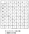
図3に、各変速ギヤ段と、各クラッチおよび各ブレーキの作動状態との関係を表した作動表を示す。「○」は係合を表している。「×」は解放を表している。「◎」はエンジンブレーキ時のみの係合を表している。「△」は駆動時のみの係合を表している。この作動表に示された組合わせで各ブレーキおよび各クラッチを作動させることにより、1速〜6速の前進ギヤ段と、後進ギヤ段が形成される。 FIG. 3 shows an operation table showing the relationship between each gear position and the operation state of each clutch and each brake. “◯” represents engagement. “X” represents release. “◎” represents engagement only during engine braking. “Δ” represents engagement only during driving. By operating each brake and each clutch with the combination shown in this operation table, a forward gear stage of 1st to 6th speed and a reverse gear stage are formed.
B2ブレーキ3620と並列にワンウェイクラッチF3660が設けられているため、作動表に「◎」で示されているように、1速ギヤ段(1ST)形成時のエンジン側からの駆動状態(加速時)にはB2ブレーキ3620を係合させる必要は無い。本実施の形態において、ワンウェイクラッチF3660は、1速ギヤ段の駆動時には、リングギヤR(1)(R(2))3450の回転を防止する。エンジンブレーキを利かせる場合、ワンウェイクラッチF3660は、リングギヤR(1)(R(2))3450の回転を防止しない。
Since the one-way clutch F3660 is provided in parallel with the
トルクコンバータ3001は、入力軸と出力軸とを直結状態にするロックアップクラッチ3203と、入力軸側のポンプ羽根車3201と、出力軸側のタービン羽根車3202と、ワンウェイクラッチ3204を有し、トルク増幅機能を発現するステータ3205とから構成される。トルクコンバータ3001と自動変速機とは、回転軸により接続される。トルクコンバータ3001の出力軸回転数NT(タービン回転数NT)は、タービン回転数センサにより検知される。自動変速機の出力軸回転数NOUTは、出力軸回転数センサにより検知される。
The
図3に示した作動表によると、摩擦要素であるクラッチ要素(図中のC1〜C2)や、ブレーキ要素(B1〜B3)、ワンウェイクラッチ要素(F)が、どのギヤ段の場合に係合および解放されるかを示している。車両の発進時に使用される1速時には、クラッチ要素(C1)、ワンウェイクラッチ要素(F)が係合する。これらのクラッチ要素の中で、特に、C1クラッチ3640を前進クラッチや入力クラッチやフォワードクラッチとも呼ばれ、図3の作動表に示すように、パーキング(P)ポジション、後進走行(R)ポジション、ニュートラル(N)ポジション以外の、車両が前進するための変速段を構成する際に必ず係合状態で使用される。 According to the operation table shown in FIG. 3, the clutch elements (C1 to C2 in the figure), the brake elements (B1 to B3), and the one-way clutch element (F) that are friction elements are engaged at any gear stage. And shows what will be released. At the first speed used when the vehicle starts, the clutch element (C1) and the one-way clutch element (F) are engaged. Among these clutch elements, in particular, the C1 clutch 3640 is also called a forward clutch, an input clutch, or a forward clutch. As shown in the operation table of FIG. 3, the parking (P) position, the reverse travel (R) position, the neutral (N) It is always used in the engaged state when configuring a shift stage for the vehicle to move forward, other than the position.
前進走行(D)ポジションであって、車両の状態が予め定められた条件(アクセルオフかつブレーキオンかつブレーキマスタシリンダ圧が所定値以上かつ車速が所定値以下等の条件)を満足して、車両が停止状態にあると判定されると、C1クラッチ3640を解放するように油圧回路を制御して、C1クラッチ3640を所定のスリップ状態にして、ニュートラルに近い状態にする制御をニュートラル制御という。 The vehicle is in the forward travel (D) position and the vehicle condition satisfies a predetermined condition (accelerator-off and brake-on, brake master cylinder pressure is not less than a predetermined value, vehicle speed is not more than a predetermined value, etc.) Is determined to be in a stopped state, the hydraulic circuit is controlled so as to release the C1 clutch 3640, and the C1 clutch 3640 is brought into a predetermined slip state to be close to the neutral state, which is referred to as neutral control.
本実施の形態に係る制御装置であるECU8000は、ニュートラル制御が実行される前に、高速から急減速されて停止した場合には、駆動伝達系に大きな捩りエネルギが蓄積されているので、ニュートラル制御を禁止することが特徴である。以下、この特徴についてフローチャートを用いて説明する。
When the
図4を参照して、本実施の形態に係る制御装置であるECU8000で実行されるプログラムの制御構造について説明する。なお、以下に示すフローチャートにより表わされるプログラムは、所定のサイクルタイムで繰返し実行される。
With reference to FIG. 4, a control structure of a program executed by
ステップ(以下、ステップをSと略す。)100にて、ECU8000は、車速Vを検出する。このとき、ECU8000は、車速センサ8002から入力されるドライブシャフト5500の回転数から車両の車速を検出する。
In step (hereinafter step is abbreviated as S) 100,
S102にて、ECU8000は、車速Vがしきい値V(1)以上であるか否かを判断する。このしきい値V(1)は、高速からの急減速が行なわれたか否かを判断するためのしきい値であって、捩りが解放されると車両にショックを発生させるほどのエネルギーが駆動伝達系に蓄積される程度の速度が設定される。車速Vがしきい値V(1)以上であると(S102にてYES)、処理はS104へ移される。もしそうでないと(S102にてNO)、処理はS110へ移される。
In S102,
S104にて、ECU8000は、ブレーキ信号を検出したか否かを判断する。このとき、ECU8000は、ストップランプスイッチ8009からのブレーキペダル8008のオン状態を検出する信号を受信するとブレーキ信号を検出したと判断する。ブレーキ信号を検出すると(S104にてYES)、処理はS106へ移される。もしそうでないと(S104にてNO)、処理はS104へ戻される。
In S104,
S106にて、ECU8000は、減速度αを算出する。このとき、ECU8000は、たとえば、ブレーキ信号を検出した後に車速Vを検出して、その車速Vを時間微分することにより減速度αを算出する。なお、減速度αは正の値とする。
In S106,
S108にて、ECU8000は、減速度αがしきい値α(TH)(>0)以下であるか否かを判断する。このしきい値α(TH)は高速からの急減速が行なわれたか否かを判断するためのしきい値であって、捩りが解放されると車両にショックを発生させるほどのエネルギーが駆動伝達系に蓄積される程度の減速度が設定される。減速度αがしきい値α(TH)以下、すなわち緩減速であると(S108にてYES)、処理はS110へ移される。もしそうでないと、すなわち急減速であると(S108にてNO)、この処理は終了する。
In S108,
S110にて、ECU8000は、車速Vを検出する。この処理は、S100の処理と同じである。S112にて、ECU8000は、車速Vがしきい値V(2)以下であるか否かを判断する。このしきい値V(2)は、C1クラッチ3640を解放してニュートラル制御を開始するための条件を満足しているか否かを判断するためのしきい値であって、ほぼ0km/hに設定されることが多い。車速Vがしきい値V(2)以下であると(S112にてYES)、処理はS114へ移される。もしそうでないと(S112にてNO)、この処理は終了する。
In S110,
S114にて、ECU8000は、ブレーキ信号を検出したか否かを判断する。この処理は、S104の処理と同じである。ブレーキ信号を検出すると(S114にてYES)、処理はS116へ移される。もしそうでないと(S114にてNO)、この処理は終了する。
In S114,
S116にて、ECU8000は、トランスミッション3000のATF油温Tを検出する。このとき、ECU8000は、油温センサ8010から入力される温度信号に基づいて、トランスミッション2000のATF油温Tを検出する。
In S116,
S118にて、ECU8000は、ATF油温Tがしきい値T(TH)以上であるか否かを判断する。このしきい値T(TH)は、C1クラッチ3640を解放してニュートラル制御を開始するための条件を満足しているか否かを判断するためのしきい値であって、ほぼ速やかにC1クラッチ3640を解放できる程度までATFの粘度が上昇している温度に対応して設定される。ATF油温Tがしきい値T(TH)以上であると(S118にてYES)、処理はS120へ移される。もしそうでないと(S118にてNO)、この処理は終了する。
In S118,
S120にて、ECU8000は、C1クラッチ3640を解放するようにトランスミッション3000の油圧回路に指令信号を出力して、ニュートラル制御を実行する。
In S120,
以上のような構造およびフローチャートに基づく、本実施の形態に係る制御装置が搭載された車両の動作について説明する。 The operation of the vehicle equipped with the control device according to the present embodiment based on the above-described structure and flowchart will be described.
[1−1]低速から停止した後のニュートラル制御
車速Vが検出されて(S100)、車速Vがしきい値V(1)よりも低く(S102にてNO)、たとえこの低速度から急減速が行なわれても、捩りが解放されると車両にショックを発生させるほどのエネルギーが駆動伝達系に蓄積されない。
[1-1] Neutral control after stopping from low speed The vehicle speed V is detected (S100), and the vehicle speed V is lower than the threshold value V (1) (NO in S102). However, when the torsion is released, energy that causes a shock to the vehicle is not accumulated in the drive transmission system.
このため、車速Vがしきい値V(2)以下になり(S112にてYES)、かつ、ブレーキ信号が検出され(S114にてYES)、かつ、ATF油温Tがしきい値T(TH)以上であると(S118にてYES)、ニュートラル制御を開始するための条件が満足されていると判断して、C1クラッチ3640を解放してニュートラル制御が実行される(S120)。なお、速度、ブレーキ信号、ATF油温以外についてのニュートラル制御開始条件を加えても構わない。 Therefore, vehicle speed V is equal to or lower than threshold value V (2) (YES in S112), a brake signal is detected (YES in S114), and ATF oil temperature T is equal to threshold value T (TH ) If above (YES in S118), it is determined that the conditions for starting neutral control are satisfied, and C1 clutch 3640 is released to perform neutral control (S120). Note that neutral control start conditions other than the speed, brake signal, and ATF oil temperature may be added.
これにより、ニュートラル制御が実行されてC1クラッチ3640が解放されて、駆動伝達系の捩りが戻っても、蓄積されたエネルギーが小さいので、ニュートラル制御中に車両の搭乗者がショックを感じることを回避できる。ニュートラル制御を実行するので、燃費の向上を実現できる。 As a result, even if the neutral control is executed and the C1 clutch 3640 is released and the torsion of the drive transmission system returns, the accumulated energy is small so that the vehicle occupant does not feel a shock during the neutral control. it can. Since neutral control is executed, fuel efficiency can be improved.
[1−2]緩減速により停止した後のニュートラル制御
車速Vが検出されて(S100)、車速Vがしきい値V(1)以上であるが(S102にてYES)、この高速度からの減速による減速度αがしきい値α(TH)以下であると、緩やかな減速である(S108にてYES)。この場合の高速度からの減速においては、捩りが解放されても車両にショックを発生させるほどのエネルギーが駆動伝達系に蓄積されない程度の小さな減速度である。
[1-2] Neutral control after stopping by slow deceleration The vehicle speed V is detected (S100), and the vehicle speed V is equal to or higher than the threshold value V (1) (YES in S102). When deceleration α by deceleration is equal to or less than threshold value α (TH), the vehicle is moderately decelerated (YES in S108). In this case, the deceleration from a high speed is a small deceleration that does not accumulate energy in the drive transmission system so as to cause a shock to the vehicle even when the torsion is released.
このため、車速Vがしきい値V(2)以下になり(S112にてYES)、かつ、ブレーキ信号が検出され(S114にてYES)、かつ、ATF油温Tがしきい値T(TH)以上であると(S118にてYES)、ニュートラル制御を開始するための条件が満足されていると判断して、C1クラッチ3640を解放してニュートラル制御が実行される(S120)。なお、速度、ブレーキ信号、ATF油温以外についてのニュートラル制御開始条件を加えても構わない。 Therefore, vehicle speed V is equal to or lower than threshold value V (2) (YES in S112), a brake signal is detected (YES in S114), and ATF oil temperature T is equal to threshold value T (TH ) If above (YES in S118), it is determined that the conditions for starting neutral control are satisfied, and C1 clutch 3640 is released to perform neutral control (S120). Note that neutral control start conditions other than the speed, brake signal, and ATF oil temperature may be added.
これにより、ニュートラル制御が実行されてC1クラッチ3640が解放されて、駆動伝達系の捩りが戻っても、蓄積されたエネルギーが小さいので、ニュートラル制御中に車両の搭乗者がショックを感じることを回避できる。ニュートラル制御を実行するので、燃費の向上を実現できる。 As a result, even if the neutral control is executed and the C1 clutch 3640 is released and the torsion of the drive transmission system returns, the accumulated energy is small so that the vehicle occupant does not feel a shock during the neutral control. it can. Since neutral control is executed, fuel efficiency can be improved.
[1−3]急減速により停止した後のニュートラル制御
車速Vが検出されて(S100)、車速Vがしきい値V(1)以上であって(S102にてYES)、この高速度からの減速による減速度αがしきい値α(TH)より大きいと、急な減速である(S108にてNO)。この場合の高速度からの減速においては、捩りが解放されると車両にショックを発生させるほどのエネルギーが駆動伝達系に蓄積される程度の大きな減速度である。
[1-3] Neutral control after stopping due to sudden deceleration Vehicle speed V is detected (S100), vehicle speed V is equal to or higher than threshold value V (1) (YES in S102), and from this high speed If deceleration α due to deceleration is greater than threshold value α (TH), the vehicle is suddenly decelerating (NO in S108). In this case, the deceleration from a high speed is a large deceleration that causes energy stored in the drive transmission system to generate a shock when the torsion is released.
このため、ニュートラル制御を開始するための条件が満足されているか否かに関わらず、C1クラッチ3640を解放してニュートラル制御が実行されることはない。 For this reason, the C1 clutch 3640 is not released and the neutral control is not executed regardless of whether the condition for starting the neutral control is satisfied.
これにより、車両停止後にニュートラル制御が実行されることがないので、駆動伝達系の捩りが戻って、蓄積されたエネルギーによるショックをニュートラル制御中に搭乗者が感じることを回避できる。 Thereby, since neutral control is not performed after a vehicle stops, it can avoid that a passenger | crew feels during the neutral control that the twist of a drive transmission system returns and the shock by the stored energy is returned.
以上のようにして、本実施の形態に係る自動変速機の制御装置によると、ニュートラル制御中において、減速時に蓄積されたエネルギーによる駆動伝達系の捩りが戻ることに起因するショックを、搭乗者が感じることを回避することができる。 As described above, according to the control apparatus for an automatic transmission according to the present embodiment, during the neutral control, the rider receives a shock caused by the return of torsion of the drive transmission system due to the energy accumulated during deceleration. You can avoid feeling.
なお、このように、制動により急減速した時にニュートラル制御を禁止することで、急制動による車輪ロックにて車両停止と誤認識して急制動中にニュートラル制御を行なってしまい捩りエネルギーの解放によるショックが発生することを防ぐこともできる。 In this way, by prohibiting neutral control when the vehicle is suddenly decelerated due to braking, the vehicle is misrecognized as a vehicle stop by the wheel lock due to sudden braking, and neutral control is performed during sudden braking. Can also be prevented.
<第2の実施の形態>
以下、本発明の第2の実施の形態について説明する。なお、本実施の形態における制御ブロック等は前述の第1の実施の形態と同じである(図1〜図3)。したがって、それらについての詳細な説明はここでは繰返さない。本実施の形態は、前述の第1の実施の形態と一部が異なるプログラムをECU8000が実行する。
<Second Embodiment>
Hereinafter, a second embodiment of the present invention will be described. Note that the control blocks and the like in the present embodiment are the same as those in the first embodiment (FIGS. 1 to 3). Therefore, detailed description thereof will not be repeated here. In the present embodiment,
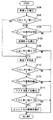
図5を参照して、本実施の形態に係る制御装置であるECU8000で実行されるプログラムの制御構造について説明する。なお、図4に示したフローチャートと同じ処理については同じステップ番号を付してある。それらの処理の内容も同じである。したがって、それらについての詳細な説明はここでは繰返さない。
With reference to FIG. 5, a control structure of a program executed by
S108にて、ECU8000は、減速度αがしきい値α(TH)(>0)以下であるか否かを判断する。減速度αがしきい値α(TH)以下、すなわち緩減速であると(S108にてYES)、処理はS200へ移される。もしそうでないと、すなわち急減速であると(S108にてNO)、処理はS202へ移される。
In S108,
S200にて、ECU8000は、フラグをリセットする。S202にて、ECU8000は、フラグをセットする。このフラグがセットされていると、減速が、高速からの急減速であることを示す。S200およびS202の処理の後、処理はS110へ移される。
In S200,
S204にて、ECU8000は、フラグがセットされているか否かを判断する。フラグがセットされていると、すなわち高速からの急減速であると(S204にてYES)、処理はS206へ移される。もしそうでないと、すなわち、緩減速であると(S204にてNO)、処理はS208に移される。
In S204,
S206にて、ECU8000は、ディレータイマにTM(1)を設定する。S208にて、ECU8000は、ディレータイマにTM(2)を設定する。ここで、ディレータイマは、ニュートラル制御の実行条件が成立してから、トランスミッション3000の油圧回路にC1クラッチ3640を解放する制御信号を出力するまでの遅延時間を管理する減算タイマである。このディレータイマは、ニュートラル制御の実行条件が成立すると減算を開始して、設定されたTM(1)秒またはTM(2)秒の経過後に、ニュートラル制御を実行する。なお、たとえば、TM(2)≫TM(1)≒0である。S206およびS208の処理の後、処理はS210へ移される。
In S206,
S210にて、ECU8000は、ディレータイマがタイムアップしたか否かを判断する。ディレータイマがタイムアップすると(S210にてYES)、処理はS120へ移される。もしそうでないと(S210にてNO)、処理はS210へ戻されて、ディレータイマがタイムアップするまで待つ。
In S210,
以上のような構造およびフローチャートに基づく、本実施の形態に係る制御装置が搭載された車両の動作について、図6を参照して説明する。 The operation of the vehicle equipped with the control device according to the present embodiment based on the above-described structure and flowchart will be described with reference to FIG.
[2−1]低速から停止した後のニュートラル制御
車速Vが検出されて(S100)、車速Vがしきい値V(1)よりも低く(S102にてNO)、たとえこの低速度から急減速が行なわれても、捩りが解放されると車両にショックを発生させるほどのエネルギーが駆動伝達系に蓄積されない。このため、フラグがリセットされる(S200)。
[2-1] Neutral control after stopping from low speed The vehicle speed V is detected (S100), and the vehicle speed V is lower than the threshold value V (1) (NO in S102). However, when the torsion is released, energy that causes a shock to the vehicle is not accumulated in the drive transmission system. For this reason, the flag is reset (S200).
フラグがリセットされているので、(S204にてNO)、ディレータイマにTM(2)が設定される。このため、車速Vがしきい値V(2)以下になり(S112にてYES)、かつ、ブレーキ信号が検出され(S114にてYES)、ATF油温Tがしきい値T(TH)以上であることから(S118にてYES)ニュートラル制御を開始するための条件が満足されていると判断されて、かつ、TM(1)よりも長いTM(2)が設定されたディレータイマがタイムアップすると(S210にてYES)、C1クラッチ3640を解放してニュートラル制御が実行される(S120)。なお、このタイミングが図6のt(3)である。 Since the flag has been reset (NO in S204), TM (2) is set in the delay timer. Therefore, vehicle speed V becomes equal to or lower than threshold value V (2) (YES in S112), a brake signal is detected (YES in S114), and ATF oil temperature T is equal to or higher than threshold value T (TH). Therefore (YES in S118), it is determined that the condition for starting neutral control is satisfied, and the delay timer in which TM (2) longer than TM (1) is set is up. Then (YES in S210), C1 clutch 3640 is released and neutral control is executed (S120). This timing is t (3) in FIG.
これにより、車両が完全に停止して、ニュートラル制御が実行されてC1クラッチ3640が解放されて、駆動伝達系の捩りが戻っても、蓄積されたエネルギーが小さい。このため、車両が完全に停止してニュートラル制御が開始されても、車両の搭乗者がショックを感じることはない。ニュートラル制御を実行するので、燃費の向上を実現できる。 As a result, even when the vehicle is completely stopped, neutral control is executed, the C1 clutch 3640 is released, and the torsion of the drive transmission system returns, the accumulated energy is small. For this reason, even if the vehicle is completely stopped and the neutral control is started, the passenger of the vehicle does not feel a shock. Since neutral control is executed, fuel efficiency can be improved.
なお、このように低速から停止したの場合には、そもそも捩り戻しショックが発生しないので、フラグをセットして、ディレータイマにTM(1)を設定して、図6の時刻t(2)のタイミングで、ニュートラル制御を実行するようにしてもよい。 When stopping from a low speed in this way, a torsional shock does not occur in the first place, so a flag is set, TM (1) is set in the delay timer, and time t (2) in FIG. 6 is set. Neutral control may be executed at the timing.
[2−2]緩減速により停止した後のニュートラル制御
車速Vが検出されて(S100)、車速Vがしきい値V(1)以上であるが(S102にてYES)、この高速度からの減速による減速度αがしきい値α(TH)以下であると、緩やかな減速である(S108にてYES)。この場合の高速度からの減速においては、捩りが解放されても車両にショックを発生させるほどのエネルギーが駆動伝達系に蓄積されない程度の小さな減速度である。このため、フラグがリセットされる(S200)。
[2-2] Neutral control after stopping by slow deceleration The vehicle speed V is detected (S100), and the vehicle speed V is equal to or higher than the threshold value V (1) (YES in S102). When deceleration α by deceleration is equal to or less than threshold value α (TH), the vehicle is moderately decelerated (YES in S108). In this case, the deceleration from a high speed is a small deceleration that does not accumulate energy in the drive transmission system so as to cause a shock to the vehicle even when the torsion is released. For this reason, the flag is reset (S200).
フラグがリセットされているので、(S204にてNO)、ディレータイマにTM(2)が設定される。このため、車速Vがしきい値V(2)以下になり(S112にてYES)、かつ、ブレーキ信号が検出され(S114にてYES)、かつ、ATF油温Tがしきい値T(TH)以上であることから(S118にてYES)ニュートラル制御を開始するための条件が満足されていると判断されて、かつ、TM(1)よりも長いTM(2)が設定されたディレータイマがタイムアップすると(S210にてYES)、C1クラッチ3640を解放してニュートラル制御が実行される(S120)。なお、このタイミングが図6のt(3)である。 Since the flag has been reset (NO in S204), TM (2) is set in the delay timer. Therefore, vehicle speed V is equal to or lower than threshold value V (2) (YES in S112), a brake signal is detected (YES in S114), and ATF oil temperature T is equal to threshold value T (TH ) Because of the above (YES in S118), it is determined that the condition for starting neutral control is satisfied, and a delay timer in which TM (2) longer than TM (1) is set is set. When the time is up (YES in S210), C1 clutch 3640 is released and neutral control is executed (S120). This timing is t (3) in FIG.
これにより、車両が完全に停止して、ニュートラル制御が実行されてC1クラッチ3640が解放されて、駆動伝達系の捩りが戻っても、蓄積されたエネルギーが小さい。このため、車両が完全に停止してニュートラル制御が開始されても、車両の搭乗者がショックを感じることはない。ニュートラル制御を実行するので、燃費の向上を実現できる。 As a result, even when the vehicle is completely stopped, neutral control is executed, the C1 clutch 3640 is released, and the torsion of the drive transmission system returns, the accumulated energy is small. For this reason, even if the vehicle is completely stopped and the neutral control is started, the passenger of the vehicle does not feel a shock. Since neutral control is executed, fuel efficiency can be improved.
なお、[2−1]と同じように、このように緩減速から停止したの場合には、そもそも捩り戻しショックが発生しないので、フラグをセットして、ディレータイマにTM(1)を設定して、図6の時刻t(2)のタイミングで、ニュートラル制御を実行するようにしてもよい。 As in [2-1], when stopping from slow deceleration in this way, a torsional shock does not occur in the first place, so a flag is set and TM (1) is set in the delay timer. Thus, the neutral control may be executed at the timing of time t (2) in FIG.
[2−3]急減速により停止した後のニュートラル制御
車速Vが検出されて(S100)、車速Vがしきい値V(1)以上であって(S102にてYES)、この高速度からの減速による減速度αがしきい値α(TH)より大きいと、急な減速である(S108にてNO)。この場合の高速度からの減速においては、捩りが解放されると車両にショックを発生させるほどのエネルギーが駆動伝達系に蓄積される程度の大きな減速度である。このため、フラグがセットされる(S202)。
[2-3] Neutral control after stopping due to sudden deceleration The vehicle speed V is detected (S100), the vehicle speed V is equal to or higher than the threshold value V (1) (YES in S102), If deceleration α due to deceleration is greater than threshold value α (TH), the vehicle is suddenly decelerating (NO in S108). In this case, the deceleration from a high speed is a large deceleration that causes energy stored in the drive transmission system to generate a shock when the torsion is released. For this reason, a flag is set (S202).
フラグがセットされているので、(S204にてYES)、ディレータイマにTM(1)(≒0)が設定される。このため、車速Vがしきい値V(2)以下になり(S112にてYES)、かつ、ブレーキ信号が検出され(S114にてYES)、かつ、ATF油温Tがしきい値T(TH)以上であることから(S118にてYES)ニュートラル制御を開始するための条件が満足されていると判断されて、かつ、TM(2)よりも短いTM(1)が設定されたディレータイマがタイムアップすると(S210にてYES)、C1クラッチ3640を解放してニュートラル制御が実行される(S120)。なお、このタイミングが図6のt(2)である。 Since the flag is set (YES in S204), TM (1) (≈0) is set in the delay timer. Therefore, vehicle speed V is equal to or lower than threshold value V (2) (YES in S112), a brake signal is detected (YES in S114), and ATF oil temperature T is equal to threshold value T (TH ) Because of the above (YES in S118), it is determined that the condition for starting neutral control is satisfied, and a delay timer in which TM (1) shorter than TM (2) is set is set. When the time is up (YES in S210), C1 clutch 3640 is released and neutral control is executed (S120). This timing is t (2) in FIG.
これにより、車両が完全に停止する直前に(車両の停止状態とニュートラル制御の開始タイミングとは、しきい値V(2)およびTM(1)の設定により、車両が完全に停止する直前、車両が完全に停止する時、車両が完全に停止した直後のいずれも可能である)、ニュートラル制御が実行されてC1クラッチ3640が解放される。このときに、駆動伝達系の捩りが戻って、蓄積された大きなエネルギーが解放されて捩り戻りショックが発生するが、車両が停止する直前であるので、車両の搭乗者がショックを感じることを低減できる(図6の拡大図の実線で示される捩り戻りショック参照)。このため、車両が完全に停止してニュートラル制御が開始された場合(図6の拡大図の一点鎖線で示される捩り戻りショック参照)に比べて、車両の搭乗者がショックを感じることを極力回避することができる。ニュートラル制御を実行するので、燃費の向上を実現できる。 Thus, immediately before the vehicle is completely stopped (the vehicle stop state and the neutral control start timing are determined immediately before the vehicle is completely stopped by setting the threshold values V (2) and TM (1). When the vehicle stops completely, it is possible to do anything immediately after the vehicle stops completely), the neutral control is executed and the C1 clutch 3640 is released. At this time, the torsion of the drive transmission system returns and the accumulated large energy is released to generate a torsional shock, but it is just before the vehicle stops, so that the passenger of the vehicle feels no shock. (See the torsional shock shown by the solid line in the enlarged view of FIG. 6). Therefore, compared with the case where the vehicle is completely stopped and the neutral control is started (refer to the torsional shock indicated by the one-dot chain line in the enlarged view of FIG. 6), the vehicle occupant avoids the shock as much as possible. can do. Since neutral control is executed, fuel efficiency can be improved.
以上のようにして、本実施の形態に係る自動変速機の制御装置によると、ニュートラル制御を実行しつつも、減速時に蓄積されたエネルギーによる駆動伝達系の捩りが戻ることに起因するショックを、搭乗者が感じることを回避することができる。 As described above, according to the control device for an automatic transmission according to the present embodiment, a shock caused by the return of torsion of the drive transmission system due to energy accumulated during deceleration while performing neutral control, It can be avoided that the passenger feels.
なお、第2の実施の形態の[2−3]においては、時刻t(2)からニュートラル制御を開始するのではなく(実質的には同じことになるが)、時刻t(2)においてC1クラッチ3640を解放し、その後に(たとえば時刻t(3)から)ニュートラル制御を開始するようにしてもよい。すなわち、先に、C1クラッチ3640を解放して、車両の走行に紛らせて捩り戻しショックを発生させて搭乗者にこのショックを感じにくくさせつつ、捩り戻しショックを解放した後であって車両が完全に停止してからニュートラル制御を実行するようにしてもよい。
In [2-3] of the second embodiment, the neutral control is not started from time t (2) (substantially the same), but C1 at time t (2).
さらに、第2の実施の形態においてはディレータイマでニュートラル制御の開始を管理したが、このようなタイマに限定されない。車速を監視しておいて、所望の車速になったときにC1クラッチ3640を解放するようにして、捩り戻しショックを車両の走行に紛らせてもよい。 Furthermore, in the second embodiment, the start of neutral control is managed by the delay timer, but the present invention is not limited to such a timer. The vehicle speed may be monitored, and the C1 clutch 3640 may be released when the desired vehicle speed is reached, and the torsional shock may be drowned in the running of the vehicle.
さらに、解放する係合要素はC1クラッチ3640に限定されない。
今回開示された実施の形態はすべての点で例示であって制限的なものではないと考えられるべきである。本発明の範囲は上記した説明ではなくて特許請求の範囲によって示され、特許請求の範囲と均等の意味および範囲内でのすべての変更が含まれることが意図される。
Further, the engagement element to be released is not limited to the
The embodiment disclosed this time should be considered as illustrative in all points and not restrictive. The scope of the present invention is defined by the terms of the claims, rather than the description above, and is intended to include any modifications within the scope and meaning equivalent to the terms of the claims.
1000 エンジン、2000 前輪(従動輪)、3000 トランスミッション、3001 トルクコンバータ、3002 プラネタリーギヤユニット、4000 プロペラシャフト、5000 ディファレンシャルギヤ、6000 後輪(駆動輪)、7000 制御部、8000 ECU。 1000 engine, 2000 front wheel (driven wheel), 3000 transmission, 3001 torque converter, 3002 planetary gear unit, 4000 propeller shaft, 5000 differential gear, 6000 rear wheel (drive wheel), 7000 control unit, 8000 ECU.
Claims (3)
前進走行ポジションで前記車両の状態が予め定められた条件を満足すると、前記係合要素を解放するように前記自動変速機を制御するための制御手段と、
前記車両の減速度合いを検出するための検出手段と、
前記減速度合いが予め定められた度合いよりも大きいと、前記条件の成立時から、前記車両の動きに対応させて前記制御手段により前記係合要素を解放させるまでの時間を計時するための計時手段とを備え、
前記計時手段は、前記車両の停止直前に前記係合要素が解放されるように前記時間を計時し、
前記制御手段は、前記条件の成立時から前記計時手段によって計時された時間が経過すると、前記係合要素を解放するように前記自動変速機を制御する、自動変速機の制御装置。 A control device for an automatic transmission having an engagement element that switches power between an engine mounted on a vehicle and a drive wheel to any state of non-transmission by transmitting and releasing by engagement. ,
Control means for controlling the automatic transmission so as to release the engagement element when the state of the vehicle satisfies a predetermined condition at a forward travel position;
Detecting means for detecting the degree of deceleration of the vehicle;
When the deceleration degree is larger than a predetermined degree, the time measuring means for measuring the time from when the condition is satisfied until the engagement element is released by the control means in response to the movement of the vehicle And
The time measuring means measures the time so that the engagement element is released immediately before the vehicle stops,
The control device of the automatic transmission, wherein the control device controls the automatic transmission so as to release the engaging element when a time measured by the time measuring device elapses from when the condition is satisfied.
前進走行ポジションで前記車両の状態が予め定められた条件を満足すると、前記係合要素を解放するニュートラル制御を実行するように、前記自動変速機を制御するためのニュートラル制御手段と、
前記ニュートラル制御が実行される前の車両の減速度合いを検出するための検出手段と、
前記減速度合いが予め定められた度合いよりも大きいと、前記条件の成立時から、前記車両の動きに対応させて前記ニュートラル制御を実行するまでの時間を計時するための計時手段とを備え、
前記計時手段は、前記車両の停止直前に前記係合要素が解放されるように前記時間を計時し、さらに
前記条件の成立時から前記計時手段によって計時された時間が経過すると、前記ニュートラル制御手段による前記ニュートラル制御を実行するための制御手段を含む、自動変速機の制御装置。 A control device for an automatic transmission having an engagement element that is engaged when a vehicle starts.
A neutral control means for controlling the automatic transmission so as to execute a neutral control for releasing the engagement element when a state of the vehicle in a forward traveling position satisfies a predetermined condition;
Detecting means for detecting the degree of deceleration of the vehicle before the neutral control is executed;
When the degree of deceleration is greater than the predetermined degree, from the time of establishment of the condition, and a time counting means for counting the time until executing the neutral control in correspondence to the movement of the vehicle,
The time measuring means measures the time so that the engaging element is released immediately before stopping the vehicle, and further, when the time counted by the time measuring means elapses from when the condition is satisfied, the neutral control means including control hand stage for executing the neutral control by, the automatic transmission control device.
Priority Applications (1)
| Application Number | Priority Date | Filing Date | Title |
|---|---|---|---|
| JP2006180128A JP5003032B2 (en) | 2006-06-29 | 2006-06-29 | Control device for automatic transmission |
Applications Claiming Priority (1)
| Application Number | Priority Date | Filing Date | Title |
|---|---|---|---|
| JP2006180128A JP5003032B2 (en) | 2006-06-29 | 2006-06-29 | Control device for automatic transmission |
Publications (2)
| Publication Number | Publication Date |
|---|---|
| JP2008008426A JP2008008426A (en) | 2008-01-17 |
| JP5003032B2 true JP5003032B2 (en) | 2012-08-15 |
Family
ID=39066823
Family Applications (1)
| Application Number | Title | Priority Date | Filing Date |
|---|---|---|---|
| JP2006180128A Expired - Fee Related JP5003032B2 (en) | 2006-06-29 | 2006-06-29 | Control device for automatic transmission |
Country Status (1)
| Country | Link |
|---|---|
| JP (1) | JP5003032B2 (en) |
Families Citing this family (2)
| Publication number | Priority date | Publication date | Assignee | Title |
|---|---|---|---|---|
| JP4229155B2 (en) | 2006-09-05 | 2009-02-25 | トヨタ自動車株式会社 | Control device for automatic transmission |
| JP5212079B2 (en) * | 2008-12-19 | 2013-06-19 | トヨタ自動車株式会社 | Vehicle control device |
Family Cites Families (4)
| Publication number | Priority date | Publication date | Assignee | Title |
|---|---|---|---|---|
| JP3052220B2 (en) * | 1991-12-06 | 2000-06-12 | トヨタ自動車株式会社 | Vehicle creep prevention control device |
| JP4032557B2 (en) * | 1999-04-26 | 2008-01-16 | アイシン・エィ・ダブリュ株式会社 | Control device for automatic transmission |
| JP4257019B2 (en) * | 2000-05-25 | 2009-04-22 | 本田技研工業株式会社 | Control device for automatic transmission for vehicle |
| JP3992013B2 (en) * | 2004-04-28 | 2007-10-17 | トヨタ自動車株式会社 | Control device for stepped automatic transmission for vehicle |
-
2006
- 2006-06-29 JP JP2006180128A patent/JP5003032B2/en not_active Expired - Fee Related
Also Published As
| Publication number | Publication date |
|---|---|
| JP2008008426A (en) | 2008-01-17 |
Similar Documents
| Publication | Publication Date | Title |
|---|---|---|
| US7769516B2 (en) | Automatic gear control device | |
| JP4229155B2 (en) | Control device for automatic transmission | |
| JP4211862B1 (en) | Control device for continuously variable transmission | |
| KR100832388B1 (en) | Method for preventing load change impacts in a motor vehicle | |
| JP6603199B2 (en) | Control device for all-wheel drive vehicles | |
| JP4839865B2 (en) | Control device for automatic transmission | |
| JP3704934B2 (en) | Fastening force control device for fluid coupling | |
| US8317654B2 (en) | Method for controlling an automated step-by-step variable speed transmission | |
| JP5003032B2 (en) | Control device for automatic transmission | |
| JP6434345B2 (en) | Transfer clutch control device | |
| JP4640140B2 (en) | Vehicle control device | |
| US20190162304A1 (en) | Control device of vehicle | |
| JP4122668B2 (en) | Shift control device for automatic transmission | |
| JP6065578B2 (en) | Control device and control method for continuously variable transmission | |
| JP2001165299A (en) | Creep force control device of automatic transmission for vehicle | |
| JP4400311B2 (en) | Control device for vehicle with idle stop | |
| JP2019078385A (en) | Vehicular drive device | |
| JP4075671B2 (en) | Vehicle control device | |
| JP4675039B2 (en) | Vehicle driving force control device | |
| JP4735009B2 (en) | Control device for vehicles with automatic transmission | |
| JP2009097614A (en) | Control device of automatic transmission | |
| JP5212079B2 (en) | Vehicle control device | |
| JP2001330142A (en) | Control device for automatic transmission with lockup clutch | |
| JP2006308058A (en) | Automatic transmission control device | |
| JP4924015B2 (en) | Control device for automatic transmission |
Legal Events
| Date | Code | Title | Description |
|---|---|---|---|
| A621 | Written request for application examination |
Free format text: JAPANESE INTERMEDIATE CODE: A621 Effective date: 20080917 |
|
| A977 | Report on retrieval |
Free format text: JAPANESE INTERMEDIATE CODE: A971007 Effective date: 20101217 |
|
| A131 | Notification of reasons for refusal |
Free format text: JAPANESE INTERMEDIATE CODE: A131 Effective date: 20101221 |
|
| A521 | Written amendment |
Free format text: JAPANESE INTERMEDIATE CODE: A523 Effective date: 20110215 |
|
| A131 | Notification of reasons for refusal |
Free format text: JAPANESE INTERMEDIATE CODE: A131 Effective date: 20110823 |
|
| A521 | Written amendment |
Free format text: JAPANESE INTERMEDIATE CODE: A523 Effective date: 20111017 |
|
| TRDD | Decision of grant or rejection written | ||
| A01 | Written decision to grant a patent or to grant a registration (utility model) |
Free format text: JAPANESE INTERMEDIATE CODE: A01 Effective date: 20120424 |
|
| A01 | Written decision to grant a patent or to grant a registration (utility model) |
Free format text: JAPANESE INTERMEDIATE CODE: A01 |
|
| A61 | First payment of annual fees (during grant procedure) |
Free format text: JAPANESE INTERMEDIATE CODE: A61 Effective date: 20120507 |
|
| FPAY | Renewal fee payment (event date is renewal date of database) |
Free format text: PAYMENT UNTIL: 20150601 Year of fee payment: 3 |
|
| FPAY | Renewal fee payment (event date is renewal date of database) |
Free format text: PAYMENT UNTIL: 20150601 Year of fee payment: 3 |
|
| LAPS | Cancellation because of no payment of annual fees |