JP5002787B2 - Speaker device, sound source simulation system, and echo cancellation system - Google Patents
Speaker device, sound source simulation system, and echo cancellation system Download PDFInfo
- Publication number
- JP5002787B2 JP5002787B2 JP2010126391A JP2010126391A JP5002787B2 JP 5002787 B2 JP5002787 B2 JP 5002787B2 JP 2010126391 A JP2010126391 A JP 2010126391A JP 2010126391 A JP2010126391 A JP 2010126391A JP 5002787 B2 JP5002787 B2 JP 5002787B2
- Authority
- JP
- Japan
- Prior art keywords
- bass reflex
- speaker
- reflex port
- speaker unit
- sound
- Prior art date
- Legal status (The legal status is an assumption and is not a legal conclusion. Google has not performed a legal analysis and makes no representation as to the accuracy of the status listed.)
- Active
Links
- 238000004088 simulation Methods 0.000 title claims description 11
- 230000011514 reflex Effects 0.000 claims description 126
- 238000012546 transfer Methods 0.000 claims description 21
- 230000005236 sound signal Effects 0.000 claims description 12
- 230000008859 change Effects 0.000 claims description 10
- 238000012545 processing Methods 0.000 claims description 7
- 230000007423 decrease Effects 0.000 claims description 6
- 238000006243 chemical reaction Methods 0.000 description 27
- 230000006870 function Effects 0.000 description 27
- 230000000694 effects Effects 0.000 description 20
- 239000002184 metal Substances 0.000 description 18
- 238000004080 punching Methods 0.000 description 18
- 230000004807 localization Effects 0.000 description 13
- 210000005069 ears Anatomy 0.000 description 9
- 230000001681 protective effect Effects 0.000 description 9
- 230000003044 adaptive effect Effects 0.000 description 7
- 238000010586 diagram Methods 0.000 description 4
- 230000001603 reducing effect Effects 0.000 description 3
- 238000001914 filtration Methods 0.000 description 2
- 238000009751 slip forming Methods 0.000 description 2
- 238000001228 spectrum Methods 0.000 description 2
- 230000007480 spreading Effects 0.000 description 2
- 241001635598 Enicostema Species 0.000 description 1
- 206010027626 Milia Diseases 0.000 description 1
- 230000009471 action Effects 0.000 description 1
- 238000013459 approach Methods 0.000 description 1
- 230000004323 axial length Effects 0.000 description 1
- 230000005540 biological transmission Effects 0.000 description 1
- 238000013461 design Methods 0.000 description 1
- 238000000034 method Methods 0.000 description 1
- 230000008569 process Effects 0.000 description 1
Images


Classifications
-
- H—ELECTRICITY
- H04—ELECTRIC COMMUNICATION TECHNIQUE
- H04R—LOUDSPEAKERS, MICROPHONES, GRAMOPHONE PICK-UPS OR LIKE ACOUSTIC ELECTROMECHANICAL TRANSDUCERS; DEAF-AID SETS; PUBLIC ADDRESS SYSTEMS
- H04R1/00—Details of transducers, loudspeakers or microphones
- H04R1/20—Arrangements for obtaining desired frequency or directional characteristics
- H04R1/22—Arrangements for obtaining desired frequency or directional characteristics for obtaining desired frequency characteristic only
- H04R1/28—Transducer mountings or enclosures modified by provision of mechanical or acoustic impedances, e.g. resonator, damping means
- H04R1/2807—Enclosures comprising vibrating or resonating arrangements
- H04R1/2815—Enclosures comprising vibrating or resonating arrangements of the bass reflex type
- H04R1/2819—Enclosures comprising vibrating or resonating arrangements of the bass reflex type for loudspeaker transducers
-
- H—ELECTRICITY
- H04—ELECTRIC COMMUNICATION TECHNIQUE
- H04B—TRANSMISSION
- H04B3/00—Line transmission systems
- H04B3/02—Details
- H04B3/20—Reducing echo effects or singing; Opening or closing transmitting path; Conditioning for transmission in one direction or the other
- H04B3/23—Reducing echo effects or singing; Opening or closing transmitting path; Conditioning for transmission in one direction or the other using a replica of transmitted signal in the time domain, e.g. echo cancellers
-
- H—ELECTRICITY
- H04—ELECTRIC COMMUNICATION TECHNIQUE
- H04R—LOUDSPEAKERS, MICROPHONES, GRAMOPHONE PICK-UPS OR LIKE ACOUSTIC ELECTROMECHANICAL TRANSDUCERS; DEAF-AID SETS; PUBLIC ADDRESS SYSTEMS
- H04R1/00—Details of transducers, loudspeakers or microphones
- H04R1/02—Casings; Cabinets ; Supports therefor; Mountings therein
- H04R1/028—Casings; Cabinets ; Supports therefor; Mountings therein associated with devices performing functions other than acoustics, e.g. electric candles
-
- H—ELECTRICITY
- H04—ELECTRIC COMMUNICATION TECHNIQUE
- H04R—LOUDSPEAKERS, MICROPHONES, GRAMOPHONE PICK-UPS OR LIKE ACOUSTIC ELECTROMECHANICAL TRANSDUCERS; DEAF-AID SETS; PUBLIC ADDRESS SYSTEMS
- H04R2499/00—Aspects covered by H04R or H04S not otherwise provided for in their subgroups
- H04R2499/10—General applications
- H04R2499/15—Transducers incorporated in visual displaying devices, e.g. televisions, computer displays, laptops
Landscapes
- Engineering & Computer Science (AREA)
- Signal Processing (AREA)
- Health & Medical Sciences (AREA)
- Otolaryngology (AREA)
- Physics & Mathematics (AREA)
- Acoustics & Sound (AREA)
- Computer Networks & Wireless Communication (AREA)
- Details Of Audible-Bandwidth Transducers (AREA)
- Obtaining Desirable Characteristics In Audible-Bandwidth Transducers (AREA)
- Stereophonic System (AREA)
- Circuit For Audible Band Transducer (AREA)
Description
この発明は、バスレフ構造を備えたスピーカ装置に関するものである。 The present invention relates to a speaker device having a bass reflex structure.
従来、低音増強を行うスピーカ装置として、バスレフポートを設けた位相反転型エンクロージャがある(例えば、特許文献1参照)。 2. Description of the Related Art Conventionally, there is a phase inversion type enclosure provided with a bass reflex port as a speaker device that performs bass enhancement (see, for example, Patent Document 1).
しかし、バスレフポートは、スピーカ装置が小型になり、ポート断面積が小さくなるほどポート内の空気の流速が早くなり、気流によるノイズが発生しやすくなり、ポート開口部において渦輪の空気流の飛び出しが発生する。また、流速が早くなると、ポート内の気流抵抗も増加し、低音増強効果が低下する。したがって、小型のスピーカ装置では、バスレフポートを用いることが少ない。 However, the bass reflex port has a smaller speaker device, and the smaller the cross-sectional area of the port, the faster the air flow rate in the port. To do. Further, when the flow velocity is increased, the airflow resistance in the port is also increased, and the bass enhancement effect is reduced. Therefore, a bass speaker port is rarely used in a small speaker device.
一方、特許文献2には、ポートの形状を工夫することにより流速を抑え、小型のスピーカでもバスレフポートを用いることができるスピーカ装置が提案されている。
On the other hand,
しかしながら、スピーカ装置が小型になるほど、バスレフポートからの再生周波数が高くなる。また、スピーカが小型になるほど、聴取位置とスピーカ装置の位置が接近するため、スピーカユニットとバスレフポートとの見かけ上の角度差が大きくなる。したがって、スピーカ装置が小型になるほど、バスレフポートの定位感が増し、スピーカユニットとバスレフポートは、別の位置に存在する音源として認識されることになる。すると、再生する音源の帯域によって、音源位置がスピーカユニットとバスレフポートとの間を移動することになってしまう。 However, the smaller the speaker device, the higher the reproduction frequency from the bass reflex port. Further, the smaller the speaker is, the closer the listening position and the position of the speaker device are, so that the apparent angle difference between the speaker unit and the bass reflex port increases. Therefore, as the speaker device becomes smaller, the sense of localization of the bass reflex port increases, and the speaker unit and the bass reflex port are recognized as sound sources existing at different positions. Then, the position of the sound source moves between the speaker unit and the bass reflex port depending on the band of the sound source to be reproduced.
そこで、本発明は、バスレフポートに定位感が発生する小型のスピーカユニットを用いる場合においても音源位置が変化しないように構成したスピーカ装置を提供することを目的とする。 Accordingly, an object of the present invention is to provide a speaker device configured so that the position of a sound source does not change even when a small speaker unit that generates a sense of localization is used in a bass reflex port.
この発明は、スピーカユニットとバスレフポートとが設置された位相反転型エンクロージャからなるスピーカ装置に関するものである。バスレフポートは、開口部から該バスレフポートの内部に向かう軸方向に沿って中空断面積が徐々に小さくなる管状体を有し、当該管状体は、中空断面の一方向の長さが前記軸方向に沿って変化しない一定寸法からなる。 The present invention relates to a speaker device including a phase inversion type enclosure in which a speaker unit and a bass reflex port are installed. The bass reflex port has a tubular body whose hollow cross-sectional area gradually decreases along the axial direction from the opening toward the inside of the bass reflex port, and the tubular body has a length in one direction of the hollow cross section in the axial direction. It consists of a fixed dimension that does not change along.
このようなバスレフポートでは、管状体の一方の開口側の断面積がポート内部の断面積と比較して大きいため、管状体に引き込まれる流速は低くなり、管状体の開口端での乱流が抑制される。また、管状体は、中空断面の一方向の長さが前記軸方向に沿って変化しない一定寸法であるため、排気される空気は、一方向に向かって対向する壁面から中空部内の空気へ圧力がかかり続け、他方向に向かって拡散されることになる。このように壁面対方向からの圧力がかかり続け、他方向に向かって拡散されるため、排気流速が急激に低下することになる。これにより、バスレフポートから排出される流速は大きく低下し、空気流はほとんど発生せず、渦輪の空気流の飛び出しも発生しないことになる。 In such a bass reflex port, since the cross-sectional area of one opening side of the tubular body is larger than the cross-sectional area inside the port, the flow velocity drawn into the tubular body is low, and the turbulent flow at the open end of the tubular body is reduced. It is suppressed. Further, since the tubular body has a fixed dimension in which the length in one direction of the hollow cross section does not change along the axial direction, the exhausted air is pressurized from the wall surface facing in one direction to the air in the hollow portion. Will continue to spread and diffuse in the other direction. In this way, pressure from the wall pair direction continues to be applied and diffused in the other direction, so that the exhaust gas flow velocity decreases rapidly. As a result, the flow velocity discharged from the bass reflex port is greatly reduced, almost no air flow is generated, and the air flow of the vortex ring is not generated.
そして、本発明のスピーカ装置では、バスレフポートのエンクロージャ内部側の開口部は、該バスレフポートを挟んでスピーカユニットと反対側に設けられている。このように、バスレフポートの内部側開口部を、バスレフポートを挟んだスピーカユニットの反対側に設けたことにより、もう一方の開口部(外部側開口部)がスピーカユニットに近づくことになる。特に、スピーカユニットとバスレフポートの外部開口部の位置が近接すると、ほぼ1つの点音源として定位することになり、バスレフポートに定位感が発生するような小型スピーカにおいても、周波数によって音源位置が変化しない。 In the speaker device of the present invention, the opening inside the enclosure of the bass reflex port is provided on the opposite side of the speaker unit across the bass reflex port. Thus, by providing the opening on the inner side of the bass reflex port on the opposite side of the speaker unit across the bass reflex port, the other opening (outside opening) approaches the speaker unit. In particular, when the position of the external opening of the speaker unit and the bass reflex port is close, the sound source will be localized as one point sound source, and the position of the sound source changes depending on the frequency even in a small speaker where a sense of localization occurs in the bass reflex port. do not do.
バスレフポートは、具体的には以下の構造を有する。
すなわち、バスレフポートは、前記軸方向が前記スピーカユニットの音波放出方向と直交して設置され、バスレフポートのエンクロージャ外部側の開口部は、前記スピーカユニットの音波放出方向と同一の方向に設けられている。つまり、スピーカユニットの放音方向とバスレフポートの開口部の放音方向が一致する。
Specifically, the bass reflex port has the following structure.
That is, the bass reflex port is installed such that the axial direction is orthogonal to the sound wave emission direction of the speaker unit, and the opening of the bass reflex port outside the enclosure is provided in the same direction as the sound wave emission direction of the speaker unit. Yes. That is, the sound emission direction of the speaker unit matches the sound emission direction of the opening of the bass reflex port.
さらに具体的には、スピーカユニットの中心位置と前記外部開口部の中心位置との距離は、前記スピーカユニットの直径以下である。 More specifically, the distance between the center position of the speaker unit and the center position of the external opening is not more than the diameter of the speaker unit.
本発明のスピーカ装置におけるバスレフポートは、上述のような流速低減作用を有するため、外部開口部の前方にグリルやパンチングメタルなどの外部構造物(開口率50%以下の保護構造物)を近接させたりしても、外部開口部においてはほとんど空気流が存在しないため、排気された渦輪の空気流が保護構造物に衝突して雑音が発生することもない。したがって、ノート型パーソナルコンピュータ等のスピーカ保護用として一般的に用いられている開口率の低いパンチングメタルが設置されていたとしてもバスレフポートを用いることができる。 Since the bass reflex port in the speaker device of the present invention has the above-described flow velocity reducing action, an external structure (a protective structure having an aperture ratio of 50% or less) such as a grill or punching metal is placed in front of the external opening. However, since there is almost no air flow in the external opening, the air flow of the exhausted vortex ring does not collide with the protective structure to generate noise. Accordingly, the bass reflex port can be used even when a punching metal having a low aperture ratio, which is generally used for protecting a speaker of a notebook personal computer or the like, is installed.
また、本発明のスピーカ装置は、仮想音源位置から聴取者に至る伝達関数(頭部伝達関数)を用いて音場再現を行うバーチャルサラウンド等の点音源シミュレーションシステムに好適である。頭部伝達関数による仮想音源のシミュレーションは、点音源を前提としているため、バスレフポートの定位感が増すと、点音源として認識できなくなり、正確な音場再現を行うことができない。しかし、本発明のスピーカ装置であれば、ほぼ1つの点音源として定位することになるため、正確な音場再現を行うことができる。 In addition, the speaker device of the present invention is suitable for a point sound source simulation system such as virtual surround that reproduces a sound field using a transfer function (head related transfer function) from a virtual sound source position to a listener. Since the simulation of a virtual sound source using a head-related transfer function is based on a point sound source, if the bass reflex port is more localized, it cannot be recognized as a point sound source, and accurate sound field reproduction cannot be performed. However, if the speaker device of the present invention is localized as one point sound source, accurate sound field reproduction can be performed.
また、本発明のスピーカ装置は、スピーカからマイクに至る帰還音響系の伝達関数を模擬し、スピーカに供給する音声信号をフィルタ処理することにより擬似エコー成分を生成し、生成した擬似エコー成分をマイクで取得した音声信号から除去するエコーキャンセラに用いる場合にも好適である。 The speaker device of the present invention simulates a transfer function of a feedback acoustic system from the speaker to the microphone, generates a pseudo echo component by filtering the audio signal supplied to the speaker, and generates the generated pseudo echo component by the microphone. It is also suitable for use in an echo canceller that removes from the audio signal acquired in (1).
このエコーキャンセラは、帰還音響系の伝達関数を模擬する適応型フィルタが用いられるが、バスレフポートの定位感が増すと、音源が移動したり、音源が複数存在することになったりするため、伝達関数が頻繁に変化することになる。したがって、適応型フィルタが正確に伝達関数の推定ができなくなり、エコーキャンセル効果が低下する。本発明のスピーカ装置であれば、ほぼ1つの点音源として定位することになるため、正確な伝達関数の推定を行うことができる。 This echo canceller uses an adaptive filter that simulates the transfer function of the feedback acoustic system, but if the bass reflex port has a greater sense of localization, the sound source may move or multiple sound sources may exist. The function will change frequently. Therefore, the adaptive filter cannot accurately estimate the transfer function, and the echo cancellation effect is reduced. Since the speaker device of the present invention is localized as almost one point sound source, an accurate transfer function can be estimated.
この発明によれば、バスレフポートに定位感が発生する小型のスピーカユニットを用いる場合においても音源位置が変化しない。 According to the present invention, the position of the sound source does not change even when a small speaker unit that produces a sense of localization is used in the bass reflex port.
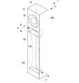
まず、本発明の第1の実施形態に係るスピーカ装置1について、図1および図2を参照して説明する。図1および図2に示すように、スピーカ装置1は位相反転型エンクロージャ(キャビネット)11にスピーカユニットSPおよびバスレフポート10が設置されている。バスレフポート10は、外部開口部17および内部開口部18が形成された構造を有する。
First, a
キャビネット11は、直方体形状からなり、互いに主面が平行な前面板12と背面板13、天面板14と底面板15、および、側面板16Aと側面板16Bにより形成されている。天面板14と底面板15との間隔は、他の板面同士の間隔より長い。実施形態では、天面板14と底面板15とを結ぶ方向を長手方向とし、側面板16Aと側面板16Bとを結ぶ方向を短手方向とし、前面板12と背面板13とを結ぶ方向を奥行き方向と称する。
The
キャビネット11の容積は、スピーカユニットSPの電気的および機械的特性を考慮し、周波数特定を平坦とするために必要な容積に設定される。第1の実施形態では、一例として、直径30mm、奥行21.5mm、実効振動板半径が11.5mm、最低共振周波数300Hz、定格出力2Wのフルレンジスピーカユニットを用い、内容積が80ccの場合にほぼ平坦な周波数特性が得られたものとして説明する。
The volume of the
一般的に、バスレフポートの共振周波数は、スピーカユニットの最低共振周波数の0.7〜0.5倍程度の周波数に設定されるため、第1の実施形態では、バスレフポートの共振周波数を150Hzとする。150Hzから300Hzに至る周波数帯域では、バスレフポート10およびスピーカユニットSPから放出される音の比率は連続的に変化する。この様な低出力、小型のスピーカユニットでは、聴取者は、スピーカ装置に近い位置(例えば750mm離れた位置)で音を聴取することになる。
Generally, the resonance frequency of the bass reflex port is set to a frequency that is approximately 0.7 to 0.5 times the lowest resonance frequency of the speaker unit. Therefore, in the first embodiment, the resonance frequency of the bass reflex port is 150 Hz. To do. In the frequency band from 150 Hz to 300 Hz, the ratio of the sound emitted from the
キャビネット11の長手方向の内寸は、スピーカユニットSPおよびバスレフポート10が長手方向に順に並ぶ長さ以上必要である。キャビネット11の短手方向の内寸は、スピーカユニットSPの幅によって決まる。キャビネット11の奥行きの内寸は、スピーカユニットSPの奥行きによって決まる。キャビネット11はできるだけ薄型、小型に設計することが望ましい。例えば、第1の実施形態では、バスレフポート10は、150Hzで共振させる必要があるため、開口部を除いた長手方向の長さは約100m程度必要である。したがって、長手方向の内寸は161mm(外寸は165mm)、奥行きの内寸は20mm(外寸は24.5mm)、短手方向の内寸は32mm(外寸は35mm)としている。
The inner dimension of the
前面板12は、スピーカユニットSPが設置されるとともに、外部開口部17が形成されており、バッフル板として機能する。ここで、スピーカユニットSPは、前面板12の長手方向の天面板14付近に設置されており、バスレフポート10の外部開口部17は、スピーカユニットSPの直近に形成されており、内部開口部18は、バスレフポート10を挟んでスピーカユニットSPと反対側(底面板15付近)に形成されている。この例では、スピーカユニットSPの中心位置と外部開口部17の中心位置との距離は23.5mmとし、スピーカユニットSPの直径以下となっている。この場合、750mm離れた聴取者の位置において、スピーカユニットSPとバスレフポート10の放出した音の到達時間差(位相差に相当する。)は、1.15μsec程度となる。
The
人の聴覚は150Hz以下の超低域に対して方向感覚を持たないが、第1の実施形態では、バスレフポートの共振周波数を150Hzとしているため、バスレフポート10にも定位感が発生している。すなわち、一般に、人は1600Hz以下の周波数では、位相差によって定位感を得ていると言われているが、150Hz〜1700Hz程度の帯域においては、定位感を得るための両耳の到達時間差の閾値は9μsec程度であることが明らかとされている。特に、持続的なノイズの様な音は、6μsec程度でも定位感を得ることができるとされている(B.C.J.ムーア「聴覚心理学概論」を参照)。
Although human hearing does not have a sense of direction with respect to an ultra-low frequency range of 150 Hz or less, in the first embodiment, the
したがって、スピーカユニットSPの中心位置と外部開口部17の中心位置との距離が遠くなり、聴取位置が近くなると、両耳の到達時間差が大きくなり、再生する音源の帯域によって、音源位置がスピーカユニットとバスレフポートとの間を移動することになってしまう。例えば、第一の実施形態と同じスピーカユニットを用い、同内容積のキャビネットに従来型の直管の円筒バスレフポートを用いて構成したバスレフスピーカの場合には、スピーカユニットSPの中心位置と外部開口部17の中心位置との距離が140mm離れるため、750mm離れた聴取者の位置において、到達時間差は37.7μsecとなり、スピーカユニットSPとバスレフポート10の放出した音を別の音源位置として認識することができるようになってしまう。すると、男性の声のような低い音はバスレフポート側、女性の声のような高い音はスピーカユニット側から聞こえるように感じてしまい、聴感上好ましくない。また、同じ音がスピーカユニットSPとバスレフポート10から同時に放出されると、点音源とみなせないほどの広がり感をもってしまうため、音の明りょう感がなくなり、音質的にも劣化するものと考えられる(ステレオ再生用の音場は、点音源を前提にしている)。
Therefore, when the distance between the center position of the speaker unit SP and the center position of the
しかし、本実施形態のスピーカ装置は、750mm離れた聴取者の位置において、スピーカユニットSPとバスレフポート10の放出した音の到達時間差は、1.15μsec程度となるため、最小閾値とされる6μsecよりもはるかに短い。したがって、ほぼ一つの点音源として認識することができる。
However, in the speaker device according to the present embodiment, the arrival time difference between the sounds emitted from the speaker unit SP and the
次に、バスレフポート10の詳細な構造、機能について説明する。バスレフポート10は、長手方向(軸方向)に延びる形状の主管部100と、該主管部100の軸方向の両端に接続された空気整流器101および空気整流器102とからなる。スピーカユニットSP側の空気整流器101側に外部開口部17が設けられ、空気整流器102側に内部開口部18が設けられている。バスレフポート10は、軸方向がスピーカユニットSPの音波放出方向と直交して設置され、外部開口部17は、軸方向と異なる方向(スピーカユニットSPの音波放出方向)に設けられている。内部開口部18は、キャビネット11の底面から、外部開口部17の軸方向の長さa(および奥行き方向の長さa)と同程度離れている。
Next, the detailed structure and function of the
主管部100、空気整流器101および空気整流器102は、中空の管形状であり、当該中空の長手方向に沿った中心軸が一致するように形成されている。主管部100は、軸方向に垂直な中空断面の形状が円形であり、かつ当該中空断面積が長手方向の各位置で一定の中空管部190からなる。この中空管部190の長さおよび内径は、エンクロージャとして増強したい低音の周波数に基づいて設定される値である。この中空管部190の内径が細いほど主管部100の長さを短くすることができる。中空管部190の内径断面積はスピーカユニットSPの有効面積よりも小さくなるように設定する(例えば、主管部100の中空断面積は、スピーカユニットSPの有効面積の0.2〜1.0倍に設定する)ことが望ましい。本実施形態では、中空管部190の長さは30mm、内径は7mmとしている。
The
空気整流器101は、主管部100の外部開口部17側の開口端に接続されており、主管部100への接続側から内径変換部103および主変換部104が連続的に形成されている。
The
内径変換部103の中空の形状は、主管部100側端部で中空管部190と同じ断面円形状となり、主変換部104側端部で中空管部190の内径と同じか該内径よりも若干長い縦横寸法からなる断面正方形状で形成されている。内径変換部103の壁面131〜134は、内径変換部103の中空が上述のように断面円形状から断面正方形状へ徐々に変化するように成形されている。
The hollow shape of the inner
主変換部104の中空の形状は、内径変換部103側端部で内径変換部103と同じ断面正方形状であり、外部開口部17側端部で内径変換部103側よりも広い面積からなる断面長方形状で形成されている。
The hollow shape of the
主変換部104の中空を形成する壁面141〜144のうち、キャビネット11の奥行き方向に対向する壁面141と壁面142は、内径変換部103の奥行き方向に対向する壁面131と壁面132とにそれぞれ接続する。この際、壁面141と壁面142とは向かい合う面同士が平行になるように設置されている。この構造により、壁面141と壁面142は、対向する面の間隔がどの位置であっても同じとなり、主変換部104は中空形状が奥行き方向に広がらない形状となる。この例では、キャビネット11の短手方向に対向する壁面143と壁面144とは、内径変形部103側から外部開口部17側へ進むにつれて、互いの間隔が指数関数値に準じて広がる形状で形成されている。
Of the wall surfaces 141 to 144 forming the hollow of the
このような構造とすることで、空気整流器101は、主管部100に接続する側から外部開口部17側にかけて、キャビネット11の奥行き方向に対しては壁面の間隔を変化させることなく中空断面積が大きくなる形状となる。
With this structure, the
空気整流器102は、主管部100を挟んでスピーカユニットSPの反対側に接続されており、主管部100への接続側から内径変換部105および主変換部106が連続的に形成されている。
The
内径変換部105の中空の形状は、主管部100側端部で中空管部190と同じ断面円形状となり、主変換部106側端部で中空管部190の内径と同じか該内径よりも若干長い縦横寸法からなる断面正方形状で形成されている。内径変換部105の壁面151〜154は、内径変換部105の中空が上述のように断面円形状から断面正方形状へ徐々に変化するように成形されている。
The hollow shape of the inner
主変換部106の中空の形状は、内径変換部105側端部で内径変換部105と同じ断面正方形状であり、スピーカユニットSP側端部で内径変換部105側よりも広い面積からなる断面長方形状で形成されている。
The hollow shape of the
主変換部106の中空を形成する壁面161〜164のうち、キャビネット11の奥行き方向に対向する壁面161と壁面162は、内径変換部105の奥行き方向に対向する壁面151と壁面152とにそれぞれ接続する。この際、壁面161と壁面162とは向かい合う面同士が平行になるように設置されている。この構造により、壁面161と壁面162は、対向する面の間隔がどの位置であっても同じとなり、主変換部106は中空形状が奥行き方向に広がらない形状となる。キャビネット11の短手方向に対向する壁面163と壁面164とは、内径変形部105側からスピーカユニットSP側へ進むにつれて、互いの間隔が指数関数値に準じて広がる形状で形成されている。
Of the wall surfaces 161 to 164 forming the hollow of the
このような構造とすることで、空気整流器102は、主管部100に接続する側から内部開口部18側にかけて、キャビネット11の奥行き方向に対しては壁面の間隔を変化させることなく中空断面積が大きくなる形状となる。
With such a structure, the
このような構造のエンクロージャでは、スピーカユニットSPが振動することにより、次に示すような動作が生じる。 In the enclosure having such a structure, the following operation occurs when the speaker unit SP vibrates.
図3および図4は、空気整流器102側(内部開口部18)から吸気して、空気整流器101側(外部開口部17)から排気する場合の気流の様子を、従来例の構造と比較して示す説明図である。
3 and 4 show the state of the airflow when air is taken in from the
図3(A)は本実施形態の構成における吸気動作を示し、図3(B)は従来の単純な円筒形状のバスレフポートによる吸気動作を示す。また、図4(A)は本実施形態の構成における排気動作を示し、図4(B)は外部開口端をトランペットのベルのように滑らかに全方向に拡げたバスレフポートによる排気動作を示す。なお、図3および図4において、図中の白抜きヘッドの矢印が気流を示し、矢印方向が気流方向、矢印の長さが流速を示す。 3A shows the intake operation in the configuration of the present embodiment, and FIG. 3B shows the intake operation by a conventional simple cylindrical bass reflex port. 4A shows the exhaust operation in the configuration of the present embodiment, and FIG. 4B shows the exhaust operation by the bass reflex port in which the outer opening end is smoothly expanded in all directions like a trumpet bell. 3 and 4, the arrows of the white heads in the drawings indicate the air flow, the arrow direction indicates the air flow direction, and the length of the arrow indicates the flow velocity.
従来の単純な円筒形状のバスレフポートでは、図3(B)に示すように、吸気時には全方向から空気が流入するため、角に渦が生じ、この渦が雑音を発生させる。 In the conventional simple cylindrical bass reflex port, as shown in FIG. 3B, since air flows in from all directions during intake, a vortex is generated at the corner, and this vortex generates noise.
一方、本実施形態のバスレフポート10では、内部開口部18は、主管部100と比較して中空断面積が大幅に大きい。このため、空気整流器102の内部開口部18側では、吸気流速が非常に低くなり、当該開口端での乱流が殆ど発生しない。なお、空気整流器102の中空断面積は、空気の進行方向に沿って指数関数値に準じて滑らかに小さくなるので、空気整流器102を通過中も乱流が発生しない。
On the other hand, in the
さらに、空気整流器102と主管部100との接続部では、内径変換部105により空気整流器102の主変換部106に対応する断面方形状から主管部100に対応する断面円形状に中空形状が滑らかに変換される。これにより、主管部100に至って空気の流速が増しても、空気整流器102から主管部100への流入時の乱流も発生しない。このように、空気整流器102は、吸気時の乱流を大幅に抑制し、これに基づく雑音の発生を大幅に抑制することができる。
Further, in the connection portion between the
主管部100は、既述の様にスピーカユニットSPの有効面積よりも小さな一定の中空断面積を有する。主管部100は、空気整流器102から流入された空気を所定の流速で流し、空気整流器101へ出力する。この際、主管部100を流れる空気流は壁との間に全方向に均一な圧力を生じているが、主管部100が一定形の円管状であるので主管部100内では乱流が発生することなく、所望の周波数でのヘルムホルツ共振を励起することができる。
As described above, the
従来の単純な円筒形状のバスレフポートでは、外部開口部をグリルやパンチングメタル等の保護構造物で覆うとポート全体の空気抵抗が増大しバスレフ効率が著しく低下してしまう。また、従来の単純な円筒形状のバスレフポートでは、排気時に外部開口端において空気流のほとんどは直進し、開口端周囲の空気を巻き込んで渦輪の空気流を形成する。渦輪は一旦生成されると空気抵抗が非常に小さくなる性質を持つため遠方まで到達する。このため、外部開口部の前面にグリルやパンチングメタル等の保護構造物を設けると、この保護構造物に渦輪空気流が衝突して雑音を発生してしまう。従来のバスレフポートにおいては、外部開口端の角に丸みを持たせたものが多く見られるが、これらは主に外部開口端において吸気時に角で発生する渦による雑音を防ぐためのものであり、排気時に流速を低下させる効果や渦輪空気流の発生を防ぐ効果はほとんどない。例えば、図4(B)のように、外部開口端をトランペットのベルのように滑らかに全方向に拡げた場合、中空断面積の増加が穏やなうちは空気流は中空断面全体に拡がりながら進行し流れは減速してゆくが、しだいに中空断面積の増加が急になり空気流と壁との間の圧力が0となると空気流は壁に沿わず直進し、周囲の空気を巻き込んで渦輪の空気流を形成しポート外部開口部から渦輪空気流が外部に放出されてしまう。このようなポートにおいて、渦輪空気流を発生させずに流速を十分低下させるためには空気流が十分減速するまで壁と空気流の圧力が0とならない様にポートの拡大率を低く抑え徐々にポートの中空断面積を拡大する必要がある。すると、必然的にポートの長軸方向の長さが長くなり、同じバスレフ共振周波数を維持するためにはポートを太くする必要が生じ、ポートが大型化してしまう。このため、外部開口端をトランペットのベルのように滑らかに全方向に拡げたバスレフポートを小型スピーカに適応することは極めて困難と考えられる。 In a conventional simple cylindrical bass reflex port, if the external opening is covered with a protective structure such as a grill or punching metal, the air resistance of the entire port increases and the bass reflex efficiency is significantly reduced. Further, in the conventional simple cylindrical bass reflex port, most of the air flow goes straight at the external opening end during exhaust, and the air around the opening end is entrained to form a vortex ring air flow. Once the vortex ring is generated, it has a property that the air resistance becomes very small, so that it reaches far away. For this reason, if a protective structure such as a grill or punching metal is provided on the front surface of the external opening, a vortex ring air flow collides with the protective structure and generates noise. Many conventional bass reflex ports have rounded corners at the outer opening end, but these are mainly to prevent noise caused by vortices generated at the corners during intake at the outer opening end. There is almost no effect of reducing the flow velocity during exhaust or preventing the generation of vortex ring airflow. For example, as shown in FIG. 4B, when the outer open end is smoothly expanded in all directions like a trumpet bell, the air flow spreads over the entire hollow cross section while the increase in the hollow cross sectional area is moderate. As the flow progresses and decelerates, the hollow cross-sectional area gradually increases, and when the pressure between the air flow and the wall becomes zero, the air flow goes straight along the wall and entrains the surrounding air. A vortex ring air flow is formed, and the vortex ring air flow is discharged to the outside from the port external opening. In such a port, in order to sufficiently reduce the flow velocity without generating a vortex ring air flow, the expansion rate of the port is gradually reduced so that the pressure of the wall and the air flow does not become zero until the air flow is sufficiently decelerated. It is necessary to enlarge the hollow cross-sectional area of the port. As a result, the length of the port in the long axis direction is inevitably increased, and in order to maintain the same bass reflex resonance frequency, the port needs to be thickened, resulting in an increase in the size of the port. For this reason, it is considered extremely difficult to adapt a bass reflex port whose outer opening end is smoothly expanded in all directions like a trumpet bell to a small speaker.
一方、本実施形態のバスレフポートの場合、主管部100と空気整流器101との接続部では、内径変換部103により主管部100に対応する断面円形状から主変換部104に対応する断面方形状に中空形状が滑らかに変換される。
On the other hand, in the case of the bass reflex port of the present embodiment, at the connection portion between the
空気整流器101の主変換部104は、中空断面積が空気の進行方向に沿って指数関数値に準じて滑らかに大きくなる。しかしながら、壁面141と壁面142との間隔が一定であるので、主変換部104内では、壁面141および壁面142方向へ拡散しようとする空気に対して、壁面141および壁面142から圧力が加わり続ける。このため、空気は、互いの距離が徐々に離間する壁面143と壁面144との方向へと押し広げられる。すなわち、主変換部104を流れる空気は、常に壁面141〜144で囲まれた中空断面全体に拡がりながら流れる。このように、中空断面全体に拡がりながら流れる空気に対して、主変換部104では、急激に断面積が大きくなるので、流速は一気に低下する。そして、主変換部104の外部開口部17に達するまでに流速は十分に低下し、排気の流速は主管部100と比較して大幅に低くなり、空気流がほとんど発生しない状態となる。もちろん、主管部100において所望の周波数でのヘルムホルツ共振を励起することができるため、外部開口部17からは、バスレフ効果によって増幅された低音成分が放音される。
The
この際、外部開口部17からは空気流がほとんど発生しないため、バスレフポートの軸方向がスピーカユニットの音波放出方向と直交して設置され、軸方向と異なる方向(例えばスピーカユニットSPの放音方向)に外部開口部17が設けられていたとしても、空気流が内部壁面に衝突して雑音が発生することがない。したがって、バスレフポート10の軸方向とキャビネット11の長手方向とを同一とし、スピーカ装置全体を小型化しながらも、スピーカユニットSPとバスレフポート10の放音方向を一致させることができる。スピーカユニットSPの放音方向とバスレフポートの放音方向を一致させると、より1つの音源として定位し易くなる。
At this time, since almost no air flow is generated from the
さらに、外部開口部17からは渦輪空気流がほとんど発生しないため、外部開口部17の前面にグリルやパンチングメタル等の保護構造物を設けたとしても、この保護構造物に空気が衝突して雑音することはない。特に、開口率の低い(例えば50%以下の)保護構造物を設けると、一般的にはポート全体の気流抵抗が大きくなるため、バスレフポートの効果が著しく低下するが、本実施形態のバスレフポートでは、外部開口部17では空気流はほとんどない(疎密波による音波となっている)ため、開口部に保護構造物を設けてもポート全体の気流抵抗が大きくなることはなく、バスレフポート内部のヘルムホルツ共振を阻害することはない。
Further, since a vortex ring air flow is hardly generated from the
図5(A)は、外部開口部を開口率22.5%のパンチングメタルで塞いだ場合のバスレフ共振周波数における音圧変化を示す図である。同図のグラフの横軸は入力電力(W)であり、縦軸は外部開口部に障害物がない場合のそれぞれのスピーカのバスレフ共振周波数における音圧を100%として、開口部を22.5%のパンチングメタルで塞いだ場合の音圧の変化をパーセンテージで示している。従来のような単純な円筒バスレフポートは、図中の四角プロットの様に、入力電力が大きくなるにつれて出力音圧の低下の度合いが増大し、バスレフポートの効果が得られ難くなっている。一方で、本実施形態のバスレフポート10では、入力電力が大きくなっても出力音圧はほとんど変化せず、開口率の低いパンチングメタル等を配置してもバスレフポートの効果が低下することがない。
FIG. 5A is a diagram showing a change in sound pressure at the bass reflex resonance frequency when the external opening is closed with a punching metal having an aperture ratio of 22.5%. The horizontal axis of the graph in the figure is the input power (W), and the vertical axis is 22.5 when the sound pressure at the bass reflex resonance frequency of each speaker when there is no obstacle in the external opening is 100%. It shows the change in sound pressure as a percentage when clogged with% punching metal. A simple cylindrical bass reflex port as in the prior art, as shown by the square plot in the figure, increases the degree of decrease in the output sound pressure as the input power increases, making it difficult to obtain the effect of the bass reflex port. On the other hand, in the
なお、空気整流器101と空気整流器102とは同じ構造であるので、外部開口部17から吸気する場合であっても、上述のように吸気時の流速も非常に低くなるとともに、内部開口部18の排気流速も非常に低くなる。さらに、内部開口部18は、スピーカユニットSPの反対側である底面板15側に向いている。したがって、内部開口部18から排気された空気がスピーカユニットSPに影響する(振動板が振動する等)ことはない。
Since the
なお、上述の説明では、主管部の中空断面形状を円形としたが、図6(A)の主管部100Aに示すように、正方形や長方形の多角形状にすることも可能である。なお、図6(B)に示すように、主管部や空気整流器の各角部はR面取りした形状にするとより効果的である。
In the above description, the hollow cross-sectional shape of the main pipe portion is circular. However, as shown in the
また、上述の説明では、バスレフポートの主管部の両端に空気整流器を設置する例を示したが、いずれか一方にのみ空気整流器を設置する構造であってもよい。 Moreover, although the example which installs an air rectifier in the both ends of the main pipe part of a bass-reflex port was shown in the above-mentioned description, the structure which installs an air rectifier only in any one may be sufficient.
また、上述の説明では、空気整流器の壁面間隔が変化する側の一対の壁面間の距離が指数関数に準じて変化する例を示したが、内壁面に角部が生じない形状であれば、長手方向に沿って壁面間隔が単調に増加(減少)する他の構造を用いても良い。 In the above description, the example in which the distance between the pair of wall surfaces on the side on which the wall distance of the air rectifier changes changes according to the exponential function. Another structure in which the wall surface interval monotonously increases (decreases) along the longitudinal direction may be used.
また、上述の説明では、バスレフポートの長手方向に沿って、主管部の中空部の中心軸と空気整流器の中空部の中心軸とが一致する例を示したが、これらが平行で若干ずれている構造であってもよい。 In the above description, an example is shown in which the central axis of the hollow portion of the main pipe portion and the central axis of the hollow portion of the air rectifier coincide with each other along the longitudinal direction of the bass reflex port. It may be a structure.
また、スピーカ装置の低音増強の仕様に応じて、バスレフポート内部の中空断面積および長さは適宜設定することができる。特に、上述の主管部を有していなくとも(空気整流器だけでも)、バスレフポートの長手方向の中央部の断面積を最も小さくし、中央部から外部開口部および内部開口部に向かって断面積を徐々に大きくし、かつ短手方向の距離を一定に保つ構造であってもヘルムホルツ共振を励起することができ、上述の第1の実施形態に示した作用と同じ作用を発生し、同様の効果を得ることができる。 Further, the hollow cross-sectional area and length inside the bass reflex port can be appropriately set according to the specification of the bass enhancement of the speaker device. In particular, even if it does not have the above-mentioned main pipe part (even an air rectifier only), the cross-sectional area of the central part in the longitudinal direction of the bass reflex port is minimized, and the cross-sectional area from the central part toward the external opening part and the internal opening part The Helmholtz resonance can be excited even with a structure in which the distance is gradually increased and the distance in the short direction is kept constant, and the same action as that shown in the first embodiment is generated. An effect can be obtained.
なお、上記実施形態では、空気整流器101と空気整流器102が同一の形状である場合を示したが、必ずしも全く同一の形状である必要はない。
In the above-described embodiment, the case where the
次に、本発明の実施例としてスピーカ装置をノート型パーソナルコンピュータ(以下、ノートPCと言う。)や、デスクトップ型パーソナルコンピュータ(以下、デスクトップPCと言う。)、テレビ、マイクスピーカ一体型装置等に適用した場合について説明する。 Next, as an embodiment of the present invention, the speaker device is applied to a notebook personal computer (hereinafter referred to as a notebook PC), a desktop personal computer (hereinafter referred to as a desktop PC), a television, a microphone speaker integrated device, or the like. The case where it is applied will be described.
〈〈実施例1〉〉
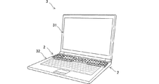
図7は、第1の実施形態で示したスピーカ装置と同様の構造を有するものを備えた第1の実施例に係るノートPCの外観図である。ノートPC3は、16インチワイドディスプレイを備えたディスプレイ側筐体31と、キーボードや各種デバイスが搭載されている本体筐体32と、からなる。ディスプレイ側筐体31と本体筐体32はヒンジにより接続されている。
<Example 1>
FIG. 7 is an external view of the notebook PC according to the first example provided with the same structure as the speaker device shown in the first embodiment. The notebook PC 3 includes a display-
2つのスピーカ装置2は、本体筐体32に設置されており、キーボードの上方に配置されている。2つのスピーカ装置2は、それぞれのスピーカユニットが本体筐体32の外側(右端および左端)に配置されており、できるだけ放音位置が離れ、ステレオスピーカとしての効果が得られるようになっている。また、2つのスピーカ装置2は、それぞれパンチングメタルで覆われている。パンチングメタルは、直径0.5mm、ピッチ1mm、厚さ0.5mmの60度千鳥格子配列の開口率22.5%であり、一般的なノートPCで用いられるものである。
The two
第1の実施例のスピーカ装置2は、16インチワイドディスプレイを備えたノートPCで一般的に用いられる定格出力1W、口径20mm、最低共振周波数600Hzのフルレンジスピーカユニットを用いる。この場合、容積が15ccの場合にほぼ平坦な周波数特性が得られたものとして説明する。バスレフポートの共振周波数は、300Hzとする。300Hzから600Hzに至る周波数帯域では、バスレフポートおよびスピーカユニットから放出される音の比率は連続的に変化する。バスレフポートの構造は、第1の実施形態で示したものと同様である。
The
この様な非常に小型のスピーカ装置では、バスレフポートの内径が極端に細くなり(例えば3〜3.5mm程度となる。)、バスレフポート内の気流抵抗は増大する。したがって、従来の一般的なバスレフポートを用いた場合では、流速が著しく増大し、バスレフポートの効果が低下する。しかし、本実施例1のスピーカ装置の構造であれば、極めて内径が細い部分はポートのほんの一部であり、バスレフポート全体としての気流抵抗は低く抑えられるため、バスレフポートの効果が低下し難い特性を有する。 In such a very small speaker device, the inner diameter of the bass reflex port becomes extremely thin (for example, about 3 to 3.5 mm), and the airflow resistance in the bass reflex port increases. Therefore, when the conventional general bass reflex port is used, the flow velocity is remarkably increased, and the effect of the bass reflex port is lowered. However, in the structure of the speaker device according to the first embodiment, the portion with the extremely small inner diameter is only a part of the port, and the airflow resistance of the entire bass reflex port can be kept low, so that the effect of the bass reflex port is hardly lowered. Has characteristics.
図5(B)は、定格出力1W、口径20mm、最低共振周波数600Hzのフルレンジスピーカユニットを用い、キャビネット容積が15ccである場合の入力電力に対するバスレフ共振周波数における再生音圧を示す図である。同図のグラフの横軸は入力電力(W)であり、縦軸は音圧(dBSPL/m)を示している。本実施例1のバスレフスピーカの1W入力時の音圧を通るように、入力電圧が2倍になると出力音圧が2倍になる3dB/octの傾斜を持った理論値の点線を引くと、本実施例1のバスレフスピーカのグラフとほとんど重なり、本実施例1のバスレフ動作は理想的な入出力直線性を有していることが分かる。 FIG. 5B is a diagram showing a reproduced sound pressure at a bass reflex resonance frequency with respect to input power when a full-range speaker unit having a rated output of 1 W, a diameter of 20 mm, and a minimum resonance frequency of 600 Hz is used and the cabinet volume is 15 cc. The horizontal axis of the graph in the figure is the input power (W), and the vertical axis indicates the sound pressure (dBSPL / m). In order to pass the sound pressure at the time of 1 W input of the bass reflex speaker of Example 1, when the input voltage is doubled, the output sound pressure is doubled, and the dotted line of the theoretical value having a slope of 3 dB / oct is drawn. It almost overlaps with the graph of the bass reflex speaker of the first embodiment, and it can be seen that the bass reflex operation of the first embodiment has ideal input / output linearity.
一方で、従来のような単純な円筒バスレフポートは、図中の四角プロットの様に、入力電力が大きくなるにつれて音圧上昇が3dB/octの理論値よりも小さくなり、入力電圧が増えるほどバスレフポートの効果が得られ難くなって入出力直線性が劣化してしまうことが分かる。 On the other hand, a simple cylindrical bass reflex port as in the prior art has a sound pressure increase smaller than the theoretical value of 3 dB / oct as the input power increases, as shown in the square plot in the figure, and the bass reflex port increases as the input voltage increases. It can be seen that the port effect is difficult to obtain and the input / output linearity deteriorates.
また、この様なノートPCに設けられたスピーカ装置では、聴取者は、スピーカ装置に非常に近い位置(例えば600mm離れた位置)で音を聴取することになる。当然、バスレフポートにも定位感が生じ、従来の一般的なバスレフポートを用いた場合ではスピーカユニットとバスレフポートとを別の位置の音源として認識することになってしまう。 Further, in the speaker device provided in such a notebook PC, the listener listens to the sound at a position very close to the speaker device (for example, a position separated by 600 mm). Of course, the bass reflex port also has a sense of orientation, and when a conventional general bass reflex port is used, the speaker unit and the bass reflex port are recognized as sound sources at different positions.
しかし、この例では、スピーカユニットの中心位置とバスレフポートの外部開口部の中心位置との距離は16.5mmとし、スピーカユニットの直径以下となっている。この場合、600mm離れた聴取者の位置において、スピーカユニットとバスレフポート10の放出した音の到達時間差(位相差に相当する。)は、0.66μsec程度となる。したがって、人が定位感を得る最小閾値の6μsec程度よりもはるかに短く、ほぼ一つの点音源として認識することができる。
However, in this example, the distance between the center position of the speaker unit and the center position of the external opening of the bass reflex port is 16.5 mm, which is smaller than the diameter of the speaker unit. In this case, the arrival time difference (corresponding to the phase difference) of the sound emitted from the speaker unit and the
また、第1の実施形態と同様に、バスレフポートからは空気流がほとんど発生しないため、開口率22.5%のパンチングメタルを設置したとしてもバスレフポートの効果に影響はない。さらに、上述の様なパンチングメタルでは、スピーカユニットが視認されることを防止することができ、デザイン上の優位性も高くなる。 Further, as in the first embodiment, since an air flow is hardly generated from the bass reflex port, even if a punching metal having an aperture ratio of 22.5% is installed, the effect of the bass reflex port is not affected. Furthermore, with the punching metal as described above, the speaker unit can be prevented from being visually recognized, and the superiority in design is enhanced.
〈〈実施例2〉〉
図8は、本発明のスピーカ装置を備えた第2の実施例に係るデスクトップPCの外観図である。デスクトップPC4は、20インチワイドディスプレイや各種デバイスが搭載されている本体筐体41からなる。
<Example 2>
FIG. 8 is an external view of a desktop PC according to the second embodiment provided with the speaker device of the present invention. The
2つのスピーカ装置1は、本体筐体に設置されており、ディスプレイの下方に配置されている。2つのスピーカ装置1は、それぞれのスピーカユニットが本体筐体の外側(右端および左端)に配置されており、できるだけ放音位置が離れ、ステレオスピーカとしての効果が得られるようになっている。また、2つのスピーカ装置1は、それぞれパンチングメタルで覆われている。パンチングメタルは、第1の実施例と同様に、直径0.5mm、ピッチ1mm、厚さ0.5mmの60度千鳥格子配列の開口率22.5%であり、一般的なノートPCで用いられるものである。
The two
第2の実施例のスピーカ装置1は、第1の実施形態で示した定格出力2W、口径30mm、最低共振周波数300Hzのフルレンジスピーカユニットを用い、容積が80ccの場合にほぼ平坦な周波数特性が得られたものとする。バスレフポートの共振周波数は、150Hzとする。150Hzから300Hzに至る周波数帯域では、バスレフポートおよびスピーカユニットから放出される音の比率は連続的に変化する。第1の実施形態でも述べたとおり、スピーカユニットの中心位置とバスレフポートの外部開口部の中心位置との距離は23.5mmとし、スピーカユニットの直径以下となっている。この場合、750mm離れた聴取者の位置において、スピーカユニットとバスレフポート10の放出した音の到達時間差(位相差に相当する。)は、1.15μsec程度となる。したがって、人が定位感を得る最小閾値の6μsec程度よりもはるかに短く、ほぼ一つの点音源として認識することができる。
The
〈〈実施例3〉〉
図9は、本発明のスピーカ装置を備えた第3の実施例に係るテレビの外観図である。同図に示すテレビ5は、32インチワイドディスプレイや各種デバイスが搭載されている本体筐体51からなる。
<Example 3>
FIG. 9 is an external view of a television according to a third embodiment provided with the speaker device of the present invention. The
2つのスピーカ装置7は、本体筐体51に設置されており、ディスプレイの下方に配置されている。2つのスピーカ装置7は、それぞれのスピーカユニットが本体筐体51の外側(右端および左端)に配置されており、できるだけ放音位置が離れ、ステレオスピーカとしての効果が得られるようになっている。また、2つのスピーカ装置7は、それぞれパンチングメタルで覆われている。パンチングメタルは、第1の実施例や第2の実施例と同様に、直径0.5mm、ピッチ1mm、厚さ0.5mmの60度千鳥格子配列の開口率22.5%であり、一般的なノートPCで用いられるものである。
The two speaker devices 7 are installed in the
第3の実施例のスピーカ装置7は、定格出力10W、口径50mm、最低共振周波数200Hzのフルレンジスピーカユニットを用い、容積が450ccの場合にほぼ平坦な周波数特性が得られたものとする。バスレフポートの共振周波数は、100Hzとする。100Hzから200Hzに至る周波数帯域では、バスレフポートおよびスピーカユニットから放出される音の比率は連続的に変化する。スピーカユニットの中心位置とバスレフポートの外部開口部の中心位置との距離は47.0mmとし、スピーカユニットの直径以下となっている。この場合、1200mm離れた聴取者の位置において、スピーカユニットとバスレフポートの放出した音の到達時間差(位相差に相当する。)は、2.7μsec程度となる。したがって、人が定位感を得る最小閾値の6μsec程度よりもはるかに短く、ほぼ一つの点音源として認識することができる。 The speaker device 7 of the third embodiment uses a full-range speaker unit with a rated output of 10 W, an aperture of 50 mm, and a minimum resonance frequency of 200 Hz, and a substantially flat frequency characteristic is obtained when the volume is 450 cc. The resonant frequency of the bass reflex port is 100 Hz. In the frequency band from 100 Hz to 200 Hz, the ratio of the sound emitted from the bass reflex port and the speaker unit changes continuously. The distance between the center position of the speaker unit and the center position of the external opening of the bass reflex port is 47.0 mm, which is smaller than the diameter of the speaker unit. In this case, the arrival time difference (corresponding to the phase difference) between the sound emitted from the speaker unit and the bass reflex port is about 2.7 μsec at the position of the listener 1200 mm away. Therefore, it is much shorter than the minimum threshold of about 6 μsec at which a person has a sense of localization, and can be recognized as almost one point sound source.
〈〈実施例4〉〉
図10は、本発明のスピーカ装置を備えた第4の実施例に係るマイクスピーカ8の外観図である。マイクスピーカは、パンチングメタルの内部にスピーカ装置2とマイク9が配置されており、ノートPCのディスプレイ側筐体の上部に載せて使用するUSB接続型のマイクスピーカである。
<Example 4>
FIG. 10 is an external view of a
第4の実施例に係るマイクスピーカ8において、2つのスピーカ装置2は、第1の実施例と同じものを用いる。第1の実施例とは、スピーカ装置2がディスプレイの下方に設けられているか、ディスプレイ側筐体の上部に載せられているか、の違いである。したがって、聴取者位置においてスピーカユニットとバスレフポートから放出される音の到達時間差は第1の実施例と略同じになり、スピーカユニットとバスレフポートは、ほぼ一つの点音源として認識することができる。
In the
ここで、第4の実施例に係るマイクスピーカ8は、図11(A)に示すように、機能的にエコーキャンセラ27を内蔵している。エコーキャンセラ27には、帰還音響系の伝達関数を模擬する適応型フィルタ271が用いられる。適応型フィルタ271は、スピーカ装置2からマイク9に至る帰還音響系の伝達関数を模擬し、スピーカ装置2に供給する音声信号をフィルタ処理することにより擬似エコー成分を生成する。そして、生成した擬似エコー成分をマイク9で取得した音声信号から除去する。適応型フィルタ271は、擬似エコー成分を除去した後の残差音声信号を入力し、この残差音声信号がゼロまたは小さくなるようにフィルタ係数を自動更新する(帰還音響系の伝達関数に一致するようにフィルタ係数を更新する)。仮に、スピーカユニットとバスレフポートが離れた位置に存在したり、スピーカユニットとバスレフポートの音の放射方向が異なったりすると、音源が移動したり、音源が1つから複数(あるいは複数から1つ)に変化したりするため、帰還音響系の伝達関数が頻繁に変化することになる。したがって、適応型フィルタが正確に伝達関数の推定ができなくなり、エコーキャンセル効果が低下する。しかし、第4の実施例に係るマイクスピーカは、ほぼ1つの点音源として定位することになるため、正確な伝達関数の推定を行うことができる。なお、適応型フィルタは、スピーカ装置毎に設けてもよいし、2つのスピーカ装置に共通のものを1つ設ける態様であってもよい。いずれにしても音源が移動することはないため、正確な伝達関数の推定を行うことができる。
Here, the
〈〈応用例〉〉
図11(B)は、応用例に係る点音源シミュレーションシステムの構成を示すブロック図である。この点音源シミュレーションシステムは、第1〜第4の実施例で示したいずれかのスピーカ装置(同図中においてはスピーカ装置2)と、スピーカ装置に音声信号を供給する信号処理装置6と、を備えている。
<Application example>
FIG. 11B is a block diagram illustrating a configuration of a point sound source simulation system according to an application example. This point sound source simulation system includes any one of the speaker devices shown in the first to fourth embodiments (
信号処理装置6は、仮想点音源位置から聴取者に至る伝達関数(頭部伝達関数)を音声信号に付与し、バーチャルサラウンドを実現するものである。信号処理装置6は、AVアンプ等の単体製品として実現される態様や、ソフトウェアとして上述のノートPC等に搭載される態様も可能である。
The
人は、左右の耳に到達する音声の音量差や時間差と共に、頭部と耳介による周波数スペクトルの形状変化によっても定位感を得ており、信号処理装置6は、モノーラル信号に対して、ある仮想点音源の位置から左右の耳に至る伝達関数(頭部伝達関数)を付与し、左耳位置において聴取される信号と右耳位置において聴取されるバイノーラル信号を作り出す。これを左右の耳にそれぞれ提示することで、仮想点音源の位置に音像が定位していると知覚させることができる。
A person has a sense of localization due to a change in the frequency spectrum of the head and pinna as well as a volume difference and a time difference between voices reaching the left and right ears, and the
ここで、仮想点音源の位置に正確に音像を定位させるには、まず第1に左右のスピーカ装置から同時に同じ音圧で音が届く場所、すなわち、2つのスピーカ装置と等距離にある線上で聴取する必要がある。しかし、この場所においても、左右2つのスピーカ装置と左右の耳に至る音響伝達経路には、最少でも図11(B)に示すように4つの直接経路が存在し、左のスピーカから発せられた音はまず左耳に到達するが、時間遅れを持って右耳にも到達する。同様に右のスピーカから発せられた音もまた両耳に届くため、両耳間のクロストークが発生し、正確な音像定位が得られ難いことになる。したがって、信号処理装置6は、バイノーラル化した信号にさらにクローストークを打ち消すためのクロストークキャンセル処理を行う。
Here, in order to accurately localize the sound image at the position of the virtual point sound source, first of all, in a place where the sound reaches from the left and right speaker devices simultaneously with the same sound pressure, that is, on a line equidistant from the two speaker devices. It is necessary to listen. However, even in this place, there are at least four direct paths in the sound transmission path from the left and right speaker devices to the left and right ears as shown in FIG. The sound first reaches the left ear, but also reaches the right ear with a time delay. Similarly, since the sound emitted from the right speaker also reaches both ears, crosstalk between both ears occurs, and accurate sound image localization is difficult to obtain. Therefore, the
例えば、左側のスピーカ装置から放出され、右耳に至るクロストークの逆位相の成分を右側のスピーカ装置から放出し右耳の位置で音圧を打ち消すことにより、左側のスピーカ装置の音が右耳に聞こえるのを抑制する。逆に、右側のスピーカ装置から放出され、左耳に至るクロストークの逆位相の成分を左側のスピーカ装置から放出し左耳の位置で音圧を打ち消すことにより、右側のスピーカ装置の音が左耳に聞こえるのを抑制する。逆位相の音は、左右のスピーカ装置の位置を仮想点音源位置として、左右の耳に至る音の時間差と音量差をシミュレーションすることにより得られる。また、クロストークの一部は顔で回折することによってスペクトルが変化するため、より効果的なクロストークキャンセルを行なうためには頭部伝達関数を用いたシミュレーションが行なわれる。第1の実施例〜第4の実施例で示したスピーカ装置の使用用途は、パーソナルユーズが主体であり、特にコンピュータにおいては使用者の耳の位置をほぼ特定する事が可能なため、精緻なシミュレーションによって効果的なサラウンド効果が期待できる。 For example, the sound of the left speaker device is emitted from the left speaker device by canceling the sound pressure at the position of the right ear by emitting the component of the opposite phase of the crosstalk that is emitted from the left speaker device and reaches the right ear. To suppress the sound. On the contrary, the sound of the right speaker device is emitted from the left speaker device by canceling the sound pressure at the position of the left ear by emitting the opposite phase component of the crosstalk that is emitted from the right speaker device and reaches the left ear. Suppresses hearing. The sound of opposite phase is obtained by simulating the time difference and the volume difference of the sound reaching the left and right ears using the positions of the left and right speaker devices as virtual point sound source positions. In addition, since a spectrum is changed by diffracting part of the crosstalk by the face, a simulation using a head-related transfer function is performed in order to perform more effective crosstalk cancellation. The usage of the speaker device shown in the first to fourth embodiments is mainly personal use, and in particular, in a computer, it is possible to almost specify the position of the user's ear, so it is precise. An effective surround effect can be expected by simulation.
従来の一般的なバスレフポートのスピーカを用いた場合では、スピーカユニットとバスレフポートとを別の位置の音源として認識することになってしまうため、放出する音の帯域によって音源位置が変化してしまう。また、スピーカユニットとバスレフポートの音の放射方向が異なる場合、クロストークは直接経路以外にも反射を伴った間接経路でも生ずることになる。したがって、点音源を前提としたシミュレーションとの誤差が大きくなり打ち消し効果が低下してしまい、クロストークキャンセルの特性が劣化してしまう。 When a conventional general bass reflex port speaker is used, the speaker unit and the bass reflex port are recognized as sound sources at different positions, so the sound source position changes depending on the band of the sound to be emitted. . Further, when the sound emission directions of the speaker unit and the bass reflex port are different, the crosstalk occurs not only in the direct route but also in the indirect route with reflection. Therefore, an error from a simulation based on a point sound source is increased, the cancellation effect is reduced, and the characteristics of the crosstalk cancellation are deteriorated.
しかし、上記第1の実施例〜第4の実施例で示したスピーカ装置であれば、スピーカユニットとバスレフポートからの音は、ほぼ一つの点音源として認識することができ、かつスピーカユニットとバスレフポートの音の放出方向が揃っているためクロストーク経路は直接経路が主体となるため、シミュレーションとの誤差はほとんどなく、クロストークキャンセルの効果を最大限に発揮し、効果的なバーチャルサラウンドの効果を提供することができる。 However, in the speaker devices shown in the first to fourth embodiments, the sound from the speaker unit and the bass reflex port can be recognized as almost one point sound source, and the speaker unit and the bass reflex device are recognized. Since the sound emission direction of the ports is aligned, the crosstalk route is mainly a direct route, so there is almost no error with the simulation, the effect of crosstalk cancellation is maximized, and the effect of effective virtual surround Can be provided.
1…スピーカ装置
10…バスレフポート
11…キャビネット
12…前面板
13…背面板
14…天面板
15…底面板
16A…側面板
16B…側面板
17…外部開口部
18…内部開口部
DESCRIPTION OF
Claims (5)
前記バスレフポートは、開口部から該バスレフポートの内部に向かう軸方向に沿って中空断面積が徐々に小さくなる管状体を有し、当該管状体は、中空断面の一方向の長さが前記軸方向に沿って変化しない一定寸法からなり、
前記バスレフポートのエンクロージャ内部側の開口部は、該バスレフポートを挟んで前記スピーカユニットと反対側に設けられ、
前記スピーカユニットの中心位置と前記エンクロージャ外部側の開口部の中心位置との距離は、前記スピーカユニットの直径以下であることを特徴とするスピーカ装置。 A speaker device comprising a phase reversal type enclosure in which a speaker unit and a bass reflex port are installed,
The bass reflex port has a tubular body having a hollow cross-sectional area that gradually decreases along an axial direction from the opening toward the inside of the bass reflex port. It consists of a fixed dimension that does not change along the direction,
The opening inside the enclosure of the bass reflex port is provided on the opposite side of the speaker unit across the bass reflex port ,
The distance between the center position of the speaker unit and the center position of the opening outside the enclosure is not more than the diameter of the speaker unit.
前記バスレフポートのエンクロージャ外部側の開口部は、前記スピーカユニットの音波放出方向と同一の方向に設けられていることを特徴とする請求項1に記載のスピーカ装置。 The bass reflex port is installed such that the axial direction is orthogonal to the sound wave emitting direction of the speaker unit,
The speaker device according to claim 1, wherein the opening of the bass reflex port on the outside of the enclosure is provided in the same direction as the sound wave emission direction of the speaker unit.
前記スピーカ装置に音声信号を供給する信号処理装置と、
を備え、
前記信号処理装置は、仮想音源位置から聴取者に至る伝達関数を前記音声信号に付与することを特徴とする音源シミュレーションシステム。 The speaker device according to any one of claims 1 to 3 ,
A signal processing device for supplying an audio signal to the speaker device;
With
The sound signal simulation system, wherein the signal processing device adds a transfer function from a virtual sound source position to a listener to the audio signal.
音声信号を取得するマイクと、
前記スピーカ装置から前記マイクに至る伝達関数を模擬し、前記スピーカに供給する音声信号をフィルタ処理することにより擬似エコー成分を生成し、生成した擬似エコー成分を前記マイクで取得した音声信号から除去するエコーキャンセラと、
を備えたエコーキャンセルシステム。 The speaker device according to any one of claims 1 to 3 ,
A microphone to acquire the audio signal;
Simulate the transfer function from the speaker device to the microphone, filter the audio signal supplied to the speaker, generate a pseudo echo component, and remove the generated pseudo echo component from the audio signal acquired by the microphone Echo canceller,
Echo cancellation system with
Priority Applications (5)
| Application Number | Priority Date | Filing Date | Title |
|---|---|---|---|
| JP2010126391A JP5002787B2 (en) | 2010-06-02 | 2010-06-02 | Speaker device, sound source simulation system, and echo cancellation system |
| CN201180027368.1A CN102918870B (en) | 2010-06-02 | 2011-05-31 | Speaker device, sound source simulation system, and echo canceling system |
| EP11789836.1A EP2579612A4 (en) | 2010-06-02 | 2011-05-31 | Speaker device, sound source simulation system, and echo canceling system |
| PCT/JP2011/062552 WO2011152433A1 (en) | 2010-06-02 | 2011-05-31 | Speaker device, sound source simulation system, and echo canceling system |
| US13/701,780 US8938084B2 (en) | 2010-06-02 | 2011-05-31 | Speaker device, sound source simulation system, and echo cancellation system |
Applications Claiming Priority (1)
| Application Number | Priority Date | Filing Date | Title |
|---|---|---|---|
| JP2010126391A JP5002787B2 (en) | 2010-06-02 | 2010-06-02 | Speaker device, sound source simulation system, and echo cancellation system |
Publications (3)
| Publication Number | Publication Date |
|---|---|
| JP2011254272A JP2011254272A (en) | 2011-12-15 |
| JP2011254272A5 JP2011254272A5 (en) | 2012-05-17 |
| JP5002787B2 true JP5002787B2 (en) | 2012-08-15 |
Family
ID=45066793
Family Applications (1)
| Application Number | Title | Priority Date | Filing Date |
|---|---|---|---|
| JP2010126391A Active JP5002787B2 (en) | 2010-06-02 | 2010-06-02 | Speaker device, sound source simulation system, and echo cancellation system |
Country Status (5)
| Country | Link |
|---|---|
| US (1) | US8938084B2 (en) |
| EP (1) | EP2579612A4 (en) |
| JP (1) | JP5002787B2 (en) |
| CN (1) | CN102918870B (en) |
| WO (1) | WO2011152433A1 (en) |
Families Citing this family (14)
| Publication number | Priority date | Publication date | Assignee | Title |
|---|---|---|---|---|
| US9655001B2 (en) * | 2015-09-24 | 2017-05-16 | Cisco Technology, Inc. | Cross mute for native radio channels |
| CN108353241B (en) * | 2015-09-25 | 2020-11-06 | 弗劳恩霍夫应用研究促进协会 | Rendering system |
| US10547942B2 (en) | 2015-12-28 | 2020-01-28 | Samsung Electronics Co., Ltd. | Control of electrodynamic speaker driver using a low-order non-linear model |
| WO2017186311A1 (en) * | 2016-04-29 | 2017-11-02 | Burmester Audiosysteme Gmbh | Bass reflex tube for a loudspeaker |
| JP6812706B2 (en) * | 2016-08-31 | 2021-01-13 | ヤマハ株式会社 | Speaker system |
| JP6277314B1 (en) * | 2017-08-07 | 2018-02-07 | 勝巳 瀬戸 | Speaker device |
| US10506347B2 (en) | 2018-01-17 | 2019-12-10 | Samsung Electronics Co., Ltd. | Nonlinear control of vented box or passive radiator loudspeaker systems |
| US10701485B2 (en) | 2018-03-08 | 2020-06-30 | Samsung Electronics Co., Ltd. | Energy limiter for loudspeaker protection |
| EP3547713B1 (en) | 2018-03-27 | 2023-11-22 | Sony Group Corporation | Loudspeaker with an acoustic waveguide, and method |
| US11012788B2 (en) | 2018-03-27 | 2021-05-18 | Sony Corporation | Loudspeaker system |
| US11012773B2 (en) | 2018-09-04 | 2021-05-18 | Samsung Electronics Co., Ltd. | Waveguide for smooth off-axis frequency response |
| US10797666B2 (en) | 2018-09-06 | 2020-10-06 | Samsung Electronics Co., Ltd. | Port velocity limiter for vented box loudspeakers |
| US20210027002A1 (en) * | 2019-07-25 | 2021-01-28 | Samsung Electronics Co., Ltd. | Low noise port tube |
| US11356773B2 (en) | 2020-10-30 | 2022-06-07 | Samsung Electronics, Co., Ltd. | Nonlinear control of a loudspeaker with a neural network |
Family Cites Families (15)
| Publication number | Priority date | Publication date | Assignee | Title |
|---|---|---|---|---|
| JPH01254096A (en) * | 1988-04-04 | 1989-10-11 | Yamaha Corp | Acoustic equipment |
| US4974698A (en) * | 1989-10-11 | 1990-12-04 | Oakwood Metal Fabricating Company | Speaker cover grille installation |
| JPH0712194Y2 (en) * | 1990-04-11 | 1995-03-22 | 株式会社本田ロック | Vehicle steering lock device |
| US5892183A (en) * | 1997-07-26 | 1999-04-06 | U.S. Philips Corporation | Loudspeaker system having a bass-reflex port |
| CN1179602C (en) | 1999-03-03 | 2004-12-08 | 音响株式会社 | Speaker system |
| US6307947B1 (en) * | 2000-03-01 | 2001-10-23 | David Wiener | Low profile speaker enclosure |
| US7711134B2 (en) * | 2001-06-25 | 2010-05-04 | Harman International Industries, Incorporated | Speaker port system for reducing boundary layer separation |
| JP4063269B2 (en) * | 2004-10-29 | 2008-03-19 | ヤマハ株式会社 | Audio amplifier and audio system |
| US20080273716A1 (en) * | 2005-09-27 | 2008-11-06 | Kosuke Saito | Feedback Sound Eliminating Apparatus |
| JP4059272B2 (en) * | 2006-01-18 | 2008-03-12 | ヤマハ株式会社 | Speaker system and speaker enclosure |
| JP4946261B2 (en) | 2006-08-16 | 2012-06-06 | ソニー株式会社 | Speaker device |
| JP3129553U (en) | 2006-11-08 | 2007-03-01 | 純 杉原 | Corner duct type, point sound source double bass reflex speaker |
| JP4366614B2 (en) * | 2007-08-24 | 2009-11-18 | ソニー株式会社 | Speaker system and fitting device |
| JP5110012B2 (en) * | 2008-03-27 | 2012-12-26 | ヤマハ株式会社 | Speaker device |
| US8391528B2 (en) * | 2008-07-22 | 2013-03-05 | Freedman Electronics Pty Ltd | Loudspeaker slotted duct port |
-
2010
- 2010-06-02 JP JP2010126391A patent/JP5002787B2/en active Active
-
2011
- 2011-05-31 WO PCT/JP2011/062552 patent/WO2011152433A1/en active Application Filing
- 2011-05-31 US US13/701,780 patent/US8938084B2/en active Active
- 2011-05-31 EP EP11789836.1A patent/EP2579612A4/en not_active Ceased
- 2011-05-31 CN CN201180027368.1A patent/CN102918870B/en active Active
Also Published As
| Publication number | Publication date |
|---|---|
| EP2579612A4 (en) | 2014-08-27 |
| US20130083937A1 (en) | 2013-04-04 |
| CN102918870B (en) | 2014-07-16 |
| EP2579612A1 (en) | 2013-04-10 |
| CN102918870A (en) | 2013-02-06 |
| US8938084B2 (en) | 2015-01-20 |
| WO2011152433A1 (en) | 2011-12-08 |
| JP2011254272A (en) | 2011-12-15 |
Similar Documents
| Publication | Publication Date | Title |
|---|---|---|
| JP5002787B2 (en) | Speaker device, sound source simulation system, and echo cancellation system | |
| US11575985B2 (en) | Mass loaded earbud with vent chamber | |
| JP4953490B1 (en) | Twin Driver Earphone | |
| US8737664B2 (en) | In-the-ear porting structures for earbud | |
| US20080159554A1 (en) | Noise reduction device and method thereof | |
| US20110064238A1 (en) | Microphone/speaker device | |
| CN113163297B (en) | Audio device and intelligent head-mounted equipment | |
| CN113242485B (en) | In-ear earphone | |
| WO2023030111A1 (en) | Open-field far-field silencing speaker apparatus, head-mounted device and signal processing method | |
| US20170251297A1 (en) | In-Ear Earphone | |
| CN112584265A (en) | Earphone set | |
| JP5872722B1 (en) | Earphone with communication pipe | |
| CN206908842U (en) | sound-producing device | |
| JP3154917U (en) | Bass reflex speaker duct | |
| RU2621362C1 (en) | Inter-channel headphone | |
| JP2015080183A (en) | Earphone having howling prevention structure | |
| KR102167470B1 (en) | Opened air type earphone with bracket forming bass pipe | |
| CN220985818U (en) | Earphone | |
| CN212727417U (en) | Sound production structure, audio equipment and wear display device | |
| CN210579081U (en) | Sound box | |
| WO2024077647A1 (en) | Acoustic apparatus | |
| JP2009164942A (en) | Headphone | |
| TWM517497U (en) | Speaker unit and earphone | |
| TWI455608B (en) | Headphone with acoustic regulating device | |
| JP2016201786A (en) | Earphone with communicating tube |
Legal Events
| Date | Code | Title | Description |
|---|---|---|---|
| A621 | Written request for application examination |
Free format text: JAPANESE INTERMEDIATE CODE: A621 Effective date: 20120221 |
|
| A521 | Written amendment |
Free format text: JAPANESE INTERMEDIATE CODE: A523 Effective date: 20120327 |
|
| A871 | Explanation of circumstances concerning accelerated examination |
Free format text: JAPANESE INTERMEDIATE CODE: A871 Effective date: 20120327 |
|
| TRDD | Decision of grant or rejection written | ||
| A975 | Report on accelerated examination |
Free format text: JAPANESE INTERMEDIATE CODE: A971005 Effective date: 20120402 |
|
| A01 | Written decision to grant a patent or to grant a registration (utility model) |
Free format text: JAPANESE INTERMEDIATE CODE: A01 Effective date: 20120410 |
|
| A01 | Written decision to grant a patent or to grant a registration (utility model) |
Free format text: JAPANESE INTERMEDIATE CODE: A01 |
|
| A61 | First payment of annual fees (during grant procedure) |
Free format text: JAPANESE INTERMEDIATE CODE: A61 Effective date: 20120423 |
|
| FPAY | Renewal fee payment (event date is renewal date of database) |
Free format text: PAYMENT UNTIL: 20150601 Year of fee payment: 3 |
|
| R150 | Certificate of patent or registration of utility model |
Ref document number: 5002787 Country of ref document: JP Free format text: JAPANESE INTERMEDIATE CODE: R150 Free format text: JAPANESE INTERMEDIATE CODE: R150 |