JP5000982B2 - Laser welding method for differential thickness materials - Google Patents
Laser welding method for differential thickness materials Download PDFInfo
- Publication number
- JP5000982B2 JP5000982B2 JP2006296510A JP2006296510A JP5000982B2 JP 5000982 B2 JP5000982 B2 JP 5000982B2 JP 2006296510 A JP2006296510 A JP 2006296510A JP 2006296510 A JP2006296510 A JP 2006296510A JP 5000982 B2 JP5000982 B2 JP 5000982B2
- Authority
- JP
- Japan
- Prior art keywords
- thin plate
- welding
- plate
- laser
- bead
- Prior art date
- Legal status (The legal status is an assumption and is not a legal conclusion. Google has not performed a legal analysis and makes no representation as to the accuracy of the status listed.)
- Expired - Fee Related
Links
Images


Description
本発明は、板厚が異なる平板状の厚板と薄板とを突合わせ、両者の突合わせ面をレーザ溶接によって接合するのに好適に用いられる差厚材のレーザ溶接方法に関する。 The present invention relates to a laser welding method for a differential thickness material that is preferably used for abutting flat plate-like thick plates and thin plates having different plate thicknesses and joining the abutting surfaces thereof by laser welding.
一般に、板厚が異なる平板状の厚板と薄板とを突合わせて溶接する場合には、厚板と薄板との突合わせ面に生じた凹凸部(ギャップ)を埋めながら両者を溶接するため、フィラワイヤ等の溶加材を溶融させつつ、厚板と薄板との突合わせ面に沿ってレーザ溶接を行なう溶接方法が採用されている。 In general, when welding a flat plate and a thin plate with different plate thicknesses butted together, in order to weld both while filling the uneven part (gap) generated on the butted surface of the thick plate and thin plate, A welding method is employed in which laser welding is performed along the abutting surface between a thick plate and a thin plate while melting a filler material such as a filler wire.
ここで、厚板と薄板との突合わせ面のギャップは、厚板や薄板に対して切断加工等を行ったときのバリ、厚板や薄板を溶断したときの酸化膜等によって発生するもので、当該ギャップ内に溶加材を溶融させて充填することにより、溶接強度の低下を招くアンダフィル等がない良好な溶接ビードを形成する必要がある。 Here, the gap between the abutting surfaces of the thick plate and the thin plate is caused by burrs when the thick plate or thin plate is cut, an oxide film when the thick plate or thin plate is melted, or the like. It is necessary to form a good weld bead free from underfill or the like that causes a decrease in weld strength by melting and filling the filler material in the gap.
しかしながら、厚板と薄板との突合わせ面に生じるギャップの大きさは一定ではないため、例えば最も大きなギャップに合わせて溶加材の添加量を設定すると、厚板と薄板との突合わせ面のうちギャップが小さい部位では溶加材の添加量が過剰となる。この結果、薄板側のビード止端部が、薄板に向けて凸状に張出すようになり、薄板側のビード止端部と薄板の表面(上面)との間に急激な段差が形成されてしまう。 However, since the size of the gap generated on the abutting surface between the thick plate and the thin plate is not constant, for example, if the amount of filler added is set in accordance with the largest gap, the abutting surface between the thick plate and the thin plate Of these, the amount of filler material added is excessive at the site where the gap is small. As a result, the bead toe portion on the thin plate side protrudes in a convex shape toward the thin plate, and a steep step is formed between the bead toe portion on the thin plate side and the surface (upper surface) of the thin plate. End up.
このように、薄板側のビード止端部と薄板の表面との間に段差が形成された場合には、溶接構造体に繰返して荷重が作用することにより薄板側のビード止端部に応力が集中してしまう。この結果、薄板側のビード止端部が起点となって亀裂(クラック)が発生し、溶接構造体が破損してしまうという問題がある。 As described above, when a step is formed between the bead toe portion on the thin plate side and the surface of the thin plate, stress is applied to the bead toe portion on the thin plate side by repeatedly applying a load to the welded structure. Concentrate. As a result, there is a problem that a crack (crack) is generated starting from the bead toe portion on the thin plate side, and the welded structure is damaged.
これに対し、2枚の金属板を溶加材を用いて溶接してなる溶接継手において、各金属板間に形成された溶接ビードの止端部を、TIG溶接等の加熱手段によって再溶融させることにより、ビード止端部を金属板の表面から滑らかに連続するように形成し、このビード止端部に応力が集中するのを抑えるようにした溶接継手の製造方法が提案されている(例えば、特許文献1参照)。 In contrast, in a welded joint formed by welding two metal plates using a filler metal, the toe portion of the weld bead formed between the metal plates is remelted by a heating means such as TIG welding. Thus, a method for manufacturing a welded joint has been proposed in which the bead toe is formed so as to be smoothly continuous from the surface of the metal plate, and stress is prevented from concentrating on the bead toe (for example, , See Patent Document 1).
また、他の従来技術として、2枚の金属板間に形成された溶接ビードの止端部に回転体を押圧し、この回転体によってビード止端部を加圧することにより、このビード止端部に応力が集中するのを抑えるようにした溶接止端部の加圧方法が提案されている(例えば、特許文献2参照)。 Further, as another prior art, the bead toe portion is formed by pressing a rotating body against the toe end portion of a weld bead formed between two metal plates and pressurizing the bead toe end portion with the rotating body. There has been proposed a method for pressurizing the weld toe so as to suppress the concentration of stress on the surface (for example, see Patent Document 2).
しかし、上述した特許文献1のTIG溶接による溶接継手の製造方法は、ほぼ等しい板厚を有する2枚の金属板を溶接するには適しているが、板厚が異なる厚板と薄板との突合わせ面を溶接する場合には、ビード止端部を狙ってアークを発生しても、磁気吹きによりトーチに対してビード止端部より近距離側の板材に向かってアークが曲がるため、TIG溶接によりビード止端部を再溶融することは困難である。
However, although the above-described method for manufacturing a welded joint by TIG welding in
一方、上述した特許文献2の溶接止端部の加圧方法は、溶接ビードの止端部を回転体によって加圧するための加圧装置が必要となり、この加圧装置にかかるコストが増大してしまうという問題がある。
On the other hand, the method for pressurizing the weld toe portion of
本発明は上述した従来技術の問題に鑑みなされたもので、板厚が異なる厚板と薄板との突合わせ面に形成された溶接ビードのうち、薄板側のビード止端部に応力が集中するのを抑え、溶接強度を高めることができるようにした差厚材のレーザ溶接方法を提供することを目的としている。 The present invention has been made in view of the above-described problems of the prior art, and among the weld beads formed on the abutting surfaces of the thick plate and the thin plate having different plate thicknesses, stress is concentrated on the bead toe portion on the thin plate side. It is an object of the present invention to provide a laser welding method for a differential thickness material that can suppress welding and increase welding strength.
上述した課題を解決するため本発明は、板厚が異なる厚板と薄板とを突合わせてレーザ溶接を行なう差厚材のレーザ溶接方法に適用される。 In order to solve the above-described problems, the present invention is applied to a laser welding method for a differential thickness material in which laser welding is performed by abutting a thick plate and a thin plate having different plate thicknesses.
そして、請求項1の発明による溶接方法の特徴は、レーザビームによって溶加材を溶かしながら前記厚板と薄板との突合わせ面にレーザ溶接を施し、前記厚板と薄板との間に溶接ビードを形成する第1の溶接工程と、前記第1の溶接工程によって形成された前記溶接ビードのうち前記薄板側のビード止端部をレーザビームによって再度溶融させる第2の溶接工程とを有し、前記第1の溶接工程では、前記厚板と薄板との突合わせ面に沿って始端位置から終端位置に向けてレーザ溶接を行ない、前記第2の溶接工程では、前記第1の溶接工程における溶接方向の終端位置から始端位置に向けて前記薄板側のビード止端部にレーザビームを照射することにある。
The features of the welding method according to the invention of
請求項2の発明は、前記第2の溶接工程における前記レーザビームの光軸は、ビーム先端の照射面積のうち1/2以上が前記薄板側のビード止端部に照射される範囲に設定したことにある。
In the invention of
請求項3の発明は、前記第2の溶接工程では、前記薄板側のビード止端部に照射するレーザビームの熱量を、前記第1の溶接工程で前記厚板と薄板との突合わせ面に照射したレーザビームの熱量よりも低く設定したことにある。 According to a third aspect of the present invention, in the second welding step, the amount of heat of the laser beam irradiated to the bead toe portion on the thin plate side is applied to the butt surface between the thick plate and the thin plate in the first welding step. That is, it is set lower than the amount of heat of the irradiated laser beam.
請求項1の発明によれば、溶加材を用いた第1の溶接工程において、厚板と薄板との突合わせ面に形成された溶接ビードのうち薄板側のビード止端部が、薄板の表面との間に段差を形成したとしても、第2の溶接工程において、薄板側のビード止端部をレーザビームによって再度溶融させることにより、ビード止端部と薄板の表面との間の段差をなくし、ビード止端部が薄板の表面に滑らかに連続するように成形することができる。 According to the first aspect of the present invention, in the first welding step using the filler metal, the bead toe portion on the thin plate side of the weld bead formed on the abutting surface of the thick plate and the thin plate is made of a thin plate. Even if a step is formed between the surface and the surface of the thin plate, in the second welding step, the bead toe portion on the thin plate side is melted again by the laser beam, thereby forming a step between the bead toe portion and the surface of the thin plate. Alternatively, the bead toe can be formed so as to be smoothly continuous with the surface of the thin plate.
これにより、薄板側のビード止端部に応力が集中するのを抑え、差厚材の溶接強度を高めることができる。しかも、第1の溶接工程における溶加材を用いた厚板と薄板との溶接と、第2の溶接工程における薄板側のビード止端部の再溶融とを、いずれもレーザ溶接によって行なうことができるので、例えば第1,第2の溶接工程を単一のレーザ溶接機を用いて実行することにより、差厚材の製造コストを低減することができる。 Thereby, it can suppress that stress concentrates on the bead toe part by the side of a thin plate, and can improve the welding strength of a thickness difference material. In addition, the welding of the thick plate and the thin plate using the filler material in the first welding step and the remelting of the bead toe portion on the thin plate side in the second welding step can both be performed by laser welding. Therefore, for example, by performing the first and second welding processes using a single laser welding machine, the manufacturing cost of the differential thickness material can be reduced.
ここで、第1の溶接工程で厚板と薄板との突合わせ面をレーザ溶接するときの溶接方向と、第2の溶接工程で薄板側のビード止端部にレーザビームを照射するときの溶接方向とが、互いに逆向きとなる。この場合、レーザ溶接は、溶接作業の始端位置から終端位置に向けてレーザビームを照射することにより、溶融金属を溶接方向の後側(始端位置側)に流しながら終端位置へと進行するので、溶接ビードは、レーザ溶接の始端位置では盛上がり、終端位置では窪むようになる。 Here, the welding direction when laser welding the butted surfaces of the thick plate and the thin plate in the first welding step, and the welding when irradiating the laser beam to the bead toe portion on the thin plate side in the second welding step. The directions are opposite to each other. In this case, laser welding proceeds to the end position while flowing the molten metal to the rear side (start end position side) in the welding direction by irradiating the laser beam from the start end position to the end position of the welding operation. The weld bead rises at the start position of laser welding and becomes depressed at the end position.
これに対し、第1の溶接工程と第2の溶接工程とで溶接方向を反対向きとすることにより、第1の溶接工程における溶接の終端位置が、第2の溶接工程における溶接の始端位置と重なり、第1の溶接工程における溶接の始端位置が、第2の溶接工程における溶接の終端位置と重なる。このため、厚板と薄板との突合わせ面に形成される溶接ビードの形状を、その長さ方向(溶接方向)において均一化することができ、差厚材の溶接強度を一層高めることができる。 On the other hand, by making the welding directions opposite in the first welding process and the second welding process, the end position of welding in the first welding process is the start position of welding in the second welding process. Overlap, the welding start end position in the first welding process overlaps with the welding end position in the second welding process. For this reason, the shape of the weld bead formed on the abutting surface of the thick plate and the thin plate can be made uniform in the length direction (welding direction), and the welding strength of the differential thickness material can be further increased. .
さらに、第1の溶接工程での終端位置が、第2の溶接工程での始端位置となるので、第1の溶接工程と第2の溶接工程とを連続的に実行することができ、厚板と薄板とをレーザ溶接するときの作業性を高めることができる。 Furthermore, since the terminal position in the first welding process is the starting position in the second welding process, the first welding process and the second welding process can be executed continuously, And the workability when laser welding the thin plate.
請求項2の発明によれば、第1の溶接工程で形成された薄板側のビード止端部に対し、ビーム先端の照射面積の1/2以上を照射することにより、薄板側のビード止端部とその周囲に対し、レーザビームを無駄なく照射することができる。これにより、薄板側のビード止端部を効率良く溶融させることができると共に、ビード止端部の周囲を加熱して溶融金属のぬれ性を高めることができる。
According to the invention of
この結果、薄板の表面との間に急激な段差を形成する薄板側のビード止端部を溶融させ、この溶融金属を薄板側へと導くことができるので、ビード止端部の形状を薄板の表面に滑らかに連続させることができ、差厚材の溶接強度を高めることができる。 As a result, the bead toe portion on the thin plate side that forms a steep step with the surface of the thin plate can be melted, and this molten metal can be guided to the thin plate side. It can be made to continue smoothly on the surface, and the welding strength of the differential thickness material can be increased.
請求項3の発明によれば、第2の溶接工程において薄板側のビード止端部に照射するレーザビームの熱量を、第1の溶接工程で厚板と薄板との突合わせ面に照射したレーザビームの熱量よりも低く設定することにより、薄板側のビード止端部が必要以上に溶融してしまうことがなく、溶接歪みや変形等を抑えることができるので、信頼性の高い差厚材を製造することができる。
According to the invention of
以下、本発明に係る差厚材のレーザ溶接方法の実施の形態を、図1ないし図11を参照しつつ詳細に説明する。 Hereinafter, an embodiment of a laser welding method for a differential thickness material according to the present invention will be described in detail with reference to FIGS.
図中、1は金属板からなる厚板を示し、該厚板1は、後述の薄板2と共に差厚材11を構成するものである。ここで、厚板1は、例えば厚肉な金属板をレーザ切断、ガス切断等の手段を用いて切断することにより、厚さ寸法Tを有する長方形の平板状に形成されている。そして、厚板1のうち後述の薄板2と対面する端面は、後述する薄板2の突合わせ面2Aに当接する突合わせ面1Aとなっている。
In the figure, 1 indicates a thick plate made of a metal plate, and the
2は金属板からなる薄板で、該薄板2は、レーザ溶接によって厚板1に突合わせ溶接されるものである。ここで、薄板2は、例えば薄肉な金属板をレーザ切断、ガス切断等の手段を用いて切断することにより、厚板1よりも小さな厚さ寸法tを有する長方形の平板状に形成されている。そして、薄板2のうち厚板1と対面する端面は、厚板材1の突合わせ面1Aに当接する突合わせ面2Aとなっている。
そして、厚板1と薄板2とは、突合わせ面1A,2Aを突合わせた状態で定盤(図示せず)上に配置され、厚板1の突合わせ面1Aの上側は、薄板2の突合わせ面2Aから上方に突出している。また、互いに突合わされた厚板1と薄板2の長手方向の一端側は、後述する第1の溶接工程でレーザ溶接が開始される始端位置3となり、長手方向の他端側は、第1の溶接工程でレーザ溶接が終了する終端位置4となっている。
The
5は厚板1の突合わせ面1Aと薄板2の突合わせ面2Aとが交差する交差部で、この交差部5は、厚板1の突合わせ面1Aと薄板2の突合わせ面2Aとに沿って長手方向に延びている。そして、この交差部5は、後述する溶加材6の先端が突当てられることにより、この溶加材6の先端を案内するものである。
6は厚板1の突合わせ面1Aと薄板2の突合わせ面2Aとの交差部5に供給される溶加材で、該溶加材6は、図2に示すように、フィラワイヤ等と呼ばれる細長い線状の金属材料からなっている。そして、この溶加材6は、溶加材用の供給装置(図示せず)によって厚板1と薄板2との間の交差部5に連続的に供給され、後述するレーザ溶接機7からのレーザビーム8が照射されるものである。
6 is a filler material supplied to the
7はレーザ溶接機で、該レーザ溶接機7は、レーザ発振器(図示せず)から放射されたレーザ光を、レンズ、反射鏡等の集光装置(図示せず)によって極めて微小な面積範囲に集光させ、この集光したレーザビーム8を溶接対象物に向けて照射するものである。
そして、レーザ溶接機7は、厚板1と薄板2との交差部5の上方に配置され、この交差部5の長手方向に沿って図2中の矢示A方向、または図6中の矢示B方向に移動する構成となっている。
And the
次に、レーザ溶接機7を用いて厚板1と薄板2とを溶接するレーザ溶接方法について説明する。
Next, a laser welding method for welding the
まず、図1に示すように、厚板1と薄板2とを、互いの突合わせ面1A,2Aを突合わせた状態で定盤(図示せず)上に配置する。このとき、厚板1と薄板2との間には、互いの突合わせ面1A,2Aに沿って長手方向に延びる交差部5が形成される。また、各突合わせ面1A,2A間には、切断加工時のバリ等によるギャップが形成されている。
First, as shown in FIG. 1, the
次に、図2に示すように、厚板1と薄板2との間に形成された交差部5に溶加材6を供給し、レーザ溶接機7からのレーザビーム8を溶加材6の先端に照射しつつ、当該レーザ溶接機7を、厚板1と薄板2の長手方向の始端位置3から終端位置4に向けて矢示A方向に移動させる(第1の溶接工程)。
Next, as shown in FIG. 2, the
このようにして、レーザビーム7によって溶加材6を溶かしながら厚板1、薄板2を溶融させることにより、厚板1の突合わせ面1Aと薄板2の突合わせ面2Aとを溶接することができる。この結果、厚板1と薄板2との間には、図3ないし図5に示すように、長手方向の始端部9Aと終端部9Bとを有すると共に、厚板1側のビード止端部9Cと薄板2側のビード止端部9Dとを有する溶接ビード9が形成される。
Thus, the abutting
ここで、第1の溶接工程では、溶加材6を溶かしながら厚板1、薄板2の突合わせ面1A,2Aをレーザ溶接することにより、厚板1の突合わせ面1Aと薄板2の突合わせ面2Aとの間に大きなギャップがある場合でも、このキャップに溶融させた溶加材6を充填することができ、溶接ビード9にアンダフィル等が発生するのを防止することができる。
Here, in the first welding step, the butting surfaces 1A and 2A of the
一方、厚板1の突合わせ面1Aと薄板2の突合わせ面2Aとの間に大きなギャップがない場合には、溶加材6の添加量が過剰となり、図4に示すように、溶接ビード9のうち薄板2側のビード止端部9Dが薄板2側に凸状に張出すことにより、薄板2の表面2Bとビード止端部9Dとの境界部に急激な段差が形成されてしまう。
On the other hand, when there is no large gap between the
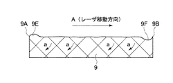
また、第1の溶接工程では、図2に示すように、レーザ溶接機7を、厚板1と薄板2の長手方向の始端位置3から終端位置4に向けて矢示A方向に移動させながらレーザ溶接を行なう。このとき、レーザ溶接機7からのレーザビーム8によって溶融した溶融金属は、図5中に矢印aで示すように、レーザ溶接機7の移動方向Aに対して後側(始端部9A側)へと流動しつつ徐々に凝固していく。このため、図5に示すように、第1の溶接工程で形成された溶接ビード9は、始端部9A側では山形に盛上った盛上り部9Eとなり、終端部9B側では窪み部9Fとなり、これら盛上り部9E、窪み部9Fは、溶接ビード9全体の強度を低下させる要因となるものである。
In the first welding step, as shown in FIG. 2, the
次に、図6及び図7に示すように、第1の溶接工程で形成された溶接ビード9のうち薄板2側のビード止端部9Dに対し、レーザ溶接機7からのレーザビーム8を照射する。そして、このレーザ溶接機7を、厚板1と薄板2の長手方向の終端位置4から始端位置3へと図6中の矢示B方向に移動させることにより、薄板2側のビード止端部9Dを再度溶融させる(第2の溶接工程)。
Next, as shown in FIGS. 6 and 7, the
ここで、図7及び図8に示すように、第2の溶接工程においてレーザ溶接機7から薄板2側のビード止端部9Dに照射されるレーザビーム8の光軸O−Oは、ビード止端部9Dに対して厚板1側に片寄り、直径Dの円形をなすビーム先端(ビームスポット)8Aの照射面積のうち1/2以上がビード止端部9Dに照射される範囲に設定されている。これにより、薄板2側のビード止端部9Dとその周囲の溶接ビード9、薄板2等に対し、レーザビーム8を無駄なく照射することができるようになっている。
Here, as shown in FIGS. 7 and 8, the optical axis OO of the
また、第2の溶接工程では、レーザ溶接機7から薄板2側のビード止端部9Dに照射するレーザビーム8の熱量を、第1の溶接工程で厚板1と薄板2との突合わせ面1A,2Aに照射したレーザビーム8の熱量よりも低く設定している。この場合、本実施の形態では、例えばレーザ溶接機7の出力を制御することにより、第2の溶接工程におけるレーザビーム8の熱量を、第1の溶接工程におけるレーザビーム8の熱量よりも低く設定し、薄板2側のビード止端部9Dが必要以上に溶融するのを抑えることができるようになっている。
Further, in the second welding process, the amount of heat of the
このようにして、第1の溶接工程で形成された溶接ビード9のうち、薄板2側に凸状に張出した薄板2側の止端部9Dに対し、第2の溶接工程においてレーザ溶接機7からのレーザビーム8を照射することにより、この薄板2側の止端部9Dを再度溶融させることができる。この結果、図9に示すように、厚板1と薄板2との間に新たな溶接ビード10が形成された差厚材11を製造することができる。
In this way, the
ここで、第1,第2の溶接工程を経て製造された差厚材11の溶接ビード10は、図9ないし図11に示すように、長手方向の始端部10Aと終端部10Bとを有すると共に、厚板1側のビード止端部10Cと薄板2側のビード止端部10Dとを有している。この場合、薄板2側のビード止端部10Dは、薄板2の表面2Bから滑らかに連続しつつ厚板1側に窪む形状となる。このため、薄板2側のビード止端部10Dと薄板2の表面2Bとの間の段差をなくし、薄板2側のビード止端部10Dに応力が集中するのを抑えることができるので、厚板1と薄板2との溶接強度を高め、差厚材11の信頼性を高めることができる。
Here, the
この場合、第2の溶接工程では、図6に示すように、レーザ溶接機7を厚板1と薄板2の長手方向の終端位置4から始端位置3へと移動させつつ、第1の溶接工程で形成された薄板2側のビード止端部9Dにレーザビーム8を照射している。即ち、第2の溶接工程におけるレーザ溶接機7の移動方向(図6中の矢示B方向)を、第1の溶接工程におけるレーザ溶接機7の移動方向(図2中の矢示A方向)に対して逆向きに設定している。
In this case, in the second welding process, as shown in FIG. 6, the
このとき、溶接ビード9が溶融してなる溶融金属は、図11中に矢印bで示すように、レーザ溶接機7の移動方向Bに対して後側(始端部10A側)へと流動しつつ徐々に凝固していく。このため、図11中に二点鎖線で示す溶接ビード9の盛上り部9Eは、溶接ビード9の溶融金属が矢印b方向に流動することにより平滑化し、溶接ビード9の窪み部9Fは、その内部に溶融金属が充填されることにより平滑化する。この結果、第2の溶接工程によって形成された溶接ビード10の形状を、長手方向の始端部10Aから終端部10Bにかけてほぼ均一化することができ、差厚材11の溶接強度を高めることができる。
At this time, the molten metal formed by melting the
しかも、溶加材6を用いて厚板1と薄板2とを溶接する第1の溶接工程と、第1の溶接工程で形成された薄板2側のビード止端部9Dを再度溶融させる第2の溶接工程とを、単一のレーザ溶接機7を用いて行なうことができるので、差厚材11の製造コストを低減することができる。
In addition, a first welding step of welding the
さらに、レーザ溶接機7は、第1の溶接工程では厚板1と薄板2の長手方向の始端位置3から終端位置4へと移動し、第2の溶接工程では終端位置4から始端位置3へと移動するので、第1の溶接工程と第2の溶接工程とを連続的に実行することができ、厚板1と薄板2とをレーザ溶接するときの作業性を高めることができる。
Further, the
また、本実施の形態によれば、第2の溶接工程におけるレーザビーム8の光軸O−Oを、第1の溶接工程で形成された薄板2側のビード止端部9Dに対し、直径Dの円形をなすビーム先端(ビームスポット)8Aの照射面積のうち1/2以上が照射される範囲に設定することにより、薄板2側のビード止端部9Dとその周囲の溶接ビード9、薄板2等に対し、レーザビーム8を無駄なく照射することができる。
Further, according to the present embodiment, the optical axis OO of the
このため、薄板2側のビード止端部9Dを効率良く溶融させると共に、当該ビード止端部9Dの周囲を加熱して溶融金属のぬれ性を高めることができる。この結果、薄板2の表面2Bとの間に急激な段差を形成するビード止端部9Dを溶融させ、この溶融金属を薄板2側に導くことができるので、新たに形成された溶接ビード10のうち薄板2側のビード止端部10Dの形状を、薄板2の表面2Bに滑らかに連続させることができ、差厚材11の溶接強度を高めることができる。
For this reason, while the
さらに、本実施の形態によれば、レーザ溶接機7から薄板2側のビード止端部9Dに照射するレーザビーム8の熱量を、第1の溶接工程で厚板1と薄板2との突合わせ面1A,2Aに照射したレーザビーム8の熱量よりも低く設定している。これにより、薄板2側のビード止端部9Dが必要以上に溶融してしまうのを抑えることができ、溶接歪みや変形等を抑えることができるので、信頼性の高い差厚材11を製造することができる。
Further, according to the present embodiment, the amount of heat of the
なお、上述した実施の形態では、第2の溶接工程で薄板2側のビード止端部9Dに照射するレーザビーム8の熱量を、第1の溶接工程で厚板1と薄板2との突合わせ面1A,2Aに照射したレーザビーム8の熱量よりも低く設定するため、レーザ溶接機7の出力を制御する場合を例示している。
In the above-described embodiment, the amount of heat of the
しかし、本発明はこれに限るものではなく、例えばレーザ溶接機7の出力は一定に保ち、第2の溶接工程におけるレーザ溶接機7の移動速度を高めることにより、薄板2側のビード止端部9Dに照射されるレーザビーム8の熱量を低下させてもよい。
However, the present invention is not limited to this. For example, by keeping the output of the
また、例えば薄板2側のビード止端部9Dに対するレーザ溶接機7の高さ位置を変化させ、ビード止端部9Dに照射されるレーザビーム8の焦点をぼかす(デフォーカス)ことにより、レーザビーム8の熱量を低下させてもよい。
Further, for example, by changing the height position of the
また、上述した実施の形態では、第2の溶接工程においてレーザ溶接機7から薄板2側の止端部9Dに照射されるレーザビーム8のビーム先端8Aが、直径Dの円形をなすものとして説明している。しかし、本発明はこれに限らず、例えばビーム先端が、楕円形、矩形等の非円形な形状を有するレーザビームを用いてもよい。
Further, in the above-described embodiment, it is assumed that the
1 厚板
1A 突合わせ面
2 薄板
2A 突合わせ面
2B 表面
3 始端位置
4 終端位置
5 交差部
6 溶加材
7 レーザ溶接機
8 レーザビーム
8A ビーム先端
9,10 溶接ビード
9A,10A 始端部
9B,10B 終端部
9C,10C 厚板側の止端部
9D,10D 薄板側の止端部
DESCRIPTION OF
Claims (3)
レーザビームによって溶加材を溶かしながら前記厚板と薄板との突合わせ面にレーザ溶接を施し、前記厚板と薄板との間に溶接ビードを形成する第1の溶接工程と、
前記第1の溶接工程によって形成された前記溶接ビードのうち前記薄板側のビード止端部をレーザビームによって再度溶融させる第2の溶接工程とを有し、
前記第1の溶接工程では、前記厚板と薄板との突合わせ面に沿って始端位置から終端位置に向けてレーザ溶接を行ない、前記第2の溶接工程では、前記第1の溶接工程における溶接方向の終端位置から始端位置に向けて前記薄板側のビード止端部にレーザビームを照射することを特徴とする差厚材のレーザ溶接方法。 In the laser welding method for differential thickness materials in which laser welding is performed by abutting a thick plate and a thin plate having different thicknesses,
A first welding process and facilities the laser welding, to form a weld bead between the thick plate and thin plate abutting surfaces of the thick plate and thin plate while melting the filler metal by a laser beam,
The bead toe portion of the thin side of the weld bead formed by the first welding step to have a second welding step of melting again by the laser beam,
In the first welding step, laser welding is performed from the start end position toward the end position along the abutting surface of the thick plate and the thin plate, and in the second welding step, welding in the first welding step is performed. A laser welding method for a differential thickness material, comprising: irradiating a laser beam to a bead toe end portion on the thin plate side from an end position in a direction toward a start end position .
Priority Applications (1)
| Application Number | Priority Date | Filing Date | Title |
|---|---|---|---|
| JP2006296510A JP5000982B2 (en) | 2006-10-31 | 2006-10-31 | Laser welding method for differential thickness materials |
Applications Claiming Priority (1)
| Application Number | Priority Date | Filing Date | Title |
|---|---|---|---|
| JP2006296510A JP5000982B2 (en) | 2006-10-31 | 2006-10-31 | Laser welding method for differential thickness materials |
Publications (2)
| Publication Number | Publication Date |
|---|---|
| JP2008110390A JP2008110390A (en) | 2008-05-15 |
| JP5000982B2 true JP5000982B2 (en) | 2012-08-15 |
Family
ID=39443210
Family Applications (1)
| Application Number | Title | Priority Date | Filing Date |
|---|---|---|---|
| JP2006296510A Expired - Fee Related JP5000982B2 (en) | 2006-10-31 | 2006-10-31 | Laser welding method for differential thickness materials |
Country Status (1)
| Country | Link |
|---|---|
| JP (1) | JP5000982B2 (en) |
Cited By (1)
| Publication number | Priority date | Publication date | Assignee | Title |
|---|---|---|---|---|
| CN110434450A (en) * | 2019-05-29 | 2019-11-12 | 陕西飞机工业(集团)有限公司 | A kind of Friction stir welding method of step type weld seam |
Families Citing this family (1)
| Publication number | Priority date | Publication date | Assignee | Title |
|---|---|---|---|---|
| JP5609632B2 (en) * | 2010-12-27 | 2014-10-22 | スズキ株式会社 | Laser lap welding method |
Family Cites Families (5)
| Publication number | Priority date | Publication date | Assignee | Title |
|---|---|---|---|---|
| JPH10328860A (en) * | 1997-06-06 | 1998-12-15 | Toshiba Corp | Method and device for laser welding |
| JP2003126978A (en) * | 2001-10-18 | 2003-05-08 | Hitachi Constr Mach Co Ltd | Method for butt welding of different thickness plate materials using laser |
| JP3854490B2 (en) * | 2001-10-25 | 2006-12-06 | 日立建機株式会社 | Laser welding method for differential thickness materials |
| JP2005169410A (en) * | 2003-12-08 | 2005-06-30 | Hitachi Constr Mach Co Ltd | Laser welding method for material of different thickness |
| JP2006218497A (en) * | 2005-02-09 | 2006-08-24 | Nippon Steel Corp | Method for laser beam welding of sheet material |
-
2006
- 2006-10-31 JP JP2006296510A patent/JP5000982B2/en not_active Expired - Fee Related
Cited By (1)
| Publication number | Priority date | Publication date | Assignee | Title |
|---|---|---|---|---|
| CN110434450A (en) * | 2019-05-29 | 2019-11-12 | 陕西飞机工业(集团)有限公司 | A kind of Friction stir welding method of step type weld seam |
Also Published As
| Publication number | Publication date |
|---|---|
| JP2008110390A (en) | 2008-05-15 |
Similar Documents
| Publication | Publication Date | Title |
|---|---|---|
| US20210046585A1 (en) | Laser-beam welding method and laser-beam welding apparatus | |
| WO2015104762A1 (en) | Laser welding method | |
| JPH0557467A (en) | Laser welding method for stocks with different plate thickness | |
| KR20120022787A (en) | Method of hybrid welding and hybrid welding apparatus | |
| JP2005504641A (en) | Method and apparatus for overlap welding two coated metal sheets with high energy density beams | |
| JP6391412B2 (en) | Laser welding method and laser welding apparatus | |
| JP2008264793A (en) | Laser welding method for superimposed workpiece | |
| JP2010167436A (en) | Laser welding method | |
| JP2007229773A (en) | Laser beam welding method and laser beam welding device | |
| JP4378634B2 (en) | Butt laser welding method and butt laser welding apparatus | |
| JP5812527B2 (en) | Hot wire laser welding method and apparatus | |
| JP2005021912A (en) | Laser beam welding method for shape steel | |
| WO2012132024A1 (en) | Laser welding method | |
| JP3854490B2 (en) | Laser welding method for differential thickness materials | |
| JP5000982B2 (en) | Laser welding method for differential thickness materials | |
| JPH08257773A (en) | Laser welding method | |
| JP5121420B2 (en) | Hybrid welding joint | |
| JP5177745B2 (en) | Laminated laser welding method of plated steel sheet and lap laser welding structure of plated steel sheet | |
| JP2003001453A (en) | Combined heat source welding method | |
| JP7060335B2 (en) | Welding equipment and welding method | |
| Victor et al. | Custom beam shaping for high-power fiber laser welding | |
| CN114434009B (en) | Method for manufacturing joined body | |
| JP5108321B2 (en) | Laser welding method | |
| JPH10225782A (en) | Combined welding method by laser and arc | |
| CN114589401A (en) | Infrared laser welding method and device |
Legal Events
| Date | Code | Title | Description |
|---|---|---|---|
| A621 | Written request for application examination |
Free format text: JAPANESE INTERMEDIATE CODE: A621 Effective date: 20081029 |
|
| A977 | Report on retrieval |
Free format text: JAPANESE INTERMEDIATE CODE: A971007 Effective date: 20110310 |
|
| A131 | Notification of reasons for refusal |
Free format text: JAPANESE INTERMEDIATE CODE: A131 Effective date: 20110726 |
|
| A521 | Written amendment |
Free format text: JAPANESE INTERMEDIATE CODE: A523 Effective date: 20110909 |
|
| TRDD | Decision of grant or rejection written | ||
| A01 | Written decision to grant a patent or to grant a registration (utility model) |
Free format text: JAPANESE INTERMEDIATE CODE: A01 Effective date: 20120515 |
|
| A01 | Written decision to grant a patent or to grant a registration (utility model) |
Free format text: JAPANESE INTERMEDIATE CODE: A01 |
|
| A61 | First payment of annual fees (during grant procedure) |
Free format text: JAPANESE INTERMEDIATE CODE: A61 Effective date: 20120517 |
|
| R150 | Certificate of patent or registration of utility model |
Ref document number: 5000982 Country of ref document: JP Free format text: JAPANESE INTERMEDIATE CODE: R150 Free format text: JAPANESE INTERMEDIATE CODE: R150 |
|
| FPAY | Renewal fee payment (event date is renewal date of database) |
Free format text: PAYMENT UNTIL: 20150525 Year of fee payment: 3 |
|
| LAPS | Cancellation because of no payment of annual fees |