JP5000751B2 - Travel stabilization mechanism for ground-travel excavator - Google Patents
Travel stabilization mechanism for ground-travel excavator Download PDFInfo
- Publication number
- JP5000751B2 JP5000751B2 JP2010158176A JP2010158176A JP5000751B2 JP 5000751 B2 JP5000751 B2 JP 5000751B2 JP 2010158176 A JP2010158176 A JP 2010158176A JP 2010158176 A JP2010158176 A JP 2010158176A JP 5000751 B2 JP5000751 B2 JP 5000751B2
- Authority
- JP
- Japan
- Prior art keywords
- excavator
- ground
- traveling
- ground traveling
- cable
- Prior art date
- Legal status (The legal status is an assumption and is not a legal conclusion. Google has not performed a legal analysis and makes no representation as to the accuracy of the status listed.)
- Active
Links
Images


Landscapes
- Component Parts Of Construction Machinery (AREA)
Description
本発明は、ニューマチックケーソン工法等を用いて掘削作業を行う際に、地上走行式掘削機が、転倒したり、ケーブル切断のために走行不能になったりすることを、防止する技術に関する。さらには、本発明は、かかる地上走行式掘削機の走行装置が大きく傾く等して走行不能状態となった際に、復旧する技術に関する。 The present invention relates to a technique for preventing a ground traveling excavator from falling over or being unable to travel due to cable cutting when excavation work is performed using a pneumatic caisson method or the like. Furthermore, the present invention relates to a technique for recovering when the traveling device of such a ground excavator becomes incapable of traveling due to a large inclination.
橋脚基礎構造や、立坑、地下構造物等を水底地盤中に構築する際の工法として、例えばニューマチックケーソン工法(潜函工法とも称される)が知られている。ニューマチックケーソン工法では、筒状のケーソン本体の底部分に、ケーソン作業室が設けられる。ケーソン作業室は、側面を刃口部で覆われ、且つ、上面を天井スラブ(すなわち、ケーソン本体の底部に貼られたコンクリート板)で覆われる。そして、ケーソン作業室内の気圧を圧縮空気で調整することで水位を調節しながら、水底地盤を掘削していくことにより、ケーソン本体を徐々に地中深くまで沈下させていく。ニューマチックケーソン工法は、例えば、下記特許文献1に開示されている。 For example, a pneumatic caisson method (also referred to as a submersible method) is known as a method for constructing a pier foundation structure, a shaft, an underground structure, or the like in a submarine ground. In the pneumatic caisson method, a caisson working chamber is provided at the bottom of the cylindrical caisson body. The side of the caisson working chamber is covered with a blade edge, and the upper surface is covered with a ceiling slab (that is, a concrete plate affixed to the bottom of the caisson body). Then, the caisson body is gradually submerged deeply by excavating the water bottom ground while adjusting the water level by adjusting the air pressure in the caisson working chamber with compressed air. The pneumatic caisson method is disclosed in Patent Document 1 below, for example.
上述のように、ニューマチックケーソン工法では、ケーソン作業室内の気圧を調整することによって、水位が調整される。このため、ケーソン本体を深く沈下させていくほど、ケーソン作業室内の気圧を高くしていく必要がある。この結果、ケーソン本体を非常に深くまで沈下させた場合、ケーソン作業室内の気圧が非常に高くなることから、長時間の掘削作業によって作業員が潜函病等を煩うおそれがある。したがって、気圧が所定値よりも高い場合は、通常、ケーソン作業室内を無人状態にし、地上から掘削機を遠隔操作することによって掘削作業を行う。 As described above, in the pneumatic caisson method, the water level is adjusted by adjusting the atmospheric pressure in the caisson working chamber. For this reason, it is necessary to raise the atmospheric pressure in the caisson working chamber as the caisson body sinks deeper. As a result, when the caisson body is submerged very deeply, the air pressure in the caisson working chamber becomes very high, so that there is a possibility that the worker may bother with a latent disease due to a long excavation work. Therefore, when the atmospheric pressure is higher than a predetermined value, the caisson work chamber is usually unmanned and excavation work is performed by remotely operating the excavator from the ground.
遠隔操作で掘削作業を行う場合、掘削機として、天井走行式のものを使用する場合が多い。天井走行式掘削機は、天井スラブに敷設されたレールに案内されてケーソン作業室内を移動しつつ、水中地盤を掘削する。天井走行式掘削機は、例えば下記特許文献2に開示されている。 When excavation work is performed remotely, an excavator is often used that is overhead traveling. An overhead traveling excavator is guided by rails laid on a ceiling slab and excavates the underwater ground while moving in a caisson working chamber. An overhead traveling excavator is disclosed in, for example, Patent Document 2 below.
天井走行式掘削機には、該掘削機が水中地盤の穴や段差のために転倒等して走行不能になるおそれが無いという利点がある。その反面、天井走行式掘削機は、非常に高価であるとともに、ニューマチックケーソン工法等の限られた工法でしか使用できないという欠点がある。また、天井走行式掘削機はサイズが大きいため、ケーソン本体の径が小さい場合(したがって、ケーソン作業室の掘削作業面積が小さい場合)には、使用できないという欠点もある。 The overhead traveling excavator has an advantage that the excavator is not likely to be unable to travel due to a fall or the like due to a hole or a step in the underwater ground. On the other hand, overhead traveling excavators are very expensive and have the disadvantage that they can only be used with limited methods such as the pneumatic caisson method. Further, since the overhead traveling excavator is large, there is a disadvantage that it cannot be used when the diameter of the caisson body is small (thus, when the excavation work area of the caisson working chamber is small).
これに対して、遠隔操作の地上走行式掘削機を使用すれば、汎用の掘削機を流用することができ、小型の汎用機も既に存在することから、ケーソン本体の径の大小に拘わらず、非常に安価に掘削作業を行うことができる。しかしながら、ケーソン作業室内で遠隔操作型の地上走行式掘削機を使用する場合、以下のような欠点が生じる。 On the other hand, if a remotely operated ground traveling excavator is used, a general-purpose excavator can be diverted, and since a small general-purpose machine already exists, regardless of the diameter of the caisson body, Excavation work can be performed at a very low cost. However, when using a remotely operated ground traveling excavator in the caisson work room, the following drawbacks occur.
地上走行式掘削機を使用する場合、該掘削機が段差に乗り上げてしまって転倒するおそれや、大きく傾く等して走行不能になるおそれがある。走行不能に陥った場合、作業員がケーソン作業室内に入って、復旧作業を行う必要がある。 When using a ground traveling excavator, there is a risk that the excavator may climb over a step and fall down, or may be unable to travel due to a large inclination. If the vehicle becomes unable to run, the worker must enter the caisson work room and perform recovery work.
また、掘削機を遠隔操作するためには、かかる掘削機と地上の遠隔操作システムとを、制御ケーブルで接続する必要がある。また、ケーソン作業室内では電動式掘削機を使用するため(エンジン駆動式を使用するとケーソン作業室内に排気ガスが充満するため)、かかる掘削機と地上の電源とを電源ケーブルで接続する必要もある。しかしながら、地上走行式掘削機を使用する場合、これらケーブルは水中地盤上を引きずることになるため、ケーブルの切断事故が発生しやすい。ケーブルが切断された場合、作業員がケーソン作業室内に入って、ケーブルの交換等を行う必要がある。 Further, in order to remotely operate the excavator, it is necessary to connect the excavator and the ground remote operation system with a control cable. In addition, since an electric excavator is used in the caisson work room (exhaust gas is filled in the caisson work room when the engine drive type is used), it is also necessary to connect the excavator and the ground power supply with a power cable. . However, when a ground traveling excavator is used, since these cables are dragged on the underwater ground, cable cutting accidents are likely to occur. When the cable is cut, it is necessary for the worker to enter the caisson work room and replace the cable.
このように、地上走行式掘削機を使用する場合には、作業員が作業室内に入らなければならないことが多くなり、このため、作業員が潜函病等を煩う危険性が高くなる。 As described above, when using a ground traveling excavator, the worker often has to enter the working chamber, and therefore, the risk that the worker is bothered with a latent disease or the like increases.
本発明の課題は、地上走行式掘削機が転倒やケーブル切断して走行不能になることを防止することができ、さらには、地上走行式掘削機が大きく傾く等して走行不能状態となった際に無人で復旧することができる、地上走行式掘削機の走行安定化機構を提供する点にある。 The problem of the present invention is that the ground traveling excavator can be prevented from falling and being unable to travel due to a cable cut, and further, the ground traveling excavator has become unable to travel due to a large inclination or the like. It is in the point which provides the traveling stabilization mechanism of a ground traveling type excavator which can be restored unattended.
請求項1に係る発明は、作業室内で掘削作業を行う地上走行式掘削機の走行安定化機構であって、前記作業室の天井に固定されたレールと、該レールに案内されて移動するプレーントロリと、一端側が前記地上走行式掘削機に接続され且つ他端側が前記プレーントロリに接続された転倒防止用索状部材とを有する転倒防止機構を備えることを特徴とする。 The invention according to claim 1 is a travel stabilization mechanism for a ground traveling excavator that performs excavation work in a work chamber, and a rail that is fixed to a ceiling of the work chamber, and a plane that is guided and moved by the rail. There is provided a fall prevention mechanism comprising a trolley and a fall-preventing rope-like member having one end connected to the ground excavator and the other end connected to the plain trolley.
請求項2に記載の発明は、請求項1に記載の構成に加えて、前記地上走行式掘削機に、上方向への引っ張り力に応じて伸延する伸縮部材が固定され、且つ、該伸縮部材の上端部に、前記転倒防止用索状部材の前記他端側が接続されたことを特徴とする。 According to a second aspect of the present invention, in addition to the configuration of the first aspect, an elastic member that extends in response to an upward pulling force is fixed to the ground traveling excavator, and the elastic member The other end side of the fall-preventing rope-like member is connected to the upper end of the cable.
請求項3に記載の発明は、請求項2に記載の構成に加えて、前記伸縮部材が、外筒部と、該外筒部の内側に設けられ、該外筒部から露出する方向に相対移動することによって該伸縮部材を延伸させる内筒部と、該伸縮部材の延伸に対して応力を発生させるバネ機構とを備えることを特徴とする。 According to a third aspect of the present invention, in addition to the configuration according to the second aspect, the elastic member is provided on the outer cylinder part and on the inner side of the outer cylinder part, and is relative to the direction exposed from the outer cylinder part. It is characterized by comprising an inner cylinder part that extends the elastic member by moving, and a spring mechanism that generates a stress with respect to the extension of the elastic member.
請求項4に記載の発明は、請求項1〜3の何れかに記載の構成に加えて、一端側が前記地上走行式掘削機に接続され且つ他端側が前記プレーントロリに接続された復旧用索状部材と、該復旧用索状部材を巻き取ることにより、前記地上走行式掘削機に引っ張り力を加えるウインチとを有する復旧機構をさらに備えることを特徴とする。 According to a fourth aspect of the present invention, in addition to the configuration according to any one of the first to third aspects, a recovery cord in which one end side is connected to the ground traveling excavator and the other end side is connected to the plane trolley. And a recovery mechanism having a winch that applies a pulling force to the ground traveling excavator by winding the recovery cable-shaped member.
請求項5に記載の発明は、請求項1〜4の何れかに記載の構成に加えて、複数の前記地上走行式掘削機に対応する複数の前記プレーントロリが1本の前記レールに配設され、且つ、該複数のプレーントロリの移動範囲を個別に制限することによって該地上走行式掘削機の走行範囲をそれぞれ制限するための、1又は複数のストッパが、該レールに設けられたことを特徴とする。 According to a fifth aspect of the present invention, in addition to the configuration according to any one of the first to fourth aspects, a plurality of the plane trolleys corresponding to the plurality of ground traveling excavators are arranged on one rail. And the rail is provided with one or more stoppers for restricting the travel range of the ground excavator by individually restricting the movement range of the plurality of plane trolleys. Features.
請求項6に記載の発明は、請求項1〜5の何れかに記載の構成に加えて、前記作業室外の装置と前記地上走行式掘削機とを接続するケーブルと、前記レールに案内されて移動し、該ケーブルを所定間隔で保持して吊り下げるための複数のケーブルリールとを備えることを特徴とする。
請求項7に記載の発明は、請求項1〜6の何れかに記載の構成に加えて、前記プレーントロリに、該プレーントロリ用の自走装置が設けられたことを特徴とする。
In addition to the structure in any one of Claims 1-5, the invention of Claim 6 is guided by the rail which connects the apparatus outside the said working room, and the said ground traveling excavator, and the said rail. And a plurality of cable reels for moving and holding the cable at predetermined intervals and suspending the cable.
The invention according to claim 7 is characterized in that, in addition to the configuration according to any one of claims 1 to 6, the plane trolley is provided with a self-propelled device for the plane trolley.
請求項1の発明によれば、プレーントロリと地上走行式掘削機とを転倒防止用索状部材で接続することとしたので、該地上走行式掘削機の転倒を防止することができる。また、作業室の天井にレールを固定し、このレールによって該プレーントロリを案内する構造としたので、転倒防止用索状部材が地上走行式掘削機の移動を妨げることはない。 According to the first aspect of the present invention, since the plain trolley and the ground traveling excavator are connected by the fall-preventing rope-like member, the ground traveling excavator can be prevented from falling. Further, since the rail is fixed to the ceiling of the work room and the plain trolley is guided by the rail, the fall-preventing rope-shaped member does not hinder the movement of the ground traveling excavator.
請求項2の発明によれば、上方向への引っ張り力に応じて伸延する伸縮部材を該地上走行式掘削機に固定し、該伸縮部材の上端部に転倒防止用索状部材を接続することとしたので、該地上走行式掘削機が転倒するおそれはさらに低くなる。 According to the second aspect of the present invention, the telescopic member extending in response to the upward pulling force is fixed to the ground traveling excavator, and the fall-preventing cord-like member is connected to the upper end of the telescopic member. Therefore, the risk that the ground traveling excavator will fall is further reduced.
請求項3の発明によれば、伸縮部材を外筒部、内筒部及びバネ機構を用いて構成したので、地上走行式掘削機の上方向への引っ張り力に応じて伸延する伸縮部材を、簡単な構成で安価に得ることができる。 According to the invention of claim 3, since the elastic member is configured using the outer cylinder part, the inner cylinder part, and the spring mechanism, the elastic member that extends according to the upward pulling force of the ground traveling excavator is provided. It can be obtained inexpensively with a simple configuration.
請求項4に記載の発明によれば、地上走行式掘削機とプレーントロリとを復旧用索状部材で接続するとともに、該復旧用索状部材を巻き取るウインチを設けたので、復旧時に該地上走行式掘削機を引き上げる方向に力を加えることができ、したがって、復旧作業が容易になる。 According to the fourth aspect of the present invention, the ground traveling excavator and the plane trolley are connected by the restoration rope-shaped member, and the winch for winding the restoration rope-shaped member is provided. A force can be applied in the direction in which the traveling excavator is pulled up, thus facilitating the recovery operation.
請求項5に記載の発明によれば、レールにストッパを設けることで複数のプレーントロリの移動範囲を個別に制限し、これによって地上走行式掘削機の走行範囲をそれぞれ制限することができる。したがって、複数の地上走行式掘削機を同時に遠隔操作する際の、操作が容易になる。 According to the fifth aspect of the present invention, it is possible to individually limit the moving ranges of the plurality of plane trolleys by providing the stoppers on the rails, thereby limiting the traveling ranges of the ground traveling excavator. Therefore, the operation when simultaneously remotely operating a plurality of ground traveling excavators is facilitated.
請求項6に記載の発明によれば、地上走行式掘削機に接続されたケーブルを、ケーブルリールで吊り下げ、該ケーブルリールがレールに案内されて移動するようにしたため、該ケーブルの断線を防止することができる。
請求項7に記載の発明によれば、プレーントロリに該プレーントロリ用の自走装置を設けたので、地上走行式掘削機の走行装置に頼ることなしに該地上走行式掘削機の水平移動ができる。
According to the sixth aspect of the present invention, the cable connected to the ground excavator is suspended by the cable reel so that the cable reel moves while being guided by the rail, so that the cable is prevented from being disconnected. can do.
According to the seventh aspect of the present invention, since the plane trolley is provided with the self-propelled device for the plane trolley, the ground traveling excavator can move horizontally without relying on the traveling device of the ground traveling excavator. it can.
以下、本発明の一実施形態について、図面を用いて説明する。 Hereinafter, an embodiment of the present invention will be described with reference to the drawings.
図1は、本実施形態に係る走行安定化機構100を備えた地上走行式掘削機110の全体構成を概略的に示す側面図である。
FIG. 1 is a side view schematically showing the overall configuration of a
図1に示したように、本実施形態に係る走行安定化機構100は、レール120、プレーントロリ130、転倒防止チェーン140及び伸縮管150を有する転倒防止機構と、復旧ワイヤ160及びウインチ170を有する復旧機構と、ケーブル180とを備えている。
As shown in FIG. 1, the
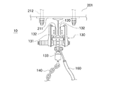
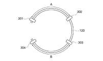
レール120としては、例えばI型綱を使用することができる。図2の正面図に拡大して示したように、レール120は固定金具211に固定されており、さらに、この固定金具211はアンカーボルト212を用いてケーソン作業室10の天井スラブ201に固定されている。また、図3の概念的平面図に示したように、本実施形態では、このレール120をリング状に構成する。そして、レール120の所定位置には、ストッパ301,302,303,304が取り付けられている。これらストッパ301〜304により、プレーントロリ130の走行範囲を制限することができる。例えば、1本のレール120に二台のプレーントロリ130を設置して二台の地上走行式掘削機110を同時に使用する場合、図3にA,Bで示した範囲に、対応するプレーントロリ130の移動範囲を制限できる。このようにして移動可能範囲を制限することにより、各地上走行式掘削機110の遠隔操作が容易になる。
As the
プレーントロリ130は、4個の車輪132(図2では2個のみ示されている)を備える。車輪132は、I型レール120の左右両側に2個ずつ配置され、それぞれ本体部131に回転自在に支持されている。これらの車輪132により、プレーントロリ130は、レール120に案内されて、天井スラブ201上を移動することができる。チェーン取り付け金具133には、転倒防止チェーン140が取り付けられる。また、ワイヤ取り付け金具134には、復旧ワイヤ160が取り付けられる。プレーントロリ130は、自走機構(電動モータ等)を備えていない。このため、プレーントロリ130は、地上走行式掘削機110の移動に伴って転倒防止チェーン140に引っ張られることで、移動する。車輪132は、ストッパ301〜304を越えて移動することはできない。したがって、プレーントロリ130は、例えばストッパ301,302の間又はストッパ303,304の間のみを、移動することができる。
The
転倒防止チェーン140は、一端側が地上走行式掘削機110(本実施形態では伸縮管150の上端部分)に接続され且つ他端側がプレーントロリ130に接続されている。後述するように、この転倒防止チェーン140は、地上走行式掘削機110の転倒を防止するために使用される。なお、転倒防止チェーン140に代えて、例えばワイヤやロープ等、他の種類の索状部材を使用することも可能である。地上走行式掘削機110の重量に耐え得る強度を有するものであれば、転倒防止用の索状部材として使用できる。
The
伸縮管150は、地上走行式掘削機110上に設置される。この伸縮管150は、地上走行式掘削機110の上方向への引っ張り力に応じて、伸延する。本実施形態の伸縮管150は、延伸長さに応じてバネ定数が増大するように構成される。伸縮管150の詳細構造については、後述する。
The
復旧ワイヤ160は、一端側が地上走行式掘削機110に接続され且つ他端側がプレーントロリ130に接続されている。本実施形態では、復旧ワイヤ160の一端側は、ウインチ170に接続される。後述するように、この復旧ワイヤ160は、地上走行式掘削機110が走行不能になったときの復旧に使用される。なお、復旧ワイヤ160に代えて、例えばチェーンやロープ等、他の種類の索状部材を使用することも可能である。地上走行式掘削機110の重量に耐え得る強度を有するものであれば、復旧用の索状部材として使用できる。
The
ウインチ170は、復旧ワイヤ160を巻き取るために使用される。この巻き取り動作により、地上走行式掘削機110を持ち上げる方向に引っ張り力を加えることができる。本実施形態では、ウインチ170を伸縮管150に固定してるが、他の場所でも良い。本実施形態では、ウインチ170の駆動力は、地上走行式掘削機110が水中地盤に与える荷重を減らせる程度或いは地上走行式掘削機110の一方の走行装置を浮き上がらせる程度でもよい。
The
ケーブル180は、地上の遠隔操作システムや電源を地上走行式掘削機110に電気接続するために使用される。後述するように、本実施形態では、ケーブル180が水中地盤に接触しないようにすることで、該ケーブル180の切断事故を防止する。
The
次に、伸縮管150の詳細構造について、図4を用いて説明する。
Next, the detailed structure of the
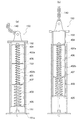
図4(a)は、伸縮管150の内部構造を示す概念的側面図である。図4(a)に示したように、伸縮管150は、外筒部151と、内筒部152と、バネ機構153とを備えている。内筒部152は、外筒部151の内側に配置されている。そして、外筒部151から露出する方向に内筒部152を相対移動させることによって、伸縮管150を延伸させることができる。また、内筒部152の上端部分には、転倒防止チェーン140が取り付けられる。
FIG. 4A is a conceptual side view showing the internal structure of the
バネ機構153は、このような伸縮管150の延伸に対して、応力を発生させる。バネ機構153は、心棒401と、スプリング402a,402b,403と、留め板404,405と、位置決め板406,407とを備えている。心棒401は、外筒部151の底板151aに固定されている。スプリング402a,402bとスプリング403とは、バネ定数が異なっている。図4(a)の例では、2個のスプリング402a,402bと、これらスプリング402a,402bよりもバネ定数が大きい1個のスプリング403とを、使用している。これらのスプリング402a,402b,403は、心棒401を貫通させて、それぞれ直列に配置される。各スプリング402a,402b,403は、留め板404,405及び位置決め板406,407に挟まれた状態で、それぞれ配置される。留め板404は、心棒401の上端付近に固定される。一方、留め板405は、内筒部152の底部に固定される。また、位置決め板406,407は、スプリング402a,402b,403の間に上下動自在に配置される。位置決め板406,407により、内筒部152の内壁面とスプリング402a,402b,403との距離を略均一に保つことができる。
The
図4(b)は、伸縮管150を延伸させた状態を示している。図4(b)に示したように、転倒防止チェーン140に引っ張られて内筒部152が上昇すると、これに伴って、下側の留め板405も上昇する。これに対して、上側の留め板404は、心棒401に固定されているため、上昇しない。また、位置決め板406,407は、上述のように上下動自在である。したがって、内筒部152が上昇したとき、留め板404,405の間隔が狭まり、その結果、スプリング402a,402b,403が圧縮される。これによって、バネ機構153に、応力が発生する。
FIG. 4B shows a state in which the
上述したように、スプリング402a,402bのバネ定数は、スプリング403のバネ定数よりも小さい。このため、伸縮管150の延伸長さが小さいときはスプリング402a,402bの圧縮が支配的となり、スプリング402a,402bがある程度圧縮されるとスプリング403も圧縮されるようになる。したがって、延伸管150全体としてのバネ定数も、伸縮管150の延伸長さが小さいときはスプリング402a,402bのバネ定数に近い値になり、伸縮管150がある程度延伸するとこれよりも大きい値になる。このようにして、本実施形態の伸縮管150は、延伸長さに応じてバネ定数が増大する。この結果、正常な移動や掘削作業の最中(すなわち、伸縮管150の延伸長さが小さいとき)は、バネ定数が小さいために該移動等を妨げられることが無く、その一方で、地上走行式掘削機110が傾斜等したとき(すなわち、伸縮管150の延伸長さが大きくなったとき)には、バネ定数も大きくなるために該地上走行式掘削機110の転倒等を有効に防止することができる(後述)。
As described above, the spring constants of the
図5は、本実施形態で使用するケーブルリールを示す概念図である。 FIG. 5 is a conceptual diagram showing a cable reel used in the present embodiment.
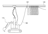
図5に示したように、本実施形態では、レール120に、複数のケーブルリール501を設置する。そして、これらのケーブルリール501に、ケーブル180を、任意の間隔で保持させる。すなわち、ケーブル180は、ケーブルリール501を介して、レール120に吊り下げられた状態になる。ケーブル180の保持間隔は、該ケーブル180が水中地盤に接触しないように、決定される。これらケーブルリール501は、レール120に案内されて、移動することができる。これにより、ケーブル180が水中地盤面で引きずられて切断されたり絡まったりするといった、不都合を回避できる。
As shown in FIG. 5, in this embodiment, a plurality of
次に、本実施形態に係る転倒防止機構及び復旧機構の動作について説明する。図6は、本実施形態に係る転倒防止機構の動作を説明するための概念図である。また、図7は、本実施形態に係る普及機構の動作を説明するための概念図である。 Next, operations of the fall prevention mechanism and the recovery mechanism according to the present embodiment will be described. FIG. 6 is a conceptual diagram for explaining the operation of the overturn prevention mechanism according to the present embodiment. FIG. 7 is a conceptual diagram for explaining the operation of the dissemination mechanism according to the present embodiment.
地上走行式掘削機110が水中地盤上に正常状態(すなわち、実質的に傾斜していない状態)にあるとき、転倒防止チェーン140及び復旧ワイヤ160は、レール120と地上走行式掘削機110との距離に比較して十分に長く、弛んだ状態となる(図1参照)。このため、地上走行式掘削機110が、転倒防止チェーン140や復旧ワイヤ160によって引っ張られることはなく、したがって、これら転倒防止チェーン140等が掘削作業の障害になることはない。
When the
また、地上走行式掘削機110が正常に移動するとき、転倒防止チェーン140に引っ張られて、プレーントロリ130がレール120上を移動する。このため、地上走行式掘削機110は、所定の移動範囲内で自由に移動することができる。
Further, when the
さらには、掘削作業時や走行時等に、地上走行式掘削機110がわずかに傾く等したために転倒防止チェーン140に引っ張り力が生じて、伸縮管150がわずかに延伸したとしても、このときの伸縮管150の応力は小さいので(上述)、掘削作業等の妨げになることはない。
Further, even when the
これに対して、例えば、水中地盤601の傾斜等のために地上走行式掘削機110が大きく傾いた場合(図6参照)、転倒防止チェーン140が伸縮管150を強く引っ張ることになり、したがって、この伸縮管150は大きく延伸する。この場合、上述したような理由から、伸縮管150の応力は非常に大きくなる。これにより、地上走行式掘削機110の転倒を有効に防止することができる。
On the other hand, for example, when the
また、例えば、一方の走行装置111が水中地盤701の穴702内に入り込んでしまった場合等には、地上走行式掘削機110が走行不能状態に陥る場合がある(図7参照)。このような場合、地上の操作者は、ウインチ170を遠隔操作することによって復旧ワイヤ160を巻き取る。これにより、復旧ワイヤ160が、地上走行式掘削機110に引っ張り力を与える。この際、ウインチ170は、地上走行式掘削機110を完全に釣り上げる必要は無く、水中地盤に与える荷重を減らせる程度或いは地上走行式掘削機110の一方の走行装置を浮き上がらせる程度でもよい。これにより、他方の走行装置112を駆動させたときに、走行装置111を穴702から脱出させ易くなる。
In addition, for example, when one
また、地上走行式掘削機110が走行できないほど傾斜した場合にも、ウインチ170で復旧ワイヤ160を巻き取ることで該地上走行式掘削機110を起こし、正常な状態となる場所に移動させることが可能である。
In addition, even when the
さらには、地上走行式掘削機110が完全に転倒してしまった場合にも、ウインチ170で復旧ワイヤ160を巻き取ることで該地上走行式掘削機110を起こすことができる場合がある。
Furthermore, even when the
一方、走行装置111を穴702から脱出させることができず、作業員がケーソン作業室10内に入って復旧作業を行う場合でも、復旧ワイヤ160とウインチ170とを用いて地上走行式掘削機110を引っ張ることにより、作業員の作業時間や負担を軽減して、潜函病等のおそれを低減できる。
On the other hand, even when the traveling
以上説明したように、本実施形態によれば、プレーントロリ130と地上走行式掘削機110とを転倒防止チェーン140で接続することとしたので、地上走行式掘削機110の転倒を防止することができる。また、ケーソン作業室10の天井にレール120を固定し、このレールによってプレーントロリ130を案内する構造としたので、転倒防止チェーン140によって地上走行式掘削機の移動が妨げられることがない。
As described above, according to the present embodiment, since the
本実施形態によれば、伸縮管150を地上走行式掘削機110に搭載して、該伸縮管150の上端部分に転倒防止チェーン140を繋ぐこととしたので、地上走行式掘削機110が転倒するおそれを、さらに低くすることができる。
According to the present embodiment, the
本実施形態によれば、伸縮管150を、外筒部151、内筒部152及びバネ機構153を用いて構成した。これにより、伸縮管150を、簡単な構成で安価に構成できる。
According to this embodiment, the
本実施形態によれば、伸縮管150の延伸長さに応じてバネ定数が増大するので、正常な掘削作業や移動を妨げることが無く、且つ、地上走行式掘削機110が傾斜等したときには転倒を有効に防止できる。
According to the present embodiment, the spring constant increases in accordance with the extension length of the
本実施形態によれば、地上走行式掘削機110とプレーントロリ130とを復旧ワイヤ160で接続するとともに、この復旧ワイヤ160をウインチ170で巻き取ることができるので、復旧時に、地上走行式掘削機110を引っ張り上げる方向に力を加えて復旧作業を容易にすることができる。ウインチ170はプレーントロリ130側に取り付ける場合もある。
本実施形態によれば、プレーントロリにプレーントロリの自走装置を取り付けて遠隔操作する場合は、地上走行式掘削機110の走行装置に頼ることなしに地上走行式掘削機110の水平移動ができる。
According to the present embodiment, the
According to this embodiment, when a plane trolley self-propelled device is attached to the plane trolley and remotely operated, the ground-
本実施形態によれば、レール120にストッパ301〜304を設けることで各プレーントロリ130の移動範囲を個別に制限し、これによって地上走行式掘削機110の走行範囲をそれぞれ制限することができる。したがって、複数の地上走行式掘削機110を同時に遠隔操作する際の、操作が容易になる。
According to the present embodiment, by providing the
加えて、本実施形態によれば、地上走行式掘削機110に接続されたケーブル180を、ケーブルリール501で吊り下げ、これらのケーブルリール501がレール120に案内されて移動するようにしたため、ケーブル180の断線や絡まりを防止することができる。
In addition, according to the present embodiment, the
以上、本実施形態では、ニューマチックケーソン工法を用いた掘削作業を例に採って説明したが、本発明は他の工法にも適用することができる。 As described above, in the present embodiment, the excavation work using the pneumatic caisson method has been described as an example, but the present invention can also be applied to other methods.
また、本実施形態では、バネ機構153において、3個のスプリング402a,402b,403を使用し、且つ、バネ定数を二種類としたが(図4参照)、スプリングの個数やバネ定数の種類は任意に決定できる。
In this embodiment, the
さらに、本実施形態では、4個のストッパ301〜304を使用して、プレーントロリ130の移動範囲を二種類設定したが、一種類或いは三種類以上でも良い。
Furthermore, in this embodiment, two types of movement ranges of the
本実施形態では、転倒防止チェーン140と伸縮管150とを用いて地上走行式掘削機110の転倒を防止することとしたが、索状部材を用いる方法や、上方向に伸縮する伸縮部材と索状部材とを組み合わせる方法であれば、他の構造を採用することも可能である。
In this embodiment, the
本実施形態では、レール120をリング状に構成したが、例えば直線状等、他の構造としても良い。
In the present embodiment, the
本発明は、地上走行式掘削機を使用することができる分野、すなわち土木建築分野に適用することができる。 The present invention can be applied to a field where a ground traveling excavator can be used, that is, a civil engineering field.
10 ケーソン作業室
100 走行安定化機構
110 地上走行式掘削機
120 レール
130 プレーントロリ
131 本体部
132 車輪
133 チェーン取り付け金具
134 ワイヤ取り付け金具
140 転倒防止チェーン
150 伸縮管
160 復旧ワイヤ
170 ウインチ
180 ケーブル
201 天井スラブ
211 固定金具
212 アンカーボルト
301,302,303,304 ストッパ
401 心棒
402a,402b,403 スプリング
404,405 留め板
406,407 位置決め板
501 ケーブルリール
DESCRIPTION OF
Claims (7)
前記作業室の天井に固定されたレールと、
該レールに案内されて移動するプレーントロリと、
一端側が前記地上走行式掘削機に接続され且つ他端側が前記プレーントロリに接続された転倒防止用索状部材と、
を有する転倒防止機構を備えることを特徴とする地上走行式掘削機の走行安定化機構。 A traveling stabilization mechanism for a ground traveling excavator that performs excavation work in a work chamber,
A rail fixed to the ceiling of the working chamber;
A plain trolley guided and moved by the rail;
A cable member for preventing overturning, one end of which is connected to the ground excavator and the other end is connected to the plain trolley;
A traveling stabilization mechanism for a ground traveling excavator, comprising: a fall prevention mechanism including:
該伸縮部材の上端部に、前記転倒防止用索状部材の前記他端側が接続された、
ことを特徴とする請求項1に記載の地上走行式掘削機の走行安定化機構。 A telescopic member that extends according to the upward pulling force of the ground traveling excavator is fixed to the ground traveling excavator, and
The other end side of the cable member for preventing overturning is connected to the upper end of the elastic member,
The traveling stabilization mechanism for a ground traveling excavator according to claim 1.
外筒部と、
該外筒部の内側に設けられ、該外筒部から露出する方向に相対移動することによって該伸縮部材を延伸させる内筒部と、
該伸縮部材の延伸に対して応力を発生させるバネ機構と、
を備えることを特徴とする請求項2に記載の地上走行式掘削機の走行安定化機構。 The elastic member is
An outer cylinder,
An inner cylinder part that is provided inside the outer cylinder part and extends the elastic member by moving in a direction exposed from the outer cylinder part;
A spring mechanism for generating stress with respect to stretching of the elastic member;
The traveling stabilization mechanism for a ground traveling excavator according to claim 2, comprising:
該復旧用索状部材を巻き取ることにより、前記地上走行式掘削機に引っ張り力を加えるウインチと、
を有する復旧機構をさらに備えることを特徴とする請求項1〜3の何れかに記載の地上走行式掘削機の走行安定化機構。 A cord member for restoration having one end connected to the ground excavator and the other end connected to the plain trolley;
A winch that applies a tensile force to the ground traveling excavator by winding the cable member for restoration;
The travel stabilization mechanism for a ground traveling excavator according to any one of claims 1 to 3, further comprising a recovery mechanism having the following.
該複数のプレーントロリの移動範囲を個別に制限することによって該地上走行式掘削機の走行範囲をそれぞれ制限するための、1又は複数のストッパが、該レールに設けられた、
ことを特徴とする請求項1〜4の何れかに記載の地上走行式掘削機の走行安定化機構。 A plurality of the plane trolleys corresponding to the plurality of ground traveling excavators are disposed on one rail, and
One or a plurality of stoppers are provided on the rail to limit the traveling range of the ground excavator by individually limiting the moving range of the plurality of plane trolleys,
The traveling stabilization mechanism for a ground traveling excavator according to any one of claims 1 to 4.
前記レールに案内されて移動し、該ケーブルを所定間隔で保持して吊り下げるための複数のケーブルリールと、
を備えることを特徴とする請求項1〜5の何れかに記載の地上走行式掘削機の走行安定化機構。 A cable for connecting the outdoor equipment of the work room and the ground traveling excavator;
A plurality of cable reels for moving while being guided by the rails and holding and suspending the cables at predetermined intervals;
A travel stabilization mechanism for a ground traveling excavator according to any one of claims 1 to 5.
Priority Applications (1)
| Application Number | Priority Date | Filing Date | Title |
|---|---|---|---|
| JP2010158176A JP5000751B2 (en) | 2010-07-12 | 2010-07-12 | Travel stabilization mechanism for ground-travel excavator |
Applications Claiming Priority (1)
| Application Number | Priority Date | Filing Date | Title |
|---|---|---|---|
| JP2010158176A JP5000751B2 (en) | 2010-07-12 | 2010-07-12 | Travel stabilization mechanism for ground-travel excavator |
Publications (2)
| Publication Number | Publication Date |
|---|---|
| JP2012021281A JP2012021281A (en) | 2012-02-02 |
| JP5000751B2 true JP5000751B2 (en) | 2012-08-15 |
Family
ID=45775755
Family Applications (1)
| Application Number | Title | Priority Date | Filing Date |
|---|---|---|---|
| JP2010158176A Active JP5000751B2 (en) | 2010-07-12 | 2010-07-12 | Travel stabilization mechanism for ground-travel excavator |
Country Status (1)
| Country | Link |
|---|---|
| JP (1) | JP5000751B2 (en) |
Families Citing this family (1)
| Publication number | Priority date | Publication date | Assignee | Title |
|---|---|---|---|---|
| CN116695822B (en) * | 2023-06-20 | 2025-09-16 | 徐州徐工挖掘机械有限公司 | Power supply system and control method of electric towing excavator and electric towing excavator |
Family Cites Families (3)
| Publication number | Priority date | Publication date | Assignee | Title |
|---|---|---|---|---|
| JPS59116452U (en) * | 1983-01-25 | 1984-08-06 | 株式会社豊田自動織機製作所 | Fall prevention device for track running backhoe shovels |
| JP2003285988A (en) * | 2002-03-29 | 2003-10-07 | Kito Corp | Trolley |
| JP2009108612A (en) * | 2007-10-31 | 2009-05-21 | Maeda Corp | Moist curing apparatus for lining concrete |
-
2010
- 2010-07-12 JP JP2010158176A patent/JP5000751B2/en active Active
Also Published As
| Publication number | Publication date |
|---|---|
| JP2012021281A (en) | 2012-02-02 |
Similar Documents
| Publication | Publication Date | Title |
|---|---|---|
| KR102019053B1 (en) | Telescopic boom crane and launch and recovery apparatus for rov lars thereof | |
| EP3683336A1 (en) | Marine tensile anode system and installation method thereof | |
| EP3268583B1 (en) | Subsea grab system and marine vessel having such subsea grab system | |
| JP2017109819A (en) | Swing prevention device of suspension hook | |
| JP2018503521A (en) | Salvage sawing system and method | |
| JP5912828B2 (en) | Vertical excavation and excavation method and vertical excavation and excavation equipment | |
| CN207782294U (en) | Cable dragging device | |
| KR101650676B1 (en) | Multi-stage telescopic arm device and deep-digging excavator comprising multi-stage telescopic arm device | |
| JP5000751B2 (en) | Travel stabilization mechanism for ground-travel excavator | |
| CN111355188A (en) | Live crossing construction method for high-voltage line | |
| JP2021173011A (en) | Soil retention wall construction method | |
| CN104831623B (en) | A kind of across pier suspension bracket self-propelling device | |
| KR101651048B1 (en) | Multi-stage telescopic arm device and deep-digging excavator comprising multi-stage telescopic arm device | |
| CN105003738A (en) | Construction method for mounting large-diameter pipe by applying cableway in complex mountain terrain | |
| JP2018111922A (en) | Excavator | |
| CN209905017U (en) | Laying device and box culvert inspection operation system | |
| JP6289918B2 (en) | Earth drill machine | |
| KR20140135186A (en) | Mobile sealed building consisting of a plurality of sections | |
| JP6200150B2 (en) | Remote ball remover | |
| CN220745081U (en) | Suspension protection structure capable of adjusting deformation of existing pipeline | |
| KR20090089519A (en) | Gangfoam lifting device | |
| JP6428714B2 (en) | Mobile crane | |
| KR101708321B1 (en) | Mast standing up apparatus | |
| CN111634393A (en) | Inspection operation system for deployment device and box culvert | |
| JP7340238B2 (en) | Hydraulic hose holding device and drilling method |
Legal Events
| Date | Code | Title | Description |
|---|---|---|---|
| A977 | Report on retrieval |
Free format text: JAPANESE INTERMEDIATE CODE: A971007 Effective date: 20120427 |
|
| TRDD | Decision of grant or rejection written | ||
| A01 | Written decision to grant a patent or to grant a registration (utility model) |
Free format text: JAPANESE INTERMEDIATE CODE: A01 Effective date: 20120515 |
|
| A01 | Written decision to grant a patent or to grant a registration (utility model) |
Free format text: JAPANESE INTERMEDIATE CODE: A01 |
|
| A61 | First payment of annual fees (during grant procedure) |
Free format text: JAPANESE INTERMEDIATE CODE: A61 Effective date: 20120516 |
|
| R150 | Certificate of patent or registration of utility model |
Ref document number: 5000751 Country of ref document: JP Free format text: JAPANESE INTERMEDIATE CODE: R150 Free format text: JAPANESE INTERMEDIATE CODE: R150 |
|
| FPAY | Renewal fee payment (event date is renewal date of database) |
Free format text: PAYMENT UNTIL: 20150525 Year of fee payment: 3 |