JP5000409B2 - Ink supply system - Google Patents
Ink supply system Download PDFInfo
- Publication number
- JP5000409B2 JP5000409B2 JP2007194207A JP2007194207A JP5000409B2 JP 5000409 B2 JP5000409 B2 JP 5000409B2 JP 2007194207 A JP2007194207 A JP 2007194207A JP 2007194207 A JP2007194207 A JP 2007194207A JP 5000409 B2 JP5000409 B2 JP 5000409B2
- Authority
- JP
- Japan
- Prior art keywords
- ink
- ink supply
- filter
- supply system
- adapter
- Prior art date
- Legal status (The legal status is an assumption and is not a legal conclusion. Google has not performed a legal analysis and makes no representation as to the accuracy of the status listed.)
- Active
Links
Images
Classifications
-
- B—PERFORMING OPERATIONS; TRANSPORTING
- B41—PRINTING; LINING MACHINES; TYPEWRITERS; STAMPS
- B41J—TYPEWRITERS; SELECTIVE PRINTING MECHANISMS, i.e. MECHANISMS PRINTING OTHERWISE THAN FROM A FORME; CORRECTION OF TYPOGRAPHICAL ERRORS
- B41J2/00—Typewriters or selective printing mechanisms characterised by the printing or marking process for which they are designed
- B41J2/005—Typewriters or selective printing mechanisms characterised by the printing or marking process for which they are designed characterised by bringing liquid or particles selectively into contact with a printing material
- B41J2/01—Ink jet
- B41J2/17—Ink jet characterised by ink handling
- B41J2/175—Ink supply systems ; Circuit parts therefor
- B41J2/17563—Ink filters
Landscapes
- Ink Jet (AREA)
Description
本発明はインク供給システムに関し、特に画像形成装置本体のインクカートリッジ装着部に装着されるアダプタを介してインクを供給するインク供給システムに関する。 The present invention relates to an ink supply system, and more particularly to an ink supply system that supplies ink via an adapter mounted on an ink cartridge mounting portion of an image forming apparatus main body.
プリンタ、ファクシミリ、複写装置、これらの複合機等の画像形成装置として、例えば、液体の液滴を吐出する液体吐出ヘッドで構成した記録ヘッドを含む液体吐出装置を用いて、媒体(以下「用紙」ともいうが材質を限定するものではなく、また、被記録媒体、記録媒体、転写材、記録紙なども同義で使用する。)を搬送しながら、液体を用紙に付着させて画像形成(記録、印刷、印写、印字も同義語で用いる。)を行うものがある。 As an image forming apparatus such as a printer, a facsimile machine, a copying machine, and a multifunction machine of these, for example, a liquid discharge apparatus including a recording head composed of a liquid discharge head that discharges liquid droplets is used. However, the material is not limited, and a recording medium, a recording medium, a transfer material, a recording paper, and the like are also used synonymously.) Printing, printing, and printing are also used synonymously).
なお、本発明においては、画像形成装置は、紙、糸、繊維、布帛、皮革、金属、プラスチック、ガラス、木材、セラミックス等の媒体に液体を吐出して画像形成を行う装置を意味し、また、「画像形成」とは、文字や図形等の意味を持つ画像を媒体に対して付与することだけでなく、パターン等の意味を持たない画像を媒体に付与することをも意味する。また、「インク」とは、厳密な意味でのインクに限るものではなく、上記の意味での画像形成を行うことができる液体の総称として用いる。 In the present invention, the image forming apparatus means an apparatus for forming an image by discharging liquid onto a medium such as paper, thread, fiber, fabric, leather, metal, plastic, glass, wood, ceramics, etc. “Image formation” means not only that an image having a meaning such as a character or a figure is imparted to the medium but also an image having no meaning such as a pattern is imparted to the medium. The term “ink” is not limited to ink in a strict sense, but is used as a general term for liquids that can perform image formation in the above sense.
このような画像形成装置(以下、単に「インクジェット記録装置」ともいう。)においては、インクを記録ヘッドに供給するためにインクカートリッジがよく用いられている。こうしたインクカートリッジは、記録ヘッドと共にキャリッジに搭載されたり、あるいは専用のインクカートリッジ装着部に着脱自在に装着され供給チューブを介して記録ヘッド側のサブタンクへインクを供給することができるようにされている。 In such an image forming apparatus (hereinafter also simply referred to as “inkjet recording apparatus”), an ink cartridge is often used to supply ink to a recording head. Such an ink cartridge is mounted on a carriage together with a recording head, or is detachably mounted on a dedicated ink cartridge mounting portion so that ink can be supplied to a sub tank on the recording head side via a supply tube. .
この場合、装置本体にインクカートリッジを収納するため、インクカートリッジ内に設けられたインク収容部は概して容量が小さく、インクを大量に消費することを目的としたユーザーは頻繁にカートリッジ交換の手間が課せられていることになる。 In this case, since the ink cartridge is accommodated in the apparatus main body, the capacity of the ink container provided in the ink cartridge is generally small, and a user who intends to consume a large amount of ink frequently needs to replace the cartridge. Will be.
そこで、例えば特許文献1に記載されているように、画像形成装置本体外に大容量のインク貯蔵部を設け、このインク貯蔵部と装置本体内のインク収容部に固定したアダプタとの間をチューブで接続して、装置本体にインクを供給するインク供給システムが知られている。
一方、インクジェット記録装置において、記録ヘッドに供給するインク中にゴミなどの異物が混入するとノズル詰まりを生じて吐出不良を生じるため、記録ヘッドへのインク供給路中にフィルタを介装して異物を除去するようにしている。 On the other hand, in an ink jet recording apparatus, if foreign matter such as dust enters the ink supplied to the recording head, nozzle clogging occurs and ejection failure occurs. Therefore, a foreign substance is removed by inserting a filter in the ink supply path to the recording head. Try to remove.
この場合、装置本体に備えられるフィルタは一般的には固定式であるが、特許文献2、3に記載されているように装置本体へのインク導入部をフィルタユニットとして、このフィルタユニットを交換可能とすることも知られている。
その他、次のような文献もある。
しかしながら、上記特許文献1に記載されているインク供給システムにあっては、装置本体に備えられたフィルタを利用してインク内に含有するゴミや粗大粒子などの異物をフィルタリングしているが、装置本体のフィルタによってインク供給に支障無く取り除ける異物の量は有限であるため、インクの使用可能な量にはおのずと限界がある。 However, in the ink supply system described in Patent Document 1, foreign substances such as dust and coarse particles contained in the ink are filtered using a filter provided in the apparatus main body. Since the amount of foreign matter that can be removed without hindrance to the ink supply by the filter of the main body is finite, the amount of ink that can be used is naturally limited.
そこで、特許文献2、3に記載のされているように装置本体側のフィルタを交換可能にすることが考えられるものの、装置本体のインク導入部はカートリッジを押し嵌めることを前提として構成されているため、カートリッジを挿入する細く狭いスリットの奥深くにあり、指などを差し込んでフィルタを交換することは容易ではない。 Therefore, although it is conceivable that the filter on the apparatus main body side can be replaced as described in Patent Documents 2 and 3, the ink introduction part of the apparatus main body is configured on the assumption that the cartridge is pushed in. Therefore, it is deep in the narrow narrow slit into which the cartridge is inserted, and it is not easy to replace the filter by inserting a finger or the like.
本発明は上記の課題に鑑みてなされたものであり、インク貯蔵部を備えるインク供給システムを長期に亘って使用できるようにすることを目的とする。 SUMMARY An advantage of some aspects of the invention is that an ink supply system including an ink storage unit can be used over a long period of time.
上記の課題を解決するため、本発明に係るインク供給システムは、
インクを貯留するインク貯蔵部と、
画像形成装置本体のインクカートリッジが着脱自在に装着されるカートリッジ装着部に着脱自在に装着され、前記画像形成装置本体との接続部を有するアダプタと、
前記インク貯蔵部と前記アダプタの接続部とを接続し、インク供給経路を形成する供給チューブと、
前記インク貯蔵部から前記アダプタの接続部までのインク供給経路に設けられたフィルタと、を備え、
前記フィルタは交換可能に設けられ、
前記インク貯蔵部から前記アダプタの接続部までのインク供給経路中であって、前記フィルタよりインク供給経路の下流側に前記インク供給経路を大気に開放する大気開放弁が設けられている
構成とした。
In order to solve the above problems, an ink supply system according to the present invention includes:
An ink storage section for storing ink;
An adapter that is detachably mounted on a cartridge mounting portion on which an ink cartridge of the image forming apparatus main body is detachably mounted, and has a connection portion with the image forming apparatus main body
A supply tube that connects the ink storage part and the connection part of the adapter and forms an ink supply path;
A filter provided in an ink supply path from the ink storage unit to the connection portion of the adapter,
The filter is provided interchangeably ,
An air release valve that opens the ink supply path to the atmosphere is provided in the ink supply path from the ink storage part to the connection part of the adapter and downstream of the filter. > Configuration.
本発明に係るインク供給システムによれば、フィルタを交換することによって長期に亘って使用することができる。 According to the ink supply system according to the present invention can be used for a long period by exchanging filter.
以下、本発明の実施の形態について添付図面を参照して説明する。まず、本発明に係るインク供給システムによってインクを供給する画像形成装置の一例について図1及び図2を参照して説明する。なお、図1は同画像形成装置の全体構成を説明する側面説明図、図2は同装置の要部平面説明図である。
この画像形成装置はシリアル型インクジェット記録装置であり、装置本体1の左右の側板21A、21Bに横架したガイド部材である主従のガイドロッド31、32でキャリッジ33を主走査方向に摺動自在に保持し、図示しない主走査モータによってタイミングベルトを介して図2で矢示方向(キャリッジ主走査方向)に移動走査する。
Embodiments of the present invention will be described below with reference to the accompanying drawings. First, an example of an image forming apparatus that supplies ink by the ink supply system according to the present invention will be described with reference to FIGS. 1 and 2. FIG. 1 is an explanatory side view for explaining the overall configuration of the image forming apparatus, and FIG. 2 is an explanatory plan view of a main part of the apparatus.
This image forming apparatus is a serial type ink jet recording apparatus, and a
このキャリッジ33には、イエロー(Y)、シアン(C)、マゼンタ(M)、ブラック(K)の各色のインク滴を吐出するための記録ヘッド34a、34b(区別しないときは「記録ヘッド34」という。)を複数のノズルからなるノズル列を主走査方向と直交する副走査方向に配列し、インク滴吐出方向を下方に向けて装着している。
The
記録ヘッド34は、それぞれ2つのノズル列を有し、記録ヘッド34aの一方のノズル列はブラック(K)の液滴を、他方のノズル列はシアン(C)の液滴を、記録ヘッド34bの一方のノズル列はマゼンタ(M)の液滴を、他方のノズル列はイエロー(Y)の液滴を、それぞれ吐出する。
Each of the
また、キャリッジ33には、記録ヘッド34のノズル列に対応して各色のインクを供給するための第2インク供給部であるサブタンク35a、35b(区別しないときは「サブタンク35」という。)を搭載している。このサブタンク35には、カートリッジ装填部4に着脱自在に装着される各色の第1インク供給部であるインクカートリッジ10y、10m、10c、10kから、供給ポンプユニット5によって各色の供給チューブ36を介して、各色の記録液が補充供給される。
The
一方、給紙トレイ2の用紙積載部(圧板)41上に積載した用紙42を給紙するための給紙部として、用紙積載部41から用紙42を1枚ずつ分離給送する半月コロ(給紙コロ)43及び給紙コロ43に対向し、摩擦係数の大きな材質からなる分離パッド44を備え、この分離パッド44は給紙コロ43側に付勢されている。
On the other hand, as a paper feeding unit for feeding the
そして、この給紙部から給紙された用紙42を記録ヘッド34の下方側に送り込むために、用紙42を案内するガイド部材45と、カウンタローラ46と、搬送ガイド部材47と、先端加圧コロ49を有する押さえ部材48とを備えるとともに、給送された用紙42を静電吸着して記録ヘッド34に対向する位置で搬送するための搬送手段である搬送ベルト51を備えている。
In order to feed the
この搬送ベルト51は、無端状ベルトであり、搬送ローラ52とテンションローラ53との間に掛け渡されて、ベルト搬送方向(副走査方向)に周回するように構成している。また、この搬送ベルト51の表面を帯電させるための帯電手段である帯電ローラ56を備えている。この帯電ローラ56は、搬送ベルト51の表層に接触し、搬送ベルト51の回動に従動して回転するように配置されている。この搬送ベルト51は、図示しない副走査モータによってタイミングを介して搬送ローラ52が回転駆動されることによって図2のベルト搬送方向に周回移動する。
The
さらに、記録ヘッド34で記録された用紙42を排紙するための排紙部として、搬送ベルト51から用紙42を分離するための分離爪61と、排紙ローラ62及び排紙コロである拍車63とを備え、排紙ローラ62の下方に排紙トレイ3を備えている。
Further, as a paper discharge unit for discharging the
また、装置本体1の背面部には両面ユニット71が着脱自在に装着されている。この両面ユニット71は搬送ベルト51の逆方向回転で戻される用紙42を取り込んで反転させて再度カウンタローラ46と搬送ベルト51との間に給紙する。また、この両面ユニット71の上面は手差しトレイ72としている。
A duplex unit 71 is detachably mounted on the back surface of the apparatus body 1. The duplex unit 71 takes in the
さらに、図2に示すように、キャリッジ33の走査方向一方側の非印字領域には、記録ヘッド34のノズルの状態を維持し、回復するための維持回復機構81を配置している。この維持回復機構81には、記録ヘッド34の各ノズル面をキャピングするための各キャップ部材(以下「キャップ」という。)82a、82b(区別しないときは「キャップ82」という。)と、ノズル面をワイピングするためのワイパ部材(ワイパブレード)83と、増粘した記録液を排出するために記録に寄与しない液滴を吐出させる空吐出を行うときの液滴を受ける空吐出受け84と、この空吐出受け84に一体形成され、ワイパブレード83に付着したインクを除去するための清掃部材であるワイパクリーナ部85と、ワイパブレード83のクリーニング時にワイパブレード83をワイパクリーナ85側に押し付けるワイパクリーナ86と、キャリッジ22をロックするキャリッジロック87などとを備えている。また、このヘッドの維持回復機構81の下方側には維持回復動作によって生じる廃液を収容するための廃液タンク100が装置本体に対して交換可能に装着される。
Further, as shown in FIG. 2, a maintenance /
また、図2に示すように、キャリッジ33の走査方向他方側の非印字領域には、記録中などに増粘した記録液を排出するために記録に寄与しない液滴を吐出させる空吐出を行うときの液滴を受ける空吐出受け88を配置し、この空吐出受け88には記録ヘッド34のノズル列方向に沿った開口部89などを備えている。
In addition, as shown in FIG. 2, in the non-printing area on the other side in the scanning direction of the
このように構成したこの画像形成装置においては、給紙トレイ2から用紙42が1枚ずつ分離給紙され、略鉛直上方に給紙された用紙42はガイド45で案内され、搬送ベルト51とカウンタローラ46との間に挟まれて搬送され、更に先端を搬送ガイド37で案内されて先端加圧コロ49で搬送ベルト51に押し付けられ、略90°搬送方向を転換される。
In this image forming apparatus configured as described above, the
このとき、帯電ローラ56に対してプラス出力とマイナス出力とが交互に繰り返すように、つまり交番する電圧が印加され、搬送ベルト51が交番する帯電電圧パターン、すなわち、周回方向である副走査方向に、プラスとマイナスが所定の幅で帯状に交互に帯電されたものとなる。このプラス、マイナス交互に帯電した搬送ベルト51上に用紙42が給送されると、用紙42が搬送ベルト51に吸着され、搬送ベルト51の周回移動によって用紙42が副走査方向に搬送される。
At this time, a positive output and a negative output are alternately repeated with respect to the charging
そこで、キャリッジ33を移動させながら画像信号に応じて記録ヘッド34を駆動することにより、停止している用紙42にインク滴を吐出して1行分を記録し、用紙42を所定量搬送後、次の行の記録を行う。記録終了信号又は用紙42の後端が記録領域に到達した信号を受けることにより、記録動作を終了して、用紙42を排紙トレイ3に排紙する。
Therefore, by driving the
そして、記録ヘッド34のノズルの維持回復を行うときには、キャリッジ33をホーム位置である維持回復機構81に対向する位置に移動して、キャップ部材82によるキャッピングを行ってノズルからの吸引を行うノズル吸引、画像形成に寄与しない液滴を吐出する空吐出などの維持回復動作を行うことにより、安定した液滴吐出による画像形成を行うことができる。
When performing the maintenance and recovery of the nozzles of the
次に、インクカートリッジ10の一例について図3及び図4をも参照して説明する。
このインクカートリッジ10は、カートリッジケース(筺体)102内にインクを収容した記録液収容手段であるインク袋103を収納したものである。このカートリッジケース102は、分解及び組立て可能に2分割された第1ケース(ベース)121と第2ケース(ケース)122とで構成されている。
Next, an example of the
The
そして、カートリッジケース102には内部に収納したインク袋103のインク供給口部131に対応して開口部123を形成している。
The
このインクカートリッジ10をカートリッジ装填部4に装着したときに、カートリッジ装着部4の奥側に設けた中空針がインク袋103の供給口部131内に刺通されて、インク袋103内部と供給ポンプユニット24とが連通状態となり、インク袋103内のインクを装置本体1側に供給可能になる。
When the
また、このインクカートリッジ10の前面側上部には、EEPROMなどからなる書替え可能な記憶素子(記憶手段)である不揮発性メモリ130を設けている。この不揮発性メモリ130には、インクカートリッジ10に関する情報、例えば、インク色、インク種、使用期限、ID番号、純正情報、再充填回数、インク残量などに関する固有の情報を記憶されるとともに、バージョン情報(Ver情報)や画像形成装置本体側の制御プログラムの更新プログラムなどが記憶される。
Further, a
そして、このインクカートリッジ10をカートリッジ装填部4に装着することで、装置本体側の電極と電気的に接続されて、不揮発性メモリ130に記憶されている情報が装置本体側に読み出し可能となり、また、装置本体側から不揮発性メモリ130に対する書き込みが可能となる。
By mounting the
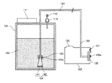
次に、本発明に係るインク供給システムの第1実施形態について図5及び図6を参照して説明する。なお、図5は同実施形態の全体構成を示す模式的説明図、図6は同じくフィルタユニット部分の拡大説明図である。
インク100を貯留するインク貯蔵部101と、前記インクジェット記録装置本体のインクカートリッジ10が着脱自在に装着されるカートリッジ装着部4に着脱自在に装着される、記録装置本体との接続部120を有するアダプタ102と、インク貯蔵部101とアダプタ102の接続部120を接続するインク供給経路を形成する供給チューブ103と、インク貯蔵部101からアダプタ102の接続部120までのインク供給経路に設けられたフィルタユニット104とを備えている。
Next, a first embodiment of the ink supply system according to the present invention will be described with reference to FIGS. 5 is a schematic explanatory view showing the overall configuration of the embodiment, and FIG. 6 is an enlarged explanatory view of the filter unit portion.
An adapter having an
インク貯蔵部101には、内部にインク100を注入するため開口部を覆う蓋111と、内部を大気に開放する大気開放弁112と、内部の空気を強制排出するための空気ポンプ113とを備えている。
The
アダプタ102には、記録装置本体のカートリッジ装着部4の奥側に設けた中空針が刺通される弾性部材120aを含む接続部120とともに、IC121、識別リブ122などが設けられる。このアダプタ102の内部を中空としている。このアダプタ102には、前述した記録装置本体側が設けているインク供給ユニットの識別機能をパスする機能が設けられており、具体的にはインク色の識別のための突起(上記識別リブ)や適宜、情報の書き込みや読み出しが可能な情報記録媒体(上記IC121)などを備えている。
The
フィルタユニット104は、インク貯蔵部101とアダプタ102との間のインク供給経路を形成する供給チューブ103の途中に設けられている。このフィルタユニット104は、図6に示すように、フィルタ141と、このフィルタ141の両側に設けたホーン形状の導入路部142、142とを一体化して構成されている。そして、このフィルタユニット104は、供給チューブ103を接続したジョイント105、105間に導入路部142、142をそれぞれO−リング105a、105aを介して連結することで、供給チューブ103接続されている。
The
なお、インク貯蔵部101には適宜インク残量を検知する残量検知センサが備えられていてもよい。また、目視でインク貯蔵部101内のインク残量がわかるよう、インク貯蔵部101は光を透過する部材で一部ないし全体が形成されていてもよい。また、アダプタ102の接続部120に供給チューブ103を直接接続しているが、アダプタ102内に供給チューブ103が接続されてインク貯蔵部101からインクが供給されるインク収容手段を設け、このインク収容手段に接続部120を設ける構成とすることもできる。
Note that the
このように構成したインク供給システムにおいては、インクジェット記録装置本体のカートリッジ装着部4内にインクカートリッジ10に代えてアダプタ102を装着した状態で、インク貯蔵部101から供給チューブ103、フィルタユニット104を介してアダプタ102の接続部120にインクが供給され、接続部120に刺し通された図示しない中空針を介してインクジェット記録装置本体側にインクが供給される。
In the ink supply system configured as described above, the
このときフィルタユニット104のフィルタ141によってインク貯蔵部101から供給される異物が除去される。フィルタ141を交換する場合には、ジョイント105に設けられたO−リング105aに差し込まれたフィルタユニット104の導入路部142をジョイント105から引き抜いて、新たなフィルタユニット141をジョイント105のO−リング105aに差し込むことで交換することができる。
At this time, the foreign matter supplied from the
また、初期充填時やフィルタ141の交換を行った後で、インク供給路に進入した気泡を排出する必要がある。この場合、大気開放弁112を開放状態にして、空気ポンプ113でインク貯蔵部101内に空気を送り込み、その圧力でインク100を押し出して、気泡をインク100ごと排出する。また、図7に示すように、アダプタ102の接続部120から注射器200等でインク100ごと気泡を吸い出すようにしてもよい。
Further, it is necessary to discharge bubbles that have entered the ink supply path after initial filling or after the
これに対して、例えば、図20に示す比較例のインク供給システムのように、アダプタ502の記録装置本体への供給口部(接続部)520にフィルタ541を固定して設けた構成では、フィルタ541の交換にはアダプタ520ごと交換する必要があり不経済である。
On the other hand, for example, in the configuration in which the
このように、インクを貯留するインク貯蔵部と、画像形成装置本体のインクカートリッジが着脱自在に装着されるカートリッジ装着部に着脱自在に装着され、画像形成装置本体との接続部を有するアダプタと、インク貯蔵部とアダプタの接続部とを接続し、インク供給経路を形成する供給チューブと、インク貯蔵部からアダプタの接続部までのインク供給経路に設けられたフィルタと、を備え、フィルタは交換可能に設けられていることで、フィルタを交換することによってインクを継ぎ足しながら長期に亘って使用することができる。 As described above, an ink storage section that stores ink, an adapter that is detachably mounted on a cartridge mounting section in which an ink cartridge of the image forming apparatus main body is detachably mounted, and has a connection section with the image forming apparatus main body, The ink storage section is connected to the adapter connection section to form an ink supply path, and the filter is provided in the ink supply path from the ink storage section to the adapter connection section. By replacing the filter, the ink can be used over a long period of time while adding the ink.
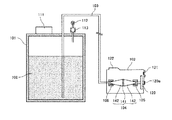
次に、本発明に係るインク供給システムの第2実施形態について図8及び図9を参照して説明する。なお、図8は同実施形態の全体構成を示す模式的説明図、図9は同じくフィルタユニット部分の拡大説明図である。
ここでは、交換可能なフィルタユニット141をインク供給経路のインク貯蔵部101側の末端に設けている。この実施形態では、図9にも示すように、フィルタユニット141とのジョイント部105は一つでよく、記録装置本体との接続部120が閉じているためジョイント部105からインクが漏れ出す量も極僅かでインク供給経路に気泡が入り難くなる。
Next, a second embodiment of the ink supply system according to the present invention will be described with reference to FIGS. FIG. 8 is a schematic explanatory view showing the overall configuration of the embodiment, and FIG. 9 is an enlarged explanatory view of the filter unit portion.
Here, a
また、インク貯蔵部101に設けられた蓋111に対応する開口部は容易にフィルタユニット104ごと外に取り出せるよう前記第1実施形態より大きくしている、つまり、フィルタユニット141を取り出し可能な開口部としているので、容易にフィルタ141の交換が可能である。なお、フィルタ交換時の気泡の排出方法は前記第1実施形態と同様にして行うことができる。
Further, the opening corresponding to the
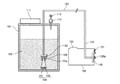
次に、本発明に係るインク供給システムの第3実施形態について図10を参照して説明する。なお、図10は同実施形態の全体構成を示す模式的説明図である。
ここでは、アダプタ102内にフィルタユニット104を設けている。フィルタユニット104と接続部120をアダプタ102内に集約することで、構成が簡単になる。
Next, a third embodiment of the ink supply system according to the present invention will be described with reference to FIG. FIG. 10 is a schematic explanatory view showing the overall configuration of the embodiment.
Here, the
また、インク供給システムのインク供給経路(供給チューブ)の下流側にあたる記録装置本体との接続部120の直前にフィルタユニット141を配置することで、インク供給経路(供給チューブ103)内から発生する異物もフィルタリングできるようになる。なお、フィルタ交換時の気泡の排出方法は前記第1実施形態と同様にして行うことができる。
In addition, by arranging the
次に、本発明に係るインク供給システムの第4実施形態について図11を参照して説明する。なお、図11は同実施形態の全体構成を示す模式的説明図である。
ここでは、上記第1実施形態において、フィルタユニット104の前後(上流側及び下流側)にインク供給経路(供給チューブ103)を開閉可能な弁151、152をそれぞれ設けている。弁151、152を設けることで、フィルタユニット104のフィルタ141を交換するときには、弁151、151を閉じることで物理的にインクの漏れ出し、インク供給経路への気泡の入り込みを防止することができる。
Next, a fourth embodiment of the ink supply system according to the present invention will be described with reference to FIG. FIG. 11 is a schematic explanatory diagram showing the overall configuration of the embodiment.
Here, in the first embodiment,
次に、本発明に係るインク供給システムの第5実施形態について図12を参照して説明する。なお、図12は同実施形態の全体構成を示す模式的説明図である。
ここでは、上記第2実施形態において、フィルタユニット104の後(下流側)にインク供給経路(供給チューブ103)を開閉可能な弁152を設けている。弁152を設けることで、フィルタユニット104のフィルタ141を交換するときには、弁152を閉じることで物理的にインクの漏れ出し、インク供給経路への気泡の入り込みを防止することができる。さらに、上記第4実施形態と比べて、弁は一つで済み、第2実施形態と比べてもインクの漏れ出しはさらに少なくなる。
Next, a fifth embodiment of the ink supply system according to the present invention will be described with reference to FIG. FIG. 12 is a schematic explanatory view showing the overall configuration of the embodiment.
Here, in the second embodiment, a
次に、本発明に係るインク供給システムの第6実施形態について図13を参照して説明する。なお、図13は同実施形態の全体構成を示す模式的説明図である。
ここでは、上記第3実施形態において、アダプタ102内のフィルタユニット104の前(上流側)にインク供給経路(供給チューブ103)を開閉可能な弁151を設けている。弁151を設けることで、フィルタユニット104のフィルタ141を交換するときには、弁151を閉じることで物理的にインクの漏れ出し、インク供給経路への気泡の入り込みを防止することができる。さらに、上記第3実施形態と比べてもインクの漏れ出し、インク供給経路への気泡の入り込みをより確実に防止することができる。
Next, a sixth embodiment of the ink supply system according to the present invention will be described with reference to FIG. FIG. 13 is a schematic explanatory diagram showing the overall configuration of the embodiment.
Here, in the third embodiment, a
次に、本発明に係るインク供給システムの第7実施形態について図14を参照して説明する。なお、図14は同実施形態の全体構成を示す模式的説明図である。
ここでは、前記第1実施形態におけるインク貯蔵部101に代えて、可撓性を有するインク袋201を設けている。前記第1実施形態と比べてインク貯蔵部を低コストで構成できる。また、フィルタ交換時の気泡の排出方法は前記第1実施形態で説明したと同様に、注射器でインクごと排出する方法のほか、インク貯蔵部(インク袋201)自体が可撓性を有しているので、インク袋201を押圧してインクごと気泡を排出することを容易に行える。
Next, a seventh embodiment of the ink supply system according to the present invention will be described with reference to FIG. FIG. 14 is a schematic explanatory diagram showing the overall configuration of the embodiment.
Here, in place of the
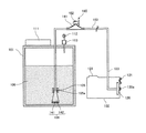
次に、本発明に係るインク供給システムの第8実施形態について図15を参照して説明する。なお、図15は同実施形態の全体構成を示す模式的説明図である。
ここでは、前記第2実施形態において、インク供給経路(供給チューブ103)の途中に、インク供給経路を大気に開放する大気開放路161と、この大気開放路161を開閉する開閉弁(大気開放弁)162とからなる気泡排出ユニット160を設けている。これにより、フィルタ141の交換などでインク供給経路内へ侵入した気泡を大気開放路161に誘導して大気開放弁162を介して排出することができる。
Next, an eighth embodiment of the ink supply system according to the present invention will be described with reference to FIG. FIG. 15 is a schematic explanatory view showing the overall configuration of the embodiment.
Here, in the second embodiment, in the middle of the ink supply path (supply tube 103), an
このとき、フィルタ141よりインク供給経路の上流側にあるインクは圧力を加えることでフィルタ141を通過可能だが、フィルタ141より下流側の気泡はフィルタ141を圧力をかけることなしに越えられないため、気泡排出ユニット160はフィルタユニット104よりインク供給経路の下流側に設けている。
At this time, ink on the upstream side of the ink supply path from the
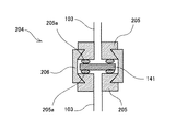
次に、本発明に係るインク供給システムの第9実施形態について図16及び図17を参照して説明する。なお、図16は同実施形態の全体構成を示す模式的説明図、図17はフィルタユニット部分の拡大説明図である。
ここでは、前記第1実施形態におけるフィルタユニット104に代えて、図17に示すフィルタユニット204を設けている。このフィルタユニット204は、供給チューブ103を接続したジョイント205、205間にO−リング205a、205aを介してフィルタ141を挟み持ち、ジョイント205、205を係合部材206で結合して構成されている。係合部材206と各ジョイント205は凹凸嵌合で連結されており、O−エネルギー印具205aの復元力によって強固に連結されている。
Next, a ninth embodiment of the ink supply system according to the present invention will be described with reference to FIGS. 16 is a schematic explanatory view showing the overall configuration of the embodiment, and FIG. 17 is an enlarged explanatory view of a filter unit portion.
Here, a
このように構成したので、フィルタ141を交換するときにはフィルタユニット204のジョイント205を連結する係合部材206を取り外すことで分解できるので、フィルタ141のみを単独で交換することができ、低コスト化を図れる。
Since it comprised in this way, when replacing | exchanging the
次に、本発明に係るインク供給システムの第10実施形態について図18及び図19を参照して説明する。なお、図18は同実施形態の全体構成を示す模式的説明図、図19はフィルタユニット部分の拡大説明図である
ここでは、前記第2実施形態におけるフィルタユニット104に代えて、図19に示すフィルタユニット204を設けている。このフィルタユニット204は、前記第9実施形態のフィルタユニット204の一方のジョイント205に供給チューブ103を接続していない点で異なるのみである。
Next, a tenth embodiment of the ink supply system according to the present invention will be described with reference to FIGS. 18 is a schematic explanatory view showing the overall configuration of the embodiment, and FIG. 19 is an enlarged explanatory view of the filter unit portion. Here, instead of the
なお、これらの第9、第10実施形態における気泡排出方法は前述した第1ないし第8実施形態と同様であり、また、第3ないし第8実施形態のフィルタユニット104に代えてフィルタユニット204を適用することもできる。
The bubble discharging methods in the ninth and tenth embodiments are the same as those in the first to eighth embodiments, and the
10…インクカートリッジ
34…記録ヘッド
35…サブタンク
100…インク
101…インク貯蔵部
102…アダプタ
103…供給チューブ(インク供給経路)
104、204…フィルタユニット
105、205…ジョイント
141…フィルタ
DESCRIPTION OF
104, 204 ...
Claims (5)
画像形成装置本体のインクカートリッジが着脱自在に装着されるカートリッジ装着部に着脱自在に装着され、前記画像形成装置本体との接続部を有するアダプタと、
前記インク貯蔵部と前記アダプタの接続部とを接続し、インク供給経路を形成する供給チューブと、
前記インク貯蔵部から前記アダプタの接続部までのインク供給経路に設けられたフィルタと、を備え、
前記フィルタは交換可能に設けられ、
前記インク貯蔵部から前記アダプタの接続部までのインク供給経路中であって、前記フィルタよりインク供給経路の下流側に前記インク供給経路を大気に開放する大気開放弁が設けられている
ことを特徴とするインク供給システム。 An ink storage section for storing ink;
An adapter that is detachably mounted on a cartridge mounting portion on which an ink cartridge of the image forming apparatus main body is detachably mounted, and has a connection portion with the image forming apparatus main body
A supply tube that connects the ink storage part and the connection part of the adapter and forms an ink supply path;
A filter provided in an ink supply path from the ink storage unit to the connection portion of the adapter,
The filter is provided interchangeably ,
An air release valve that opens the ink supply path to the atmosphere is provided in the ink supply path from the ink storage part to the connection part of the adapter and downstream of the filter. > An ink supply system characterized by that.
Priority Applications (2)
| Application Number | Priority Date | Filing Date | Title |
|---|---|---|---|
| JP2007194207A JP5000409B2 (en) | 2007-07-26 | 2007-07-26 | Ink supply system |
| US12/174,250 US20090027469A1 (en) | 2007-07-26 | 2008-07-16 | Ink supplying system |
Applications Claiming Priority (1)
| Application Number | Priority Date | Filing Date | Title |
|---|---|---|---|
| JP2007194207A JP5000409B2 (en) | 2007-07-26 | 2007-07-26 | Ink supply system |
Publications (2)
| Publication Number | Publication Date |
|---|---|
| JP2009028979A JP2009028979A (en) | 2009-02-12 |
| JP5000409B2 true JP5000409B2 (en) | 2012-08-15 |
Family
ID=40294939
Family Applications (1)
| Application Number | Title | Priority Date | Filing Date |
|---|---|---|---|
| JP2007194207A Active JP5000409B2 (en) | 2007-07-26 | 2007-07-26 | Ink supply system |
Country Status (2)
| Country | Link |
|---|---|
| US (1) | US20090027469A1 (en) |
| JP (1) | JP5000409B2 (en) |
Families Citing this family (8)
| Publication number | Priority date | Publication date | Assignee | Title |
|---|---|---|---|---|
| JP5445025B2 (en) | 2009-10-22 | 2014-03-19 | 株式会社リコー | Image forming apparatus |
| JP5464563B2 (en) * | 2011-07-13 | 2014-04-09 | 東芝テック株式会社 | INK JET HEAD AND METHOD OF FIXING INK JET HEAD FILTER DEVICE |
| JP6160074B2 (en) | 2012-12-07 | 2017-07-12 | セイコーエプソン株式会社 | Terminal unit, ink supply unit and adapter |
| DE102013226158A1 (en) * | 2013-12-17 | 2015-06-18 | Robert Bosch Gmbh | Adsorption chiller, arrangement and motor vehicle |
| KR101966649B1 (en) * | 2014-06-05 | 2019-04-09 | 비디오제트 테크놀러지즈 인코포레이티드 | A self-sealing filter module for inkjet printing |
| JP2016150520A (en) * | 2015-02-18 | 2016-08-22 | セイコーエプソン株式会社 | Adapter and filter unit |
| JP6756114B2 (en) | 2016-02-09 | 2020-09-16 | セイコーエプソン株式会社 | Filter unit and liquid injection device |
| JP7326939B2 (en) | 2019-07-05 | 2023-08-16 | セイコーエプソン株式会社 | LIQUID EJECTING DEVICE, MAINTENANCE METHOD OF LIQUID EJECTING DEVICE |
Family Cites Families (16)
| Publication number | Priority date | Publication date | Assignee | Title |
|---|---|---|---|---|
| JPS57199664A (en) * | 1981-06-01 | 1982-12-07 | Ricoh Co Ltd | Ink supplier for ink jet printer |
| JPS6357238A (en) * | 1986-08-28 | 1988-03-11 | Canon Inc | Ink jet printer |
| JPS63170234U (en) * | 1987-04-28 | 1988-11-07 | ||
| JPS6413328U (en) * | 1987-07-03 | 1989-01-24 | ||
| JPH04212864A (en) * | 1990-12-05 | 1992-08-04 | Canon Inc | Ink jet recording device |
| JPH05116332A (en) * | 1991-10-24 | 1993-05-14 | Mita Ind Co Ltd | Filter device for ink jet printer |
| US5825387A (en) * | 1995-04-27 | 1998-10-20 | Hewlett-Packard Company | Ink supply for an ink-jet printer |
| US6428156B1 (en) * | 1999-11-02 | 2002-08-06 | Hewlett-Packard Company | Ink delivery system and method for controlling fluid pressure therein |
| US6511166B2 (en) * | 2000-08-30 | 2003-01-28 | Hewlett-Packard Company | Long-life spring-backed fluid interconnect seal |
| US6644796B2 (en) * | 2000-12-22 | 2003-11-11 | Hewlett-Packard Development Company, L.P. | Fluid interconnect in a replaceable ink reservoir for pigmented ink |
| JP3586206B2 (en) * | 2001-03-02 | 2004-11-10 | キヤノン株式会社 | Ink tank |
| JP4247704B2 (en) * | 2001-09-11 | 2009-04-02 | セイコーエプソン株式会社 | Droplet discharge apparatus and liquid filling method thereof, and device manufacturing apparatus and device manufacturing method |
| JP2006142804A (en) * | 2004-10-19 | 2006-06-08 | Ricoh Co Ltd | Removing member and image forming apparatus |
| JP4744243B2 (en) * | 2005-08-31 | 2011-08-10 | 富士フイルム株式会社 | Ink tank, ink jet recording apparatus, and ink filling method and apparatus |
| US7729628B2 (en) * | 2005-09-13 | 2010-06-01 | Canon Kabushiki Kaisha | Image heating apparatus including a transition temperature lower than a target low temperature |
| JP5186773B2 (en) * | 2006-05-25 | 2013-04-24 | 株式会社リコー | Waste liquid tank, liquid discharge device, image forming device |
-
2007
- 2007-07-26 JP JP2007194207A patent/JP5000409B2/en active Active
-
2008
- 2008-07-16 US US12/174,250 patent/US20090027469A1/en not_active Abandoned
Also Published As
| Publication number | Publication date |
|---|---|
| US20090027469A1 (en) | 2009-01-29 |
| JP2009028979A (en) | 2009-02-12 |
Similar Documents
| Publication | Publication Date | Title |
|---|---|---|
| JP5000409B2 (en) | Ink supply system | |
| JP4841467B2 (en) | Image forming apparatus | |
| JP5995187B2 (en) | Image forming apparatus | |
| CN102039734B (en) | Liquid container and image forming apparatus | |
| JP5321969B2 (en) | Image forming apparatus | |
| JP5516248B2 (en) | Liquid container and image forming apparatus | |
| JP4762001B2 (en) | Apparatus for ejecting liquid droplets and image forming apparatus | |
| JP2010000671A (en) | Ink cartridge and image forming device | |
| JP4671881B2 (en) | Liquid container and image forming apparatus | |
| JP2014100842A (en) | Image formation apparatus | |
| JP2007130979A (en) | Image forming device | |
| JP4805690B2 (en) | Image forming apparatus | |
| JP2012035526A (en) | Liquid storing bag, liquid cartridge, and image forming apparatus | |
| JP5354197B2 (en) | Ink cartridge and image forming apparatus provided with the same | |
| JP5754621B2 (en) | Image forming apparatus | |
| JP2009297970A (en) | Liquid storage vessel, image forming apparatus and valve mechanism | |
| JP2015080878A (en) | Image formation device | |
| JP2013059899A (en) | Image forming apparatus | |
| JP5309939B2 (en) | Liquid ejecting apparatus and image forming apparatus | |
| JP5228885B2 (en) | Tube pump and image forming apparatus | |
| JP2007062247A (en) | Recording liquid cartridge and image forming device | |
| JP5994309B2 (en) | Image forming apparatus, liquid cartridge | |
| JP2012192642A (en) | Image forming apparatus and head tank | |
| JP5332704B2 (en) | Image forming apparatus | |
| JP2007216645A (en) | Liquid supply device and image forming apparatus |
Legal Events
| Date | Code | Title | Description |
|---|---|---|---|
| A621 | Written request for application examination |
Free format text: JAPANESE INTERMEDIATE CODE: A621 Effective date: 20100222 |
|
| A977 | Report on retrieval |
Free format text: JAPANESE INTERMEDIATE CODE: A971007 Effective date: 20111025 |
|
| A131 | Notification of reasons for refusal |
Free format text: JAPANESE INTERMEDIATE CODE: A131 Effective date: 20111108 |
|
| A521 | Request for written amendment filed |
Free format text: JAPANESE INTERMEDIATE CODE: A523 Effective date: 20111114 |
|
| TRDD | Decision of grant or rejection written | ||
| A01 | Written decision to grant a patent or to grant a registration (utility model) |
Free format text: JAPANESE INTERMEDIATE CODE: A01 Effective date: 20120502 |
|
| A01 | Written decision to grant a patent or to grant a registration (utility model) |
Free format text: JAPANESE INTERMEDIATE CODE: A01 |
|
| A61 | First payment of annual fees (during grant procedure) |
Free format text: JAPANESE INTERMEDIATE CODE: A61 Effective date: 20120516 |
|
| R150 | Certificate of patent or registration of utility model |
Ref document number: 5000409 Country of ref document: JP Free format text: JAPANESE INTERMEDIATE CODE: R150 Free format text: JAPANESE INTERMEDIATE CODE: R150 |
|
| FPAY | Renewal fee payment (event date is renewal date of database) |
Free format text: PAYMENT UNTIL: 20150525 Year of fee payment: 3 |


