JP5000212B2 - Titanium treatment method to minimize fretting - Google Patents
Titanium treatment method to minimize fretting Download PDFInfo
- Publication number
- JP5000212B2 JP5000212B2 JP2006177521A JP2006177521A JP5000212B2 JP 5000212 B2 JP5000212 B2 JP 5000212B2 JP 2006177521 A JP2006177521 A JP 2006177521A JP 2006177521 A JP2006177521 A JP 2006177521A JP 5000212 B2 JP5000212 B2 JP 5000212B2
- Authority
- JP
- Japan
- Prior art keywords
- titanium
- carbon
- dovetail
- compressor disk
- carburized
- Prior art date
- Legal status (The legal status is an assumption and is not a legal conclusion. Google has not performed a legal analysis and makes no representation as to the accuracy of the status listed.)
- Expired - Fee Related
Links
Images


Classifications
-
- C—CHEMISTRY; METALLURGY
- C23—COATING METALLIC MATERIAL; COATING MATERIAL WITH METALLIC MATERIAL; CHEMICAL SURFACE TREATMENT; DIFFUSION TREATMENT OF METALLIC MATERIAL; COATING BY VACUUM EVAPORATION, BY SPUTTERING, BY ION IMPLANTATION OR BY CHEMICAL VAPOUR DEPOSITION, IN GENERAL; INHIBITING CORROSION OF METALLIC MATERIAL OR INCRUSTATION IN GENERAL
- C23C—COATING METALLIC MATERIAL; COATING MATERIAL WITH METALLIC MATERIAL; SURFACE TREATMENT OF METALLIC MATERIAL BY DIFFUSION INTO THE SURFACE, BY CHEMICAL CONVERSION OR SUBSTITUTION; COATING BY VACUUM EVAPORATION, BY SPUTTERING, BY ION IMPLANTATION OR BY CHEMICAL VAPOUR DEPOSITION, IN GENERAL
- C23C8/00—Solid state diffusion of only non-metal elements into metallic material surfaces; Chemical surface treatment of metallic material by reaction of the surface with a reactive gas, leaving reaction products of surface material in the coating, e.g. conversion coatings, passivation of metals
- C23C8/06—Solid state diffusion of only non-metal elements into metallic material surfaces; Chemical surface treatment of metallic material by reaction of the surface with a reactive gas, leaving reaction products of surface material in the coating, e.g. conversion coatings, passivation of metals using gases
- C23C8/08—Solid state diffusion of only non-metal elements into metallic material surfaces; Chemical surface treatment of metallic material by reaction of the surface with a reactive gas, leaving reaction products of surface material in the coating, e.g. conversion coatings, passivation of metals using gases only one element being applied
- C23C8/20—Carburising
Landscapes
- Chemical & Material Sciences (AREA)
- Chemical Kinetics & Catalysis (AREA)
- Engineering & Computer Science (AREA)
- Materials Engineering (AREA)
- Mechanical Engineering (AREA)
- Metallurgy (AREA)
- Organic Chemistry (AREA)
- Structures Of Non-Positive Displacement Pumps (AREA)
- Solid-Phase Diffusion Into Metallic Material Surfaces (AREA)
- Turbine Rotor Nozzle Sealing (AREA)
Description
本発明は、チタンおよびチタン合金を表面処理するための方法に関する。特に、本発明は、ガスタービンエンジン構成要素の表面処理に関する。 The present invention relates to a method for surface treating titanium and titanium alloys. In particular, the present invention relates to surface treatment of gas turbine engine components.
ガスタービンエンジンは、一般に、圧縮機内で空気を加圧し、その空気を燃焼器内で燃料と混合させることによって動作する。空気/燃料混合気が点火され、高温の燃焼ガスが生じ、それがタービン区間を通って下流に流れる。圧縮機は通常、圧縮機ディスク内にあり継されたエーロフォイルを有する圧縮機ディスクを備える。圧縮機は、複数のエーロフォイルをそれぞれ有する多数のディスクを備えることができる。 Gas turbine engines typically operate by pressurizing air in a compressor and mixing the air with fuel in a combustor. The air / fuel mixture is ignited, producing hot combustion gases that flow downstream through the turbine section. The compressor typically comprises a compressor disk with an airfoil inherited within the compressor disk. The compressor may comprise a number of disks each having a plurality of airfoils.
通常、圧縮機ディスクおよびエーロフォイルはそれぞれ、大抵はチタン合金の形でチタンを含む。チタン同士の表面接触は、フレッチング磨耗およびフレッチング疲労を生じやすい。フレッチングとは、通常表面が互いに対して摺動するときに接触表面間の局所的な付着によって生じる、表面の劣化である。フレッチングの問題は、別のチタン含有表面に接触するチタン含有表面を有するシステム内でより重大となる。たとえば、チタン圧縮機ディスクおよびチタンエーロフォイルを含むシステムでは、エーロフォイルのダブテイルが圧縮機ディスクのスロット内で動くことによって、フレッチング疲労が生じることがある。ディスクが高い回転速度で回転するとき、エーロフォイルにかかる遠心力によって、ブレードが外側に動かされ、ダブテイルの表面に沿って摺動する。ディスクが低い回転速度で回転するとき、エーロフォイルにかかる遠心力はより小さく、エーロフォイルが圧縮機ディスクに向かって内側に摺動することがある。ダブテイルシステムでフレッチング疲労を生じる動きの第2の原因は、エーロフォイルからくる振動である。空力力によって、ダブテイルスロット内でエーロフォイルの振動が生じることがある。振動は、エーロフォイルを通ってエーロフォイルのダブテイル部分へと至る、振動数の高い振動に変わる。エーロフォイルが振動するとき、エーロフォイルのダブテイル区間の表面が圧縮機ディスクのスロット表面に対して摺動し、フレッチング疲労を生じる。 Typically, compressor disks and airfoils each contain titanium, mostly in the form of a titanium alloy. Surface contact between titanium tends to cause fretting wear and fretting fatigue. Fretting is surface degradation, usually caused by local adhesion between contact surfaces when the surfaces slide relative to each other. The fretting problem becomes more serious in systems having a titanium-containing surface that contacts another titanium-containing surface. For example, in a system including a titanium compressor disk and a titanium airfoil, fretting fatigue may occur due to the airfoil dovetail moving in the slots of the compressor disk. When the disc rotates at a high rotational speed, the centrifugal force on the airfoil causes the blade to move outward and slide along the surface of the dovetail. When the disk rotates at a low rotational speed, the centrifugal force on the airfoil is less and the airfoil may slide inward toward the compressor disk. The second source of motion that causes fretting fatigue in the dovetail system is vibration coming from the airfoil. Aerodynamic forces can cause airfoil vibration in the dovetail slot. The vibration changes to a high frequency vibration that passes through the airfoil to the dovetail portion of the airfoil. When the airfoil vibrates, the surface of the dovetail section of the airfoil slides against the slot surface of the compressor disk, causing fretting fatigue.
フレッチング磨耗および疲労の問題を解決するための試みにおいて、エーロフォイルのチタンダブテイル表面をショットピーニングして、エーロフォイル表面の圧縮応力を生み出すことができる。表面の圧縮応力を増大させることによって硬度が高まり、これにより表面間の付着が低減されることによってフレッチング疲労および磨耗が減少する。しかしショットピーニング加工は、高価な設備での追加加工段階を必要とし、粗さおよび寸法精度にばらつきのある表面を生じることがある。さらに、ショットピーニングされた表面は、フレッチング疲労および磨耗に対する耐性が不十分である。 In an attempt to solve the problems of fretting wear and fatigue, the airfoil surface may be shot peened to produce a compressive stress on the airfoil surface. Increasing the surface compressive stress increases hardness, thereby reducing fretting fatigue and wear by reducing adhesion between surfaces. However, shot peening requires additional processing steps in expensive equipment and can result in surfaces with varying roughness and dimensional accuracy. In addition, shot peened surfaces are poorly resistant to fretting fatigue and wear.
フレッチング磨耗およびフレッチング問題を解決するための別の試みにおいて、CuNiIn被膜、アルミニウム青銅、またはMoS2潤滑剤で、エーロフォイルのダブテイル表面を被覆して、表面間の付着が生じることが少ない表面を提供することができる。MoS2などの潤滑剤を適用することによって、局部的な付着に対する多少の保護が提供されるが、潤滑剤のみ、すなわちさらなる被覆層なしでは、フレッチング疲労および磨耗に対する十分な耐性をもたらすことができない。 In another attempt to solve the fretting wear and fretting problems, the airfoil dovetail surface is coated with a CuNiIn coating, aluminum bronze, or MoS 2 lubricant to provide a surface with less adhesion between the surfaces. can do. Applying a lubricant such as MoS 2 provides some protection against local adhesion, but without the lubricant alone, i.e. without an additional coating layer, cannot provide sufficient resistance to fretting fatigue and wear. .
浸炭は、表面の硬度を高めるために使用されてきた方法である。これは、磨耗特性を向上させるために鋼の表面を硬化させるためのよく知られた方法である。知られている浸炭方法は、927℃(1700°F)を超える高温で行われる。高温浸炭方法は、高温下で動作することができる高価かつ特殊な設備を必要とするという欠点を有する。ブレードのダブテイルおよびディスクの高温熱処理には、従来の浸炭手法を使用することができない。 Carburizing is a method that has been used to increase surface hardness. This is a well-known method for hardening the surface of steel to improve its wear properties. Known carburizing methods are performed at high temperatures in excess of 927 ° C. (1700 ° F.). High temperature carburizing methods have the disadvantage of requiring expensive and specialized equipment that can operate at high temperatures. Conventional carburization techniques cannot be used for high temperature heat treatment of the blade dovetail and disk.
従来技術の欠点をもたず、フレッチング疲労および磨耗を低減させる、安価な低温チタン処理が必要とされている。
チタンまたはチタン合金を含む表面に関し、フレッチングを最小限に抑えることができる表面処理方法の提供を課題の一つとする。 An object of the present invention is to provide a surface treatment method capable of minimizing fretting with respect to a surface containing titanium or a titanium alloy.
本発明は、チタンまたはチタン合金を含むガスタービンエンジン構成要素を表面処理するための方法を含む。この方法は、チタン含有表面を有するガスタービンエンジン構成要素を提供することを含む。構成要素は、チタン中に炭素を拡散させるのに十分な温度で且つ約538℃(1000°F)未満に加熱される。炭素を表面中に拡散させて炭化物および/または侵入型炭素を形成するために、表面を炭素含有ガスに接触させる。その後、表面間の摩擦係数をさらに低減させるために、炭素含有表面を潤滑剤で被覆することができる。この表面と別のチタン含有表面との間の摩擦係数は、好ましくは約0.6未満である。 The present invention includes a method for surface treating a gas turbine engine component comprising titanium or a titanium alloy. The method includes providing a gas turbine engine component having a titanium-containing surface. The component is heated at a temperature sufficient to diffuse the carbon into the titanium and below about 538 ° C. (1000 ° F.). The surface is contacted with a carbon-containing gas to diffuse the carbon into the surface to form carbides and / or interstitial carbon. Thereafter, the carbon-containing surface can be coated with a lubricant to further reduce the coefficient of friction between the surfaces. The coefficient of friction between this surface and another titanium-containing surface is preferably less than about 0.6.
本発明によれば、チタンを含む金属表面は、安定した炭化物および/または格子間炭素を制御され予め選択された距離で表面の下に形成し、かつ/または炭素をチタンマトリックス内で格子間に拡散させるために、制御された条件下で、メタン、プロパン、エチレンまたはアセチレンガス、あるいはそれらの組合せなどの炭素含有ガスを浸炭剤として使用して浸炭される。表面中に形成された炭化物によって表面が硬化され、摩擦係数が低下し、フレッチングが低減される。 According to the present invention, a titanium-containing metal surface forms stable carbides and / or interstitial carbon under the surface at a controlled and preselected distance, and / or carbon is interstitial within the titanium matrix. For diffusion, it is carburized under controlled conditions using a carbon-containing gas such as methane, propane, ethylene or acetylene gas, or combinations thereof as a carburizing agent. The carbide formed in the surface hardens the surface, lowers the coefficient of friction, and reduces fretting.
本発明の別の実施形態は、チタン含有圧縮機ディスクを有するガスタービンエンジン構成要素を含む。圧縮機ディスクは、炭化物および/または侵入型炭素を含有する表面、ならびにその上に、バインダおよび摩擦改質剤を有する潤滑剤被膜を備える。バインダは、好ましくは酸化チタンを含み、摩擦改質剤は、好ましくは硫化タングステンを含む。 Another embodiment of the invention includes a gas turbine engine component having a titanium-containing compressor disk. The compressor disk comprises a lubricant coating having a surface containing carbide and / or interstitial carbon, and a binder and friction modifier thereon. The binder preferably comprises titanium oxide and the friction modifier preferably comprises tungsten sulfide.
本発明の別の実施形態は、チタン含有エーロフォイルを有するガスタービンエンジン構成要素を含む。エーロフォイルは、炭化物および/または侵入型炭素、ならびにその上の潤滑剤被膜を有する1つまたは複数の表面を備える。 Another embodiment of the invention includes a gas turbine engine component having a titanium-containing airfoil. The airfoil comprises one or more surfaces having carbide and / or interstitial carbon and a lubricant coating thereon.
本発明は、炭化チタンの形成を意図するが、チタン合金は、たとえばバナジウムなど、その他の炭化物形成要素を含むことができる。たとえば、炭化チタン以外に、本発明に従って処理されるバナジウム含有合金は、炭化バナジウムを含むことができる。 Although the present invention contemplates the formation of titanium carbide, the titanium alloy can include other carbide forming elements such as vanadium. For example, in addition to titanium carbide, the vanadium containing alloy treated according to the present invention can include vanadium carbide.
本発明による一実施形態の1つの利点は、本発明による方法によって、表面のフレッチングに対する脆弱性が低減されることである。 One advantage of an embodiment according to the invention is that the method according to the invention reduces the vulnerability to surface fretting.
本発明の一実施形態の別の利点は、本発明による方法によって、炭化物および/または格子間炭素を有し耐腐食性を有する、硬化された表面がもたらされることである。 Another advantage of an embodiment of the present invention is that the method according to the present invention results in a hardened surface having carbides and / or interstitial carbon and having corrosion resistance.
本発明の一実施形態の別の利点は、本方法によって、耐侵食性を有する硬化された表面がもたらされることである。 Another advantage of an embodiment of the present invention is that the method provides a hardened surface that is resistant to erosion.
本発明の一実施形態の別の利点は、浸炭が約538℃(1000°F)未満の低温で行われ、それによって、浸炭区域を製作するために必要とされる設備のコストが低減されることである。 Another advantage of one embodiment of the present invention is that the carburization is performed at a low temperature of less than about 538 ° C. (1000 ° F.), thereby reducing the cost of equipment required to produce the carburized area. That is.
本発明の一実施形態の別の利点は、フレッチング磨耗および疲労を受ける表面を、より低い頻度で交換し、修理コスト及び責任を低減させることができることである。 Another advantage of one embodiment of the present invention is that surfaces subject to fretting wear and fatigue can be replaced less frequently, reducing repair costs and liability.
本発明のその他の特徴および利点は、以下の好ましい実施形態のより詳細な説明を、本発明の原理を例として示す添付の図面と併せて読むことによって明らかになるであろう。 Other features and advantages of the present invention will become apparent from the following more detailed description of the preferred embodiment, taken in conjunction with the accompanying drawings which illustrate, by way of example, the principles of the invention.
図1は、本発明による、タービンエンジン用の高圧圧縮機の一区間を示す切断図である。圧縮機は、複数のブレード100を備える。ブレード100は、エーロフォイル101、および圧縮ディスク107のダブテイルスロット105内に配置されたダブテイル103を備える。ブレード100のダブテイル103は、ガスタービンエンジンの動作中にブレード100を保持する。本発明によるブレード100および圧縮ディスク107はチタンを含み、かつ、浸炭区域401(図4〜図9参照)を有する表面を製作するために浸炭された摩擦接触する1つまたは複数の表面を有する。さらに、ダブテイル103および圧縮ディスク107のダブテイルスロット105の、1つまたは複数の表面は、潤滑剤被膜601(図6〜図9参照)で被覆できる。図1は、圧縮機ディスク107およびブレード100を示すが、本発明に従って、いかなるチタンまたはチタン合金も処理することができる。
FIG. 1 is a cutaway view showing a section of a high-pressure compressor for a turbine engine according to the present invention. The compressor includes a plurality of
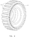
図2は、本発明の一実施形態による圧縮機ディスク107を示す斜視図であり、図2は、ブレード100のダブテイル103区間がその中に配置されているダブテイルスロット105を示す。ダブテイルスロット105の表面は、ブレード100のダブテイル103との摺動摩擦を受け、フレッチングを生じやすい。圧縮機ディスク107の表面は、浸炭区域401、および好ましくは潤滑剤被膜601(図4〜図9参照)を備える。
FIG. 2 is a perspective view of a
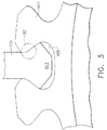
図3は、本発明の一実施形態による、圧縮機ディスク107のダブテイルスロット105内に配置されたブレード100の切断図を示す。スロット105の表面の少なくとも一部分は、ダブテイル103の表面の少なくとも一部分と摩擦接触する。ガスタービンエンジンが動作するとき、圧縮機ディスク107の回転速度の変化によってもたらされる遠心力により、ダブテイル103の表面と圧縮機ディスク107内のダブテイルスロット105の表面との間に摩擦が生じる。ダブテイル103の表面とスロット105の表面との間の摩擦係数は、好ましくは0.6より低く維持される。好ましくは、摩擦係数は、0.4より低い。より好ましくは、摩擦係数は0.2より低い。摩擦係数の低下は、浸炭により硬化された表面によって生じる。浸炭区域401(図4〜図9参照)は、処理されていないチタン含有表面よりもはるかに硬質である。さらに、潤滑剤被膜601(図6〜図9参照)を適用することによって、摩擦係数がさらに低減される。摩擦係数のさらなる低下が、潤滑剤被膜601の組成の摩擦特性によって生じる。
FIG. 3 shows a cut-away view of
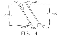
図4〜図9は、本発明による代替被膜構成を示す、図3の領域301から取った拡大断面図を示す。図4〜図9の断面図はそれぞれ、摩擦接触する、圧縮機ディスク107のダブテイルスロット105とダブテイル103を含む。圧縮機ディスク107のダブテイルスロット105の表面、およびダブテイル103の表面は、浸炭区域401および潤滑剤被膜601をその上に適用することができる、対向表面を形成する。図4〜図9は、浸炭区域401および潤滑剤被膜601の配置の代替位置を示す。潤滑剤被膜601は、ダブテイル103、圧縮機ディスク107のダブテイルスロット105、浸炭ダブテイル103、または圧縮機ディスク107の浸炭されたダブテイルスロット105上、あるいはそれらの組合せ上に堆積させることができる。任意の被膜601は、限定はされないが、グラファイト、CuNiIn、アルミニウム青銅、またはMoS2を含むことができる。図4〜図9で、圧縮機ディスク107およびダブテイル103上の被膜の間に空間を示したが、この空間は被膜の配置を説明するためのものに過ぎない。ダブテイルスロット105およびダブテイル103の各表面上の被膜システムは、互いに摩擦接触し、そこで、表面が隣接し摺動または摩擦を受ける。また、図4〜図9で示す浸炭区域401および潤滑剤被膜601の厚さは、説明のためのものに過ぎず、浸炭区域401または潤滑剤被膜601の相対的な厚さを示すものではない。
4-9 show enlarged cross-sectional views taken from
図4は、本発明の一実施形態を示す、図3の領域301から取った拡大断面図を示す。図4は、圧縮機ディスク107のダブテイルスロット105と接触する、ダブテイル103を含む。圧縮機ディスク107のダブテイルスロット105の表面403、およびダブテイル103の表面409は、それぞれ浸炭されており、浸炭区域401を備える。表面405は、圧縮機ディスク上の浸炭被膜401の表面を含み、表面407と摩擦接触する。表面407は、ダブテイル103の表面409上にある浸炭区域401の表面である。図4に示す実施形態は、ダブテイルおよび圧縮機ディスク107の両方の上に浸炭区域401が設けられており、望ましい摩擦特性を示し互いに対して摺動する硬化された摺動表面がもたらされるという利点を有する。特に、互いに対して摺動する、硬質の、耐摩耗性を有する浸炭区域401の組合せによって、低い摩擦係数がもたらされ、フレッチング耐性が高まる。
FIG. 4 shows an enlarged cross-sectional view taken from
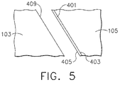
図5は、本発明の一代替実施形態を示す、図3の領域301から取った拡大断面図を示す。図5は、図4に示すような、ダブテイル103、および圧縮機ディスク107のダブテイルスロット105を含む。圧縮機ディスク107のダブテイルスロット105の表面403は浸炭されており、浸炭区域401を備える。表面405は、圧縮機ディスク107のダブテイルスロット105上にある浸炭区域401の表面を含み、ダブテイル103の表面409と摩擦接する。図5に示す実施形態は、浸炭区域401が、圧縮機ディスク107上のみを被覆するという利点を有する。したがって、浸炭区域401を圧縮機ディスク107およびブレード100の両方に適用するのに比べ、浸炭区域401の適用に必要とされる設備および労力は少ない。
FIG. 5 shows an enlarged cross-sectional view taken from
図6は、本発明の一代替実施形態を示す、図3の領域301から取った拡大断面図を示す。図6は、図4に示すような、ダブテイル103、および圧縮機ディスク107のダブテイルスロット105を含む。圧縮機ディスク107のダブテイルスロット105の表面403は浸炭されており、浸炭区域401を備える。浸炭区域401の表面405上に、潤滑剤被膜601が堆積されている。潤滑剤被膜601の表面603は、ダブテイル103の表面409と摩擦接触する。図6の実施形態は、浸炭区域401および潤滑剤被膜601が、圧縮機ディスク107のみを被覆するという利点を有する。したがって、浸炭区域401を圧縮機ディスク107のダブテイルスロットおよびエーロフォイルの両方に製作するのに比べ、浸炭区域401の製作に必要とされる設備および労力が少ない。さらに、より安価で交換が容易なブレード100が特別に処理されていないとしても、圧縮機ディスク107は、フレッチングによる損傷から保護される。浸炭区域401および潤滑剤被膜601は、ブレード100に費用を追加することなく、圧縮機ディスク107およびブレード100のシステムの保護を提供する。
FIG. 6 shows an enlarged cross-sectional view taken from
図7は、本発明の一代替実施形態を示す、図3の領域301から取った拡大断面図を示す。図7は、図4に示すような、ダブテイル103、および圧縮機ディスク107のダブテイルスロット105を含む。ブレード100のダブテイル103の表面403は浸炭されており、浸炭区域401を備える。浸炭区域401の表面407上に、潤滑剤被膜601が堆積されている。潤滑剤被膜601の表面603は、圧縮機ディスク107のダブテイルスロット105の表面403と摩擦接触する。図7の実施形態は、浸炭区域401および潤滑剤被膜601が、ブレード100のダブテイル103のみを被覆するという利点を有する。ダブテイル103のみを被覆することは、ブレード100を、本発明に従って被覆するために圧縮機ディスク107から容易に取り外すことができるという利点を有する。本発明の圧縮機ディスク107およびブレード100のシステムは、圧縮機ディスク107からブレード100を取り外すことによって、既存のガスタービンエンジン内に新しく付け替えることができ、圧縮機ディスク107をエンジンから取り外す必要がない。この実施形態では、ダブテイル103によって、圧縮機ディスク107をエンジンから取り外したり交換したりする必要なく、フレッチングに対する耐性がもたらされる。
FIG. 7 shows an enlarged cross-sectional view taken from
図8は、本発明の一代替実施形態を示す、図3の領域301から取った拡大断面図を示す。図8は、図4に示すような、ダブテイル103、および圧縮機ディスク107のダブテイルスロット105を含む。圧縮機ディスク107のダブテイルスロット105の表面403は浸炭されており、浸炭区域401を備える。ダブテイル103の表面409上に、潤滑剤被膜601が堆積されている。潤滑剤被膜601の表面603は、圧縮機ディスク107のダブテイルスロット105上にある浸炭区域401の表面405と摩擦接触する。図8の実施形態は、圧縮機ディスク107のダブテイルスロット105上に浸炭区域401が存在し、表面をフレッチングから保護するという利点を有する。さらに、ブレード100のダブテイル103は、潤滑剤被膜601で被覆される。潤滑剤被膜601は、ブレード100を圧縮機ディスク107から取り外し、ブレード100のダブテイル103を潤滑剤被膜601で被覆することによって、容易に補充することができる。本実施形態の潤滑剤被膜601によって、潤滑剤被膜601が磨耗して薄くなりまたは磨耗して完全に取れたときに、潤滑剤被膜601を容易に補充することが可能になる。
FIG. 8 shows an enlarged cross-sectional view taken from
図9は、本発明の一代替実施形態を示す、図3の領域301から取った拡大断面図を示す。図9は、図4に示すような、ダブテイル103、および圧縮機ディスク107のダブテイルスロット105を含む。圧縮機ディスク107のダブテイルスロット105の表面403は浸炭されており、浸炭区域401を備える。ブレード100のダブテイル103の表面409もまた浸炭されており、浸炭区域401を備える。潤滑剤被膜601が、ブレード100のダブテイル103および圧縮機ディスク107のダブテイルスロット105両方の上で、浸炭被膜401の表面407上に堆積されている。圧縮機ディスク107のダブテイルスロット105上の浸炭区域401上にある潤滑剤被膜601の表面603は、ブレード100のダブテイル103上の浸炭区域401上にある潤滑剤被膜601の表面603と摩擦接触する。図9に示す実施形態は、浸炭区域401および潤滑剤被膜601が、ブレード100のダブテイル103と圧縮機ディスク107上のダブテイルスロット105両方の上に存在し、フレッチングに対する追加の保護を両方の表面にもたらすという利点を有する。この実施形態では、これらの被覆は、2つの潤滑剤被膜601により、潤滑剤被膜601が磨り減ることに対するさらなる保護を有する。さらにこの実施形態によって、硬質の耐摩耗性を有する浸炭区域401の対向表面が、互いに対して摺動し、低い摩擦係数をもたらし、フレッチング耐性を向上させることが可能となり、その上に堆積された潤滑剤被膜601によって、さらなるフレッチング耐性がもたらされる。
FIG. 9 shows an enlarged cross-sectional view taken from
本発明はまた、チタンを含む金属表面を浸炭するための方法を提供する。一実施形態では、ガスタービンエンジン内で使用するための、チタン含有ブレード100または圧縮機ディスク107が浸炭される。本発明による被膜用の表面は、好ましくはチタン合金である。一実施形態では、チタン合金は、約6重量%のアルミニウム、約4重量%のバナジウム、および基本的にチタンである残部を有する、Ti−6−4チタン合金である。ブレード100で使用するのに適した他の合金は、限定はされないが、Ti−4−4−2(約4重量%のアルミニウム、約4重量%のモリブデン、約2重量%のスズ)、Ti−6−2−4−2(約6重量%のアルミニウム、約2重量%のモリブデン、約4重量%のジルコニウム、および約2重量%のスズ)、Ti−8−1−1(約8重量%のアルミニウム、約1重量%のモリブデン、および約1重量%のバナジウム)を含む。圧縮機ディスク107で使用するのに適した他の合金は、限定はされないが、Ti−17(約5重量%のアルミニウム、約4重量%のクロム、約4重量%のモリブデン、約2重量%のジルコニウム、および約2重量%のスズ)、およびTi−6−2−4−2(約6重量%のアルミニウム、約2重量%のモリブデン、約4重量%のジルコニウム、および約2重量%のスズ)を含む。浸炭区域401を有するブレード100と共に使用するための圧縮機ディスク107の製作に適した他の合金としては、限定はされないが、INCONEL(登録商標)718、R−95、またはR−88などの、ニッケルベースの合金を含む。INCONEL(登録商標)は、ウェストバージニア州ハンティントンのHuntington Alloys Corporation社が所有する、連邦登録商標である。INCONEL(登録商標)718の組成は、当技術分野ではよく知られており、これは、約18重量%のクロム、約19重量%の鉄、約5重量%のニオビウムおよびタンタル、約3重量%のモリブデン、約0.9重量%のチタン、約0.5重量%のアルミニウム、約0.05重量%の炭素、約0.009重量%のボロン、最大約1重量%のコバルト、最大約0.35重量%のマンガン、最大約0.35重量%のシリコン、最大約0.1重量%の銅、およびニッケルである残部を含む、ニッケルベースの超合金の呼称である。R95は、約8%のコバルト、約13%のクロム、約3.5%のモリブデン、約3.5%のタングステン、約3.5%のアルミニウム、約2.5%のチタン、約3.5%のニオビウム、約0.03%のボロン、約0.03%の炭素、約0.03%のジルコニウム、約0.01%以下のバナジウム、約0.3%以下のハフニウム、約0.01%以下のイットリウム、および基本的にニッケルである残部を有する組成を含む。R−88は、約13%のコバルト、約16%のクロム、約4%のモリブデン、約4%のタングステン、約2%のアルミニウム、約3.7%のチタン、約0.75%のニオビウム、約0.4%のジルコニウム、約0.06%の炭素、約0.010%のボロンを有し、基本的にニッケルである残部を有する組成を含む。
The present invention also provides a method for carburizing a metal surface comprising titanium. In one embodiment, the titanium-containing
本発明によれば、チタンを含む金属表面は、安定した炭化物を制御され予め選択された距離で表面の下に形成するために、制御された条件下で、メタン、プロパン、エチレンガス、アセチレン、二酸化炭素、一酸化炭素、またはそれらの組合せなどの炭素含有ガスを浸炭剤として使用して浸炭される。炭化物は、炭化チタン、炭化バナジウム、および、チタン−バナジウム炭化物複合体を含めてそれらの混合物を含むことができる。これらのガスは、組み合わせて混合させることができ、または、浸炭ガスの反応性を制御するために、アルゴン、ヘリウム、または水素など、非反応性のガスをこれらのガスに加えることができる。表面中に形成された炭化チタンによって表面が硬化され、摩擦係数が低下し、フレッチングが減少する。チタンマトリックス中の格子間炭素の濃度および/または存在もまた、プロセスにおける制御要素となり得る。 In accordance with the present invention, a titanium-containing metal surface is formed under controlled conditions such as methane, propane, ethylene gas, acetylene, to form a stable carbide below the surface at a controlled and preselected distance. Carburized using a carbon-containing gas such as carbon dioxide, carbon monoxide, or a combination thereof as a carburizing agent. The carbide can include titanium carbide, vanadium carbide, and mixtures thereof including titanium-vanadium carbide composites. These gases can be mixed and mixed, or non-reactive gases such as argon, helium, or hydrogen can be added to these gases to control the reactivity of the carburizing gas. The surface is hardened by titanium carbide formed in the surface, the friction coefficient is lowered, and fretting is reduced. The concentration and / or presence of interstitial carbon in the titanium matrix can also be a controlling factor in the process.
本発明は、製品の表面を清浄化する段階を含むことができる。製品表面の清浄化は、基板表面から部分的または実質的にすべての酸化物を除去すること、および、浸炭されるべき酸化物が表面から再形成されることを防止することを伴う。浸炭されるべき表面には、好ましくは酸化物が存在しない。酸化物の除去は、基板表面を損傷せずまたはそうでなくても基板表面に悪影響を与えない、機械的または化学的な方法によって実現することができる。機械的または化学的な酸化物除去方法は、限定はされないがグリットブラストまたは化学エッチングを含めて、当技術分野で知られるいかなる酸化物除去方法でもよい。そのような清浄化の後、酸化物の形成を回避しながら、表面を適当な溶液で清浄化することができる。酸化物は回避されるべきであるが、表面のいくつかの部分が浸炭されるのを防ぐために、これらの部分をマスクすることが望ましいことがある。これは、チタン含有表面が他のチタン含有表面と接触しない、かつ/またはフレッチングもしくは磨耗を受けにくいなど、いくつかの理由のうちの1つのために望ましいことがある。したがって、必要に応じて、浸炭を必要としない部分をマスクすることができる。 The present invention can include the step of cleaning the surface of the product. Cleaning the product surface involves removing partial or substantially all oxide from the substrate surface and preventing the oxide to be carburized from being re-formed from the surface. The surface to be carburized is preferably free of oxides. Oxide removal can be accomplished by mechanical or chemical methods that do not damage the substrate surface or otherwise do not adversely affect the substrate surface. The mechanical or chemical oxide removal method may be any oxide removal method known in the art, including but not limited to grit blasting or chemical etching. After such cleaning, the surface can be cleaned with a suitable solution while avoiding oxide formation. Oxides should be avoided, but it may be desirable to mask some parts of the surface to prevent carburization of some parts. This may be desirable for one of several reasons, such as the titanium-containing surface is not in contact with other titanium-containing surfaces and / or is not susceptible to fretting or wear. Therefore, the part which does not require carburizing can be masked as needed.
圧縮機ディスク107および/またはブレード100の表面の部分にマスクを設けることができるが、圧縮機ディスク107および/またはブレード100全体を浸炭することによって、圧縮機ディスク107およびブレード100に所望の表面特性をもたらすことができる。たとえば、浸炭区域401を有するブレード100のエーロフォイル101部分は、表面にある炭化物および/または格子間炭素の存在により、耐腐食性とすることができる。耐腐食性は、エーロフォイル101および圧縮機ディスクが、水、および/または塩などの腐食促進物質を含む空気と接触する可能性があるため、エーロフォイル101および圧縮機ディスク107にとって望ましい。さらに、圧縮機ディスク107および/またはブレード100全体の浸炭によって、硬化され耐摩耗性を有する浸炭区域401による侵食に対する保護を、圧縮機ディスク107およびブレード100にもたらすことができる。耐侵食性は、砂または埃など研磨物質を含む空気と接触することから、たとえばエーロフォイル101および圧縮機ディスク107にとって望ましい。したがって、本発明の方法は有利には、圧縮機ディスク107および/またはブレード100全体を被覆するために利用することができる。
Although a portion of the surface of the
清浄化された製品は、次いで浸炭プロセスの実施に適当な炉内に配置される。適当な炉は、真空炉、または制御された雰囲気を維持することができる炉を含む。炉は、チタン中への炭素の拡散を可能にするのに十分な温度、かつ538℃(1000°F)未満に加熱することができる。好ましくは、炉は400℃(750°F)に加熱される。チタン含有製品が浸炭温度に到達した後、酸素の導入を防止する何らかの方法によって浸炭ガスを炉内に導入することができる。さらに、浸炭ガスの導入は、炭素含有ガスの濃度を変えることができるようなものであるべきである。浸炭温度までの加熱中および浸炭中は製品表面の酸化および浸炭ガスと酸素の反応が防止されなければならないので、制御された雰囲気を維持する場合、その雰囲気は非酸化雰囲気でなくてはならない。浸炭温度に到達すると、浸炭ガス、すなわちメタン、プロパン、エチレン、またはアセチレンが、炉内に導入される。これらの浸炭ガスは、浸炭温度より低い温度で、水素と共に、または水素を徐々に置き換えるように導入することができるが、過度にすすを形成することになる温度または体積で加えるべきではない。浸炭ガスは、炭素が拡散され、炭化チタンを有する層中に形成され、かつ/または炭素が格子間に拡散されるよう、所望の浸炭に十分な炭素が製品表面上に存在することが保証されるように供給される。炭化物および/または格子間炭素によって、表面の硬度が増大され、フレッチングが低減される。表面の硬度が増大するので、チタン含有表面間の局所的な付着の発生が減少する。局所的な付着の減少によって、フレッチング疲労および磨耗に対するより高い耐性がもたらされる。炭化物層形成の深さが限定されるように、浸炭プロセスの炭素含有ガス中における炭素の持続時間、温度、および濃度を制御することができる。相中に存在する炭素の量は、別のチタン含有表面と接触するときの、チタン含有表面のフレッチングに対する脆弱性を低減させるのに十分である。浸炭区域401中に存在する炭素の量は、1000°Fを超える温度などの高温で浸炭された、従来の浸炭表面中に存在する炭素の量よりも多い。
The cleaned product is then placed in a furnace suitable for carrying out the carburizing process. Suitable furnaces include vacuum furnaces or furnaces that can maintain a controlled atmosphere. The furnace can be heated to a temperature sufficient to allow diffusion of carbon into the titanium and below 538 ° C. (1000 ° F.). Preferably, the furnace is heated to 400 ° C. (750 ° F.). After the titanium-containing product reaches the carburizing temperature, the carburizing gas can be introduced into the furnace by any method that prevents the introduction of oxygen. Furthermore, the introduction of carburizing gas should be such that the concentration of the carbon-containing gas can be changed. During heating to the carburizing temperature and during carburizing, oxidation of the product surface and reaction of the carburizing gas and oxygen must be prevented, so if a controlled atmosphere is maintained, the atmosphere must be a non-oxidizing atmosphere. When the carburizing temperature is reached, carburizing gas, methane, propane, ethylene, or acetylene, is introduced into the furnace. These carburizing gases can be introduced at a temperature below the carburizing temperature, with hydrogen, or to gradually replace the hydrogen, but should not be added at a temperature or volume that would form excessive soot. The carburizing gas ensures that there is sufficient carbon on the product surface for the desired carburization so that carbon is diffused and formed in a layer with titanium carbide and / or carbon is diffused between the lattices. To be supplied. Carbides and / or interstitial carbon increase surface hardness and reduce fretting. As the surface hardness increases, the occurrence of local adhesion between titanium-containing surfaces decreases. Reduced local adhesion results in higher resistance to fretting fatigue and wear. The duration, temperature, and concentration of carbon in the carbon-containing gas of the carburization process can be controlled so that the depth of carbide layer formation is limited. The amount of carbon present in the phase is sufficient to reduce the vulnerability of the titanium-containing surface to fretting when in contact with another titanium-containing surface. The amount of carbon present in the carburized
浸炭は、所望の浸炭深さに到達するまで続行され、到達された時点で、不活性ガスを炉内に導入することによって操作を停止させる。浸炭深さは、温度、時間および濃度に依存しており、結果的に得られる深さは、物質移動の法則、特に、フィックの第1および第2拡散法則に従うことがある。炭素が拡散する温度よりも製品の表面温度が低くなると、浸炭が止まる。浸炭深さは、製品が炭素含有ガスに暴露される時間、炭素含有ガス中の炭素濃度、および製品の温度を含めて、様々な要因に基づいて変わる。浸炭被膜401のための好ましい深さは、0.0254cm(0.01インチ)以下である。より好ましくは、0.00254cm(0.001インチ)以下である。本発明による浸炭プロセスは、所望の浸炭被覆401深さを達成するために、約1500時間以下の時間で行われる。好ましくは、浸炭は約1000時間以下の時間で行われる。
Carburization is continued until the desired carburization depth is reached, at which point the operation is stopped by introducing an inert gas into the furnace. The carburization depth depends on temperature, time and concentration, and the resulting depth may obey mass transfer laws, in particular Fick's first and second diffusion laws. Carburization stops when the surface temperature of the product is lower than the temperature at which carbon diffuses. The carburization depth varies based on a variety of factors, including the time the product is exposed to the carbon-containing gas, the carbon concentration in the carbon-containing gas, and the temperature of the product. The preferred depth for the carburized
浸炭プロセスは、浸炭ガスのチャンバをパージすることによって完了する。これは、浸炭ガスの流れを停止し、不活性ガス、すなわち窒素または水素をチャンバ内に導入することによって実現することができる。これはまた、製品を冷却する働きをする。表面上に存在するいかなるマスクも除去することができる。 The carburizing process is completed by purging the carburizing gas chamber. This can be achieved by stopping the flow of the carburizing gas and introducing an inert gas, ie nitrogen or hydrogen, into the chamber. This also serves to cool the product. Any mask present on the surface can be removed.
当業者には認識されるように、いくつかの操作パラメータを変えることができ、したがって、所望の炭化物層厚さが制御されるように、それらのパラメータを制御しなければならない。それらのパラメータは、限定はされないが、ガス分圧を決定するガス流量、温度、炉のタイプ、作業区域のサイズ、作業装填物、および時間を含む。 As will be appreciated by those skilled in the art, several operating parameters can be varied and therefore must be controlled such that the desired carbide layer thickness is controlled. These parameters include, but are not limited to, the gas flow rate that determines the gas partial pressure, temperature, furnace type, work area size, work load, and time.
加工および冷却の後、複数の製品を含むことがある作業装填物を、作業区域から取り出すことができる。いかなる任意のマスキングも、随意の潤滑剤被膜601を適用する前または後に除去することができる。マスキングは、化学的ストリッピング、ブラスティングなどの機械的手段、またはマスキング材料に適合するその他の知られた方法など、基板表面に悪影響を及ぼさないいかなる適当な方法によって除去することもできる。
After processing and cooling, a work load that may contain multiple products can be removed from the work area. Any optional masking can be removed before or after the
チタンを含む圧縮機ディスク107およびエーロフォイル101は、本発明の方法で使用するのに特に適している。浸炭された圧縮機ディスク107、および/または潤滑剤被膜601で被覆されたダブテイル103は、望ましい摩擦特性をもたらす。本発明は、比較的硬質の浸炭区域401と、磨耗しやすい表面上に配置することができる比較的軟質の滑らかな潤滑剤被膜601との組合せを利用する。適当な表面は、ガスタービンエンジンの圧縮機内の構成要素の表面を含む。浸炭区域401によって、圧縮機ディスク107とブレード100の間の摩擦係数が低下する。潤滑剤被膜601によってさらに、圧縮機ディスク107とブレード100の間の摩擦係数が低下し、表面間の付着が減少し、それによってフレッチングが減少する。
好ましくは、摩擦係数は、ダブテイルスロット105およびダブテイル103の磨耗システム内で、0.6以下、好ましくは0.4以下に維持される。より好ましくは、摩擦係数は、ダブテイルスロット105およびダブテイル103の磨耗システム内で、0.2以下に維持される。摩擦係数は、互いに摩擦し合う2つの面の間で測定される。図4〜図9に示す本発明の実施形態で、ブレード100のダブテイル103と圧縮機ディスク107のダブテイルスロット105の間の摩擦係数は、約0.6以下である。圧縮機ディスク107およびブレード100は、限定はされないが、金属および金属合金を含めていかなる適当な材料で製作することもできる。好ましい材料は、チタンおよびその合金を含む。その他の適当な合金は、限定はされないが、INCONEL(登録商標)718など、ニッケルベースの合金を含む。さらに、圧縮機ディスク107は、R−95およびR−88など、ニッケルベースの合金で製作することができる。
Preferably, the coefficient of friction is maintained below 0.6, preferably below 0.4, within the wear system of the
本発明の別の実施形態では、被膜システムにさらなる望ましい特性をもたらすために、潤滑剤被膜601に添加剤を含むことができる。さらなる添加剤は、より高い滑性、潤滑剤被膜601の表面に対するより高い付着度、または被膜のより高い均質性などの、望ましい特性を組成物にもたらす添加剤である。さらなる適当な添加剤は、限定はされないが、ポリテトラフルオロエチレン、定着剤、分散剤、およびそれらの組合せを含む。さらなる添加剤の例として、グラファイト、硫化モリブデン、二セレン化モリブデン、および銅が挙げられる。
In another embodiment of the present invention, an additive may be included in the
本発明での用途が見出される代替システムは、アクチュエータ機構、エンジン内の他の部分のダブテイル表面、および低い摩擦係数が必要とされるまたは望ましいその他の表面を含めて、ガスタービンエンジンのチタン含有構成要素を含む。特に、本発明は、1つのチタン含有表面が第2のチタン含有表面に対して摺動する応用例を含めて、フレッチングが生じやすい応用例における用途が見出される。摩擦接触する表面の片方または両方を処理することによって、摩擦係数が低下し、フレッチング疲労および磨耗も低減される。 Alternative systems that find use in the present invention include titanium-containing configurations of gas turbine engines, including actuator mechanisms, dovetail surfaces of other parts of the engine, and other surfaces where a low coefficient of friction is required or desirable. Contains elements. In particular, the present invention finds use in applications where fretting is likely to occur, including applications where one titanium-containing surface slides relative to a second titanium-containing surface. By treating one or both of the surfaces in frictional contact, the coefficient of friction is reduced and fretting fatigue and wear are also reduced.
本発明を好ましい実施形態を参照しながら説明してきたが、本発明の範囲から逸脱することなく、様々な変更を加えることができ、同等物でその要素を置き換えることができることが、当業者には理解されるであろう。さらに、特定の状況または材料を本発明の教示に適合させるために、その基本的な範囲から逸脱することなく多くの修正を加えることができる。したがって、本発明は、本発明を実施するために意図された最良の形態として開示した特定の実施形態に限定されるものではなく、添付の特許請求の範囲の範囲に包含されるすべての実施形態を含むものである。 Although the present invention has been described with reference to preferred embodiments, workers skilled in the art will recognize that various modifications can be made and the elements replaced with equivalents without departing from the scope of the invention. Will be understood. In addition, many modifications may be made to adapt a particular situation or material to the teachings of the invention without departing from the basic scope thereof. Accordingly, the invention is not limited to the specific embodiments disclosed as the best mode contemplated for carrying out the invention, but all embodiments encompassed within the scope of the appended claims. Is included.
100 ブレード
101 エーロフォイル
103 ダブテイル
105 ダブテイルスロット
107 圧縮機ディスク
301 領域
401 浸炭区域
403 表面
405 表面
407 表面
409 表面
601 潤滑剤被膜
603 表面
100
Claims (8)
チタン含有表面を有する基板を準備する段階と、
前記チタン中に炭素を拡散させるのに十分な高さで且つ538℃未満の温度に前記基板を加熱する段階と、
前記基板中に炭素を拡散させて1種以上の炭化物及び格子間炭素を含む表面層を形成するのに十分な時間、炭素含有ガスに前記表面を接触させる段階(ただし、プラズマ浸炭処理を含むものを除く。)と
を含む方法。 A method for surface treating a titanium-containing substrate,
Preparing a substrate having a titanium-containing surface,
Heating the substrate to a temperature high enough to diffuse carbon into the titanium and less than 538 ° C .;
The period of time sufficient to form a surface layer containing carbon between one or more carbides and the lattice by diffusing carbon into the substrate, the step of contacting the surface with carbon-containing gas (including a plasma carburizing Excluding things) and
The method comprising.
Applications Claiming Priority (4)
| Application Number | Priority Date | Filing Date | Title |
|---|---|---|---|
| US69475905P | 2005-06-28 | 2005-06-28 | |
| US60/694,759 | 2005-06-28 | ||
| US11/247,874 | 2005-10-11 | ||
| US11/247,874 US20060289088A1 (en) | 2005-06-28 | 2005-10-11 | Titanium treatment to minimize fretting |
Publications (3)
| Publication Number | Publication Date |
|---|---|
| JP2007009329A JP2007009329A (en) | 2007-01-18 |
| JP2007009329A5 JP2007009329A5 (en) | 2009-08-13 |
| JP5000212B2 true JP5000212B2 (en) | 2012-08-15 |
Family
ID=37075834
Family Applications (1)
| Application Number | Title | Priority Date | Filing Date |
|---|---|---|---|
| JP2006177521A Expired - Fee Related JP5000212B2 (en) | 2005-06-28 | 2006-06-28 | Titanium treatment method to minimize fretting |
Country Status (3)
| Country | Link |
|---|---|
| US (1) | US20060289088A1 (en) |
| EP (1) | EP1739203A1 (en) |
| JP (1) | JP5000212B2 (en) |
Families Citing this family (8)
| Publication number | Priority date | Publication date | Assignee | Title |
|---|---|---|---|---|
| JP4024554B2 (en) * | 2001-02-27 | 2007-12-19 | 松下電器産業株式会社 | Fuel cell power generation system |
| US7506440B2 (en) * | 2005-06-28 | 2009-03-24 | General Electric Company | Titanium treatment to minimize fretting |
| US8608592B2 (en) | 2007-05-16 | 2013-12-17 | Taylor Made Golf Company, Inc. | Coated golf club head/component |
| WO2010094368A1 (en) * | 2009-02-23 | 2010-08-26 | BLüCHER GMBH | Textile material having increased mechanical strength, in particular having increased resistance to piercing or shooting |
| US20130261034A1 (en) * | 2009-07-17 | 2013-10-03 | General Electric Company | Coating for turbomachinery |
| CN102703852B (en) * | 2012-06-15 | 2014-03-12 | 西北有色金属研究院 | Method for composite hydrogen-free oxygen-carburizing on surface of two-phase titanium alloy |
| US20160003067A1 (en) * | 2013-03-07 | 2016-01-07 | United Technologies Corporation | Aluminum Fan Blades with Root Wear Mitigation |
| FR3005433B1 (en) * | 2013-05-07 | 2015-06-26 | Eads Europ Aeronautic Defence | MECHANICAL ASSEMBLY WITH IMPROVED FATIGUE-FRICTION PROTECTION DURING MICRO-DISPLACEMENTS |
Family Cites Families (23)
| Publication number | Priority date | Publication date | Assignee | Title |
|---|---|---|---|---|
| US3628921A (en) * | 1969-08-18 | 1971-12-21 | Parker Pen Co | Corrosion resistant binder for tungsten carbide materials and titanium carbide materials |
| DE2929634C3 (en) * | 1979-07-21 | 1982-05-19 | MTU Motoren- und Turbinen-Union München GmbH, 8000 München | Process for the production of turbo blades made of titanium or titanium-based alloy with a hard surface |
| US4943485A (en) * | 1981-11-27 | 1990-07-24 | S R I International | Process for applying hard coatings and the like to metals and resulting product |
| US4704336A (en) * | 1984-03-12 | 1987-11-03 | General Electric Company | Solid particle erosion resistant coating utilizing titanium carbide |
| JPS61291959A (en) * | 1985-06-20 | 1986-12-22 | Mitsubishi Heavy Ind Ltd | Production of titanium alloy valve of engine |
| US5074970A (en) * | 1989-07-03 | 1991-12-24 | Kostas Routsis | Method for applying an abrasive layer to titanium alloy compressor airfoils |
| US5315822A (en) * | 1991-12-20 | 1994-05-31 | United Technologies Corporation | Gas turbine elements rearing coke inhibiting coatings of titanium compounds |
| JP3149577B2 (en) * | 1992-10-21 | 2001-03-26 | 大同特殊鋼株式会社 | Surface treatment method of Ti-Al intermetallic compound |
| JPH0790541A (en) * | 1993-09-13 | 1995-04-04 | Demutetsuku Kk | Mixed gas penetration modifying method and device therefor |
| EP0697503B1 (en) * | 1994-08-17 | 1998-06-17 | Asea Brown Boveri Ag | Method for the construction of a turbine blade from an (alpha-beta)-Titanium-base alloy |
| US5687900A (en) * | 1995-03-28 | 1997-11-18 | Mcdonnell Douglas Corporation | Structural panel having a predetermined shape and an associated method for superplastically forming and diffusion bonding the structural panel |
| US5910376A (en) * | 1996-12-31 | 1999-06-08 | General Electric Company | Hardfacing of gamma titanium aluminides |
| US5891267A (en) * | 1997-01-16 | 1999-04-06 | General Electric Company | Thermal barrier coating system and method therefor |
| US6190133B1 (en) * | 1998-08-14 | 2001-02-20 | Allison Engine Company | High stiffness airoil and method of manufacture |
| GB9821748D0 (en) * | 1998-10-07 | 1998-12-02 | Rolls Royce Plc | A titanium article having a protective coating and a method of applying a protective coating to a titanium article |
| GB9824611D0 (en) * | 1998-11-11 | 1999-01-06 | Rolls Royce Plc | A beta titanium alloy |
| JP4185633B2 (en) * | 1999-08-10 | 2008-11-26 | フジオーゼックス株式会社 | Titanium alloy engine valve and surface treatment method thereof |
| US7291229B2 (en) * | 2000-07-12 | 2007-11-06 | Osaka Prefecture | Method of surface treatment of titanium metal |
| JP4603198B2 (en) * | 2001-06-14 | 2010-12-22 | 株式会社田中 | Method for improving fatigue characteristics of titanium alloy parts and titanium alloy parts using the same |
| JP2003041359A (en) * | 2001-07-30 | 2003-02-13 | Tanaka:Kk | Method for improving fatigue property of titanium alloy component, and titanium alloy component using the same |
| JP3936892B2 (en) * | 2002-06-07 | 2007-06-27 | 株式会社エスディーシー | Plasma carburizing method and apparatus |
| DE10305912B4 (en) * | 2003-02-13 | 2014-01-30 | Alstom Technology Ltd. | Hybrid blade for thermal turbomachinery |
| JP2005312619A (en) * | 2004-04-28 | 2005-11-10 | Bridgestone Sports Co Ltd | Golf club head |
-
2005
- 2005-10-11 US US11/247,874 patent/US20060289088A1/en not_active Abandoned
-
2006
- 2006-06-26 EP EP06253302A patent/EP1739203A1/en not_active Ceased
- 2006-06-28 JP JP2006177521A patent/JP5000212B2/en not_active Expired - Fee Related
Also Published As
| Publication number | Publication date |
|---|---|
| US20060289088A1 (en) | 2006-12-28 |
| EP1739203A1 (en) | 2007-01-03 |
| JP2007009329A (en) | 2007-01-18 |
Similar Documents
| Publication | Publication Date | Title |
|---|---|---|
| JP5000212B2 (en) | Titanium treatment method to minimize fretting | |
| JP5122768B2 (en) | Titanium treatment to minimize fretting | |
| US6605160B2 (en) | Repair of coatings and surfaces using reactive metals coating processes | |
| JP4322980B2 (en) | Gas turbine engine sealing mechanism | |
| EP1512839B1 (en) | Method for creating an aluminide or chromide coating of turbine engine rotor component | |
| US20050129511A1 (en) | Turbine blade tip with optimized abrasive | |
| Leyens et al. | Oxide scale formation on an MCrAlY coating in various H2-H2O atmospheres | |
| RU2436866C2 (en) | Heat resistant component | |
| CA2441490C (en) | Method for vapor phase aluminiding of a gas turbine blade partially masked with a masking enclosure | |
| US6532657B1 (en) | Pre-service oxidation of gas turbine disks and seals | |
| JP2007298035A (en) | Coating for gas turbine engine component, seal assembly, and coating method | |
| KR20160111410A (en) | Methods of applying chromium diffusion coatings onto selective regions of a component | |
| JP5246745B2 (en) | Substrate stabilization method for diffusion aluminide coated nickel base superalloy | |
| JP5426088B2 (en) | Carburizing process for stabilizing nickel-base superalloys. | |
| Garg et al. | Low‐Temperature Chemical Vapor Deposition Tungsten Carbide Coatings for Wear/Erosion Resistance | |
| US20060057416A1 (en) | Article having a surface protected by a silicon-containing diffusion coating | |
| JP2005120478A (en) | Region-selective vapor-phase aluminizing method | |
| EP2781561B1 (en) | Treated coated article and process of treating a coated article | |
| JP2007009316A (en) | Abrasion-resistant steel parts and manufacturing method therefor | |
| JP2008275035A (en) | Steam valve for steam turbine | |
| EP3153486A1 (en) | Method for coating removal | |
| EP1522607B1 (en) | Method for fabricating a coated superalloy stabilized against the formation of secondary reaction zone | |
| JP4494995B2 (en) | Metal surface treatment method | |
| Kempster et al. | A novel method for refurbishing used hot section gas turbine blades | |
| EP1076108A1 (en) | Process for treating the surface of a component, made from a Ni based superalloy, to be coated |
Legal Events
| Date | Code | Title | Description |
|---|---|---|---|
| A521 | Written amendment |
Free format text: JAPANESE INTERMEDIATE CODE: A523 Effective date: 20090625 |
|
| A621 | Written request for application examination |
Free format text: JAPANESE INTERMEDIATE CODE: A621 Effective date: 20090625 |
|
| RD04 | Notification of resignation of power of attorney |
Free format text: JAPANESE INTERMEDIATE CODE: A7424 Effective date: 20090625 |
|
| A977 | Report on retrieval |
Free format text: JAPANESE INTERMEDIATE CODE: A971007 Effective date: 20110915 |
|
| A131 | Notification of reasons for refusal |
Free format text: JAPANESE INTERMEDIATE CODE: A131 Effective date: 20110927 |
|
| A601 | Written request for extension of time |
Free format text: JAPANESE INTERMEDIATE CODE: A601 Effective date: 20111222 |
|
| A602 | Written permission of extension of time |
Free format text: JAPANESE INTERMEDIATE CODE: A602 Effective date: 20111228 |
|
| A521 | Written amendment |
Free format text: JAPANESE INTERMEDIATE CODE: A523 Effective date: 20120327 |
|
| TRDD | Decision of grant or rejection written | ||
| A01 | Written decision to grant a patent or to grant a registration (utility model) |
Free format text: JAPANESE INTERMEDIATE CODE: A01 Effective date: 20120417 |
|
| A01 | Written decision to grant a patent or to grant a registration (utility model) |
Free format text: JAPANESE INTERMEDIATE CODE: A01 |
|
| A61 | First payment of annual fees (during grant procedure) |
Free format text: JAPANESE INTERMEDIATE CODE: A61 Effective date: 20120516 |
|
| R150 | Certificate of patent or registration of utility model |
Free format text: JAPANESE INTERMEDIATE CODE: R150 |
|
| FPAY | Renewal fee payment (event date is renewal date of database) |
Free format text: PAYMENT UNTIL: 20150525 Year of fee payment: 3 |
|
| R250 | Receipt of annual fees |
Free format text: JAPANESE INTERMEDIATE CODE: R250 |
|
| LAPS | Cancellation because of no payment of annual fees |