JP4999643B2 - Imaging device - Google Patents
Imaging device Download PDFInfo
- Publication number
- JP4999643B2 JP4999643B2 JP2007286474A JP2007286474A JP4999643B2 JP 4999643 B2 JP4999643 B2 JP 4999643B2 JP 2007286474 A JP2007286474 A JP 2007286474A JP 2007286474 A JP2007286474 A JP 2007286474A JP 4999643 B2 JP4999643 B2 JP 4999643B2
- Authority
- JP
- Japan
- Prior art keywords
- display
- state
- liquid crystal
- video light
- brightness
- Prior art date
- Legal status (The legal status is an assumption and is not a legal conclusion. Google has not performed a legal analysis and makes no representation as to the accuracy of the status listed.)
- Expired - Fee Related
Links
Images


Landscapes
- Stroboscope Apparatuses (AREA)
- Studio Devices (AREA)
Description
本発明は、被写体を撮像する撮像装置に関する。 The present invention relates to an imaging equipment for imaging a subject.
従来、撮像装置である各種カメラにおいて、被写体に対する照明光源として、内蔵ライトや、カメラ本体に対して着脱自在に設けられた外付けライトである外部照明等が一般的に用いられている。また、液晶パネルを全白にしてその光を被写体に向けることで、ビデオライトとして使用することが知られている(特許文献1参照)。 2. Description of the Related Art Conventionally, in various cameras that are imaging devices, a built-in light, an external light that is an external light provided detachably with respect to a camera body, or the like is generally used as an illumination light source for a subject. In addition, it is known that the liquid crystal panel is used as a video light by making the liquid crystal panel completely white and directing the light toward the subject (see Patent Document 1).
図6は従来の撮像装置の一例としてビデオカメラの外観を示す斜視図である。ビデオカメラ110は、カメラ本体112の前部にレンズ114、その後部にカラービューファインダ116、その側部に液晶モニタ118等を有する。
FIG. 6 is a perspective view showing an appearance of a video camera as an example of a conventional imaging apparatus. The
液晶モニタ118は、ヒンジ部120によりカメラ本体112に対して回転自在に取り付けられている。対面撮影の場合、図6に示すように、液晶モニタ118を被写体に向けることにより、液晶モニタ118とカラービューファインダ116が同時点灯する。従って、写されている人がどのように撮影されているかを見ながら撮影することができる。
The
液晶モニタ118は、フレーム122に取り付けられた液晶パネル124、およびこの液晶パネル124の後部に配置されているバックライト126(図7参照)を有する。これにより、液晶パネル124は発光形の表示器となっている。
The
液晶パネル124は、一般に全白(透過率が最大の状態)にすると、液晶パネル124から出てくる光量が最大となり、あたかもビデオライトを照射しているときと同じ状態となる。この現象を積極的に利用することにより、このビデオカメラは、液晶モニタ118をビデオライトとして機能させるものである。
In general, when the
図7は主に液晶モニタ118の制御に係る部分の制御回路の構成を示す図である。この制御回路はカメラ本体112の内部に設けられる。また、この制御回路は、LCDドライブ回路101、制御マイコン102、撮影モード検出回路103、切替スイッチ104、電源回路105、発振回路106、インバータトランス107等を有する。この回路構成は、周知のものであり、切替スイッチ104により液晶モニタ118を全白に切り替え、ビデオライトとして利用する点に特徴を有する。
FIG. 7 is a diagram showing a configuration of a control circuit of a part mainly related to the control of the
すなわち、切替スイッチ104をオンにすることにより、撮影モード検出回路103から制御マイコン102を通じてLCDドライブ回路101に信号が入力され、液晶パネル124を全白にする。これにより、液晶パネル124からの光量が最大となり、液晶パネル124は被写体を照射し、ビデオライトの機能を果たす。また、全白にした場合、液晶パネル124の光量をより増大させるため、バックライト126の輝度を上げる。切替スイッチ104のオンで制御マイコン102から電源回路105に制御信号が入力され、この電源回路105の電圧を増加(アップ)させる。これにより、バックライト126の照度を上げることができる。なお、バックライト126としては、直下形蛍光管、導光板付き蛍光管、導光板付きLED等、種々の方式のものがあり、いずれの方式のものでも使用可能である。
しかしながら、上記従来の撮像装置では、液晶パネルを全白(ビデオライト)に切り替えた場合、常にバックライトの輝度を上げているため、消費電力が増大し、バッテリの消費が早くなる。 However, in the above conventional imaging device, when the liquid crystal panel is switched to all white (video light), the luminance of the backlight is constantly increased, so that power consumption increases and battery consumption is accelerated.
また、撮影者が暗い場所で液晶モニタを撮影者側に向けた状態でビデオライトに切り替えた場合、バックライトの輝度が上がった状態で液晶パネルが急に全白画面に切り替わるため、眩しさを感じるおそれがあった。 In addition, when the photographer switches to a video light with the LCD monitor facing the photographer in a dark place, the LCD panel suddenly switches to an all-white screen with the backlight brightness increased. I could feel it.
そこで、本発明は、こうした従来の問題点を解決するものであり、ビデオライトモード時の消費電力の削減を図ることができる撮像装置を提供することを目的としている。また、本発明は、撮影者側に向けた状態でビデオライトに切り替えた場合でも、眩しさを感じるおそれを無くすことができる撮像装置を提供することを他の目的としている。 The present invention is intended to solve such conventional problems, and its object is to provide an imaging equipment which makes it possible to reduce the power consumption during video light mode. Further, the present invention, even when switching to the video light in a state toward the photographer side, and the other object is to provide an imaging equipment can be eliminated the risk to feel glare.
上記目的を達成するために、本発明の撮像装置は、被写体を撮像する撮像装置であって、前記被写体側に反転自在に設けられ、前記撮像された被写体の映像表示あるいは全白表示を行う表示手段と、前記表示手段が前記被写体側に向いている反転状態を検出する状態検出手段と、前記表示手段をビデオライトとして使用するためのビデオライトモードを選択する選択手段と、前記ビデオライトモードが選択された場合、前記表示手段を全白表示に切り替える表示制御手段と、前記表示手段の輝度を調節する輝度調節手段と、前記表示手段が前記被写体側に向いていない、前記反転状態以外の状態が検出された場合、前記輝度調節手段を制御し、前記全白表示が行われている前記表示手段の輝度を、前記反転状態の場合と比べ、低下させる輝度制御手段とを備えたことを特徴とする。 In order to achieve the above object, an image pickup apparatus according to the present invention is an image pickup apparatus for picking up an image of a subject, and is provided on the subject side so as to be reversible, and a display for performing image display or all white display of the imaged subject. Means for detecting a reverse state in which the display means is directed to the subject side, selection means for selecting a video light mode for using the display means as a video light, and the video light mode. When selected, a display control means for switching the display means to all white display, a brightness adjusting means for adjusting the brightness of the display means, and a state other than the inverted state, in which the display means is not directed to the subject side Is detected, the brightness adjusting means is controlled to reduce the brightness of the display means in which the all white display is performed compared to the case of the inversion state. Characterized in that a control means.
本発明の撮像装置は、被写体を撮像する撮像装置であって、前記被写体側あるいは撮影者側に反転自在に設けられ、前記撮像された被写体の映像表示あるいは全白表示を行う表示手段と、前記表示手段が前記撮影者側に向いている正転状態あるいは前記被写体側に向いている反転状態を検出する状態検出手段と、前記表示手段をビデオライトとして使用するためのビデオライトモードを選択する選択手段と、前記ビデオライトモードが選択された場合、前記表示手段を全白表示に切り替える表示制御手段と、前記表示手段の輝度を調節する輝度調節手段と、前記表示手段が前記撮影者側に向いている正転状態が検出された場合、前記輝度調節手段を制御し、前記全白表示が行われている前記表示手段の輝度を、前記反転状態の場合と比べ、低下させる輝度制御手段とを備えたことを特徴とする。 The imaging apparatus of the present invention is an imaging apparatus that images a subject, and is provided on the subject side or the photographer side so as to be reversible, and a display unit that performs video display or all-white display of the captured subject, Selection for selecting a state detection means for detecting a normal rotation state in which the display means is directed to the photographer side or a reverse state in which the display means is directed to the subject side, and a video light mode for using the display means as a video light Means, when the video light mode is selected, display control means for switching the display means to all white display, brightness adjusting means for adjusting the brightness of the display means, and the display means facing the photographer. When the normal rotation state is detected, the luminance adjustment unit is controlled, and the luminance of the display unit on which the all white display is performed is lower than that in the reverse state. Characterized in that a brightness control means for.
本発明の撮像装置は、被写体を撮像する撮像装置であって、前記撮像装置の本体に対し、開閉軸を中心に開閉自在、かつ前記開閉軸に対して直交する回動軸を中心に回動自在に設けられ、前記撮像された被写体の映像表示あるいは全白表示を行う表示手段と、前記表示手段が前記被写体側に向いている反転状態から、前記開閉軸を中心に前記撮像装置の本体に閉じられた反転閉止状態を検出する状態検出手段と、前記表示手段をビデオライトとして使用するためのビデオライトモードを選択する選択手段と、前記ビデオライトモードが選択された場合、前記表示手段を全白表示に切り替える表示制御手段と、前記表示手段の輝度を調節する輝度調節手段と、前記表示手段が前記撮像装置の本体に閉じられた反転閉止状態が検出された場合、前記輝度調節手段を制御し、前記全白表示が行われている前記表示手段の輝度を、前記反転状態の場合と比べ、低下させる輝度制御手段とを備えたことを特徴とする。 The imaging device of the present invention is an imaging device that images a subject, and can be opened and closed about an opening / closing axis with respect to a main body of the imaging device, and can be rotated about a rotation axis orthogonal to the opening / closing axis. Display means for displaying an image of the imaged subject or all-white display provided freely, and from an inverted state in which the display means is directed to the subject side, the main body of the imaging apparatus centering on the opening / closing axis A state detecting means for detecting a closed inverted closed state; a selecting means for selecting a video light mode for using the display means as a video light; and when the video light mode is selected, the display means When a display control means for switching to white display, a brightness adjustment means for adjusting the brightness of the display means, and a reverse closed state in which the display means is closed to the main body of the imaging device are detected, To control the brightness adjusting device, wherein the brightness of said display means all white display is being performed, compared with the case of the inverted state, characterized in that a brightness control means for reducing.
本発明の請求項1に係る撮像装置によれば、ビデオライトモード時、表示手段が被写体側に向いていない、反転状態以外の状態にある場合、表示手段の輝度を低下させることで、その消費電力の削減を図ることができる。 According to the imaging device of the first aspect of the present invention, in the video light mode, when the display unit is not directed to the subject side and is in a state other than the inverted state, the consumption of the display unit is reduced by reducing the luminance of the display unit. Electric power can be reduced.
請求項2に係る撮像装置によれば、ビデオライトモード時、表示手段が撮影者側に向いている正転状態にある場合、表示手段の輝度を低下させることで、その消費電力の削減を図ることができる。また、表示手段が撮影者側に向いている正転状態では、表示手段の輝度を低下させることにより、ビデオライトモードに切り替えた際、ユーザが眩しさを感じるおそれを無くすことができる。 According to the imaging device of the second aspect, in the video light mode, when the display unit is in the normal rotation state facing the photographer side, the brightness of the display unit is reduced to reduce the power consumption. be able to. Further, in the normal rotation state in which the display means faces the photographer, the brightness of the display means is reduced, so that the user can be prevented from feeling dazzled when switching to the video light mode.
請求項3に係る撮像装置によれば、ビデオライトモード時、表示手段が反転閉止状態にある場合、その消費電力の削減を図ることができる。請求項4に係る撮像装置によれば、表示手段の状態を正確に検出することができる。請求項5に係る撮像装置によれば、表示装置として一般に用いられる液晶パネルに適用することができる。 According to the imaging device of the third aspect, when the display unit is in the reverse closed state in the video light mode, the power consumption can be reduced. According to the imaging device of the fourth aspect, the state of the display means can be accurately detected. According to the imaging device of the fifth aspect, it can be applied to a liquid crystal panel generally used as a display device.
本発明の撮像装置の実施の形態について図面を参照しながら説明する。本実施形態の撮像装置はビデオカメラに適用される。 It will be described with reference to the accompanying drawings, embodiments of the imaging equipment of the present invention. The imaging device of this embodiment is applied to a video camera.
[第1の実施形態]
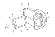
図1は第1の実施形態におけるビデオカメラの構成を示す斜視図である。ビデオカメラは、カメラ本体1の前部にレンズ2、その後部にカラービューファインダ6、その側部に液晶モニタ4等を有する。
[First Embodiment]
FIG. 1 is a perspective view showing the configuration of the video camera according to the first embodiment. The video camera has a
液晶モニタ4は、再生映像や撮影映像を表示可能な液晶パネル5、およびこの液晶パネル5の後部に設けられた液晶バックライト3を有するバックライト方式の液晶表示装置である。液晶モニタ4は、ヒンジ部7によりカメラ本体1に取り付けられており、図中矢印A方向に開閉自在であるとともに、図中矢印B方向に回動自在である。すなわち、液晶モニタ4(液晶パネル5)は、カメラ本体1に対し、ヒンジ部7に設けられた開閉軸を中心に開閉自在、かつこの開閉軸に対して直交するヒンジ部7に設けられた回動軸を中心に回動自在である。従って、液晶パネル5は被写体側あるいは撮影者側に反転自在である。なお、液晶モニタ4(液晶パネル5)は表示手段に相当する。また、ヒンジ部7の内部には、液晶モニタ4の開閉および反転を検出するスイッチが設けられている。
The
液晶モニタ4には、十字操作キー8が設けられている。十字操作キー8は、上下左右に操作自在であり、ビデオカメラの設定を表示画面上で行うためのメニュー操作時に使用される。操作キー9は、ビデオカメラの設定をON/OFFに操作するための切替スイッチである。
The
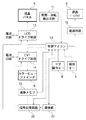
図2は主に液晶モニタ4の制御に係る部分の制御回路の構成を示す図である。この制御回路はカメラ本体1の内部に設けられる。また、この制御回路は、液晶パネル5を駆動するLCDドライブ回路13、カラービューファインダ6を駆動するCVFドライブ回路14、およびビデオカメラを制御する制御マイコン10を有する。また、制御回路は、ヒンジ部7内部に設けられたスイッチにより液晶モニタ4の開閉・反転状態を検出する開閉・反転検出回路11、および電源回路12を有する。また、制御マイコン10には、前述したメニュー画面操作を行う十字操作キー8、および設定をON/OFFに切り替える操作キー9が接続される。ここで、開閉・反転検出回路11は、請求項に記載の表示手段が向いている状態を検出する状態検出手段、開閉状態を検出する開閉検出手段、および回動状態を検出する回動検出手段に対応している。
FIG. 2 is a diagram showing a configuration of a control circuit of a part mainly related to the control of the
電源回路12は液晶バックライト3に電源供給を行う。また、制御回路は、撮影した画像データに対し必要な信号処理を行う信号処理回路22、および信号処理された画像データを記憶する画像メモリ23を有する。信号処理回路22には、撮像素子、CDS回路、A/D変換器等(図示せず)を有し、撮影した画像データを出力する撮像部21が接続される。
The
制御マイコン10は、開閉・反転検出回路11から入力された情報により、LCDドライブ回路13およびCVFドライブ回路14を制御し、液晶パネル5およびカラービューファインダ6の点灯/消灯および表示画像を切り替える。また、制御マイコン10は、十字操作キー8や操作キー9により入力された情報に従って、LCDドライブ回路13を制御し、液晶パネル5の表示を全白表示あるいは映像表示に切り替える。
The
電源回路12は、制御マイコン10によって制御され、液晶バックライト3に供給する電流を変更し、液晶バックライト3の輝度を調節する。
The
上記構成を有する撮像装置の動作について説明する。ビデオカメラは、レンズ2を介して入射する被写体の光信号を、撮像部21内の図示しない撮像素子(CCD)により電気信号に変換して映像信号を得る。この映像信号は、信号処理回路22で各種信号処理が行われると、液晶パネル5およびカラービューファインダ6に表示される。一方、撮影者が録画ボタンを押すことで、カメラ本体1の内部に装填された記録媒体に映像信号および音声信号が記録される。
The operation of the imaging apparatus having the above configuration will be described. The video camera obtains a video signal by converting an optical signal of a subject incident through the
また、前述したように、カメラ本体1には、撮影中の映像や再生した映像を表示するための液晶パネル5およびカラービューファインダ6が設けられている。液晶モニタ4は、ヒンジ部7により、図1の矢印A方向に開閉自在かつ矢印B方向に回動自在である。
Further, as described above, the
液晶パネル5が撮影者側を向いた正転状態では、液晶パネル5が点灯し、カラービューファインダ6は消灯している。従って、撮影者は液晶パネル5の映像を見ながら撮影する。
In the forward rotation state where the
一方、液晶パネル5がカメラ本体1側に向いて収納されている収納状態では、液晶パネル5が消灯し、カラービューファインダ6は点灯している。従って、撮影者はカラービューファインダ6を覗きながら撮影する。
On the other hand, in the storage state in which the
また、液晶パネル5が被写体側、つまりレンズ2と同方向に向いた対面状態では、液晶パネル5およびカラービューファインダ6は共に点灯している。液晶パネル5をビデオライトとして使用していない状態では、正転状態でも対面状態でも、液晶パネル5には映像信号に基づく映像が表示されている。
When the
また、液晶パネル5の液晶バックライト3の輝度には、通常輝度モードと、通常の輝度よりも輝度を上げた高輝度モードとの2種類が設定可能である。高輝度モードは、主に屋外等での視認性向上のために使用される。ユーザは、メニュー操作により通常輝度モードと高輝度モードのいずれかを選択して設定することができる。
In addition, the brightness of the
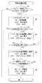
図3は液晶パネル5をビデオライトとして使用するビデオライトモード時の動作手順を示すフローチャートである。この動作プログラムは制御マイコン10内のROM(図示せず)に格納されており、制御マイコン10内のCPUによって実行される。
FIG. 3 is a flowchart showing an operation procedure in the video light mode in which the
まず、撮影者は、カメラ本体1の電源を投入し、液晶パネル5を撮影者側に向けた正転状態の撮影モードで撮影を行うものとする。この撮影モードの場合、レンズ2から入射して光電変換された映像信号に基づく映像は、液晶パネル5に表示される。この状態では、液晶バックライト3の輝度は、ユーザによって設定された輝度モード(ユーザ設定の輝度モード)になっている。
First, it is assumed that the photographer turns on the power of the
この表示状態において、制御マイコン10は、撮影者によって十字操作キー8がメニュー画面上で操作され、ビデオライトモードが設定されたか否かを判別する(ステップS1)。図4はビデオライトモード設定画面の一例を示す図である。メニュー画面の画像は、OSD表示(オンスクリーンディスプレイ表示)によって映像に重畳され、表示される。そして、ビデオライトモード設定画面はメニュー画面から展開される。ビデオライトモードに設定する際、撮影者は、ビデオライトモード設定画面において、十字操作キー8を右に操作してカーソル81を移動させ、「ON」を選択する。ここで、ビデオライトモードが設定されない場合、制御マイコン10はそのまま本処理を終了する。
In this display state, the
一方、ビデオライトモードが設定された場合、制御マイコン10は、十字操作キー8からのビデオライトモードON信号により、LCDドライブ回路13を制御し、液晶パネル5を全白表示に切り替える(ステップS2)。また、このとき、制御マイコン10は、電源回路12を制御し、液晶バックライト3の輝度をユーザ設定に関係なく強制的に標準輝度モードに設定する。ここで、電源回路12は請求項に記載の輝度調節手段に相当する。さらに、このとき、制御マイコン10は、CVFドライブ回路14を制御し、カラービューファインダ6を強制的に点灯させる。このように、制御マイコン10は、ビデオライトモード時、開閉・反転検出回路11の検出結果に関係なく、カラービューファインダ6を強制的に点灯させる。点灯したカラービューファインダ6には、図4のビデオライトモード設定画面が表示される。
On the other hand, when the video light mode is set, the
ユーザは、液晶モニタ4を矢印B(図1参照)のように回転させ、被写体側に、つまりレンズ2と同方向に向けることにより、液晶パネル5を、被写体を照らすためのビデオライトとして使用することができる。制御マイコン10は、開閉・反転検出回路11からの反転情報により液晶パネル5が被写体側に向いている反転状態になったか否かを判別する(ステップS3)。反転状態になっていない場合、制御マイコン10は、ステップS6の処理に進む。一方、反転状態になっている場合、制御マイコン10は、開閉・反転検出回路11からの反転情報に従って、電源回路12を制御し、液晶バックライト3の輝度を高輝度モードに設定する(ステップS4)。ここで、制御マイコン10によって行われるステップS4の処理は、請求項に記載の輝度制御手段に相当する。また、このとき、制御マイコン10は、カラービューファインダ6のメニュー画面表示(ビデオライトモード設定画面表示)を消去する。このように、メニュー画面表示を消去することにより、カラービューファインダ6に表示された映像を見易くすることができる。
The user uses the
そして、制御マイコン10は、開閉・反転検出回路11からの正転情報により、液晶パネル5が正転状態に戻ったか否かを判別する(ステップS5)。反転状態のままである場合、制御マイコン10はステップS5の処理を繰り返す。一方、撮影者が液晶パネル5を回転させて正転状態に戻すと、制御マイコン10は、電源回路12を制御し、液晶バックライト3の輝度を標準輝度モードに戻す(ステップS6)。また、このとき、制御マイコン10は、カラービューファインダ6にビデオライトモード設定画面(図4参照)を表示させる。また、ステップS3で反転状態になっていない場合も、ステップS6で液晶バックライト3の標準輝度モードにおける輝度、およびビデオライトモード設定画面の表示が継続される。
Then, the
そして、制御マイコン10は、十字操作キー8の操作によりビデオライトモードの設定が解除されたか否かを判別する(ステップS7)。ここで、ビデオライトモードを解除する場合、撮影者はビデオライトモード設定画面上で十字操作キー8を左に操作してカーソル81を移動させ、「OFF」を選択する。ビデオライトモードの設定が解除されない場合、つまり「ON」が選択された状態のままの場合、制御マイコン10は、ステップS2に戻り、同様の処理を行う。一方、ビデオライトモードの設定が解除された場合、つまり撮影者が十字操作キー8を左に操作して「OFF」を選択した場合、制御マイコン10は、ビデオライトモードの解除動作を行う(ステップS8)。すなわち、制御マイコン10は、十字操作キー8からのビデオライトモードOFF信号により、LCDドライブ回路13を制御し、液晶パネル5の全白表示を終了させて映像信号を表示させる。また、このとき、制御マイコン10は、電源回路12を制御し、液晶バックライト3の輝度をユーザ設定の輝度モードに戻す。さらに、このとき、制御マイコン10は、CVFドライブ回路14を制御し、カラービューファインダ6を消灯させる。これにより、ビデオカメラは、通常撮影時の通常状態に復帰する。この後、制御マイコン10は本処理を終了する。
Then, the
このように、第1の実施形態の撮像装置によれば、ビデオライトモード時、液晶パネルが撮影者側に向いている場合にその消費電力の削減を図ることができる。また、液晶パネルが撮影者側を向いている状態では、液晶バックライトの輝度を低下させることにより、ビデオライトモードに切り替えた際、ユーザが眩しく感じるおそれを無くすことができる。 As described above, according to the imaging apparatus of the first embodiment, in the video light mode, when the liquid crystal panel is facing the photographer, the power consumption can be reduced. Further, when the liquid crystal panel is facing the photographer, the brightness of the liquid crystal backlight is reduced, so that the user can be prevented from feeling dazzled when switching to the video light mode.
なお、本実施形態では、ビデオライトモード時、液晶パネルが撮影者側に向いている場合、液晶バックライトの輝度を標準輝度モードに設定したが、高輝度モード時の輝度よりも低い任意の輝度に設定してもよく、同様の効果が得られる。 In this embodiment, in the video light mode, when the liquid crystal panel is facing the photographer, the luminance of the liquid crystal backlight is set to the standard luminance mode, but any luminance lower than the luminance in the high luminance mode is set. The same effect can be obtained.
[第2の実施形態]
第2の実施形態のビデオカメラの外観および構成は、前記第1の実施形態と同一であるので、同一の構成要素については、同一の符号を用いることによりその説明を省略する。
[Second Embodiment]
Since the appearance and configuration of the video camera of the second embodiment are the same as those of the first embodiment, the description of the same components is omitted by using the same reference numerals.
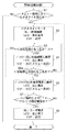
図5は第2の実施形態におけるビデオライトモード時の動作手順を示すフローチャートである。この動作プログラムは制御マイコン10内のROM(図示せず)に格納されており、制御マイコン10内のCPUによって実行される。なお、前記第1の実施形態と同一のステップ処理については同一のステップ番号を付すこととする。
FIG. 5 is a flowchart showing an operation procedure in the video light mode in the second embodiment. This operation program is stored in a ROM (not shown) in the
まず、撮影者は、カメラ本体1の電源を投入し、液晶パネル5を撮影者側に向けた正転状態の撮影モードで撮影を行うものとする。この撮影モードの場合、レンズ2から入射して光電変換された映像信号は、液晶パネル5に表示される。ここで、液晶バックライト3の輝度は、ユーザによって設定された輝度モード(ユーザ設定の輝度モード)になっている。
First, it is assumed that the photographer turns on the power of the
この表示状態において、制御マイコン10は、撮影者によって十字操作キー8がメニュー画面上で操作され、ビデオライトモードが設定されたか否かを判別する(ステップS1)。メニュー画面(図4参照)の画像は、OSD表示(オンスクリーンディスプレイ表示)によって映像に重畳され、表示される。そして、ビデオライトモード設定画面はメニュー画面から展開される。ビデオライトモードに設定する際、撮影者は、ビデオライトモード設定画面において、十字操作キー8を右に操作してカーソル81を移動させ、「ON」を選択する。ここで、ビデオライトモードが設定されない場合、制御マイコン10はそのまま本処理を終了する。
In this display state, the
一方、ビデオライトモードが設定された場合、制御マイコン10は、十字操作キー8からのビデオライトモードON信号により、LCDドライブ回路13を制御し、液晶パネル5を全白表示に切り替える(ステップS2)。また、制御マイコン10は、電源回路12を制御し、液晶バックライト3の輝度をユーザ設定に関係なく強制的に標準輝度モードに設定する。さらに、このとき、制御マイコン10は、CVFドライブ回路14を制御し、カラービューファインダ6を強制的に点灯させる。このように、制御マイコン10は、ビデオライトモード時、開閉・反転検出回路11の検出結果に関係なく、カラービューファインダ6を強制的に点灯させる。点灯したカラービューファインダ6には、図4のビデオライトモード設定画面が表示される。
On the other hand, when the video light mode is set, the
ユーザは、液晶モニタ4を矢印B(図1参照)のように回転させ、被写体側に、つまりレンズ2と同方向に向けることにより、液晶パネル5を、被写体を照らすためのビデオライトとして使用することができる。制御マイコン10は、開閉・反転検出回路11からの反転情報により液晶パネル5が被写体側に向いている反転状態になったか否かを判別する(ステップS3)。反転状態になっていない場合、制御マイコン10は、ステップS6の処理に進む。一方、反転状態になっている場合、制御マイコン10は、開閉・反転検出回路11からの反転情報に従って、電源回路12を制御し、液晶バックライト3の輝度を高輝度モードに設定する(ステップS4)。また、このとき、制御マイコン10は、カラービューファインダ6のメニュー画面表示(ビデオライトモード設定画面表示)を消去する。このように、メニュー画面表示を消去することにより、カラービューファインダ6に表示された映像を見易くすることができる。
The user uses the
ここで、ユーザは、反転状態にある液晶モニタ4を矢印A(図1参照)のようにカメラ本体1に閉じて反転閉止状態にすることが可能である。そして、制御マイコン10は、開閉・反転検出回路11からの反転かつ閉止情報により、液晶パネル5が反転閉止状態になったか否かを判別する(ステップS5A)。
Here, the user can close the liquid crystal monitor 4 in the inverted state to the inverted camera closed state by closing the
反転閉止状態になっていない場合、制御マイコン10はステップS3の処理に戻る。一方、撮影者が液晶パネル5を閉じて反転閉止状態にすると、制御マイコン10は、電源回路12を制御し、液晶バックライト3の輝度を標準輝度モードに戻す(ステップS6)。また、このとき、制御マイコン10は、カラービューファインダ6にビデオライトモード設定画面(図4参照)を表示させる。また、ステップS3で反転状態になっていない場合も、ステップS6で液晶バックライト3の標準輝度モードによる輝度、およびビデオライトモード設定画面の表示が継続される。
If it is not in the reverse closed state, the
そして、制御マイコン10は、十字操作キー8の操作によりビデオライトモードの設定が解除されたか否かを判別する(ステップS7)。ここで、ビデオライトモードを解除する場合、撮影者はビデオライトモード設定画面上で十字操作キー8を左に操作してカーソル81を移動させ、「OFF」を選択する。ビデオライトモードの設定が解除されない場合、つまり「ON」が選択された状態のままの場合、制御マイコン10は、ステップS2に戻り、同様の処理を行う。一方、ビデオライトモードの設定が解除された場合、つまり撮影者が十字操作キー8を左に操作して「OFF」を選択した場合、制御マイコン10は、ビデオライトモードの解除動作を行う(ステップS8)。すなわち、制御マイコン10は、十字操作キー8からのビデオライトモードOFF信号により、LCDドライブ回路13を制御し、液晶パネル5の全白表示を終了させて映像信号を表示させる。また、このとき、制御マイコン10は、電源回路12を制御し、液晶バックライト3の輝度をユーザ設定の輝度モードに戻す。さらに、このとき、制御マイコン10は、CVFドライブ回路14を制御し、カラービューファインダ6を消灯させる。これにより、ビデオカメラは、通常撮影時の通常状態に復帰する。この後、制御マイコン10は本処理を終了する。
Then, the
このように、第2の実施形態の撮像装置によれば、ビデオライトモード時、液晶パネルが反転閉止状態にある場合、その消費電力の削減を図ることができる。なお、本実施形態では、ビデオライトモード時、液晶パネルが反転閉止状態にある場合、液晶バックライトの輝度を標準輝度モードに設定したが、高輝度モード時の輝度よりも低い任意の輝度に設定してもよく、同様の効果が得られる。 Thus, according to the imaging device of the second embodiment, when the liquid crystal panel is in the inverted closed state in the video light mode, the power consumption can be reduced. In this embodiment, when the liquid crystal panel is in the inverted closed state in the video light mode, the luminance of the liquid crystal backlight is set to the standard luminance mode, but is set to an arbitrary luminance lower than the luminance in the high luminance mode. The same effect can be obtained.
なお、本発明は、上記実施形態の構成に限られるものではなく、特許請求の範囲で示した機能、または本実施形態の構成が持つ機能が達成できる構成であればどのようなものであっても適用可能である。 The present invention is not limited to the configuration of the above-described embodiment, and any configuration can be used as long as the functions shown in the claims or the functions of the configuration of the present embodiment can be achieved. Is also applicable.
例えば、上記実施形態では、液晶パネルが正転状態に戻った場合、あるいは反転閉止状態になった場合、液晶バックライトの輝度を標準輝度モードに設定したが、これらの状態に限られなくてもよい。すなわち、液晶パネルが被写体側に向いていない、反転状態以外の任意の状態にある場合、液晶バックライトの輝度を標準輝度モードに設定するようにしてもよい。 For example, in the above embodiment, when the liquid crystal panel returns to the normal rotation state or when the liquid crystal panel is in the reverse closed state, the luminance of the liquid crystal backlight is set to the standard luminance mode. However, the present invention is not limited to these states. Good. That is, when the liquid crystal panel is not facing the subject side and is in any state other than the inverted state, the luminance of the liquid crystal backlight may be set to the standard luminance mode.
また、上記各実施形態では、表示装置として、バックライト方式のLCDパネルを用いているが、有機ELディスプレイなどの自発光型の表示装置を用いてもよい。その他、表面電界ディスプレイ(SED)、プラズマディスプレイなどを用いてもよい。 In each of the above embodiments, a backlight type LCD panel is used as the display device, but a self-luminous display device such as an organic EL display may be used. In addition, a surface electric field display (SED), a plasma display, or the like may be used.
また、上記実施形態の撮像装置では、液晶パネルがカメラ本体の側面に対し、開閉かつ回動自在に設けられていたが、このような構造に限られるものではないことは勿論である。例えば、カメラ本体の前面と背面とに液晶パネルが着脱自在に取り付けられる構造の撮像装置であってもよい。この場合、液晶パネルをカメラ本体の前面に取り付けることで、ビデオライトとして使用可能である。 In the imaging apparatus of the above embodiment, the liquid crystal panel is provided so as to be openable and closable and rotatable with respect to the side surface of the camera body. However, the present invention is not limited to such a structure. For example, an imaging apparatus having a structure in which a liquid crystal panel is detachably attached to the front and back of the camera body may be used. In this case, the liquid crystal panel can be used as a video light by attaching it to the front surface of the camera body.
また、上記実施形態では、撮像装置としてビデオカメラに適用された場合を示したが、デジタルスチルカメラに適用されてもよいことは勿論である。 Moreover, although the case where it applied to the video camera as an imaging device was shown in the said embodiment, of course, you may apply to a digital still camera.
1 カメラ本体
3 液晶バックライト
4 液晶モニタ
5 液晶パネル
6 カラービューファインダ(CVF)
8 十字操作キー
9 操作キー
10 制御マイコン
11 開閉・反転検出回路
DESCRIPTION OF
8
Claims (5)
前記被写体側に反転自在に設けられ、前記撮像された被写体の映像表示あるいは全白表示を行う表示手段と、
前記表示手段が前記被写体側に向いている反転状態を検出する状態検出手段と、
前記表示手段をビデオライトとして使用するためのビデオライトモードを選択する選択手段と、
前記ビデオライトモードが選択された場合、前記表示手段を全白表示に切り替える表示制御手段と、
前記表示手段の輝度を調節する輝度調節手段と、
前記表示手段が前記被写体側に向いていない、前記反転状態以外の状態が検出された場合、前記輝度調節手段を制御し、前記全白表示が行われている前記表示手段の輝度を、前記反転状態の場合と比べ、低下させる輝度制御手段とを備えたことを特徴とする撮像装置。 An imaging device for imaging a subject,
Display means provided on the subject side so as to be reversible, and performing video display or all white display of the imaged subject;
State detecting means for detecting a reverse state in which the display means faces the subject side;
Selecting means for selecting a video light mode for using the display means as a video light;
Display control means for switching the display means to all white display when the video light mode is selected;
Brightness adjusting means for adjusting the brightness of the display means;
When a state other than the inverted state is detected in which the display unit is not directed to the subject side, the luminance adjusting unit is controlled to change the luminance of the display unit in which the all white display is performed. An imaging apparatus comprising a luminance control means for reducing the brightness as compared with the state.
前記被写体側あるいは撮影者側に反転自在に設けられ、前記撮像された被写体の映像表示あるいは全白表示を行う表示手段と、
前記表示手段が前記撮影者側に向いている正転状態あるいは前記被写体側に向いている反転状態を検出する状態検出手段と、
前記表示手段をビデオライトとして使用するためのビデオライトモードを選択する選択手段と、
前記ビデオライトモードが選択された場合、前記表示手段を全白表示に切り替える表示制御手段と、
前記表示手段の輝度を調節する輝度調節手段と、
前記表示手段が前記撮影者側に向いている正転状態が検出された場合、前記輝度調節手段を制御し、前記全白表示が行われている前記表示手段の輝度を、前記反転状態の場合と比べ、低下させる輝度制御手段とを備えたことを特徴とする撮像装置。 An imaging device for imaging a subject,
Display means provided on the subject side or photographer side so as to be reversible, and performing video display or all-white display of the captured subject;
State detecting means for detecting a normal rotation state in which the display unit is directed toward the photographer side or a reverse state in which the display unit is directed toward the subject side; and
Selecting means for selecting a video light mode for using the display means as a video light;
Display control means for switching the display means to all white display when the video light mode is selected;
Brightness adjusting means for adjusting the brightness of the display means;
When a normal rotation state in which the display unit is facing the photographer is detected, the luminance adjustment unit is controlled, and the luminance of the display unit in which the all white display is performed is set to the reverse state. An image pickup apparatus comprising a luminance control means for reducing the brightness as compared with the above.
前記撮像装置の本体に対し、開閉軸を中心に開閉自在、かつ前記開閉軸に対して直交する回動軸を中心に回動自在に設けられ、前記撮像された被写体の映像表示あるいは全白表示を行う表示手段と、
前記表示手段が前記被写体側に向いている反転状態から、前記開閉軸を中心に前記撮像装置の本体に閉じられた反転閉止状態を検出する状態検出手段と、
前記表示手段をビデオライトとして使用するためのビデオライトモードを選択する選択手段と、
前記ビデオライトモードが選択された場合、前記表示手段を全白表示に切り替える表示制御手段と、
前記表示手段の輝度を調節する輝度調節手段と、
前記表示手段が前記撮像装置の本体に閉じられた反転閉止状態が検出された場合、前記輝度調節手段を制御し、前記全白表示が行われている前記表示手段の輝度を、前記反転状態の場合と比べ、低下させる輝度制御手段とを備えたことを特徴とする撮像装置。 An imaging device for imaging a subject,
The main body of the image pickup apparatus is provided so as to be openable and closable around an opening / closing axis and to be rotatable around a rotation axis orthogonal to the opening / closing axis, and to display an image of the imaged subject or an all-white display Display means for performing
A state detecting means for detecting a reverse closed state closed by the main body of the imaging device around the open / close axis from the reverse state in which the display means faces the subject;
Selecting means for selecting a video light mode for using the display means as a video light;
Display control means for switching the display means to all white display when the video light mode is selected;
Brightness adjusting means for adjusting the brightness of the display means;
When a reverse closed state in which the display unit is closed to the main body of the imaging device is detected, the luminance adjusting unit is controlled to change the luminance of the display unit in which the all white display is performed in the reverse state. An image pickup apparatus comprising a luminance control means for reducing the brightness as compared with the case.
前記輝度調節手段は、前記バックライトの輝度を調節することを特徴とする請求項1乃至4のいずれかに記載の撮像装置。 The display means is a liquid crystal panel having a backlight,
The imaging apparatus according to claim 1, wherein the brightness adjusting unit adjusts the brightness of the backlight.
Priority Applications (4)
| Application Number | Priority Date | Filing Date | Title |
|---|---|---|---|
| JP2007286474A JP4999643B2 (en) | 2007-11-02 | 2007-11-02 | Imaging device |
| CN2010105661892A CN101982968A (en) | 2007-11-02 | 2008-10-31 | Image pickup apparatus |
| US12/263,449 US20090115880A1 (en) | 2007-11-02 | 2008-10-31 | Image pickup apparatus and display controlling method therefor |
| CN2010105661869A CN101982967B (en) | 2007-11-02 | 2008-10-31 | Image pickup apparatus |
Applications Claiming Priority (1)
| Application Number | Priority Date | Filing Date | Title |
|---|---|---|---|
| JP2007286474A JP4999643B2 (en) | 2007-11-02 | 2007-11-02 | Imaging device |
Publications (3)
| Publication Number | Publication Date |
|---|---|
| JP2009117994A JP2009117994A (en) | 2009-05-28 |
| JP2009117994A5 JP2009117994A5 (en) | 2010-12-16 |
| JP4999643B2 true JP4999643B2 (en) | 2012-08-15 |
Family
ID=40784658
Family Applications (1)
| Application Number | Title | Priority Date | Filing Date |
|---|---|---|---|
| JP2007286474A Expired - Fee Related JP4999643B2 (en) | 2007-11-02 | 2007-11-02 | Imaging device |
Country Status (1)
| Country | Link |
|---|---|
| JP (1) | JP4999643B2 (en) |
Families Citing this family (2)
| Publication number | Priority date | Publication date | Assignee | Title |
|---|---|---|---|---|
| JP5327211B2 (en) * | 2010-12-28 | 2013-10-30 | カシオ計算機株式会社 | Imaging apparatus, imaging control method, and program |
| JP5754213B2 (en) * | 2011-03-31 | 2015-07-29 | 株式会社ニコン | Hinge unit and electronic device |
Family Cites Families (5)
| Publication number | Priority date | Publication date | Assignee | Title |
|---|---|---|---|---|
| JPH11355620A (en) * | 1998-06-08 | 1999-12-24 | Sony Corp | Image pickup device |
| JP4126153B2 (en) * | 2000-12-01 | 2008-07-30 | 株式会社リコー | camera |
| JP4269705B2 (en) * | 2003-01-31 | 2009-05-27 | パナソニック株式会社 | Imaging device |
| JP2005079702A (en) * | 2003-08-28 | 2005-03-24 | Sony Corp | Imaging apparatus |
| JP2005184186A (en) * | 2003-12-17 | 2005-07-07 | Matsushita Electric Ind Co Ltd | Imaging apparatus |
-
2007
- 2007-11-02 JP JP2007286474A patent/JP4999643B2/en not_active Expired - Fee Related
Also Published As
| Publication number | Publication date |
|---|---|
| JP2009117994A (en) | 2009-05-28 |
Similar Documents
| Publication | Publication Date | Title |
|---|---|---|
| JP5251463B2 (en) | Imaging device | |
| JP5228858B2 (en) | Imaging device | |
| US8411049B2 (en) | Information processing apparatus | |
| US10136068B2 (en) | Imaging apparatus | |
| US20090115880A1 (en) | Image pickup apparatus and display controlling method therefor | |
| JP2010160272A (en) | Display control device and control method thereof | |
| WO2017159545A1 (en) | Camera | |
| JP2007316599A (en) | Display control device and display control program | |
| US20210289143A1 (en) | Apparatus, capturing apparatus, control method and storage medium | |
| JP4999643B2 (en) | Imaging device | |
| JP2009130825A (en) | Photographing apparatus | |
| JP4269705B2 (en) | Imaging device | |
| JP2009117993A (en) | Imaging apparatus and display control method thereof | |
| JP4457791B2 (en) | Display device | |
| JPH11355784A (en) | Electronic camera | |
| JP2009124564A (en) | Imaging apparatus and display control method thereof | |
| JP5377168B2 (en) | Imaging device | |
| US9723207B2 (en) | Imaging device and control method therefor | |
| JP2009128789A (en) | Image display device | |
| JP2007110220A (en) | Imaging apparatus | |
| JP4647538B2 (en) | Imaging apparatus and display method | |
| JPH11352389A (en) | Electronic finder camera | |
| JP2008258876A (en) | Camera and display device luminance control method of camera | |
| JPH09200595A (en) | Video camera with liquid crystal display device | |
| JP2017130879A (en) | Imaging apparatus and control method for imaging apparatus |
Legal Events
| Date | Code | Title | Description |
|---|---|---|---|
| A521 | Request for written amendment filed |
Free format text: JAPANESE INTERMEDIATE CODE: A523 Effective date: 20101101 |
|
| A621 | Written request for application examination |
Free format text: JAPANESE INTERMEDIATE CODE: A621 Effective date: 20101101 |
|
| A977 | Report on retrieval |
Free format text: JAPANESE INTERMEDIATE CODE: A971007 Effective date: 20120313 |
|
| TRDD | Decision of grant or rejection written | ||
| A01 | Written decision to grant a patent or to grant a registration (utility model) |
Free format text: JAPANESE INTERMEDIATE CODE: A01 Effective date: 20120417 |
|
| A01 | Written decision to grant a patent or to grant a registration (utility model) |
Free format text: JAPANESE INTERMEDIATE CODE: A01 |
|
| A61 | First payment of annual fees (during grant procedure) |
Free format text: JAPANESE INTERMEDIATE CODE: A61 Effective date: 20120515 |
|
| R151 | Written notification of patent or utility model registration |
Ref document number: 4999643 Country of ref document: JP Free format text: JAPANESE INTERMEDIATE CODE: R151 |
|
| FPAY | Renewal fee payment (event date is renewal date of database) |
Free format text: PAYMENT UNTIL: 20150525 Year of fee payment: 3 |
|
| LAPS | Cancellation because of no payment of annual fees |