JP4999019B2 - Caulking forgetting prevention system and method for piping joints - Google Patents
Caulking forgetting prevention system and method for piping joints Download PDFInfo
- Publication number
- JP4999019B2 JP4999019B2 JP2010074533A JP2010074533A JP4999019B2 JP 4999019 B2 JP4999019 B2 JP 4999019B2 JP 2010074533 A JP2010074533 A JP 2010074533A JP 2010074533 A JP2010074533 A JP 2010074533A JP 4999019 B2 JP4999019 B2 JP 4999019B2
- Authority
- JP
- Japan
- Prior art keywords
- caulking
- joint
- tag
- identification information
- pipe
- Prior art date
- Legal status (The legal status is an assumption and is not a legal conclusion. Google has not performed a legal analysis and makes no representation as to the accuracy of the status listed.)
- Active
Links
- 230000002265 prevention Effects 0.000 title claims description 28
- 238000000034 method Methods 0.000 title claims description 23
- 230000008859 change Effects 0.000 claims description 8
- 238000010276 construction Methods 0.000 description 15
- 238000010586 diagram Methods 0.000 description 10
- 238000004891 communication Methods 0.000 description 6
- 238000012790 confirmation Methods 0.000 description 5
- 239000004973 liquid crystal related substance Substances 0.000 description 3
- 230000008878 coupling Effects 0.000 description 2
- 238000010168 coupling process Methods 0.000 description 2
- 238000005859 coupling reaction Methods 0.000 description 2
- 238000002788 crimping Methods 0.000 description 2
- 230000003247 decreasing effect Effects 0.000 description 2
- 238000001514 detection method Methods 0.000 description 2
- 238000011161 development Methods 0.000 description 2
- 238000004519 manufacturing process Methods 0.000 description 2
- 230000008569 process Effects 0.000 description 2
- XLYOFNOQVPJJNP-UHFFFAOYSA-N water Substances O XLYOFNOQVPJJNP-UHFFFAOYSA-N 0.000 description 2
- 230000002776 aggregation Effects 0.000 description 1
- 230000007423 decrease Effects 0.000 description 1
- 230000000694 effects Effects 0.000 description 1
- 238000003780 insertion Methods 0.000 description 1
- 230000037431 insertion Effects 0.000 description 1
- 238000009413 insulation Methods 0.000 description 1
- 230000007246 mechanism Effects 0.000 description 1
- 230000004048 modification Effects 0.000 description 1
- 238000012986 modification Methods 0.000 description 1
- 238000012545 processing Methods 0.000 description 1
- 239000000126 substance Substances 0.000 description 1
Images


Description
本発明は、専用のかしめ工具を使用して配管に継手をかしめて接合する際に該継手のかしめ忘れを防止するための配管継手用かしめ忘れ防止システム及びその方法に関するものである。 The present invention relates to an anti-caulking system for pipe joints and a method thereof for preventing forgetting caulking of the joint when the joint is caulked and joined to the pipe using a dedicated caulking tool.
従来、配管用の継手には、配管に差し込んだ後、専用のかしめ工具を使用して配管にかしめて接合するタイプのものがあり、この種の市販されている継手としては、例えば、積水化学工業株式会社製のメタキュット(例えば、非特許文献1参照)、株式会社ベンカン・ジャパン製のモルコジョイント、ダブルプレス、CUプレス(例えば、非特許文献2参照)、東洋フィッティング株式会社製のプロプレスS(例えば、非特許文献3参照)、シーケー金属株式会社製のSUSプレス(例えば、非特許文献4参照)などが知られている。 Conventionally, there is a type of joint for piping which is inserted into the pipe and then caulked to the pipe using a special caulking tool. As this type of commercially available joint, for example, Sekisui Chemical Metacut manufactured by Kogyo Co., Ltd. (for example, see Non-Patent Document 1), Morco Joint, Double Press, CU Press (for example, refer to Non-Patent Document 2) manufactured by Bencan Japan Co., Ltd., Propress S manufactured by Toyo Fitting Co., Ltd. (For example, refer nonpatent literature 3), SUS press (for example, refer nonpatent literature 4) by KK Metal Co., Ltd., etc. are known.
従来、この種の継手を配管に接合する場合、作業効率を高めるため、継手を配管に差し込む作業をまとめて行った後に、かしめ作業をまとめて行う施工方法が採られる。ところが、この施工方法では、かしめ作業の確認の不備により、かしめ忘れが発生するおそれがあり、そのまま、後工程の保温工事が行われてしまうと、外観からかしめ忘れを発見することができないため、配管内に通水した際にかしめ忘れ箇所から水漏れ事故が発生することがある。 Conventionally, when this type of joint is joined to a pipe, in order to increase work efficiency, a construction method in which the caulking work is collectively performed after the work of inserting the joint into the pipe is collectively performed. However, in this construction method, forgetting caulking may occur due to inadequate confirmation of caulking work, and if heat insulation work in the subsequent process is performed as it is, it is impossible to find forgetting caulking from the appearance, When water is passed through the pipe, a water leakage accident may occur from the place where the caulking is forgotten.
そこで、このような問題を解決すべく、実際の施工現場では、継手のかしめ作業完了後に別の作業員が目視で確認して確認済みのシールなどを継手に貼付するといったかしめ忘れ防止方法が採られている。 Therefore, in order to solve such problems, a method for preventing caulking is used at the actual construction site, in which another worker visually confirms and attaches a confirmed seal to the joint after completion of the joint caulking work. It has been.
しかしながら、上記した従来のかしめ忘れ防止方法では、継手が目視し難い場所にある場合には作業員が見落とす可能性があり、万全の対策とは言い難かった。 However, in the conventional caulking-forgetting prevention method described above, if the joint is in a place where it is difficult to see, the worker may overlook it, and it is difficult to say that it is a perfect countermeasure.
また、確認データの集計が手作業で行われるため、継手のかしめ箇所数が多いと、集計作業が煩雑になるといった問題があった。 In addition, since the check data is summed manually, there is a problem that the summation work becomes complicated if the number of caulking portions of the joint is large.
本発明は、上記した課題を解決すべくなされたものであり、施工の確認作業が容易であり、継手のかしめ忘れを確実に防止することのできる配管継手用かしめ忘れ防止システム及びその方法を提供することを目的とするものである。 The present invention has been made to solve the above-described problems, and provides a caulking forgetting prevention system and method for a pipe joint that can easily prevent forgetting caulking of a joint, and that can easily prevent the caulking of the joint. It is intended to do.
上記した目的を達成するため、本発明は、専用のかしめ工具を使用して配管に継手をかしめて接合する際に該継手のかしめ忘れを防止するための配管継手用かしめ忘れ防止システムであって、前記継手に対応した固有の識別情報が書き込まれた状態で該継手に取り付けられるICタグと、前記かしめ工具本体に取り付けられ、該かしめ工具本体による前記配管への前記継手のかしめ作業完了後に前記ICタグにかしめ作業の履歴情報を自動的に書き込む制御装置が設けられたアタッチメントと、を備えていることを特徴とする。 In order to achieve the above object, the present invention is a pipe joint forgetting prevention system for a pipe joint for preventing the joint from being forgotten when the joint is caulked and joined to the pipe using a dedicated caulking tool. An IC tag attached to the joint in a state where unique identification information corresponding to the joint is written, and attached to the caulking tool main body, and after the caulking work of the joint to the pipe by the caulking tool main body is completed And an attachment provided with a control device that automatically writes caulking history information to the IC tag.
そして、本発明に係る配管継手用かしめ忘れ防止システムにおいて、前記制御装置は、前記ICタグの識別情報を読み取るための手段と、該読み取られた前記ICタグの識別情報を予め格納された識別情報と照合し、両者が合致した場合に前記かしめ工具本体に対する駆動用電源からの電力供給を許可する手段と、を備えているのが好ましい。 In the system for preventing caulking forgetting for pipe joints according to the present invention, the control device includes means for reading the identification information of the IC tag, and identification information in which the identification information of the read IC tag is stored in advance. And a means for permitting the power supply from the driving power source to the caulking tool main body when the two match.
また、本発明に係る配管継手用かしめ忘れ防止システムにおいて、前記制御装置は、前記かしめ工具の駆動用電源の電流値を検出し、該電流値の特徴的変化を検出した時に前記かしめ工具によるかしめ作業が完了したと判断するのが好ましい。 In the piping joint forgetting prevention system according to the present invention, the control device detects a current value of a power source for driving the caulking tool, and caulking by the caulking tool when a characteristic change of the current value is detected. It is preferable to determine that the work has been completed.
さらに、本発明に係る配管継手用かしめ忘れ防止システムは、前記ICタグに書き込まれた履歴情報を該ICタグに書き込まれた識別情報に対応付けて格納し、該書き込まれた識別情報に対応付けて格納された前記履歴情報と、予め格納されたかしめ接合すべき継手の識別情報とを対応させて出力する端末装置を備えているのが好ましい。 Further, the pipe joint forgetting to caulking prevention system according to the present invention stores the history information written in the IC tag in association with the identification information written in the IC tag, and associates the history information with the written identification information. It is preferable to provide a terminal device that outputs the history information stored in association with the identification information of the joint to be caulked and stored in advance.
さらにまた、本発明に係る配管継手用かしめ忘れ防止システムは、前記ICタグに書き込まれた履歴情報を前記ICタグから直接読み取る読取装置を備えているのが好ましい。 Furthermore, it is preferable that the caulking forgetting prevention system for a pipe joint according to the present invention includes a reading device that directly reads history information written in the IC tag from the IC tag.
また、本発明は、専用のかしめ工具を使用して配管に継手をかしめて接合する際に該継手のかしめ忘れを防止するための配管継手用かしめ忘れ防止方法であって、前記継手に対応した固有の識別情報が書き込まれた状態で該継手に取り付けられるICタグの前記識別情報を制御装置が読み取る工程と、該読み取られた前記ICタグの識別情報を予め格納された識別情報と照合し、両者が合致した場合に前記かしめ工具本体に対する駆動用電源からの電力供給を許可する工程と、前記制御装置が前記かしめ工具の駆動用電源の電流値を検出し、該電流値の特徴的変化を検出した時に前記かしめ工具による前記配管への前記継手のかしめ作業が完了したと判断する工程と、前記かしめ工具本体によるかしめ作業が完了したと判断した後に前記制御装置が前記ICタグにかしめ作業の履歴情報を自動的に書き込む工程と、前記ICタグに書き込まれた履歴情報を該ICタグに書き込まれた識別情報に対応付けて端末装置が格納する工程と、前記書き込まれた識別情報に対応付けて格納された前記履歴情報と、予め格納されたかしめ接合すべき継手の識別情報とを対応させて前記端末装置が出力する工程と、を備えていることを特徴とする。 Further, the present invention is a pipe joint forgetting prevention method for a pipe joint for preventing the joint from being forgotten when the joint is caulked and joined to the pipe using a dedicated caulking tool, and corresponds to the joint. A step in which the control device reads the identification information of the IC tag attached to the joint in a state where the unique identification information is written, and compares the read identification information of the IC tag with previously stored identification information; A step of permitting the power supply from the driving power source to the caulking tool body when the two match, and the control device detects a current value of the driving power source of the caulking tool, and a characteristic change of the current value is detected. A step of determining that the caulking operation of the joint to the pipe by the caulking tool is completed when detected, and the control after determining that the caulking operation by the caulking tool body is completed. Automatically writing the history information of the caulking work on the IC tag, and storing the terminal information in association with the identification information written on the IC tag, the history information written on the IC tag; The terminal device outputs the history information stored in association with the written identification information and the identification information of the joint to be caulked and stored in advance in association with each other. Features.
本発明によれば、一連のかしめ作業を行う間に自動的にICタグにかしめ作業の履歴情報が書き込まれるようになっているため、かしめ作業やその確認作業が簡素化されると共に前記履歴情報の書き込み忘れが生じるおそれがない。 According to the present invention, since the history information of the caulking work is automatically written to the IC tag during a series of caulking work, the caulking work and its confirmation work are simplified and the history information is also recorded. There is no risk of forgetting to write.
また、例え、かしめ作業が未施工の継手があったとしても、その継手を容易に発見することができるため、継手のかしめ忘れを確実に防止し、施工の信頼性を高めることができる。 Moreover, even if there is a joint that has not been caulked, for example, the joint can be easily found, so that forgetting caulking of the joint can be reliably prevented, and the reliability of construction can be improved.
さらに、かしめ工具の改造を軽減、抑制することができるため、製造費用や開発費用を抑制することができる。 Further, since the modification of the caulking tool can be reduced and suppressed, the manufacturing cost and the development cost can be suppressed.
さらにまた、継手のタイプやサイズの違いによってかしめ作業時の駆動用電源の電流値の特徴的変化が異なる場合であっても、ソフトウェアの変更で対応することができるため、いろいろなタイプ及びサイズの継手にも簡単に対応することができる等、種々の優れた効果を得ることができる。 Furthermore, even if the characteristic changes in the current value of the drive power supply during caulking work differ depending on the type and size of the joint, it can be handled by changing the software. Various excellent effects can be obtained, such as being able to easily cope with joints.
以下、図面を参照しつつ、本発明の実施の形態について説明する。ここで、図1の(a)〜(e)は本発明の実施の形態に係る配管継手用かしめ忘れ防止システムの構成を示す説明図、図2は本発明の実施の形態に係る配管継手用かしめ忘れ防止システムのかしめ工具の制御装置を示すブロック図である。 Hereinafter, embodiments of the present invention will be described with reference to the drawings. Here, (a) to (e) in FIG. 1 are explanatory diagrams showing the configuration of the caulking forgetting prevention system for pipe joints according to the embodiment of the present invention, and FIG. 2 is for the pipe joint according to the embodiment of the present invention. It is a block diagram which shows the control apparatus of the caulking tool of the caulking forgetting prevention system.
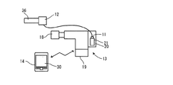
本実施の形態に係る配管継手用かしめ忘れ防止システム10は、ICタグ11が取り付けられた継手12(図1(a))と、継手12専用のかしめ工具13(図1(b))と、施工現場に携帯可能な端末装置としてのPDA(Personal Data Assistant)14(図1(c))と、現場事務所に設置される端末装置としてのホストパソコン15(図1(d))と、施工現場に携帯可能な読取装置としてのスキャニング装置16(図1(e))とを備えて構成されている。
The pipe joint
ICタグ11は、例えばUHF(Ultra High Fequency)帯で使用されるタイプのものであり、予め固有の識別情報として、例えば、識別番号などが書き込まれている。また、継手12としては、例えば、積水化学工業株式会社製のメタキュット、株式会社ベンカン・ジャパン製のモルコジョイント、ダブルプレス、CUプレス、東洋フィッティング株式会社製のプロプレスS、シーケー金属株式会社製のSUSプレスなどが使用される。
The
かしめ工具13は、かしめ工具本体17と、かしめ工具本体17の先端に設けられるかしめ機構部18と、かしめ工具本体17の基端側に設けられる駆動用電源としてのバッテリー(DC12V)19と、バッテリー19とかしめ工具本体17との間の電源回路に割り込ませて装着されるアタッチメント20とにより構成されている。
The
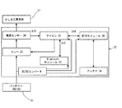
アタッチメント20は、ICタグ11へのデータの読み書き、PDA14との無線通信、及びかしめ工具本体17への電源供給制御を主な機能とする制御装置22と、ICタグ11が挿脱可能なタグホルダー21とを備えている。制御装置22には、図2に示されているように、リレー23、電流センサー24、マイコン25、DC/DCコンバータ26、Bluetooth(登録商標)モジュール27、RFIDモジュール28、及びアンテナ29がそれぞれ内蔵されている。また、タグホルダー21は、アンテナ(図示省略)を内蔵し、ICタグ11への書き込みエラーを防止するため、アンテナ29に近接した位置に設けられているのが好ましい。
The
PDA14は、タッチパネル入力装置を兼ねた液晶表示画面30を備えており、Bluetooth(登録商標)通信を介して、アタッチメント20の制御装置22及びホストパソコン15とのデータ連携機能を有している。そして、予め登録されている作業者の名前とパスワードが入力されることによりログオンされ、本システムの状態及びアタッチメント20との通信履歴が表示されるようになっている。また、予め格納された施工現場の階数と部屋名のリストから特定の階数及び部屋名が選択されることにより、継手12の施工場所が入力されると共に、作業日時等の作業履歴が表示されるようになっている。
The
ホストパソコン15は、CPU(Central Processing Unit)やハードディスクを有する本体31と、液晶ディスプレイ32と、キーボード33とにより構成されており、本体31のハードディスクに集計用ソフトウェアがインストールされる。
The host
スキャニング装置16は、高出力型のRFID(Radio Frequency IDentification)リーダー34と、アンテナ35とにより構成されている。
The
次に、主に図3〜図7を参照しつつ、本発明の実施の形態に係る配管継手用かしめ忘れ防止方法について説明する。ここで、図3は本発明の実施の形態に係る配管継手用かしめ忘れ防止方法を示すフローチャート、図4は本発明の実施の形態に係る配管継手用かしめ忘れ防止方法においてかしめ工具で継手をかしめる前の状態を示す概念図、図5は本発明の実施の形態に係る配管継手用かしめ忘れ防止方法においてかしめ工具で継手をかしめている状態を示す概念図、図6は本発明の実施の形態に係る配管継手用かしめ忘れ防止方法においてかしめ工具で継手をかしめている間の電流検出結果を示す図、図7は本発明の実施の形態に係る配管継手用かしめ忘れ防止方法においてかしめ作業の確認作業を行っている状態を示す概念図である。 Next, a method for preventing caulking forgetting for a pipe joint according to an embodiment of the present invention will be described mainly with reference to FIGS. Here, FIG. 3 is a flow chart showing the method for preventing caulking forgetting a pipe joint according to the embodiment of the present invention, and FIG. 4 shows the method for caulking forgetting caulking for the pipe joint according to the embodiment of the present invention. FIG. 5 is a conceptual diagram showing a state before crimping, FIG. 5 is a conceptual diagram showing a state in which a joint is caulked with a caulking tool in the method for preventing caulking for piping joints according to the embodiment of the present invention, and FIG. 6 is an embodiment of the present invention. FIG. 7 is a diagram showing a current detection result while caulking the joint with a caulking tool in the pipe joint forgetting caulking prevention method according to the embodiment, and FIG. It is a conceptual diagram which shows the state which is performing confirmation work.
先ず、図4に示すように、施工現場に納入された継手12を配管36に差し込み、継手12のICタグ11を、かしめ工具13のアタッチメント20のタグホルダー21に挿入すると、タグホルダー21に設置されたリミットスイッチ(図示省略)によりICタグ11の挿入動作が検出され、これが以下の一連の作業を開始させるトリガーとなる。
First, as shown in FIG. 4, when the joint 12 delivered to the construction site is inserted into the
アタッチメント20では、図3のステップ1(S1)に示されているように、RFIDモジュール28及びアンテナ29を介してICタグ11の識別番号がマイコン25によって読み取られ、その情報はBluetooth(登録商標)通信によってPDA14に送信される。
In the
PDA14では、ステップ2(S2)に示されているように、前記アタッチメント20で読み取られた前記ICタグの識別情報が、予めPDA内のデータベースに格納されたICタグ11の識別番号と照合され、ステップ3(S3)に示されているように、両方の識別番号が合致したかどうかが判断される。
In the
その結果、両方の識別番号が合致したと判断された場合には、ステップ4(S3)に示されているように、施工開始命令がBluetooth(登録商標)通信によってアタッチメント20の制御装置22に送信される。一方、前記ステップ3(S3)において、前記両方の識別番号が合致しないと判断された場合には、ステップ5(S5)に示されているように、その旨がPDA14の液晶表示画面30に表示される。
As a result, if it is determined that both identification numbers match, a construction start command is transmitted to the
次いで、図2及び図3のステップ6(S6)に示されているように、アタッチメント20では、PDA14から送信された施工開始命令を受け、かしめ工具本体17に対する電力供給がマイコン25により許可され、バッテリー19からリレー23及び電流センサー24を介して電力がかしめ工具本体17に供給される。
Next, as shown in Step 6 (S6) of FIG. 2 and FIG. 3, the
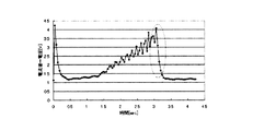
これにより、図5に示されているように、かしめ工具13による継手12のかしめ作業が開始され、このかしめ作業の間、ステップ7(S7)に示されているように、バッテリー19から供給される電流値が電流センサー24によって検出される。このかしめ作業が行われている間のバッテリー19の電流値は、図6に示されているように、時間の経過に伴って次第に上昇し、かしめ作業が完了すると、一端急激に低下する特徴的変化を発生し(図6の破線参照)、その後は一定の出力を示す傾向があるため、図3のステップ8(S8)に示されているように、電流値が急激に低下したかどうかがマイコン25によって判断される。なお、このステップ8(S8)での判定時に検出される電流値の特徴的変化は、継手12のタイプやサイズによって異なることがあるため、予め継手12をかしめた時の電流値の実験値に基づき決定される。
As a result, as shown in FIG. 5, the caulking operation of the joint 12 by the
このステップ8における判定の結果、電流値が急激に低下したと判断された場合には、かしめ工具13による配管36への継手12のかしめ作業が完了したと判断され、次のステップ9(S9)に示されているように、マイコン25によって、バッテリー19からかしめ工具本体17への電力の供給が停止され、PDA14に対して施工完了信号が送信される。一方、前記ステップ8(S8)において、電流値が急激に低下したと判断されなかった場合には、前記ステップ7(S7)に戻り、引き続き電流値が検出される。
As a result of the determination in
次いで、PDA14では、ステップ10(S10)に示されているように、アタッチメント20から送信された施工完了信号を受けて、施工者、施工日時等のかしめ作業の履歴情報が入力され、この履歴情報は、PDA14に保存されると共に、Bluetooth(登録商標)通信によりアタッチメント20の制御装置22に送信される。
Next, as shown in step 10 (S10), the
その後、アタッチメント20では、ステップ11(S11)に示されているように、ICタグ11に前記履歴情報がマイコン25によって自動的に書き込まれる。
Thereafter, in the
また、ホストパソコン15では、ステップ12(S12)に示されているように、PDA14に保存された前記履歴情報が、該履歴情報が書き込まれたICタグ11固有の識別情報に対応付けて本体31のハードディスクにアップロードされて格納され、前記集計用ソフトが起動されることにより、前記識別情報に対応付けて格納された前記履歴情報が、予め格納されたかしめ接合すべき継手の識別情報と対応付けて出力される。
In the host
以降、すべての継手12に対して、上記したのと同様の方法で、かしめ作業が行われる。そして、かしめ作業完了後、スキャニング装置16を施工現場に携帯し、ICタグ11に書き込まれた前記履歴情報を、アンテナ35を介してRFIDリーダー34によって読み取ることにより、かしめ忘れの継手12を発見することができる。
Thereafter, the caulking work is performed on all the
このように上記した本発明の実施の形態に係る配管継手用かしめ忘れ防止システム及びその方法によれば、一連のかしめ作業を行う間に自動的にICタグ11に前記履歴情報が書き込まれるようになっているため、かしめ作業やその確認作業が簡素化されると共に前記履歴情報の書き込み忘れが生じるおそれがない。また、現場事務所のホストパソコン15において、例えば、予め格納されたかしめ接合すべき継手12の識別番号が001〜100の場合に、識別番号001〜095までの継手12のかしめ作業完了のデータしか出力されない場合には、識別番号096〜100の継手がかしめ忘れの可能性があることが分かるように、ICタグ11固有の識別情報に対応付けて格納された前記履歴情報と、予め格納されたかしめ接合すべき継手の識別情報とを対応させて出力させることができる。
さらに、かしめ作業完了後、施工現場において、ICタグ11に書き込まれた前記履歴情報をスキャニング装置16によって読み取ることもできる。したがって、かしめ作業が未施工の継手12があったとしても、現場事務所と現場の両方において、その継手12を容易に発見することができるため、継手12のかしめ忘れを確実に防止し、施工の信頼性を高めることができる。
Thus, according to the above-described caulking forgetting prevention system and method for a pipe joint according to the embodiment of the present invention, the history information is automatically written to the
Further, after the caulking work is completed, the history information written in the
さらに、上記した本発明の実施の形態に係る配管継手用かしめ忘れ防止システム及びその方法によれば、かしめ作業中のバッテリー19の電流値の特徴的変化を検出することによってかしめ作業の完了を判定しているため、かしめ作業の完了を検出するためのスイッチやセンサーなどを、かしめ工具13に取り付ける必要がないため、製造費用や開発費用を抑制することができる。さらにまた、継手12のタイプやサイズの違いによってかしめ作業時のバッテリー19の電流値の特徴的変化が異なる場合であっても、ソフトウェアの変更で簡単に対応することができるため、いろいろなタイプ及びサイズの継手12にも対応することができる。
Furthermore, according to the above-described caulking forgetting prevention system and method for a pipe joint according to the above-described embodiment of the present invention, the completion of caulking work is determined by detecting a characteristic change in the current value of the
10 配管継手用かしめ忘れ防止システム
11 ICタグ
12 継手
13 かしめ工具
14 PDA(端末装置)
15 ホストパソコン(端末装置)
16 スキャニング装置(読取装置)
17 かしめ工具本体
19 バッテリー(駆動用電源)
22 制御装置
25 マイコン
36 配管
10 Piping joint forgetting
15 Host PC (terminal equipment)
16 Scanning device (reading device)
17
22
Claims (6)
前記継手に対応した固有の識別情報が書き込まれた状態で該継手に取り付けられるICタグと、
前記かしめ工具本体に取り付けられ、該かしめ工具本体による前記配管への前記継手のかしめ作業完了後に前記ICタグにかしめ作業の履歴情報を自動的に書き込む制御装置が設けられたアタッチメントと、
を備えていることを特徴とする配管継手用かしめ忘れ防止システム。 A caulking forgetting prevention system for a pipe joint for preventing forgetting caulking of the joint when the caulking joint is joined to the pipe using a dedicated caulking tool,
An IC tag attached to the joint in a state where unique identification information corresponding to the joint is written;
An attachment provided to the caulking tool main body, and provided with a control device that automatically writes caulking work history information to the IC tag after the caulking work of the joint to the pipe by the caulking tool main body is completed;
An anti-caulking system for pipe joints, characterized by comprising:
前記ICタグの識別情報を読み取るための手段と、
該読み取られた前記ICタグの識別情報を予め格納された識別情報と照合し、両者が合致した場合に前記かしめ工具本体に対する駆動用電源からの電力供給を許可する手段と、
を備えている請求項1に記載の配管継手用かしめ忘れ防止システム。 The controller is
Means for reading the identification information of the IC tag;
Means for collating the read identification information of the IC tag with previously stored identification information, and permitting power supply from the driving power source to the caulking tool body when both match,
The caulking-forgetting prevention system for pipe joints according to claim 1, comprising:
前記継手に対応した固有の識別情報が書き込まれた状態で該継手に取り付けられるICタグの前記識別情報を制御装置が読み取る工程と、
該読み取られた前記ICタグの識別情報を予め格納された識別情報と照合し、両者が合致した場合に前記かしめ工具本体に対する駆動用電源からの電力供給を許可する工程と、
前記制御装置が前記かしめ工具の駆動用電源の電流値を検出し、該電流値の特徴的変化を検出した時に前記かしめ工具による前記配管への前記継手のかしめ作業が完了したと判断する工程と、
前記かしめ工具本体によるかしめ作業が完了したと判断した後に前記制御装置が前記ICタグにかしめ作業の履歴情報を自動的に書き込む工程と、
前記ICタグに書き込まれた履歴情報を該ICタグに書き込まれた識別情報に対応付けて端末装置が格納する工程と、
前記書き込まれた識別情報に対応付けて格納された前記履歴情報と、予め格納されたかしめ接合すべき継手の識別情報とを対応させて前記端末装置が出力する工程と、
を備えていることを特徴とする配管継手用かしめ忘れ防止方法。 A caulking forgetting prevention method for a pipe joint for preventing caulking of the joint when the joint is caulked and joined to the pipe using a dedicated caulking tool,
A step in which the control device reads the identification information of the IC tag attached to the joint in a state where unique identification information corresponding to the joint is written;
Collating the read identification information of the IC tag with previously stored identification information, and permitting power supply from the driving power source to the caulking tool body when both match,
A step of determining that the caulking operation of the joint to the pipe by the caulking tool is completed when the control device detects a current value of the driving power source of the caulking tool and detects a characteristic change of the current value; ,
A step of automatically writing the history information of the caulking operation into the IC tag after the control device determines that the caulking operation by the caulking tool body has been completed;
The terminal device stores the history information written in the IC tag in association with the identification information written in the IC tag;
The terminal device outputs the history information stored in association with the written identification information in association with the identification information of the joint to be caulked and stored in advance, and
An anti-caulking method for piping joints, characterized by comprising:
Priority Applications (1)
| Application Number | Priority Date | Filing Date | Title |
|---|---|---|---|
| JP2010074533A JP4999019B2 (en) | 2010-03-29 | 2010-03-29 | Caulking forgetting prevention system and method for piping joints |
Applications Claiming Priority (1)
| Application Number | Priority Date | Filing Date | Title |
|---|---|---|---|
| JP2010074533A JP4999019B2 (en) | 2010-03-29 | 2010-03-29 | Caulking forgetting prevention system and method for piping joints |
Publications (3)
| Publication Number | Publication Date |
|---|---|
| JP2011206783A JP2011206783A (en) | 2011-10-20 |
| JP2011206783A5 JP2011206783A5 (en) | 2011-12-08 |
| JP4999019B2 true JP4999019B2 (en) | 2012-08-15 |
Family
ID=44938466
Family Applications (1)
| Application Number | Title | Priority Date | Filing Date |
|---|---|---|---|
| JP2010074533A Active JP4999019B2 (en) | 2010-03-29 | 2010-03-29 | Caulking forgetting prevention system and method for piping joints |
Country Status (1)
| Country | Link |
|---|---|
| JP (1) | JP4999019B2 (en) |
Families Citing this family (2)
| Publication number | Priority date | Publication date | Assignee | Title |
|---|---|---|---|---|
| JP5546936B2 (en) * | 2010-04-21 | 2014-07-09 | 新菱冷熱工業株式会社 | Electric caulking machine and attachment |
| JP7165161B2 (en) * | 2019-08-09 | 2022-11-02 | 株式会社三五 | Building piping system and construction method of the system |
Family Cites Families (3)
| Publication number | Priority date | Publication date | Assignee | Title |
|---|---|---|---|---|
| JPS6277146A (en) * | 1985-09-28 | 1987-04-09 | Mazda Motor Corp | Deciding method for caulking |
| JP2006155453A (en) * | 2004-12-01 | 2006-06-15 | Nissan Motor Co Ltd | Tool system with installation possibility decision means for component |
| JP4724211B2 (en) * | 2008-08-15 | 2011-07-13 | 株式会社アイオイ・システム | Tightening work support device |
-
2010
- 2010-03-29 JP JP2010074533A patent/JP4999019B2/en active Active
Also Published As
| Publication number | Publication date |
|---|---|
| JP2011206783A (en) | 2011-10-20 |
Similar Documents
| Publication | Publication Date | Title |
|---|---|---|
| US10197422B2 (en) | System and methods for interacting with a smart tool | |
| JP5027017B2 (en) | Work history recording system and method | |
| KR100309378B1 (en) | Apparatus for displaying sms message to real time in digital portable terminal equipment and method therefor | |
| CN106301604B (en) | A kind of radio frequency path detection method and mobile terminal | |
| JP4325592B2 (en) | Facility equipment mapping support system and wireless information terminal | |
| JP4999019B2 (en) | Caulking forgetting prevention system and method for piping joints | |
| US8015421B2 (en) | Power saving apparatus and method for a portable appliance | |
| US10408485B2 (en) | Installation check system | |
| TW200925957A (en) | Function switch methods and systems, and machine readable medium thereof | |
| JP5546936B2 (en) | Electric caulking machine and attachment | |
| JP7108103B2 (en) | Machine teaching terminal used for machine teaching, teaching system, program and safety confirmation method | |
| KR100526609B1 (en) | Data transmission system, data transmission method, data processing device and pointer device | |
| JP2007128128A (en) | Work flow management system | |
| JP5073304B2 (en) | Setup system | |
| JP4583323B2 (en) | Operation support system | |
| JP2008052638A (en) | Electronic appliance and setting system for electronic appliance | |
| JP2011206783A5 (en) | ||
| CN106708512B (en) | Method for starting OTG function of mobile terminal and mobile terminal | |
| JP2007034524A (en) | Information processor, program, and recording medium | |
| JP5030523B2 (en) | Power failure support system | |
| JP2008046786A (en) | Inspection operation system | |
| JP6171770B2 (en) | Electronic equipment | |
| TWI528023B (en) | Torque detection device and method thereof | |
| JP2008293241A (en) | Display device | |
| JP5432125B2 (en) | Civil engineering machinery / equipment with a microcomputer capable of writing individual information |
Legal Events
| Date | Code | Title | Description |
|---|---|---|---|
| A521 | Request for written amendment filed |
Free format text: JAPANESE INTERMEDIATE CODE: A523 Effective date: 20111025 |
|
| TRDD | Decision of grant or rejection written | ||
| A01 | Written decision to grant a patent or to grant a registration (utility model) |
Free format text: JAPANESE INTERMEDIATE CODE: A01 Effective date: 20120508 |
|
| A01 | Written decision to grant a patent or to grant a registration (utility model) |
Free format text: JAPANESE INTERMEDIATE CODE: A01 |
|
| A61 | First payment of annual fees (during grant procedure) |
Free format text: JAPANESE INTERMEDIATE CODE: A61 Effective date: 20120510 |
|
| R150 | Certificate of patent or registration of utility model |
Free format text: JAPANESE INTERMEDIATE CODE: R150 Ref document number: 4999019 Country of ref document: JP Free format text: JAPANESE INTERMEDIATE CODE: R150 |
|
| FPAY | Renewal fee payment (event date is renewal date of database) |
Free format text: PAYMENT UNTIL: 20150525 Year of fee payment: 3 |
|
| R250 | Receipt of annual fees |
Free format text: JAPANESE INTERMEDIATE CODE: R250 |
|
| R250 | Receipt of annual fees |
Free format text: JAPANESE INTERMEDIATE CODE: R250 |
|
| R250 | Receipt of annual fees |
Free format text: JAPANESE INTERMEDIATE CODE: R250 |
|
| R250 | Receipt of annual fees |
Free format text: JAPANESE INTERMEDIATE CODE: R250 |
|
| R250 | Receipt of annual fees |
Free format text: JAPANESE INTERMEDIATE CODE: R250 |
|
| R250 | Receipt of annual fees |
Free format text: JAPANESE INTERMEDIATE CODE: R250 |
|
| R250 | Receipt of annual fees |
Free format text: JAPANESE INTERMEDIATE CODE: R250 |
|
| R250 | Receipt of annual fees |
Free format text: JAPANESE INTERMEDIATE CODE: R250 |
|
| R250 | Receipt of annual fees |
Free format text: JAPANESE INTERMEDIATE CODE: R250 |
|
| R250 | Receipt of annual fees |
Free format text: JAPANESE INTERMEDIATE CODE: R250 |