JP4998317B2 - Relief recording medium manufacturing method and concavo-convex structure data generation apparatus used therefor - Google Patents
Relief recording medium manufacturing method and concavo-convex structure data generation apparatus used therefor Download PDFInfo
- Publication number
- JP4998317B2 JP4998317B2 JP2008038772A JP2008038772A JP4998317B2 JP 4998317 B2 JP4998317 B2 JP 4998317B2 JP 2008038772 A JP2008038772 A JP 2008038772A JP 2008038772 A JP2008038772 A JP 2008038772A JP 4998317 B2 JP4998317 B2 JP 4998317B2
- Authority
- JP
- Japan
- Prior art keywords
- relief
- pixel
- unit
- stereoscopic image
- recording medium
- Prior art date
- Legal status (The legal status is an assumption and is not a legal conclusion. Google has not performed a legal analysis and makes no representation as to the accuracy of the status listed.)
- Expired - Fee Related
Links
Images






Landscapes
- Image Generation (AREA)
Description
本発明は、三次元構造体からなる立体画像の特徴を、表面の凹凸構造として記録したレリーフ記録媒体を製造する方法に関する。また、そのようなレリーフ記録媒体を製造するために利用される凹凸構造データを生成する装置に関する。 The present invention relates to a method for manufacturing a relief recording medium in which the characteristics of a stereoscopic image composed of a three-dimensional structure are recorded as a concavo-convex structure on a surface. The present invention also relates to an apparatus for generating concavo-convex structure data used for manufacturing such a relief recording medium.
カタログ、パンフレット、ポスター、カレンダー、トレーディングカード、包装パッケージ、書籍などの様々な印刷物において、表面に凹凸構造を形成してレリーフ模様を浮き上がらせる手法は古くから用いられている。また、この凹凸構造の表面に金属箔を張りつけた箔押製品も様々な商品として利用されている。このようなレリーフ記録媒体としては、紙の他にも様々な材質のものが利用されている。たとえば、金属製の銘板や樹脂成型品からなる贈答品、土産物、雑貨など様々である。 In various printed materials such as catalogs, brochures, posters, calendars, trading cards, packaging packages, books, etc., a method of forming a relief structure on the surface to raise a relief pattern has been used for a long time. In addition, foil stamping products in which a metal foil is attached to the surface of the concavo-convex structure are also used as various products. As such a relief recording medium, various materials other than paper are used. For example, there are various gifts, souvenirs, miscellaneous goods made of metal nameplates and resin molded products.
このようなレリーフ記録媒体の特徴は、表面の凹凸構造として模様や絵柄となるモチーフが表現されるため、平面的な印刷物に比べて、より立体感のある表現が可能になる点である。もちろん、通常の平面的な印刷物でも、三次元立体を照明環境に配慮して撮影して印刷するようにすれば、ある程度は立体感をもった画像の提示を行うことは可能であるが、そこに再現されている陰影情報は、あくまでも被写体を特定の照明環境で撮影して得られた情報であり、単なる二次元画像にすぎない。これに対して、レリーフ記録媒体では、表面に実際の凹凸構造が形成されているため、より立体感をもった模様や絵柄の表現が可能になる。 A feature of such a relief recording medium is that a motif that becomes a pattern or a picture is expressed as a concavo-convex structure on the surface, so that a more three-dimensional expression can be achieved compared to a planar printed matter. Of course, it is possible to present an image with a certain degree of stereoscopic effect, even if it is a normal flat print, if a 3D solid is taken and printed in consideration of the lighting environment. The shadow information reproduced in the above is information obtained by photographing the subject in a specific lighting environment, and is merely a two-dimensional image. On the other hand, in the relief recording medium, an actual concavo-convex structure is formed on the surface, so that it is possible to express a pattern or a pattern with a more three-dimensional effect.
なお、二次元記録媒体上に三次元画像を記録する方法としては、ホログラムの手法があるが、製造コストが高く、一般的な印刷物に商業的に利用するのには不適当である。また、ホログラム記録媒体の再生像は、あくまでも視覚的にのみ把握される虚像であるのに対して、レリーフ記録媒体上に記録される模様や絵柄は、実在の凹凸構造体であり、触覚的な把握を行うことができる点において、レリーフ記録媒体は固有の利点を有している。 As a method for recording a three-dimensional image on a two-dimensional recording medium, there is a hologram method, but the manufacturing cost is high, and it is not suitable for commercial use for general printed matter. In addition, the reproduced image of the hologram recording medium is a virtual image that can be grasped only visually. On the other hand, the pattern or pattern recorded on the relief recording medium is an actual concavo-convex structure and is tactile. The relief recording medium has an inherent advantage in that it can be grasped.
このようなレリーフ記録媒体を製造する手法として、たとえば、下記の特許文献1には、二値画像に基づいてレリーフ模様となる凹凸構造を作成する手法が開示されており、特許文献2には、階調画像に基づいてレリーフ模様となる凹凸構造を作成する手法が開示されている。更に、特許文献3〜5には、階調画像に基づいてレリーフ模様となる凹凸構造を作成する手法が開示されている。
前掲の各特許文献に開示されている従来技術を利用すれば、原画像として二次元画像を用い、この二次元画像上に表現された模様や絵柄をモチーフとして、レリーフ記録媒体上に凹凸構造を形成することができる。しかしながら、これらの従来技術では、原画像として三次元の立体画像を用いることはできない。 If the conventional techniques disclosed in the above-mentioned patent documents are used, a two-dimensional image is used as an original image, and a concavo-convex structure is formed on a relief recording medium using a pattern or a pattern expressed on the two-dimensional image as a motif. Can be formed. However, these conventional techniques cannot use a three-dimensional stereoscopic image as an original image.
最近は、コンピュータグラフィックス技術の発展により、様々な三次元オブジェクトの立体画像データを容易に入手することができるようになってきている。したがって、任意の立体画像を原画像として利用し、この立体画像の特徴をモチーフとして、レリーフ記録媒体上に凹凸構造を形成することができれば、レリーフとして表現可能な模様や絵柄の自由度は著しく向上する。しかしながら、レリーフ記録媒体の表面に形成される凹凸構造は、その高低差の寸法が限られているため、一般的な立体画像をそのままレリーフ記録媒体に記録することはできない。 Recently, with the development of computer graphics technology, it has become possible to easily obtain stereoscopic image data of various three-dimensional objects. Therefore, if an arbitrary three-dimensional image is used as an original image, and a relief structure can be formed on the relief recording medium using the feature of this three-dimensional image as a motif, the degree of freedom of patterns and patterns that can be expressed as a relief is remarkably improved. To do. However, since the uneven structure formed on the surface of the relief recording medium has a limited height difference, a general stereoscopic image cannot be recorded on the relief recording medium as it is.
たとえば、高さ5cmの物体からなる立体画像を、高低差1mmの凹凸構造をもったレリーフ記録媒体上にそのまま記録するには、従来の手法では、高さ寸法を1/50に縮小して記録するような方法を採らざるを得ないが、このような方法では、もとの物体の特徴を適確に表現することは困難である。 For example, in order to record a stereoscopic image consisting of an object having a height of 5 cm as it is on a relief recording medium having a concavo-convex structure with a height difference of 1 mm, the conventional method reduces the height dimension to 1/50. However, with such a method, it is difficult to accurately represent the characteristics of the original object.
そこで本発明は、原画像として任意の立体画像を用い、この立体画像の特徴をモチーフとして、レリーフ記録媒体上に凹凸構造を形成する手法を提供することを目的とする。 Therefore, an object of the present invention is to provide a method of forming an uneven structure on a relief recording medium using an arbitrary stereoscopic image as an original image and using the characteristics of the stereoscopic image as a motif.
(1) 本発明の第1の態様は、三次元構造体からなる立体画像の特徴を表面の凹凸構造として記録したレリーフ記録媒体を製造する方法において、
XYZ三次元座標系上に、任意の面から構成される立体画像を定義する段階と、
この座標系のXY平面上に、それぞれ単位面からなる画素Pを多数配列することによって構成される二次元画素配列を定義する段階と、
各画素Pの所定位置に、座標値(x,y)をもつサンプル点S(x,y)を定義し、個々の画素Pについて、このサンプル点S(x,y)を通りZ軸に平行な参照直線Lと立体画像を構成する面との交点Q(x,y,z)を求める段階と、
個々の画素Pについて、交点Q(x,y,z)のXY平面からの高さH(x,y)を求める段階と、
凹凸構造の最大高低差D(但し、Dは、立体画像のZ軸方向の最大寸法よりも小さい)を設定する段階と、
個々の画素Pについて、M(x,y)=H(x,y) mod Dなる演算を施し、それぞれ剰余M(x,y)を求める段階と、
個々の画素Pのサンプル点S(x,y)の上方における剰余M(x,y)の高さに位置する上空点QQ(x,y,z)をそれぞれ通るレリーフ構成面を決定する段階と、
レリーフ構成面を媒体表面上に形成する段階と、
を行うようにしたものである。
(1) A first aspect of the present invention is a method for producing a relief recording medium in which features of a three-dimensional image composed of a three-dimensional structure are recorded as a concavo-convex structure on a surface.
Defining a stereoscopic image composed of an arbitrary surface on an XYZ three-dimensional coordinate system;
Defining a two-dimensional pixel array configured by arranging a large number of pixels P each having a unit surface on the XY plane of the coordinate system;
A sample point S (x, y) having a coordinate value (x, y) is defined at a predetermined position of each pixel P, and the individual pixel P passes through this sample point S (x, y) and is parallel to the Z axis. Obtaining an intersection point Q (x, y, z) between a simple reference line L and a plane constituting the stereoscopic image;
Obtaining the height H (x, y) of the intersection point Q (x, y, z) from the XY plane for each pixel P;
Setting a maximum height difference D of the concavo-convex structure (where D is smaller than the maximum dimension of the stereoscopic image in the Z-axis direction);
For each pixel P, performing an operation of M (x, y) = H (x, y) mod D to obtain a remainder M (x, y),
Determining a relief composing surface that passes through each of the sky points QQ (x, y, z) located at the height of the remainder M (x, y) above the sample point S (x, y) of each pixel P; ,
Forming a relief construction surface on the medium surface;
Is to do.
(2) 本発明の第2の態様は、三次元構造体からなる立体画像の特徴を表面の凹凸構造として記録したレリーフ記録媒体を製造する方法において、
XYZ三次元座標系上に、任意の面から構成される立体画像を定義する段階と、
座標系のXY平面上に、それぞれ単位面からなる画素Pを多数配列することによって構成される二次元画素配列を定義する段階と、
各画素Pの所定位置に、座標値(x,y)をもつサンプル点S(x,y)を定義し、個々の画素Pについて、このサンプル点S(x,y)を通りZ軸に平行な参照直線Lと立体画像を構成する面との交点Q(x,y,z)を求める段階と、
個々の画素Pについて、交点Q(x,y,z)のXY平面からの高さH(x,y)を求める段階と、
凹凸構造の最大高低差Dと所定の調整パラメータK(但し、D/Kは、立体画像のZ軸方向の最大寸法よりも小さい)を設定する段階と、
個々の画素Pについて、M(x,y)=(K・H(x,y)) mod Dなる演算を施し、それぞれ剰余M(x,y)を求める段階と、
個々の画素Pのサンプル点S(x,y)の上方における剰余M(x,y)の高さに位置する上空点QQ(x,y,z)をそれぞれ通るレリーフ構成面を決定する段階と、
レリーフ構成面を媒体表面上に形成する段階と、
を行うようにしたものである。
(2) A second aspect of the present invention is a method for producing a relief recording medium in which features of a stereoscopic image composed of a three-dimensional structure are recorded as a concavo-convex structure on a surface.
Defining a stereoscopic image composed of an arbitrary surface on an XYZ three-dimensional coordinate system;
Defining a two-dimensional pixel array configured by arranging a number of pixels P each having a unit surface on an XY plane of a coordinate system;
A sample point S (x, y) having a coordinate value (x, y) is defined at a predetermined position of each pixel P, and the individual pixel P passes through this sample point S (x, y) and is parallel to the Z axis. Obtaining an intersection point Q (x, y, z) between a simple reference line L and a plane constituting the stereoscopic image;
Obtaining the height H (x, y) of the intersection point Q (x, y, z) from the XY plane for each pixel P;
Setting a maximum height difference D of the concavo-convex structure and a predetermined adjustment parameter K (where D / K is smaller than the maximum dimension of the stereoscopic image in the Z-axis direction);
For each pixel P, an operation of M (x, y) = (K · H (x, y)) mod D is performed to obtain a remainder M (x, y),
Determining a relief composing surface that passes through each of the sky points QQ (x, y, z) located at the height of the remainder M (x, y) above the sample point S (x, y) of each pixel P; ,
Forming a relief construction surface on the medium surface;
Is to do.
(3) 本発明の第3の態様は、上述した第1または第2の態様に係るレリーフ記録媒体の製造方法において、
個々の画素Pを構成する各単位面を、当該画素Pについて求められた剰余M(x,y)だけ上方に平行移動し、移動後に得られる単位面をレリーフ単位面PPとし、このレリーフ単位面PPの集合体を用いてレリーフ構成面を決定するようにしたものである。
(3) A third aspect of the present invention is the relief recording medium manufacturing method according to the first or second aspect described above,
Each unit surface constituting each pixel P is translated upward by the remainder M (x, y) obtained for the pixel P, and the unit surface obtained after the movement is defined as a relief unit surface PP. This relief unit surface The relief composing surface is determined using an aggregate of PPs.
(4) 本発明の第4の態様は、上述した第3の態様に係るレリーフ記録媒体の製造方法において、
隣接するレリーフ単位面PP間の境界に生じる段差部に、XY平面に垂直な段差壁面Fを定義し、レリーフ単位面PPと段差壁面Fとの集合体をレリーフ構成面とするようにしたものである。
(4) A fourth aspect of the present invention is the relief recording medium manufacturing method according to the third aspect described above,
A step wall F perpendicular to the XY plane is defined at a step formed at the boundary between adjacent relief unit surfaces PP, and an assembly of the relief unit surface PP and the step wall F is used as a relief constituting surface. is there.
(5) 本発明の第5の態様は、上述した第1または第2の態様に係るレリーフ記録媒体の製造方法において、
個々の画素Pを構成する各単位面を、当該画素Pについて求められた剰余M(x,y)だけ上方に平行移動し、移動後に得られる単位面を傾斜させた面をレリーフ単位面PPとし、このレリーフ単位面PPの集合体を用いてレリーフ構成面を決定するようにしたものである。
(5) A fifth aspect of the present invention is the relief recording medium manufacturing method according to the first or second aspect described above,
Each unit surface constituting each pixel P is translated upward by the remainder M (x, y) obtained for the pixel P, and a surface obtained by inclining the unit surface obtained after the movement is defined as a relief unit surface PP. The relief constituting surface is determined using the assembly of the relief unit surfaces PP.
(6) 本発明の第6の態様は、上述した第1〜第5の態様に係るレリーフ記録媒体の製造方法において、
記録対象となる立体画像を、XYZ三次元座標系上に配置された多数のポリゴンもしくはパラメトリック曲面として定義し、参照直線Lとの交点Q(x,y,z)を、ポリゴンもしくはパラメトリック曲面を示すデータを用いた演算処理によって求めるようにしたものである。
(6) A sixth aspect of the present invention is the relief recording medium manufacturing method according to the first to fifth aspects described above,
A stereoscopic image to be recorded is defined as a large number of polygons or parametric curved surfaces arranged on an XYZ three-dimensional coordinate system, and an intersection Q (x, y, z) with a reference straight line L indicates a polygon or a parametric curved surface. It is obtained by an arithmetic process using data.
(7) 本発明の第7の態様は、上述した第1〜第6の態様に係るレリーフ記録媒体の製造方法において、
個々の画素Pを互いに同一サイズの矩形領域によって構成し、この矩形領域を縦横に隙間なく並べることによって二次元画素配列の定義を行い、各画素Pの中心位置にサンプル点S(x,y)を定義するようにしたものである。
(7) A seventh aspect of the present invention is the relief recording medium manufacturing method according to the first to sixth aspects described above,
Each pixel P is constituted by rectangular regions of the same size, and the rectangular regions are arranged without gaps in the vertical and horizontal directions to define a two-dimensional pixel array, and a sample point S (x, y) is placed at the center position of each pixel P. Is defined.
(8) 本発明の第8の態様は、上述した第1〜第7の態様に係るレリーフ記録媒体の製造方法において、
最大のZ座標値をもつ交点もしくは最小のZ座標値をもつ交点のいずれか一方を統一して選択する選択ルールを予め定めておき、
所定の画素Pについて、参照直線Lに対して交差する面が複数あるために複数の交点が求まる場合には、選択ルールに基づいて選択された単一の交点を、当該画素Pについての交点Q(x,y,z)とするようにしたものである。
(8) An eighth aspect of the present invention is the relief recording medium manufacturing method according to the first to seventh aspects described above,
A selection rule for selecting either the intersection having the maximum Z coordinate value or the intersection having the minimum Z coordinate value in a unified manner is determined in advance.
When a plurality of intersections are obtained for a predetermined pixel P because there are a plurality of planes intersecting the reference straight line L, a single intersection selected based on the selection rule is determined as an intersection Q for the pixel P. (X, y, z).
(9) 本発明の第9の態様は、上述した第1〜第8の態様に係るレリーフ記録媒体の製造方法において、
表面にレリーフ構成面が形成された原版となる媒体を作成した後、当該原版を用いたプレス加工により、多数の媒体を製造するようにしたものである。
(9) A ninth aspect of the present invention is the relief recording medium manufacturing method according to the first to eighth aspects described above,
After a medium serving as an original plate having a relief constituting surface formed on the surface, a large number of media are manufactured by pressing using the original plate.
(10) 本発明の第10の態様は、上述した第9の態様に係るレリーフ記録媒体の製造方法において、
NC工作機械を用いた切削加工により、被加工媒体の表面にレリーフ構成面を形成し、原版となる媒体を作成するようにしたものである。
(10) A tenth aspect of the present invention is the relief recording medium manufacturing method according to the ninth aspect described above,
A relief forming surface is formed on the surface of a medium to be processed by cutting using an NC machine tool, and a medium serving as an original plate is created.
(11) 本発明の第11の態様は、上述した第9の態様に係るレリーフ記録媒体の製造方法において、
表面に被加工媒体を巻き付けた状態で回転駆動する回転ドラムと、強度変調したレーザビームを照射するレーザビーム照射部と、このレーザビームを回転ドラムの回転軸方向に走査する走査部と、を有する製版装置を用いたレーザ加工により、被加工媒体の表面にレリーフ構成面を形成し、原版となる媒体を作成するようにしたものである。
(11) An eleventh aspect of the present invention is the relief recording medium manufacturing method according to the ninth aspect described above,
A rotating drum that is driven to rotate while a workpiece medium is wound around the surface; a laser beam irradiation unit that irradiates an intensity-modulated laser beam; and a scanning unit that scans the laser beam in the rotation axis direction of the rotating drum. A relief forming surface is formed on the surface of a medium to be processed by laser processing using a plate making apparatus, and a medium serving as an original plate is created.
(12) 本発明の第12の態様は、三次元構造体からなる立体画像の特徴を表面の凹凸構造として記録したレリーフ記録媒体を製造するプロセスで用いられるプログラムにおいて、
XYZ三次元座標系上に定義された立体画像Aを示す立体画像データを入力する段階と、
この座標系のXY平面上に、それぞれ単位面からなる画素Pを多数配列することによって構成される二次元画素配列を示すデータを設定する段階と、
各画素Pの所定位置に、座標値(x,y)をもつサンプル点S(x,y)を定義し、個々の画素Pについて、このサンプル点S(x,y)を通りZ軸に平行な参照直線Lと立体画像を構成する面との交点Q(x,y,z)を求める段階と、
個々の画素Pについて、交点Q(x,y,z)のXY平面からの高さH(x,y)を求める段階と、
凹凸構造の最大高低差D(但し、Dは、立体画像のZ軸方向の最大寸法よりも小さい)を設定する段階と、
個々の画素Pについて、M(x,y)=H(x,y) mod Dなる演算を施し、それぞれ剰余M(x,y)を求める段階と、
個々の画素Pのサンプル点S(x,y)の上方における剰余M(x,y)の高さに位置する上空点QQ(x,y,z)をそれぞれ通るレリーフ構成面を決定する段階と、
レリーフ構成面を示すデータを出力する段階と、
をコンピュータに実行させるようにしたものである。
(12) According to a twelfth aspect of the present invention, in a program used in a process for manufacturing a relief recording medium in which features of a three-dimensional image composed of a three-dimensional structure are recorded as a concavo-convex structure on a surface,
Inputting stereoscopic image data indicating the stereoscopic image A defined on the XYZ three-dimensional coordinate system;
Setting data indicating a two-dimensional pixel array configured by arranging a large number of pixels P each having a unit surface on the XY plane of the coordinate system;
A sample point S (x, y) having a coordinate value (x, y) is defined at a predetermined position of each pixel P, and the individual pixel P passes through this sample point S (x, y) and is parallel to the Z axis. Obtaining an intersection point Q (x, y, z) between a simple reference line L and a plane constituting the stereoscopic image;
Obtaining the height H (x, y) of the intersection point Q (x, y, z) from the XY plane for each pixel P;
Setting a maximum height difference D of the concavo-convex structure (where D is smaller than the maximum dimension of the stereoscopic image in the Z-axis direction);
For each pixel P, performing an operation of M (x, y) = H (x, y) mod D to obtain a remainder M (x, y),
Determining a relief composing surface that passes through each of the sky points QQ (x, y, z) located at the height of the remainder M (x, y) above the sample point S (x, y) of each pixel P; ,
Outputting data indicating the relief composition plane;
Is executed by a computer.
(13) 本発明の第13の態様は、三次元構造体からなる立体画像の特徴を表面の凹凸構造として記録したレリーフ記録媒体を製造するプロセスで用いられるプログラムにおいて、
XYZ三次元座標系上に定義された立体画像Aを示す立体画像データを入力する段階と、
この座標系のXY平面上に、それぞれ単位面からなる画素Pを多数配列することによって構成される二次元画素配列を示すデータを設定する段階と、
各画素Pの所定位置に、座標値(x,y)をもつサンプル点S(x,y)を定義し、個々の画素Pについて、このサンプル点S(x,y)を通りZ軸に平行な参照直線Lと立体画像を構成する面との交点Q(x,y,z)を求める段階と、
個々の画素Pについて、交点Q(x,y,z)のXY平面からの高さH(x,y)を求める段階と、
凹凸構造の最大高低差Dと所定の調整パラメータK(但し、D/Kは、立体画像のZ軸方向の最大寸法よりも小さい)を設定する段階と、
個々の画素Pについて、M(x,y)=(K・H(x,y)) mod Dなる演算を施し、それぞれ剰余M(x,y)を求める段階と、
個々の画素Pのサンプル点S(x,y)の上方における剰余M(x,y)の高さに位置する上空点QQ(x,y,z)をそれぞれ通るレリーフ構成面を決定する段階と、
レリーフ構成面を示すデータを出力する段階と、
をコンピュータに実行させるようにしたものである。
(13) According to a thirteenth aspect of the present invention, in a program used in a process for manufacturing a relief recording medium in which features of a three-dimensional image composed of a three-dimensional structure are recorded as a concavo-convex structure on a surface,
Inputting stereoscopic image data indicating the stereoscopic image A defined on the XYZ three-dimensional coordinate system;
Setting data indicating a two-dimensional pixel array configured by arranging a large number of pixels P each having a unit surface on the XY plane of the coordinate system;
A sample point S (x, y) having a coordinate value (x, y) is defined at a predetermined position of each pixel P, and the individual pixel P passes through this sample point S (x, y) and is parallel to the Z axis. Obtaining an intersection point Q (x, y, z) between a simple reference line L and a plane constituting the stereoscopic image;
Obtaining the height H (x, y) of the intersection point Q (x, y, z) from the XY plane for each pixel P;
Setting a maximum height difference D of the concavo-convex structure and a predetermined adjustment parameter K (where D / K is smaller than the maximum dimension of the stereoscopic image in the Z-axis direction);
For each pixel P, an operation of M (x, y) = (K · H (x, y)) mod D is performed to obtain a remainder M (x, y),
Determining a relief composing surface that passes through each of the sky points QQ (x, y, z) located at the height of the remainder M (x, y) above the sample point S (x, y) of each pixel P; ,
Outputting data indicating the relief composition plane;
Is executed by a computer.
(14) 本発明の第14の態様は、上述した第12または第13の態様に係るプログラムにおいて、
個々の画素Pを構成する各単位面を、当該画素Pについて求められた剰余M(x,y)だけ上方に平行移動し、移動後に得られる単位面をレリーフ単位面PPとし、このレリーフ単位面PPの集合体を用いてレリーフ構成面を決定する処理をコンピュータに実行させるようにしたものである。
(14) According to a fourteenth aspect of the present invention, in the program according to the twelfth or thirteenth aspect described above,
Each unit surface constituting each pixel P is translated upward by the remainder M (x, y) obtained for the pixel P, and the unit surface obtained after the movement is defined as a relief unit surface PP. This relief unit surface In this configuration, the computer is caused to execute a process for determining a relief constituent surface using an aggregate of PPs.
(15) 本発明の第15の態様は、上述した第14の態様に係るプログラムにおいて、
隣接するレリーフ単位面PP間の境界に生じる段差部に、XY平面に垂直な段差壁面Fを定義し、レリーフ単位面PPと段差壁面Fとの集合体をレリーフ構成面とする処理をコンピュータに実行させるようにしたものである。
(15) According to a fifteenth aspect of the present invention, in the program according to the fourteenth aspect described above,
A step wall F perpendicular to the XY plane is defined at the step formed at the boundary between adjacent relief unit surfaces PP, and the computer executes the process of making the assembly of the relief unit surface PP and the step wall F into a relief constituent surface. It is made to let you.
(16) 本発明の第16の態様は、上述した第12または第13の態様に係るプログラムにおいて、
個々の画素Pを構成する各単位面を、当該画素Pについて求められた剰余M(x,y)だけ上方に平行移動し、移動後に得られる単位面を傾斜させた面をレリーフ単位面PPとし、このレリーフ単位面PPの集合体を用いてレリーフ構成面を決定する処理をコンピュータに実行させるようにしたものである。
(16) According to a sixteenth aspect of the present invention, in the program according to the twelfth or thirteenth aspect described above,
Each unit surface constituting each pixel P is translated upward by the remainder M (x, y) obtained for the pixel P, and a surface obtained by inclining the unit surface obtained after the movement is defined as a relief unit surface PP. The computer is caused to execute processing for determining the relief constituent surface using the assembly of relief unit surfaces PP.
(17) 本発明の第17の態様は、三次元構造体からなる立体画像の特徴を表面の凹凸構造として記録したレリーフ記録媒体を製造するために利用される、凹凸構造データを生成する装置において、
XYZ三次元座標系上に定義された立体画像を示す立体画像データを格納する立体画像データ格納部と、
この座標系のXY平面上に、それぞれ単位面からなる画素Pを多数配列することによって構成される二次元画素配列を定義するための画素配列データを格納し、各画素Pの所定位置に定義されたサンプル点S(x,y)の位置を示すサンプル点位置データと、各画素Pを構成する単位面を示す画素単位面データと、を提供する画素配列データ提供部と、
サンプル点位置データと立体画像データとに基づいて、個々の画素Pについて、そのサンプル点S(x,y)を通りZ軸に平行な参照直線Lと立体画像を構成する面との交点Q(x,y,z)を求める交点演算部と、
個々の画素Pについて、交点Q(x,y,z)のXY平面からの高さH(x,y)を求める高さ演算部と、
凹凸構造の最大高低差D(但し、Dは、立体画像のZ軸方向の最大寸法よりも小さい)を格納するパラメータ格納部と、
個々の画素Pについて、M(x,y)=H(x,y) mod Dなる演算を施し、それぞれ剰余M(x,y)を求める剰余演算部と、
個々の画素Pを構成する各単位面を、当該画素Pについて求められた剰余M(x,y)だけ上方に平行移動し、移動後に得られる各単位面をそれぞれレリーフ単位面PPとして求めるレリーフ単位面演算部と、
レリーフ単位面PPの集合体を用いてレリーフ構成面を決定し、このレリーフ構成面を示すデータを、レリーフ記録媒体の表面に形成すべき凹凸構造データとして出力するレリーフ構成面作成部と、
を設けるようにしたものである。
(17) A seventeenth aspect of the present invention is an apparatus for generating concavo-convex structure data used for manufacturing a relief recording medium in which features of a three-dimensional image composed of a three-dimensional structure are recorded as a concavo-convex structure on a surface. ,
A stereoscopic image data storage unit for storing stereoscopic image data indicating a stereoscopic image defined on an XYZ three-dimensional coordinate system;
Stores pixel array data for defining a two-dimensional pixel array configured by arranging a large number of pixels P each having a unit surface on the XY plane of the coordinate system, and is defined at a predetermined position of each pixel P. A pixel array data providing unit that provides sample point position data indicating the position of the sample point S (x, y) and pixel unit surface data indicating a unit surface constituting each pixel P;
Based on the sample point position data and the stereoscopic image data, for each pixel P, the intersection point Q () of the reference straight line L passing through the sample point S (x, y) and parallel to the Z axis and the plane constituting the stereoscopic image. x, y, z) intersection calculation unit
A height calculation unit for obtaining the height H (x, y) of the intersection point Q (x, y, z) from the XY plane for each pixel P;
A parameter storage unit that stores a maximum height difference D of the concavo-convex structure (where D is smaller than the maximum dimension of the stereoscopic image in the Z-axis direction);
For each pixel P, a residue calculation unit that performs a calculation of M (x, y) = H (x, y) mod D and obtains a residue M (x, y), respectively,
Relief units in which each unit surface constituting each pixel P is translated upward by the remainder M (x, y) obtained for the pixel P, and each unit surface obtained after the movement is obtained as a relief unit surface PP. A surface calculation unit;
A relief forming surface that determines a relief forming surface using an assembly of relief unit surfaces PP, and outputs data indicating the relief forming surface as concavo-convex structure data to be formed on the surface of the relief recording medium; and
Is provided.
(18) 本発明の第18の態様は、三次元構造体からなる立体画像の特徴を表面の凹凸構造として記録したレリーフ記録媒体を製造するために利用される、凹凸構造データを生成する装置において、
XYZ三次元座標系上に定義された立体画像を示す立体画像データを格納する立体画像データ格納部と、
この座標系のXY平面上に、それぞれ単位面からなる画素Pを多数配列することによって構成される二次元画素配列を定義するための画素配列データを格納し、各画素Pの所定位置に定義されたサンプル点S(x,y)の位置を示すサンプル点位置データと、各画素Pを構成する単位面を示す画素単位面データと、を提供する画素配列データ提供部と、
サンプル点位置データと立体画像データとに基づいて、個々の画素Pについて、そのサンプル点S(x,y)を通りZ軸に平行な参照直線Lと立体画像を構成する面との交点Q(x,y,z)を求める交点演算部と、
個々の画素Pについて、交点Q(x,y,z)のXY平面からの高さH(x,y)を求める高さ演算部と、
凹凸構造の最大高低差Dと所定の調整パラメータK(但し、D/Kは、立体画像のZ軸方向の最大寸法よりも小さい)を格納するパラメータ格納部と、
個々の画素Pについて、M(x,y)=(K・H(x,y)) mod Dなる演算を施し、それぞれ剰余M(x,y)を求める剰余演算部と、
個々の画素Pを構成する各単位面を、当該画素Pについて求められた剰余M(x,y)だけ上方に平行移動し、移動後に得られる各単位面をそれぞれレリーフ単位面PPとして求めるレリーフ単位面演算部と、
レリーフ単位面PPの集合体を用いてレリーフ構成面を決定し、このレリーフ構成面を示すデータを、レリーフ記録媒体の表面に形成すべき凹凸構造データとして出力するレリーフ構成面作成部と、
を設けるようにしたものである。
(18) According to an eighteenth aspect of the present invention, there is provided an apparatus for generating concavo-convex structure data used for manufacturing a relief recording medium in which features of a three-dimensional image composed of a three-dimensional structure are recorded as a concavo-convex structure on a surface. ,
A stereoscopic image data storage unit for storing stereoscopic image data indicating a stereoscopic image defined on an XYZ three-dimensional coordinate system;
Stores pixel array data for defining a two-dimensional pixel array configured by arranging a large number of pixels P each having a unit surface on the XY plane of the coordinate system, and is defined at a predetermined position of each pixel P. A pixel array data providing unit that provides sample point position data indicating the position of the sample point S (x, y) and pixel unit surface data indicating a unit surface constituting each pixel P;
Based on the sample point position data and the stereoscopic image data, for each pixel P, the intersection point Q () of the reference straight line L passing through the sample point S (x, y) and parallel to the Z axis and the plane constituting the stereoscopic image. x, y, z) intersection calculation unit
A height calculation unit for obtaining the height H (x, y) of the intersection point Q (x, y, z) from the XY plane for each pixel P;
A parameter storage unit for storing the maximum height difference D of the concavo-convex structure and a predetermined adjustment parameter K (where D / K is smaller than the maximum dimension of the stereoscopic image in the Z-axis direction);
For each pixel P, a residue calculation unit that performs a calculation of M (x, y) = (K · H (x, y)) mod D and obtains a residue M (x, y),
Relief units in which each unit surface constituting each pixel P is translated upward by the remainder M (x, y) obtained for the pixel P, and each unit surface obtained after the movement is obtained as a relief unit surface PP. A surface calculation unit;
A relief forming surface that determines a relief forming surface using an assembly of relief unit surfaces PP, and outputs data indicating the relief forming surface as concavo-convex structure data to be formed on the surface of the relief recording medium; and
Is provided.
(19) 本発明の第19の態様は、上述した第17または第18の態様に係るレリーフ記録媒体用の凹凸構造データ生成装置において、
立体画像データ格納部が、XYZ三次元座標系上に配置された多数のポリゴンもしくはパラメトリック曲面を示すデータを、立体画像データとして格納するようにしたものである。
(19) According to a nineteenth aspect of the present invention, in the relief structure data generating apparatus for a relief recording medium according to the seventeenth or eighteenth aspect described above,
The stereoscopic image data storage unit stores data indicating a large number of polygons or parametric curved surfaces arranged on an XYZ three-dimensional coordinate system as stereoscopic image data.
(20) 本発明の第20の態様は、上述した第17〜第19の態様に係るレリーフ記録媒体用の凹凸構造データ生成装置において、
画素配列データ提供部が、画素Pを構成する矩形の縦サイズと横サイズを示すデータを画素配列データとして格納しており、この画素Pを縦横に隙間なく並べることによって二次元画素配列の定義を行い、各画素Pの中心位置に定義されたサンプル点S(x,y)の位置を示すサンプル点位置データと、各画素Pを構成する矩形を示す画素単位面データと、を演算によって求めるようにしたものである。
(20) According to a twentieth aspect of the present invention, in the concavo-convex structure data generating apparatus for relief recording media according to the seventeenth to nineteenth aspects described above,
The pixel array data providing unit stores the data indicating the vertical and horizontal sizes of the rectangles constituting the pixel P as pixel array data, and the two-dimensional pixel array is defined by arranging the pixels P vertically and horizontally without any gaps. The sample point position data indicating the position of the sample point S (x, y) defined at the center position of each pixel P and the pixel unit plane data indicating the rectangle constituting each pixel P are obtained by calculation. It is a thing.
(21) 本発明の第21の態様は、上述した第17〜第20の態様に係るレリーフ記録媒体用の凹凸構造データ生成装置において、
交点演算部が、最大のZ座標値をもつ交点もしくは最小のZ座標値をもつ交点のいずれか一方を統一して選択する選択ルールを保持しており、
所定の画素Pについて、参照直線Lに対して交差する面が複数あるために複数の交点が求まる場合には、選択ルールに基づいて選択された単一の交点を、当該画素Pについての交点Q(x,y,z)とするようにしたものである。
(21) According to a twenty-first aspect of the present invention, in the concavo-convex structure data generating apparatus for relief recording media according to the seventeenth to twentieth aspects described above,
The intersection calculation unit holds a selection rule for selecting either the intersection with the maximum Z coordinate value or the intersection with the minimum Z coordinate value in a unified manner,
When a plurality of intersections are obtained for a predetermined pixel P because there are a plurality of planes intersecting the reference straight line L, a single intersection selected based on the selection rule is determined as an intersection Q for the pixel P. (X, y, z).
(22) 本発明の第22の態様は、上述した第17〜第21の態様に係るレリーフ記録媒体用の凹凸構造データ生成装置において、
レリーフ構成面作成部が、隣接するレリーフ単位面PP間の境界に生じる段差部に、XY平面に垂直な段差壁面Fを定義し、レリーフ単位面PPと段差壁面Fとの集合体を示すデータを、レリーフ記録媒体の表面に形成すべき凹凸構造データとして出力するようにしたものである。
(22) According to a twenty-second aspect of the present invention, in the concavo-convex structure data generating apparatus for a relief recording medium according to the seventeenth to twenty-first aspects described above,
The relief forming surface creation unit defines a stepped wall surface F perpendicular to the XY plane at the stepped portion that occurs at the boundary between adjacent relief unit surfaces PP, and data indicating an aggregate of the relief unit surface PP and the stepped wall surface F. The data is output as uneven structure data to be formed on the surface of the relief recording medium.
(23) 本発明の第23の態様は、上述した第17〜第21の態様に係るレリーフ記録媒体用の凹凸構造データ生成装置において、
個々の画素Pを構成する各単位面を、当該画素Pについて求められた剰余M(x,y)だけ上方に平行移動し、移動後に得られる単位面を傾斜させた面をレリーフ単位面PPとし、このレリーフ単位面PPの集合体を用いてレリーフ構成面を決定するようにしたものである。
(23) According to a twenty-third aspect of the present invention, in the relief structure data generating apparatus for relief recording media according to the seventeenth to twenty-first aspects described above,
Each unit surface constituting each pixel P is translated upward by the remainder M (x, y) obtained for the pixel P, and a surface obtained by inclining the unit surface obtained after the movement is defined as a relief unit surface PP. The relief constituting surface is determined using the assembly of the relief unit surfaces PP.
本発明に係るレリーフ記録媒体の製造方法およびこれに用いる凹凸構造データ生成装置によれば、原画像として任意の立体画像を用い、この立体画像の特徴をモチーフとして、レリーフ記録媒体上に凹凸構造を形成することが可能になる。 According to the method for manufacturing a relief recording medium and the concavo-convex structure data generation apparatus used therefor according to the present invention, an arbitrary three-dimensional image is used as an original image, and the concavo-convex structure is formed on the relief recording medium using the feature of the three-dimensional image as a motif. It becomes possible to form.
以下、本発明を図示する実施形態に基づいて説明する。 Hereinafter, the present invention will be described based on the illustrated embodiments.
<<< §1.立体画像をモチーフとするレリーフ記録媒体 >>>
ここでは、まず、立体画像をモチーフとするレリーフ記録媒体を作成する一般的な手順とその問題点を述べておく。
<<< §1. Relief recording medium with 3D image motif >>>
Here, first, a general procedure for creating a relief recording medium using a three-dimensional image as a motif and its problems will be described.
たとえば、図1に示すような立体画像Aをレリーフ記録媒体の表面に記録することを考えてみよう。図示の立体画像Aは、三次元の複雑な構造をもった「やかん」を示す立体画像であり、実際には、その表面を形成する面のデータによって定義することができる(内部構造を示すデータは不要である)。ここでは、この立体画像Aの高さ寸法がGであったとしよう。このような立体画像Aを、レリーフ記録媒体の表面に記録しようとしても、立体情報をそのまま記録することはできない。レリーフ記録媒体は、表面に凹凸構造が形成された三次元物体であるが、当該凹凸構造の最大高低差Dには制限があり(カタログ、パンフレット、ポスター、カレンダーなどの一般的な紙製品の場合、せいぜいD=数mm程度である)、立体画像Aの高さ方向の立体情報をそのまま凹凸構造として記録することはできない。 For example, consider recording a stereoscopic image A as shown in FIG. 1 on the surface of a relief recording medium. The illustrated three-dimensional image A is a three-dimensional image showing a “kettle” having a three-dimensional complex structure, and can actually be defined by the data of the surface forming the surface (data indicating the internal structure). Is not required). Here, it is assumed that the height dimension of the stereoscopic image A is G. Even if such a stereoscopic image A is recorded on the surface of the relief recording medium, the stereoscopic information cannot be recorded as it is. The relief recording medium is a three-dimensional object having a concavo-convex structure formed on the surface, but the maximum height difference D of the concavo-convex structure is limited (in the case of general paper products such as catalogs, brochures, posters, and calendars). At most, D = about several mm), the stereoscopic information in the height direction of the stereoscopic image A cannot be recorded as an uneven structure as it is.
図2は、図1に示す立体画像Aを高さ方向に縮小してレリーフ記録媒体R上に記録した例を示す斜視図である。すなわち、立体画像Aを高さ方向にD/G倍に縮小した立体構造が、レリーフ記録媒体Rの表面に凹凸構造として形成されることになる。このように、高さ方向について縮小すれば、レリーフ記録媒体Rの表面上の凹凸構造の高低差はDに抑えられる。しかしながら、縮小倍率D/Gが小さくなればなるほど、レリーフ記録媒体R上に形成される立体構造体の立体画像Aに対する形状の歪みが増大し、観察者による、もとの立体画像Aの形状把握が困難になる。 FIG. 2 is a perspective view showing an example in which the stereoscopic image A shown in FIG. 1 is reduced and recorded on the relief recording medium R in the height direction. That is, a three-dimensional structure obtained by reducing the three-dimensional image A by D / G times in the height direction is formed as an uneven structure on the surface of the relief recording medium R. Thus, if the height direction is reduced, the height difference of the concavo-convex structure on the surface of the relief recording medium R can be suppressed to D. However, the smaller the reduction ratio D / G, the more the distortion of the shape of the three-dimensional structure formed on the relief recording medium R with respect to the three-dimensional image A, and the observer grasps the shape of the original three-dimensional image A. Becomes difficult.
本発明の根源は、もとの立体画像Aを縮小して媒体上に記録するという手法を採る代わりに、もとの立体画像Aの立体的な形状の特徴を抽出して媒体上に記録するという手法を採るという発想にある。本願発明者は、図1に示すような立体画像Aを上方から観察したときの立体画像A表面各部の面の傾きの情報を抽出し、この傾きの情報を媒体Rの表面上に凹凸構造として記録することにより、立体画像Aを上方から観察した場合の特徴を記録できるのではないかと考えた。以下に述べる手法は、このような基本的な考え方に基づくものである。 The root of the present invention is to extract the feature of the three-dimensional shape of the original stereoscopic image A and record it on the medium instead of taking the method of reducing the original stereoscopic image A and recording it on the medium. The idea is to adopt this method. The inventor of the present application extracts information on the inclination of each part of the surface of the stereoscopic image A when the stereoscopic image A is observed from above as shown in FIG. It was thought that the characteristics when the stereoscopic image A was observed from above could be recorded by recording. The method described below is based on such a basic concept.
結局、本発明では、レリーフ記録媒体R上には、立体画像Aの各部分ごとの面の傾きの情報のみが記録されることになるので、観察者に対して、もとの立体画像Aの全体的な形状を正確に伝達することはできない。しかしながら、カタログ、パンフレット、ポスター、カレンダーなど、一般的な用途に利用されるレリーフ記録媒体の役割は、観察者に対して、何らかの模様や絵柄を提示することにあるので、もとの立体画像Aの特徴に由来する何らかのモチーフが表現されていれば足りる。したがって、以下に述べる本発明に係る手法で作成されるレリーフ記録媒体は、産業上、十分な利用可能性を有するものである。 Eventually, in the present invention, only the information on the tilt of the surface for each part of the stereoscopic image A is recorded on the relief recording medium R. The overall shape cannot be accurately transmitted. However, since the role of relief recording media used for general purposes such as catalogs, brochures, posters, and calendars is to present some pattern or picture to the observer, the original stereoscopic image A It would be enough if any motif derived from the characteristics of was expressed. Therefore, the relief recording medium created by the method according to the present invention described below has sufficient industrial applicability.
<<< §2.本発明に係るレリーフ記録媒体の製造方法の基本概念 >>>
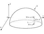
次に、本発明に係るレリーフ記録媒体の製造方法の基本概念を説明する。本発明では、図1に示す「やかん」をモチーフとした立体画像Aのように、任意の三次元構造体からなる立体画像に基づいて、レリーフ記録媒体を製造することが可能である。ただ、ここでは、説明の便宜上、図3に示すように、半球状の立体画像Aを用いてレリーフ記録媒体を製造する単純な例について、本発明の基本概念を説明しよう。
<<< §2. Basic concept of manufacturing method of relief recording medium according to the present invention >>
Next, the basic concept of the method for producing a relief recording medium according to the present invention will be described. In the present invention, a relief recording medium can be manufactured based on a three-dimensional image composed of an arbitrary three-dimensional structure, such as a three-dimensional image A having “kettle” as a motif shown in FIG. However, here, for convenience of explanation, the basic concept of the present invention will be described with respect to a simple example of manufacturing a relief recording medium using a hemispherical stereoscopic image A as shown in FIG.
いま、図3に示すように、XYZ三次元座標系を定義し、この座標系上に半球状の立体画像Aが配置されているものとする。説明の便宜上、この半球状の立体画像Aが、XY平面上に置かれているものとしよう(立体画像Aの円形底面がXY平面に一致するものとする)。ここで、XY平面上における座標値(x,y)をもつサンプル点S(x,y)を定義し、このサンプル点S(x,y)を通りZ軸に平行な参照直線Lと立体画像Aを構成する上面との交点Q(x,y,z)を求め、当該交点Q(x,y,z)のXY平面からの高さH(x,y)を求める。サンプル点S(x,y)は、XY平面上の点であるから、結局、交点Qの高さH(x,y)は、交点QのZ座標値に一致することになるが、ここでは、座標(x,y)で示される位置における立体画像Aの表面の高さを示す値という意味で、H(x,y)という表記を行うことにする。 Now, as shown in FIG. 3, it is assumed that an XYZ three-dimensional coordinate system is defined and a hemispherical stereoscopic image A is arranged on this coordinate system. For convenience of explanation, it is assumed that the hemispherical stereoscopic image A is placed on the XY plane (the circular bottom surface of the stereoscopic image A coincides with the XY plane). Here, a sample point S (x, y) having a coordinate value (x, y) on the XY plane is defined, a reference straight line L passing through the sample point S (x, y) and parallel to the Z axis, and a stereoscopic image An intersection point Q (x, y, z) with the upper surface constituting A is obtained, and a height H (x, y) of the intersection point Q (x, y, z) from the XY plane is obtained. Since the sample point S (x, y) is a point on the XY plane, the height H (x, y) of the intersection point Q eventually coincides with the Z coordinate value of the intersection point Q. , H (x, y) is used to mean a value indicating the height of the surface of the stereoscopic image A at the position indicated by the coordinates (x, y).
一方、この座標系のXY平面上に、図4に示すような二次元画素配列を定義する。ここでは、この二次元画素配列の構成要素となる1つの画素を、P(i,j)で示すことにする。ここで、iは当該画素が位置する配列の行数を示し、jは当該画素が位置する配列の列数を示している。したがって、画素P(i,j)は、この二次元画素配列の第i行・第j列目に位置する画素ということになる。たとえば、図の左上に示した画素P(2,3)は、第2行・第3列目の画素である。画素P(2,3)は、図にハッチングを施して示すように、正方形状の単位面から構成されている。 On the other hand, a two-dimensional pixel array as shown in FIG. 4 is defined on the XY plane of this coordinate system. Here, one pixel that is a component of the two-dimensional pixel array is denoted by P (i, j). Here, i represents the number of rows in the array in which the pixel is located, and j represents the number of columns in the array in which the pixel is located. Accordingly, the pixel P (i, j) is a pixel located in the i-th row and j-th column of this two-dimensional pixel array. For example, the pixel P (2, 3) shown in the upper left of the figure is the pixel in the second row and the third column. The pixel P (2, 3) is composed of a square unit surface as shown by hatching in the figure.
このように、図示の例では、個々の画素P(i,j)は正方形状の単位面から構成されているが、画素を構成する単位面の形状は任意でかまわない。要するに、XY平面上に、それぞれ任意形状をもった単位面からなる画素Pを多数配列することにより、二次元画素配列が定義されていればよい。もっとも、実用上は、個々の画素Pを互いに同一サイズの矩形領域によって構成し、この矩形領域を縦横に隙間なく並べることによって二次元画素配列の定義を行うのが好ましい。 As described above, in the illustrated example, each pixel P (i, j) is formed of a square unit surface, but the shape of the unit surface forming the pixel may be arbitrary. In short, it is only necessary to define a two-dimensional pixel array by arranging a large number of pixels P each having a unit surface having an arbitrary shape on the XY plane. However, in practice, it is preferable to define the two-dimensional pixel array by configuring the individual pixels P by rectangular regions of the same size and arranging the rectangular regions vertically and horizontally without any gaps.
そして、個々の画素P(i,j)内にそれぞれサンプル点Sを定義する。画素P(i,j)内に定義されたサンプル点はS(i,j)と表記することも可能であるが、ここでは、各サンプル点は、XY座標系における何らかの座標値(x,y)をもった点であるため、サンプル点S(x,y)と表記することにする。ここでは、図4に示すように、各画素P(i,j)の中心位置にサンプル点S(x,y)を定義した例を示すが、個々のサンプル点Sの位置は、個々の画素Pを構成する単位面内の任意の位置(単位面を構成する領域の境界線上でもよい)でかまわない。たとえば、図4に示す正方形状の各画素Pの左上隅点に、当該画素のサンプル点Sを定義してもよい。 A sample point S is defined in each pixel P (i, j). The sample point defined in the pixel P (i, j) can also be expressed as S (i, j). Here, each sample point has some coordinate value (x, y in the XY coordinate system). ), It is expressed as a sample point S (x, y). Here, as shown in FIG. 4, an example in which a sample point S (x, y) is defined at the center position of each pixel P (i, j) is shown, but the position of each sample point S is the individual pixel. It may be at an arbitrary position in the unit surface constituting P (may be on the boundary line of the region constituting the unit surface). For example, the sample point S of the pixel may be defined at the upper left corner of each square pixel P shown in FIG.
さて、図3で説明したように、XY平面上の任意のサンプル点S(x,y)について、当該サンプル点S(x,y)を通りZ軸に平行な参照直線Lと立体画像Aを構成する面との交点Q(x,y,z)を求め、当該交点Q(x,y,z)のXY平面からの高さH(x,y)を求めることができるので、図4に示す個々の画素P(i,j)について、それぞれサンプル点S(x,y)の位置における立体画像Aの上面の高さH(x,y)を求めることができる。なお、上方に立体画像Aが存在せずに、交点Qが存在しない画素については、たとえば、高さH(x,y)=0のように、便宜的に何らかの高さを定義しておけばよい。 Now, as described with reference to FIG. 3, for an arbitrary sample point S (x, y) on the XY plane, a reference straight line L and a stereoscopic image A that pass through the sample point S (x, y) and are parallel to the Z axis are displayed. Since the intersection point Q (x, y, z) with the constituting surface can be obtained and the height H (x, y) from the XY plane of the intersection point Q (x, y, z) can be obtained, FIG. For each pixel P (i, j) shown, the height H (x, y) of the upper surface of the stereoscopic image A at the position of the sample point S (x, y) can be obtained. For a pixel in which the stereoscopic image A does not exist above and the intersection point Q does not exist, a certain height is defined for convenience, for example, height H (x, y) = 0. Good.
こうして各画素ごとに求められた高さH(x,y)を、当該画素の画素値とすれば、このような画素値をもった画素の集合体からなるデータは、形式的には二次元画像データの形態をとるが、その実体は、三次元の立体画像を示すデータになる。もっとも、1つの画素には、1つの高さを示す画素値しか定義できないので、表現可能な立体画像の形状は制限を受けることになる。たとえば、図3に示すような半球状の立体画像Aを表現することはできるが、完全な球状の立体画像を表現することはできない。このように、高さの値を画素値にもつ二次元画素配列からなるデータは、一般に、Height Field データと呼ばれている。 If the height H (x, y) obtained for each pixel in this way is used as the pixel value of the pixel, data consisting of an aggregate of pixels having such a pixel value is formally two-dimensional. Although it takes the form of image data, the entity is data indicating a three-dimensional stereoscopic image. However, since only one pixel value indicating one height can be defined for one pixel, the shape of a stereoscopic image that can be expressed is limited. For example, a hemispherical stereoscopic image A as shown in FIG. 3 can be expressed, but a complete spherical stereoscopic image cannot be expressed. As described above, data composed of a two-dimensional pixel array having a height value as a pixel value is generally called height field data.
本発明は、このようなHeight Field データで表現される三次元構造体からなる立体画像をモチーフとして、その特徴をレリーフ記録媒体の表面に凹凸構造として記録することを前提とした技術である。上述したとおり、このHeight Field データは、XYZ三次元座標系におけるXY平面上に配列された多数の画素からなる二次元画素配列から構成され、個々の画素にはZ軸に沿った高さを示す画素値Hが定義されており、この画素値Hにより三次元構造体が表現された立体画像データということができる。 The present invention is a technique based on the premise that a three-dimensional image composed of a three-dimensional structure represented by such height field data is used as a motif and the characteristics are recorded as a concavo-convex structure on the surface of a relief recording medium. As described above, this height field data is composed of a two-dimensional pixel array composed of a large number of pixels arranged on the XY plane in the XYZ three-dimensional coordinate system, and each pixel indicates a height along the Z axis. A pixel value H is defined, and it can be said that it is stereoscopic image data in which a three-dimensional structure is expressed by the pixel value H.
続いて、レリーフ記録媒体の表面に形成する凹凸構造の最大高低差Dを決定する。この最大高低差Dは、たとえば、図2に示す例のように、レリーフを構成する凹凸構造の最大高さに相当する寸法であり、前述したように、カタログ、パンフレット、ポスター、カレンダーなどの一般的な紙製品の場合、せいぜいD=数mm程度である。一方、図1に示すように、モチーフとして用いる「やかん」を示す立体画像の高さGは、G>Dである(G≦Dの場合、そもそも本発明に係る工夫を施す必要はない)。したがって、ここで設定する最大高低差Dは、モチーフとして用いる立体画像(三次元構造体)のZ軸方向の最大寸法よりも小さいことが前提となる。 Subsequently, the maximum height difference D of the uneven structure formed on the surface of the relief recording medium is determined. This maximum height difference D is, for example, a dimension corresponding to the maximum height of the concavo-convex structure constituting the relief as in the example shown in FIG. 2, and as described above, it is common for catalogs, brochures, posters, calendars, etc. In the case of typical paper products, D is at most about several millimeters. On the other hand, as shown in FIG. 1, the height G of the stereoscopic image indicating “kettle” used as the motif is G> D (if G ≦ D, there is no need to devise the invention according to the present invention). Accordingly, it is assumed that the maximum height difference D set here is smaller than the maximum dimension in the Z-axis direction of a stereoscopic image (three-dimensional structure) used as a motif.
最大高低差Dが定まったら、上述した立体画像データ(Height Field データ)を構成する個々の画素の画素値Hに対して、M=H mod Dなる演算を施し、画素値Hを新たな画素値Mに置き換えた二次元画素配列から構成される置換画像データを求める。たとえば、第i行・第j列目に位置する画素P(i,j)については、その画素値H(x,y)を用いた「M(x,y)=H(x,y) mod D」なる演算により、新たな画素値M(x,y)が求められる。置換画像データは、すべての画素についての画素値Hを新たな画素値Mに置き換えることによって得られる。ここで、「mod」は剰余を求めるための演算子であり、「H(x,y) mod D」は、H(x,y)の値をDで除したときの剰余を示している。したがって、新たな画素値M(x,y)は、H(x,y)の値をDで除したときの剰余を示している。 When the maximum height difference D is determined, an operation of M = H mod D is performed on the pixel value H of each pixel constituting the above-described stereoscopic image data (Height Field data), and the pixel value H is set as a new pixel value. Replacement image data composed of the two-dimensional pixel array replaced with M is obtained. For example, for the pixel P (i, j) located in the i-th row and j-th column, “M (x, y) = H (x, y) mod using the pixel value H (x, y)”. A new pixel value M (x, y) is obtained by the calculation “D”. The replacement image data is obtained by replacing the pixel value H for all the pixels with a new pixel value M. Here, “mod” is an operator for obtaining a remainder, and “H (x, y) mod D” represents a remainder when the value of H (x, y) is divided by D. Therefore, the new pixel value M (x, y) indicates the remainder when the value of H (x, y) is divided by D.
図5は、図3の正面図であり、縦方向に引いた多数の実線は、この半球のY軸に平行な直径上に並んだ各サンプル点S(x,y)の位置に立てた垂線(Z軸に平行な線)を示しており、その上端は、半球状の立体画像Aの上面位置となっている。別言すれば、これら垂線の下端はサンプル点S(x,y)の位置となり、上端は交点Q(x,y,z)の位置となり、その長さは、高さH(x,y)に対応する。一方、図5において、横方向に引いた水平破線は、Dの整数倍の位置を示している。各画素についての剰余M(x,y)は、当該画素内のサンプル点S(x,y)の位置に立てた垂線が交差する水平破線のうち、最も上方にある水平破線より上の半端な部分の長さということになる。 FIG. 5 is a front view of FIG. 3, and a large number of solid lines drawn in the vertical direction are perpendicular to the positions of the sample points S (x, y) arranged on the diameter parallel to the Y axis of the hemisphere. (Line parallel to the Z-axis) is shown, and the upper end thereof is the upper surface position of the hemispherical stereoscopic image A. In other words, the lower end of these perpendiculars is the position of the sample point S (x, y), the upper end is the position of the intersection point Q (x, y, z), and its length is the height H (x, y). Corresponding to On the other hand, in FIG. 5, a horizontal broken line drawn in the horizontal direction indicates a position that is an integral multiple of D. The remainder M (x, y) for each pixel is the half above the uppermost horizontal broken line among the horizontal broken lines intersected by the vertical lines standing at the position of the sample point S (x, y) in the pixel. That is the length of the part.
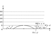
図6は、各サンプル点S(x,y)の垂直上方に、上空点QQ(x,y,z)をプロットした状態を示す正面図である。ここで、上空点QQ(x,y,z)は、サンプル点S(x,y)の上方における、図5に示す剰余M(x,y)の高さに位置する点である。剰余M(x,y)<最大高低差Dであるから、図6に示すように、各上空点QQ(x,y,z)は、Z軸上の0〜Dの区間内に位置することになり、Z軸上のD〜5Dの区間内には存在しない。 FIG. 6 is a front view showing a state in which the sky point QQ (x, y, z) is plotted vertically above each sample point S (x, y). Here, the sky point QQ (x, y, z) is a point located at the height of the remainder M (x, y) shown in FIG. 5 above the sample point S (x, y). Since the remainder M (x, y) <the maximum height difference D, as shown in FIG. 6, each upper empty point QQ (x, y, z) must be located in the 0 to D section on the Z axis. And does not exist in the section of D to 5D on the Z-axis.
結局、図5に示す半球状の立体画像Aを示す立体画像データ(Height Field データ)を構成する個々の画素の画素値Hを、新たな画素値M(剰余M)に置き換えることにより得られる置換画像データは、図6に示す上空点QQ(x,y,z)の集合体からなる新たな立体画像を示すデータということになる。そこで、XY平面に沿って置かれた媒体の表面上に、この置換画像データの各画素値Mに応じた高さをもつ凹凸構造からなるレリーフ構成面を形成すれば、個々の上空点QQ(x,y,z)をそれぞれ通るレリーフ構成面が形成されたレリーフ記録媒体を得ることができる。 After all, the replacement obtained by replacing the pixel value H of each pixel constituting the stereoscopic image data (Height Field data) indicating the hemispherical stereoscopic image A shown in FIG. 5 with a new pixel value M (residue M). The image data is data indicating a new three-dimensional image composed of an aggregate of the sky points QQ (x, y, z) shown in FIG. Therefore, if a relief composing surface having a concavo-convex structure having a height corresponding to each pixel value M of the replacement image data is formed on the surface of the medium placed along the XY plane, the individual sky points QQ ( It is possible to obtain a relief recording medium on which relief constituting surfaces that pass through x, y, z) are formed.
図7は、図6に示す各上空点QQ(x,y,z)を通るレリーフ構成面Bを表面に形成したレリーフ記録媒体Rを示す縦断面図である。レリーフ構成面Bは、図6に示す各上空点QQ(x,y,z)を連結する凹凸面になる。図示の例の場合、Z=−Eなる式で示される平面上に、このレリーフ記録媒体Rの底面が位置しており、レリーフを構成する凹凸構造は、Z=Dなる式で示される平面と、Z=0なる式で示される平面(XY平面)との間に形成されている。ここでDは、前述のように設定した「レリーフ記録媒体Rに形成する凹凸構造の最大高低差」であり、Eは、「レリーフ記録媒体Rの基体部の厚み」ということになる。 FIG. 7 is a longitudinal sectional view showing a relief recording medium R having a relief constituting surface B formed on the surface thereof passing through the upper empty points QQ (x, y, z) shown in FIG. The relief constituting surface B is an uneven surface that connects the upper empty points QQ (x, y, z) shown in FIG. In the case of the illustrated example, the bottom surface of the relief recording medium R is located on the plane represented by the equation Z = −E, and the concavo-convex structure constituting the relief is the plane represented by the equation Z = D. , Z = 0, and a plane (XY plane) represented by the equation of Z = 0. Here, D is the “maximum height difference of the concavo-convex structure formed on the relief recording medium R” set as described above, and E is “the thickness of the base portion of the relief recording medium R”.
図7に示すレリーフ記録媒体Rの上面を形成するレリーフ構成面Bと、図5に示す半球状の立体画像Aの上面とを比較すると、全体的な形状は全く異なっているが、図5に示す立体画像Aの上面の各部の傾斜に関する情報が、図7に示すレリーフ構成面Bの部分部分に表現されていることがわかる。すなわち、図7に示すレリーフ構成面Bには、原画像として用いられた半球状の立体画像Aの特徴をモチーフとした凹凸構造が形成されていることになり、レリーフ記録媒体Rに記録されているレリーフのデザインには、半球状の立体画像Aの特徴が反映されていることになる。 When the relief constituting surface B forming the upper surface of the relief recording medium R shown in FIG. 7 is compared with the upper surface of the hemispherical stereoscopic image A shown in FIG. 5, the overall shape is completely different. It can be seen that the information regarding the inclination of each part of the upper surface of the stereoscopic image A shown is expressed in the partial portion of the relief constituting surface B shown in FIG. That is, the relief structure surface B shown in FIG. 7 has a concavo-convex structure with the motif of the hemispherical stereoscopic image A used as the original image, and is recorded on the relief recording medium R. The feature of the hemispherical stereoscopic image A is reflected in the relief design.
なお、図6に示すように、各画素の上方にそれぞれ上空点QQ(x,y,z)が定義された後に、これら個々の上空点QQ(x,y,z)を通るレリーフ構成面を形成する方法の一例としては、たとえば、個々の上空点QQ(x,y,z)を滑らかに連結するような自由曲面を演算によって求める手法を採ることが可能である。一般に、三次元空間上に配置された複数の任意点を滑らかに連結するような自由曲面は、ベジェ曲面やスプライン曲面など、様々な曲面が知られており、これらの曲面を演算によって求める手法も様々なものが知られている。したがって、図6に示す個々の上空点QQ(x,y,z)の座標値が得られれば、これら座標値を用いた演算により、図7に示すようなレリーフ構成面Bを求めることができる。もちろん、この場合、必ずしも全上空点QQ(x,y,z)の位置を正確に通る自由曲面を求める必要はなく、多少の誤差が生じてもかまわない。 As shown in FIG. 6, after the upper sky points QQ (x, y, z) are defined above the respective pixels, the relief constituent planes passing through these upper sky points QQ (x, y, z) are shown. As an example of the forming method, for example, it is possible to employ a method of calculating a free-form surface that smoothly connects the individual sky points QQ (x, y, z). In general, various free-form surfaces such as Bezier surfaces and spline surfaces are known as free-form surfaces that smoothly connect a plurality of arbitrary points arranged in a three-dimensional space. Various things are known. Therefore, if the coordinate values of the individual sky points QQ (x, y, z) shown in FIG. 6 are obtained, the relief constituting surface B as shown in FIG. 7 can be obtained by calculation using these coordinate values. . Of course, in this case, it is not always necessary to obtain a free-form surface that accurately passes through the positions of all the sky points QQ (x, y, z), and some errors may occur.
ただ、そのような自由曲面を求める演算は、通常、コンピュータに多大な負荷を課することになり、また、そのような自由曲面からなるレリーフ構成面Bを、実際の物理的な媒体の表面上に形成する際にも、加工作業上の技術的な負担は大きい。そこで、実用上は、次のような簡便な方法で、レリーフ構成面Bを求めるようにするのが好ましい。 However, the calculation for obtaining such a free-form surface usually imposes a heavy load on the computer, and the relief constituting surface B composed of such a free-form surface is placed on the surface of an actual physical medium. The technical burden on the processing work is also great when forming the film. Therefore, in practice, it is preferable to obtain the relief constituting surface B by the following simple method.
ここで述べる簡便な方法は、XY平面上に定義した画素P(i,j)を構成する単位面を、当該画素P(i,j)について求められた剰余M(x,y)だけ上方に(Z軸方向に)平行移動し、移動後に得られる単位面をレリーフ単位面PPとし、このレリーフ単位面PPの集合体を用いてレリーフ構成面Bを決定する方法である。 The simple method described here is such that the unit surface constituting the pixel P (i, j) defined on the XY plane is moved upward by the remainder M (x, y) obtained for the pixel P (i, j). In this method, the unit surface obtained after translation is moved in the Z-axis direction and the unit surface obtained after the movement is used as the relief unit surface PP, and the relief constituting surface B is determined using the aggregate of the relief unit surfaces PP.
図8は、図7に示すレリーフ構成面Bを、このような簡便な方法で形成した場合の部分拡大図である。図8のY軸上に示す太線部分は、XY平面上に定義された画素P(i,j)の単位面であり、その上方に示されているPP(i,j)は、この単位面を上方に剰余M(x,y)だけ平行移動することにより得られたレリーフ単位面である。ここに示す例の場合、サンプル点S(x,y)は、画素P(i,j)の中心点であるから、上空点QQ(x,y,z)は、レリーフ単位面PP(i,j)の中心点になる。 FIG. 8 is a partially enlarged view when the relief constituting surface B shown in FIG. 7 is formed by such a simple method. The thick line portion shown on the Y axis in FIG. 8 is a unit surface of the pixel P (i, j) defined on the XY plane, and PP (i, j) shown above is the unit surface. Is a relief unit surface obtained by translating upward by a remainder M (x, y). In the example shown here, since the sample point S (x, y) is the center point of the pixel P (i, j), the sky point QQ (x, y, z) is the relief unit plane PP (i, j) becomes the center point.
結局、図4の二次元画素配列上に示す個々の画素P(i,j)の単位面(この例は、正方形の領域)が四角いタイルであるとすれば、これら個々のタイルを、Z軸方向(図4の紙面垂直上方)に、それぞれ剰余M(x,y)だけ平行移動して固定することにより、レリーフ構造面Bが得られることになる。この場合、移動後の個々のタイルが、それぞれレリーフ単位面PPということになる。ただ、隣接するレリーフ単位面PP間の境界には段差部が生じるので、この段差部には、XY平面に垂直な段差壁面Fを定義し、レリーフ単位面PPと段差壁面Fとの集合体をレリーフ構成面Bとする。図8において、隣接するレリーフ単位面PP間を連結している破線は、この段差壁面Fを示しており、水平方向の実線で示されているレリーフ単位面PPと、垂直方向の破線で示されている段差壁面Fとの集合体が、レリーフ構成面Bを形成していることになる。 After all, if the unit plane (in this example, a square area) of each pixel P (i, j) shown on the two-dimensional pixel array in FIG. The relief structure plane B is obtained by moving in parallel in the direction (upper right direction in FIG. 4) by the remainder M (x, y). In this case, each tile after movement is a relief unit plane PP. However, since a step portion is formed at the boundary between adjacent relief unit surfaces PP, a step wall surface F perpendicular to the XY plane is defined in this step portion, and an aggregate of the relief unit surface PP and the step wall surface F is defined. Let it be a relief constituting surface B. In FIG. 8, a broken line connecting adjacent relief unit surfaces PP indicates the stepped wall surface F, and is indicated by a relief unit surface PP indicated by a solid line in the horizontal direction and a broken line in the vertical direction. The assembly with the stepped wall surface F is forming the relief constituting surface B.
このような簡便な方法を採ると、レリーフ構成面Bは、滑らかな曲面にはならず、段差構造をもった多数の平面の集合体によって構成されることになるが、1つの画素P(i,j)の縦横寸法を十分に小さく設定すれば、各レリーフ単位面PPも非常に微小な平面領域となるので、実用上は問題は生じない。たとえば、1つの画素P(i,j)を、一辺が100μmの正方形に設定すれば、各レリーフ単位面PP(i,j)も一辺が100μmの正方形になるので、肉眼でレリーフ構成面Bを観察する限り、図7に示すような滑らかな曲面として観察されることになる。 When such a simple method is adopted, the relief constituting surface B does not become a smooth curved surface, but is constituted by an aggregate of a large number of planes having a step structure, but one pixel P (i , J) if the vertical and horizontal dimensions are set to be sufficiently small, each relief unit surface PP also becomes a very small planar region, so that there is no practical problem. For example, if one pixel P (i, j) is set to a square with a side of 100 μm, each relief unit surface PP (i, j) also becomes a square with a side of 100 μm. As long as the observation is performed, a smooth curved surface as shown in FIG. 7 is observed.
<<< §3.本発明に係るレリーフ記録媒体の製造方法の具体的手順 >>>
図9は、本発明に係るレリーフ記録媒体の製造方法の手順を示す流れ図であり、三次元構造体からなる立体画像の特徴を表面の凹凸構造として記録したレリーフ記録媒体を製造するプロセスが示されている。
<<< §3. Specific Procedure for Manufacturing Method of Relief Recording Medium According to the Present Invention >>
FIG. 9 is a flowchart showing the procedure of the method for manufacturing a relief recording medium according to the present invention, and shows a process for manufacturing a relief recording medium in which features of a three-dimensional image composed of a three-dimensional structure are recorded as a surface uneven structure. ing.
この流れ図におけるステップS1〜S4の手順は、前述した「Height Field データ」を作成する手順であり、ステップS5〜S8の手順は、この「Height Field データ」を構成する個々の画素の画素値H(x,y)を、剰余M(x,y)に置換し、レリーフ構成面を作成する手順である。このステップS1〜S8の手順は、設計者が手作業や計算機を利用して実行することも可能であるが、実用上は、これらの各手順を実行する専用プログラムを用意し、当該プログラムを組み込んだコンピュータによって実行させることになる。したがって、ステップS1〜S8の処理は、実際には、コンピュータによって実行される処理ということになる。 The procedure of steps S1 to S4 in this flowchart is a procedure for creating the above-mentioned “Height Field data”, and the procedure of steps S5 to S8 is the pixel value H () of each pixel constituting this “Height Field data”. In this procedure, x, y) is replaced with the remainder M (x, y) to create a relief composing surface. The steps S1 to S8 can be executed manually by a designer or using a computer. However, in practice, a dedicated program for executing each of these steps is prepared and the program is incorporated. It will be executed by a computer. Therefore, the processing in steps S1 to S8 is actually processing executed by a computer.
これに対して、最後のステップS9は、このコンピュータから出力される凹凸構造データを利用して、物理的な媒体の表面に凹凸構造を形成する工程であり、何らかの加工装置を用いて行われるプロセスになる。このステップS9の具体的なプロセスについては後述する。 On the other hand, the final step S9 is a process of forming a concavo-convex structure on the surface of a physical medium using the concavo-convex structure data output from the computer, and is a process performed using some processing apparatus. become. A specific process in step S9 will be described later.
さて、まずステップS1において、XYZ三次元座標系上に、立体画像Aを定義する段階が行われる。この立体画像Aは、原画像となる仮想物体であり、この仮想物体の表面形状の特徴(各部の面の傾きの情報)が抽出され、記録媒体Rの表面上に凹凸構造として記録されることになる。前述した§2では、便宜上、非常に単純は半球状の立体画像Aを用いた説明を行ったが、ここでは、図10に示すように、XYZ三次元座標系上に、「やかん」を示す立体画像Aが定義されたものとしよう。上述したとおり、本発明で用いられる立体画像Aは、その表面が定義されていれば足り、内部構造の定義は不要である。 First, in step S1, a step of defining a stereoscopic image A on the XYZ three-dimensional coordinate system is performed. The stereoscopic image A is a virtual object that becomes an original image, and the surface shape features (information on the inclination of the surface of each part) of the virtual object are extracted and recorded as an uneven structure on the surface of the recording medium R. become. In §2 described above, for the sake of convenience, explanation was given using a hemispherical stereoscopic image A very simply, but here, as shown in FIG. 10, "Kettle" is shown on the XYZ three-dimensional coordinate system. Let us assume that stereoscopic image A is defined. As described above, it is sufficient that the surface of the stereoscopic image A used in the present invention is defined, and the definition of the internal structure is unnecessary.
コンピュータ上での立体画像Aの定義は、立体画像Aを示す三次元形状データをコンピュータ内の格納場所に格納することによって行われる。通常、コンピュータグラフィックスの分野では、三次元の立体画像は、XYZ三次元座標系上に配置された多数のポリゴンもしくはパラメトリック曲面として定義される。本発明においても、このようなポリゴンもしくはパラメトリック曲面を示すデータによって、立体画像Aを定義することができる。 The definition of the stereoscopic image A on the computer is performed by storing the three-dimensional shape data indicating the stereoscopic image A in a storage location in the computer. Usually, in the field of computer graphics, a three-dimensional stereoscopic image is defined as a large number of polygons or parametric curved surfaces arranged on an XYZ three-dimensional coordinate system. Also in the present invention, the stereoscopic image A can be defined by data indicating such polygons or parametric curved surfaces.
続くステップS2では、このXYZ三次元座標系におけるXY平面上に、それぞれ単位面からなる画素Pを多数配列することによって構成される二次元画素配列を定義する段階が行われる。個々の画素Pは、それぞれが単位面を構成していれば、どのような大きさ、どのような形状のものであってもかまわない。もちろん、個々の画素の大きさや形状が、それぞれ異なっていてもかまわないし、これらの画素をどのように並べて二次元画素配列を定義してもかまわない。ただ、後のステップにおける演算負担を軽減するために、実用上は、個々の画素Pを互いに同一サイズの矩形領域によって構成し、この矩形領域を縦横に隙間なく並べることによって二次元画素配列の定義を行うようにするのが好ましい。 In the subsequent step S2, a step of defining a two-dimensional pixel array configured by arranging a large number of pixels P each having a unit surface on the XY plane in the XYZ three-dimensional coordinate system is performed. The individual pixels P may have any size and any shape as long as each pixel P constitutes a unit surface. Of course, the size and shape of the individual pixels may be different from each other, and the two-dimensional pixel array may be defined by arranging these pixels. However, in order to reduce the calculation burden in the subsequent steps, in practice, each pixel P is composed of rectangular regions of the same size, and the rectangular regions are arranged vertically and horizontally without any gaps, thereby defining a two-dimensional pixel array. It is preferable to carry out.
図10に示す例では、XY平面上に正方形状をした画素Pを縦横にマトリックス状に隙間なく並べることによって二次元画素配列の定義が行われた例が示されている。図に示す画素P(i,j)は、この二次元画素配列におけるi行j列目の画素である。コンピュータ上で、このような二次元画素配列を定義するには、1つの画素Pの寸法(正方形状の画素の場合は、その一辺の長さ)を示すデータをコンピュータ内の格納場所に格納するだけで足りる。矩形状の画素Pの寸法が規定されていれば、図示のように、座標系の原点Oを基準として、多数の画素を座標系に正則な状態で多数配置することが可能であるから、i行j列目の画素の位置を一義的に求めることができる。 In the example shown in FIG. 10, an example is shown in which a two-dimensional pixel array is defined by arranging pixels P having a square shape on an XY plane in rows and columns with no gaps. A pixel P (i, j) shown in the figure is a pixel in the i-th row and j-th column in this two-dimensional pixel array. To define such a two-dimensional pixel array on a computer, data indicating the size of one pixel P (in the case of a square pixel, the length of one side thereof) is stored in a storage location in the computer. Just enough. If the size of the rectangular pixel P is defined, a large number of pixels can be arranged in a regular state in the coordinate system with reference to the origin O of the coordinate system as shown in the figure. The position of the pixel in the row j column can be uniquely determined.
次のステップS3では、ステップS1で定義した立体画像上に、ステップS2で定義した各画素P(i,j)に対応する交点Q(x,y,z)を求める処理が行われる。具体的には、各画素P(i,j)の所定位置(この例では中心位置)に、座標値(x,y)をもつサンプル点S(x,y)を定義し、個々の画素P(i,j)について、このサンプル点S(x,y)を通りZ軸に平行な参照直線Lと立体画像Aを構成する面との交点Q(x,y,z)を求めればよい。 In the next step S3, a process of obtaining the intersection point Q (x, y, z) corresponding to each pixel P (i, j) defined in step S2 is performed on the stereoscopic image defined in step S1. Specifically, a sample point S (x, y) having a coordinate value (x, y) is defined at a predetermined position (center position in this example) of each pixel P (i, j), and each pixel P For (i, j), the intersection point Q (x, y, z) between the reference straight line L passing through the sample point S (x, y) and parallel to the Z axis and the plane constituting the stereoscopic image A may be obtained.
図10には、画素P(i,j)について定義された参照直線Lが破線で示されており、参照直線Lと立体画像Aを構成する面との交点Q(x,y,z)が求められた状態が示されている。前述したとおり、立体画像Aは、多数のポリゴンもしくはパラメトリック曲面として定義されているので、参照直線Lとの交点Q(x,y,z)は、これらポリゴンもしくはパラメトリック曲面を示すデータを用いた演算処理によって求めることができる。なお、任意の直線とポリゴンもしくはパラメトリック曲面との交点座標(x,y,z)を求める具体的な演算手法は、既にコンピュータグラフィックスの分野で広く利用されている手法であるので、ここでは詳しい説明は省略する。 In FIG. 10, the reference straight line L defined for the pixel P (i, j) is indicated by a broken line, and an intersection point Q (x, y, z) between the reference straight line L and the plane constituting the stereoscopic image A is shown. The required state is shown. As described above, since the stereoscopic image A is defined as a large number of polygons or parametric curved surfaces, the intersection point Q (x, y, z) with the reference straight line L is calculated using data indicating these polygons or parametric curved surfaces. It can be determined by processing. A specific calculation method for obtaining the intersection coordinates (x, y, z) between an arbitrary straight line and a polygon or a parametric curved surface is a method that has already been widely used in the field of computer graphics, and is detailed here. Description is omitted.
ところで、図10では、参照直線Lと立体画像Aを構成する面との交点Q(x,y,z)を1点だけしか示していないが、図示のような複雑な立体構造をもつ立体画像Aを用いた場合、参照直線Lとの交点が複数存在する場合もありうる。このように複数の交点が存在する場合には、いずれか1つの交点を選択する必要がある。図11は、この交点選択プロセスの一例を示す断面図である。図示の例の場合、参照直線Lと立体画像Aを構成する面との交点として、Q1〜Q4の4点が示されている。これは、参照直線Lが立体画像Aを構成する4つの独立した面と交差するためである。 In FIG. 10, only one intersection point Q (x, y, z) between the reference straight line L and the surface constituting the stereoscopic image A is shown, but the stereoscopic image having a complicated stereoscopic structure as shown in the figure. When A is used, there may be a plurality of intersections with the reference straight line L. Thus, when there are a plurality of intersections, it is necessary to select any one of the intersections. FIG. 11 is a cross-sectional view showing an example of this intersection selection process. In the case of the illustrated example, four points Q1 to Q4 are shown as the intersections of the reference straight line L and the surface constituting the stereoscopic image A. This is because the reference straight line L intersects with four independent planes constituting the stereoscopic image A.
このように、複数の交点が存在する場合には、予めいずれか1つの交点を選択するための選択ルールを定めておき、当該ルールに従って、1つの交点のみを選択するようにすればよい。具体的には、たとえば、「最大のZ座標値をもつ交点を選択する」という統一した選択ルールを予め定めておき、いずれの画素についても、複数の交点が存在する場合には、常に「最大のZ座標値をもつ交点を選択する」という選択ルールを適用して1つの交点を選択するようにすればよい。図11に示す例の場合、交点Q4が選択されることになる。 Thus, when there are a plurality of intersections, a selection rule for selecting any one of the intersections may be determined in advance, and only one intersection may be selected according to the rule. Specifically, for example, a unified selection rule of “selecting an intersection having the maximum Z coordinate value” is determined in advance, and if there are a plurality of intersections for any pixel, the maximum One intersection point may be selected by applying a selection rule of “select an intersection point having a Z coordinate value”. In the case of the example shown in FIG. 11, the intersection point Q4 is selected.
もちろん、「最小のZ座標値をもつ交点を選択する」という統一した選択ルールを予め定めた場合は、図11に示す例の場合、交点Q1が選択されることになる。要するに、予め何らかの統一した選択ルールを定めておくようにし、所定の画素Pについて、参照直線Lに対して交差する面が複数あるために複数の交点が求まる場合には、当該選択ルールに基づいて選択された単一の交点を、当該画素Pについての交点Q(x,y,z)とすればよい。 Of course, when a unified selection rule of “selecting an intersection having the minimum Z coordinate value” is determined in advance, the intersection Q1 is selected in the example shown in FIG. In short, when some kind of unified selection rule is determined in advance, and there are a plurality of intersections with respect to the reference straight line L with respect to the predetermined pixel P, a plurality of intersections are obtained. The selected single intersection point may be the intersection point Q (x, y, z) for the pixel P.
このように、統一した選択ルールを予め定めることは、結局、立体画像Aのうちの特定の面を選択することに他ならない。たとえば、「最大のZ座標値をもつ交点を選択する」という選択ルールを定めた場合、図11に示す例において、立体画像Aを上方から見下ろすように観察した場合に最前面に位置する面を選択することを意味し、後述するステップで最終的に作成される凹凸構造データは、当該最前面の特徴を抽出したデータということになる。したがって、この場合、「やかん」の把手の上面を含めた特徴情報が、レリーフ記録媒体上に記録されることになる。 Thus, predetermining a unified selection rule is nothing but selecting a specific surface of the stereoscopic image A after all. For example, when a selection rule of “selecting an intersection having the maximum Z coordinate value” is defined, in the example shown in FIG. 11, when the stereoscopic image A is observed so as to look down from above, a surface positioned at the forefront is This means that the concavo-convex structure data finally created in the steps described later is data obtained by extracting the foreground feature. Therefore, in this case, the feature information including the upper surface of the “kettle” handle is recorded on the relief recording medium.
一方、「最小のZ座標値をもつ交点を選択する」という選択ルールを定めた場合、図11に示す例において、立体画像Aを上方から見下ろすように観察した場合に最背面(実際には、隠面となる)に位置する面を選択することを意味し、後述するステップで最終的に作成される凹凸構造データは、当該最背面の特徴を抽出したデータということになる。したがって、この場合、「やかん」の底面を含めた特徴情報が、レリーフ記録媒体上に記録されることになる。 On the other hand, when the selection rule of “selecting an intersection having the minimum Z coordinate value” is defined, in the example shown in FIG. 11, when the stereoscopic image A is viewed from above, the rearmost surface (in practice, This means that the surface located in the hidden surface is selected, and the concavo-convex structure data finally created in the steps described later is data obtained by extracting the feature of the back surface. Therefore, in this case, the feature information including the bottom surface of the “kettle” is recorded on the relief recording medium.
結局、図11に示す「やかん」のような複雑な立体構造をもった立体画像Aの全表面のデータを用意したとしても、選択ルールによって選択された面のデータのみが利用されることになるので、実用上は、ステップS1で定義する立体画像Aは、特徴を抽出する対象となる特定の面のみを有する画像で十分である。たとえば、図11に示す「やかん」の場合、「最大のZ座標値をもつ交点を選択する」という選択ルールを定めるのであれば、「やかんの底面」を示すデータなどは不要になる。 Eventually, even if the data of the entire surface of the stereoscopic image A having a complicated three-dimensional structure such as “kettle” shown in FIG. 11 is prepared, only the data of the surface selected by the selection rule is used. Therefore, in practice, the stereoscopic image A defined in step S1 is sufficient if it has only a specific surface from which features are to be extracted. For example, in the case of “kettle” shown in FIG. 11, if the selection rule of “selecting an intersection having the maximum Z coordinate value” is defined, data indicating “bottom face of kettle” is not necessary.
図12は、立体画像Aとして、上方に凸となる半球面を用いた場合の交点決定プロセスを示す斜視図である(§2で説明した単純なモデル)。この立体画像Aを示すデータは、半球面の表面を示すデータのみで十分であり、底面を示すデータは必要ない。このようなデータによって立体画像Aを示せば、交点Q(x,y,z)は常に単一の点となるので、上述したような選択処理を行う必要はなくなる。なお、§2では、図3に示すように、半球面の底面がXY平面上に位置する例を示したが、実際は、図12に示す例のように、立体画像Aの底面は、必ずしもXY平面上に位置している必要はない。 FIG. 12 is a perspective view showing an intersection determination process when a hemisphere convex upward is used as the stereoscopic image A (simple model described in section 2). As the data indicating the stereoscopic image A, only the data indicating the surface of the hemisphere is sufficient, and the data indicating the bottom surface is not necessary. If the three-dimensional image A is shown by such data, the intersection point Q (x, y, z) is always a single point, so that it is not necessary to perform the selection process as described above. In §2, an example in which the bottom surface of the hemispherical surface is located on the XY plane as shown in FIG. 3 is shown. However, actually, the bottom surface of the stereoscopic image A is not necessarily XY as in the example shown in FIG. It does not have to be on a plane.
さて、こうして、各画素P(i,j)についての交点Q(x,y,z)が求まったら、続くステップS4において、各画素P(i,j)について、交点Q(x,y,z)の高さH(x,y)を求める処理が行われる。もっとも、この高さH(x,y)は、交点Q(x,y,z)のXY平面からの高さであるから、実際には、交点Q(x,y,z)のZ座標値がそのまま高さH(x,y)になる。したがって、ステップS4の処理は、各画素P(i,j)について、対応する交点Q(x,y,z)のZ座標値を高さH(x,y)として抽出する処理ということになる。既に述べたとおり、こうして抽出した高さH(x,y)の値を各画素の画素値とする二次元画素配列は、「Height Field データ」を構成することになる。 When the intersection point Q (x, y, z) for each pixel P (i, j) is obtained in this way, the intersection point Q (x, y, z) for each pixel P (i, j) is obtained in the subsequent step S4. ) To obtain the height H (x, y). However, since this height H (x, y) is the height of the intersection point Q (x, y, z) from the XY plane, the Z coordinate value of the intersection point Q (x, y, z) is actually used. Becomes the height H (x, y) as it is. Therefore, the process of step S4 is a process of extracting the Z coordinate value of the corresponding intersection Q (x, y, z) as the height H (x, y) for each pixel P (i, j). . As described above, the two-dimensional pixel array in which the value of the height H (x, y) thus extracted is used as the pixel value of each pixel constitutes “Height Field data”.
なお、最近は、コンピュータグラフィックス技術の発展により、様々な三次元オブジェクトの立体画像データを容易に入手することができるようになってきている。したがって、何らかの「Height Field データ」が既に準備されており、これを流用することが可能な場合は、図9に示すステップS1〜S4のプロセスを省略することができる。 Recently, with the development of computer graphics technology, it has become possible to easily obtain stereoscopic image data of various three-dimensional objects. Therefore, if some “Height Field data” has already been prepared and can be used, the processes of steps S1 to S4 shown in FIG. 9 can be omitted.
続く、ステップS5では、レリーフの最大高さDの設定が行われる。このDは、既に述べたとおり、これから作成するレリーフ記録媒体R上に形成される凹凸構造の最大高低差Dであり、レリーフ記録媒体Rの用途などに応じて、適宜、所望の値を設定すればよい。 In step S5, the relief maximum height D is set. This D is the maximum height difference D of the concavo-convex structure to be formed on the relief recording medium R to be created as described above, and a desired value can be set as appropriate according to the use of the relief recording medium R. That's fine.
一方、ステップS6では、調整パラメータKが設定される。この調整パラメータKは、ステップS1で定義した立体画像Aの寸法を調整するためのパラメータであり、立体画像Aの寸法が適切な値に設定されている場合には不要である。ただ、ステップS1で定義する立体画像Aは、多くの場合、様々な方法で用意された三次元オブジェクトの立体画像データであるため、その寸法は、必ずしも本発明の実施に適切な値になっているとは限らない。したがって、実用上は、この調整パラメータKを自由な値に設定できるようにしておき、適宜、必要な調整を行うことができるようにしておくのが好ましい。 On the other hand, in step S6, the adjustment parameter K is set. The adjustment parameter K is a parameter for adjusting the dimension of the stereoscopic image A defined in step S1, and is not necessary when the dimension of the stereoscopic image A is set to an appropriate value. However, in many cases, the stereoscopic image A defined in step S1 is stereoscopic image data of a three-dimensional object prepared by various methods. Therefore, the dimension is not necessarily an appropriate value for implementing the present invention. Not necessarily. Therefore, in practice, it is preferable that the adjustment parameter K can be set to a free value and necessary adjustments can be made as appropriate.
なお、すべての画素について、剰余M=高さHとなるような場合には、本発明を実施する意味がないので、ここで設定する調整パラメータKは、立体画像AのZ軸方向の最大寸法をGとした場合、D/K<Gとなるような値に設定する必要がある。 Note that when the remainder M = height H for all pixels, there is no point in carrying out the present invention, so the adjustment parameter K set here is the maximum dimension of the stereoscopic image A in the Z-axis direction. When G is G, it is necessary to set a value such that D / K <G.
続く、ステップS7では、個々の画素Pについて、「M(x,y)=(K・H(x,y)) mod D」なる演算を施し、それぞれ剰余M(x,y)を求める処理が行われる。§2では、「M(x,y)=H(x,y) mod D」なる演算式を示したが、ここでは、上記調整パラメータKを高さH(x,y)に乗じた「K・H(x,y)」をDで除したときの剰余をM(x,y)としている。このように調整パラメータKを乗じることにより、立体画像Aの寸法が適切な値に設定されていなかった場合に、調整が可能になる点は、上述したとおりである。 In step S7, for each pixel P, an operation of “M (x, y) = (K · H (x, y)) mod D” is performed to obtain a remainder M (x, y). Done. In §2, an arithmetic expression “M (x, y) = H (x, y) mod D” is shown. Here, “K” obtained by multiplying the adjustment parameter K by the height H (x, y) is used. The remainder when “H (x, y)” is divided by D is M (x, y). As described above, by multiplying the adjustment parameter K in this way, adjustment is possible when the dimension of the stereoscopic image A is not set to an appropriate value.
次のステップS8では、レリーフ構成面を決定する処理が行われる。レリーフ構成面Bは、個々の画素Pのサンプル点S(x,y)の上方における剰余M(x,y)の高さに位置する上空点QQ(x,y,z)をそれぞれ通る面として、様々な方法で決定することができる。ただ、実用上は、§2で述べたとおり、個々の画素Pを構成する各単位面を、当該画素Pについて求められた剰余M(x,y)だけ上方に平行移動し、移動後に得られる単位面をレリーフ単位面PPとし、このレリーフ単位面PPの集合体を用いてレリーフ構成面Bを決定すれば、単純な演算でレリーフ構成面を決定できる。実際には、図8で説明したとおり、隣接するレリーフ単位面PP間の境界に生じる段差部に、XY平面に垂直な段差壁面Fを定義し、レリーフ単位面PPと段差壁面Fとの集合体をレリーフ構成面Bとすることになる。 In the next step S8, processing for determining the relief composing surface is performed. The relief constituting surface B is a surface passing through the sky point QQ (x, y, z) located at the height of the remainder M (x, y) above the sample point S (x, y) of each pixel P. Can be determined in various ways. However, practically, as described in §2, each unit surface constituting each pixel P is translated upward by the remainder M (x, y) obtained for the pixel P and obtained after the movement. If the unit surface is the relief unit surface PP and the relief constituting surface B is determined using the assembly of the relief unit surfaces PP, the relief constituting surface can be determined by a simple calculation. Actually, as described with reference to FIG. 8, a step wall F perpendicular to the XY plane is defined at the step formed at the boundary between adjacent relief unit surfaces PP, and an assembly of the relief unit surface PP and the step wall F Is the relief constituting surface B.
なお、ステップS6で設定する調整パラメータKの値を種々変更すると、ステップS8で決定されるレリーフ構成面Bの形状も変化することになる。したがって、オペレータは、調整パラメータKの値に様々な値を設定し、その都度、でき上がるレリーフ構成面Bの形状を確認し、試行錯誤で、最も好ましいレリーフ構成面を得ることができる。 Note that when the value of the adjustment parameter K set in step S6 is changed variously, the shape of the relief constituting surface B determined in step S8 also changes. Accordingly, the operator can set various values as the value of the adjustment parameter K, confirm the shape of the resulting relief constituting surface B each time, and obtain the most preferable relief constituting surface by trial and error.
こうして、ステップS8が完了した段階で、レリーフ構成面Bが求められていることになるので、最後のステップS9では、こうして得られたレリーフ構成面Bを媒体表面上に形成する処理が行われ、最終的に、物理的なレリーフ記録媒体Rが得られることになる。得られたレリーフ記録媒体R上には、図10に示す「やかん」の形状そのものが表現されているわけではないが、「やかん」の各部の傾斜に関する情報が表現されていることになり、記録されているレリーフのデザインには、「やかん」の形状に関する特徴が反映されていることになる。別言すれば、得られたレリーフ記録媒体R上の凹凸構造は、「やかん」の特徴をモチーフとした異方性反射を生じる構造になり、観察者に対して、原画像となった「やかん」の特徴を彷彿させる模様を提示することができる。 In this way, when the step S8 is completed, the relief constituting surface B has been obtained. Therefore, in the final step S9, a process for forming the relief constituting surface B thus obtained on the medium surface is performed. Finally, a physical relief recording medium R is obtained. On the obtained relief recording medium R, the shape of the “kettle” shown in FIG. 10 itself is not represented, but information on the inclination of each part of the “kettle” is represented and recorded. This relief design reflects the characteristics of the kettle shape. In other words, the concavo-convex structure on the relief recording medium R thus obtained has a structure that causes anisotropic reflection with the motif of the “kettle” as a motif. ”Can be presented.
<<< §4.本発明に係る凹凸構造データの生成装置 >>>
続いて、本発明に係るレリーフ記録媒体用の凹凸構造データ生成装置の構成および動作を説明する。このデータ生成装置は、三次元構造体から構成される立体画像の特徴を、表面の凹凸構造として記録したレリーフ記録媒体を製造するために利用される、凹凸構造データを生成するための装置であり、図9の流れ図に示すステップS1〜S8までの手順を実行する機能を有する。実際には、当該装置は、コンピュータに専用のプログラムを組み込むことによって構成される。このようなプログラムは、次のような各処理段階から構成される。
<<< §4. Projection device for concavo-convex structure data according to the present invention >>
Next, the configuration and operation of the relief structure data generating apparatus for relief recording media according to the present invention will be described. This data generation apparatus is an apparatus for generating concavo-convex structure data used for manufacturing a relief recording medium in which features of a stereoscopic image composed of a three-dimensional structure are recorded as a concavo-convex structure on a surface. 9 has a function of executing the steps S1 to S8 shown in the flowchart of FIG. Actually, the apparatus is configured by incorporating a dedicated program into a computer. Such a program is composed of the following processing steps.
(1) XYZ三次元座標系上に定義された立体画像Aを示す立体画像データを入力する段階(図9のステップS1の処理段階に対応)。 (1) A step of inputting stereoscopic image data representing the stereoscopic image A defined on the XYZ three-dimensional coordinate system (corresponding to the processing step of step S1 in FIG. 9).
(2) 当該座標系のXY平面上に、それぞれ単位面からなる画素Pを多数配列することによって構成される二次元画素配列を示すデータを設定する段階(図9のステップS2の処理段階に対応)。 (2) A step of setting data indicating a two-dimensional pixel arrangement formed by arranging a large number of pixels P each having a unit surface on the XY plane of the coordinate system (corresponding to the processing step of step S2 in FIG. 9) ).
(3) 各画素Pの所定位置に、座標値(x,y)をもつサンプル点S(x,y)を定義し、個々の画素Pについて、このサンプル点S(x,y)を通りZ軸に平行な参照直線Lと立体画像Aを構成する面との交点Q(x,y,z)を求める段階(図9のステップS3の処理段階に対応)。 (3) A sample point S (x, y) having a coordinate value (x, y) is defined at a predetermined position of each pixel P, and each pixel P passes through this sample point S (x, y) and Z A step of obtaining an intersection point Q (x, y, z) between a reference straight line L parallel to the axis and a plane constituting the stereoscopic image A (corresponding to the processing step of step S3 in FIG. 9).
(4) 個々の画素Pについて、上記交点Q(x,y,z)のXY平面からの高さH(x,y)を求める段階(図9のステップS4の処理段階に対応)。 (4) For each pixel P, obtaining the height H (x, y) from the XY plane of the intersection point Q (x, y, z) (corresponding to the processing step of step S4 in FIG. 9).
(5) レリーフ記録媒体上に形成される凹凸構造の最大高低差Dを設定する段階(図9のステップS5の処理段階に対応)。 (5) A step of setting the maximum height difference D of the concavo-convex structure formed on the relief recording medium (corresponding to the processing step of step S5 in FIG. 9).
(6) 所定の調整パラメータK(但し、D/Kは、立体画像AのZ軸方向の最大寸法よりも小さい)を設定する段階(図9のステップS6の処理段階に対応)。 (6) A step of setting a predetermined adjustment parameter K (where D / K is smaller than the maximum dimension of the stereoscopic image A in the Z-axis direction) (corresponding to the processing step of step S6 in FIG. 9).
(7) 個々の画素Pについて、M(x,y)=(K・H(x,y)) mod Dなる演算を施し、それぞれ剰余M(x,y)を求める段階(図9のステップS7の処理段階に対応)。 (7) For each pixel P, an operation of M (x, y) = (K · H (x, y)) mod D is performed to obtain a remainder M (x, y) (step S7 in FIG. 9). Corresponding to the processing stage).
(8) 個々の画素Pのサンプル点S(x,y)の上方における剰余M(x,y)の高さに位置する上空点QQ(x,y,z)をそれぞれ通るレリーフ構成面を決定する段階(図9のステップS8の処理段階に対応)。より具体的には、個々の画素Pを構成する各単位面を、画素Pについて求められた剰余M(x,y)だけ上方に平行移動し、移動後に得られる単位面をレリーフ単位面PPとし、このレリーフ単位面PPの集合体を用いてレリーフ構成面を決定すればよい。このとき、隣接するレリーフ単位面PP間の境界に生じる段差部には、XY平面に垂直な段差壁面Fを定義し、レリーフ単位面PPと段差壁面Fとの集合体をレリーフ構成面とすればよい。 (8) Relief composition planes respectively passing through the sky points QQ (x, y, z) located at the height of the remainder M (x, y) above the sample point S (x, y) of each pixel P are determined. (Corresponding to the processing step of step S8 in FIG. 9). More specifically, each unit surface constituting each pixel P is translated upward by the remainder M (x, y) obtained for the pixel P, and the unit surface obtained after the movement is defined as a relief unit surface PP. The relief constituting surface may be determined using the assembly of the relief unit surfaces PP. At this time, a step wall F perpendicular to the XY plane is defined at the step formed on the boundary between the adjacent relief unit surfaces PP, and an aggregate of the relief unit surface PP and the step wall F is used as a relief constituting surface. Good.
(9) 決定されたレリーフ構成面を示すデータを出力する段階(図9のステップS9の処理段階に対応)。 (9) A step of outputting data indicating the determined relief composing surface (corresponding to the processing step of step S9 in FIG. 9).
なお、上述した(6) の処理段階は、本発明を実施する上では必須の段階ではなく、立体画像Aの寸法が適切であれば、省略することができる。この場合、(7) の処理段階では、「M(x,y)=H(x,y) mod D」なる演算により剰余M(x,y)を求めればよい。 The processing step (6) described above is not an essential step for carrying out the present invention, and can be omitted if the dimensions of the stereoscopic image A are appropriate. In this case, in the processing stage of (7), the remainder M (x, y) may be obtained by an operation “M (x, y) = H (x, y) mod D”.
本発明に係るレリーフ記録媒体用の凹凸構造データ生成装置は、上記各段階を実行するプログラムを組み込んだコンピュータによって実現されることになるが、その基本構成は、図13のブロック図に示す各構成要素の集合として把握することができる。以下、この図13に示す個々の構成要素の機能を説明する。 The concavo-convex structure data generating apparatus for a relief recording medium according to the present invention is realized by a computer in which a program for executing each of the above steps is incorporated. The basic configuration is shown in the block diagram of FIG. It can be understood as a set of elements. Hereinafter, the function of each component shown in FIG. 13 will be described.
「Height Fieldデータ作成部100」
前述したHeight Fieldデータを作成するための構成要素であり、立体画像データ格納部110,画素配列データ提供部120,交点演算部130,高さ演算部140によって構成されている。
“Height Field Data Creation Unit 100”
It is a component for creating the above-described height field data, and includes a stereoscopic image
「立体画像データ格納部110」
XYZ三次元座標系上に定義された立体画像Aを示す立体画像データを格納する構成要素である。前述したとおり、立体画像Aは、XYZ三次元座標系上に配置された多数のポリゴンもしくはパラメトリック曲面を示すデータとして用意することができる。
“Stereoscopic image
It is a component that stores stereoscopic image data indicating a stereoscopic image A defined on an XYZ three-dimensional coordinate system. As described above, the stereoscopic image A can be prepared as data indicating a large number of polygons or parametric curved surfaces arranged on the XYZ three-dimensional coordinate system.
「画素配列データ提供部120」
XYZ三次元座標系のXY平面上に、それぞれ単位面からなる画素Pを多数配列することによって構成される二次元画素配列を定義するための画素配列データを格納し、各画素Pの所定位置に定義されたサンプル点S(x,y)の位置を示すサンプル点位置データと、各画素Pを構成する単位面を示す画素単位面データと、を提供する構成要素である。実用上は、§2で述べたとおり、個々の画素Pを互いに同一サイズの矩形領域によって構成し、この矩形領域を縦横に隙間なく並べることによって二次元画素配列の定義を行うようにするのが好ましい。この場合、画素配列データ提供部120内には、画素Pを構成する矩形の縦サイズと横サイズを示すデータを画素配列データとして格納しておけばよい。たとえば、縦サイズ=a、横サイズ=bというデータを格納しておけば、原点Oを基準として、a×bのサイズの矩形からなる画素を縦横に隙間なく並べることによって二次元画素配列の定義を行うことができ、各画素の中心位置に定義されたサンプル点の位置を示すサンプル点位置データと、各画素を構成する画素単位面を示すデータ(たとえば、輪郭線のデータ)と、を演算によって求めることができる。
“Pixel
Stores pixel array data for defining a two-dimensional pixel array configured by arranging a large number of pixels P each having a unit surface on an XY plane of an XYZ three-dimensional coordinate system, and stores the pixel array data at a predetermined position of each pixel P. This is a component that provides sample point position data indicating the position of the defined sample point S (x, y) and pixel unit plane data indicating a unit plane constituting each pixel P. In practice, as described in §2, each pixel P is composed of rectangular areas of the same size, and the rectangular areas are arranged vertically and horizontally with no gaps to define a two-dimensional pixel array. preferable. In this case, the pixel array
「交点演算部130」
画素配列データ提供部120から提供されるサンプル点位置データと立体画像データ格納部110内に格納されている立体画像データとに基づいて、個々の画素Pについて、そのサンプル点S(x,y)を通りZ軸に平行な参照直線Lと立体画像Aを構成する面との交点Q(x,y,z)を求める構成要素である。交点の座標値(x,y,z)は、幾何学的な演算によって求めることができる。なお、図11に示すように、参照直線Lに対して交差する面が複数あるために複数の交点が求まるケースがあるので、この交点演算部130内には、1つの交点を選択する選択ルールを格納しておくようにする。たとえば、最大のZ座標値をもつ交点を統一して選択する選択ルールを格納しておき(もしくは最小のZ座標値をもつ交点を統一して選択する選択ルールを格納しておいてもよい)、所定の画素Pについて複数の交点が求まる場合には、この選択ルールに基づいて選択された単一の交点を、当該画素Pについての交点Q(x,y,z)とすればよい。
“
Based on the sample point position data provided from the pixel array
「高さ演算部140」
個々の画素Pについて、交点演算部130によって求められた交点Q(x,y,z)のXY平面からの高さH(x,y)を求める構成要素である。実際には、交点Q(x,y,z)のZ座標値をそのまま高さH(x,y)の値として抽出する処理を行えばよい。
“
For each pixel P, this is a component for obtaining the height H (x, y) from the XY plane of the intersection point Q (x, y, z) obtained by the intersection
「剰余演算部210」
個々の画素Pについて、「M(x,y)=(K・H(x,y)) mod D」なる演算を施し、それぞれ剰余M(x,y)を求める処理を行う構成要素である。演算に用いるK,Dは、パラメータ格納部220に格納されている値を利用する。
"
This is a component that performs an operation of “M (x, y) = (K · H (x, y)) mod D” for each pixel P and obtains a remainder M (x, y). The values stored in the
「パラメータ格納部220」
作成するレリーフ記録媒体R上に形成される凹凸構造の最大高低差Dと所定の調整パラメータK(但し、D/Kは、立体画像AのZ軸方向の最大寸法よりも小さい)を格納する構成要素である。D,Kの値は、予め何らかの固定値を格納しておくことも可能であるが、実用上は、D,Kの値を、オペレータからの入力操作によって任意の値に設定できるようにしておくのが好ましい。たとえば、調整パラメータKを可変値とするのであれば、オペレータからの入力操作に応じて、0<K<1の範囲内の値を任意に設定できるようにしておけばよい。なお、DおよびKに任意の値を設定した結果、D/Kが、立体画像AのZ軸方向の最大寸法Gと等しくなるか、Gよりも大きくなった場合は、M(x,y)は常にK・H(x,y)と等しくなるので、本発明の本来の処理を実行することはできなくなるが、レリーフ記録媒体Rを製造するために利用される凹凸構造データを生成する装置としては、支障なく機能する。この場合、立体画像AをK倍した画像がそのままレリーフ記録媒体R上に表現されることになる。
“
Configuration for storing the maximum height difference D of the uneven structure formed on the relief recording medium R to be created and a predetermined adjustment parameter K (where D / K is smaller than the maximum dimension of the stereoscopic image A in the Z-axis direction). Is an element. Although some fixed values can be stored in advance as the values of D and K, in practice, the values of D and K can be set to arbitrary values by an input operation from the operator. Is preferred. For example, if the adjustment parameter K is a variable value, a value within a range of 0 <K <1 may be arbitrarily set according to an input operation from the operator. As a result of setting arbitrary values for D and K, if D / K is equal to or larger than the maximum dimension G of the stereoscopic image A in the Z-axis direction, M (x, y) Is always equal to K · H (x, y), so that the original processing of the present invention cannot be performed. However, as an apparatus for generating uneven structure data used for manufacturing the relief recording medium R, Works without hindrance. In this case, an image obtained by multiplying the stereoscopic image A by K is expressed as it is on the relief recording medium R.
「レリーフ単位面演算部230」
個々の画素P(i,j)を構成する各単位面を、当該画素P(i,j)について求められた剰余M(x,y)だけ上方(Z軸の正負いずれの方向を上方にとってもよい)に平行移動し、移動後に得られる各単位面をそれぞれレリーフ単位面PP(i,j)として求める構成要素である。
"Relief unit
Each unit surface constituting each pixel P (i, j) is moved upward by the remainder M (x, y) obtained with respect to the pixel P (i, j) (either positive or negative direction of the Z axis is set upward). The unit surface obtained by the parallel movement is obtained as the relief unit surface PP (i, j).
「レリーフ構成面作成部240」
レリーフ単位面PPの集合体を用いてレリーフ構成面Bを決定し、このレリーフ構成面Bを示すデータを、レリーフ記録媒体の表面に形成すべき凹凸構造データとして出力する構成要素である。具体的には、図8に例示したように、隣接するレリーフ単位面PP間の境界に生じる段差部に、XY平面に垂直な段差壁面Fを定義し、レリーフ単位面PPと段差壁面Fとの集合体を示すデータを、レリーフ構成面B(レリーフ記録媒体Rの表面に形成すべき凹凸構造データ)として出力する処理を行う。
"Relief composition
This is a component that determines the relief constituting surface B using the aggregate of the relief unit surfaces PP and outputs data indicating the relief constituting surface B as concavo-convex structure data to be formed on the surface of the relief recording medium. Specifically, as illustrated in FIG. 8, a step wall F that is perpendicular to the XY plane is defined at a step formed at the boundary between adjacent relief unit surfaces PP, and the relief unit surface PP and the step wall F are separated from each other. A process of outputting data indicating the aggregate as the relief constituting surface B (uneven structure data to be formed on the surface of the relief recording medium R) is performed.
なお、レリーフ単位面演算部230において、個々の画素P(i,j)を構成する各単位面を、当該画素P(i,j)について求められた剰余M(x,y)だけ上方に平行移動した後、移動後に得られる単位面を傾斜させた面をレリーフ単位面PPとし、このレリーフ単位面PPの集合体を用いてレリーフ構成面Bを決定するようにすることも可能である。すなわち、図8に示す例では、レリーフ単位面PP(i,j)は、画素P(i,j)を構成する単位面を上方に平行移動した面であるため、XY平面に平行な面になっているが、これを、たとえば、上空点QQ(x,y,z)を回転中心として傾斜させ、XY平面に対して非平行になるようにしてもかまわない。
In the relief unit
この場合、隣接するレリーフ単位面PP間の境界に生じる段差部に形成すべき段差壁面F′は、必ずしもXY平面に垂直な面にはならない。図14は、このように、レリーフ単位面PPを傾斜させることにより、レリーフ構成面Bを形成した例を示す斜視図である。各レリーフ単位面PPは、必ずしもXY平面に平行にはならないので、図にハッチングを施して示す段差壁面F′も、必ずしもXY平面に垂直な面にはならない。 In this case, the step wall surface F ′ to be formed at the step portion generated at the boundary between the adjacent relief unit surfaces PP is not necessarily a surface perpendicular to the XY plane. FIG. 14 is a perspective view showing an example in which the relief constituting surface B is formed by inclining the relief unit surface PP in this way. Since each relief unit surface PP is not necessarily parallel to the XY plane, the stepped wall surface F ′ shown by hatching in the figure is not necessarily a surface perpendicular to the XY plane.
<<< §5.物理的な媒体の製造方法 >>>
最後に、§4で説明した凹凸構造データの生成装置から出力される凹凸構造データに基づいて、物理的な媒体を製造する具体的な方法(図9の流れ図におけるステップS9のプロセス)を説明する。
<<< §5. Manufacturing method of physical medium >>>
Finally, a specific method for manufacturing a physical medium (process of step S9 in the flowchart of FIG. 9) based on the uneven structure data output from the uneven structure data generation apparatus described in §4 will be described. .
既に述べたとおり、本発明に係るレリーフ記録媒体は、カタログ、パンフレット、ポスター、カレンダー、トレーディングカード、包装パッケージ、書籍などの様々な印刷物、金属製の銘板や樹脂成型品からなる贈答品、土産物、雑貨など様々な商品に利用される。通常、これらの商品は量産されることになるので、まず、表面にレリーフ構成面Bが形成された原版となる媒体を作成した後、当該原版を用いたプレス加工により、多数の媒体を製造するのが一般的な手法となる。 As already mentioned, the relief recording medium according to the present invention includes various printed materials such as catalogs, brochures, posters, calendars, trading cards, packaging packages, books, gifts made from metal nameplates and resin molded products, souvenirs, Used for various goods such as sundries. Since these products are usually mass-produced, first, a medium serving as an original plate having a relief constituting surface B formed on the surface is prepared, and then a large number of media are manufactured by press working using the original plate. This is a common technique.
このような原版となる媒体を作成する具体的な方法の一例は、NC工作機械を用いた切削加工により、被加工媒体の表面にレリーフ構成面Bからなる凹凸構造を形成する方法である。レリーフ構成面作成部240からレリーフ構成面データとして出力される凹凸構造データを、NC工作機械に与え、金属からなる被加工媒体の表面に対して切削加工を施せば、表面にレリーフ構成面Bからなる凹凸構造を有する原版を作成することができる。
An example of a specific method for producing such a medium serving as an original plate is a method of forming a concavo-convex structure including a relief constituting surface B on the surface of a medium to be processed by cutting using an NC machine tool. If relief structure surface data outputted as relief composition surface data from the relief composition
より寸法精度の高い加工装置として、フレキソ製版機を用いることができる。図15は、一般的なフレキソ製版機の基本構成を示す図である。図示のとおり、この製版機は、表面に被加工媒体310を巻き付けた状態で、回転軸αを中心として回転駆動する回転ドラム320と、強度変調したレーザビームβ1を照射するレーザビーム照射部330と、このレーザビームβ1を回転ドラム320の回転軸α方向に走査して、走査されたレーザビームβ2を被加工媒体310の表面に照射する走査部340と、を有している。回転ドラム320による回転駆動と、走査部340による走査を制御することにより、レーザビームβ2を被加工媒体310の表面上の任意の位置に照射することができる。また、レーザビームの強度を変調することができるので、各位置ごとに、照射エネルギーを制御することができる。
As a processing device with higher dimensional accuracy, a flexographic plate making machine can be used. FIG. 15 is a diagram showing a basic configuration of a general flexographic plate making machine. As shown in the figure, this plate making machine includes a
このような制御を、レリーフ構成面作成部240からレリーフ構成面データとして出力される凹凸構造データに基づいて行えば、被加工媒体310の表面にレリーフ構成面Bからなる凹凸構造をレーザ加工により形成することができる。一般的なフレキソ製版機は、10μm程度の解像度で加工を行うことが可能である。したがって、たとえば、1画素Pの縦横サイズをそれぞれ100μmに設定しても、一般的なフレキソ製版機を用いた加工が十分に可能である。
If such control is performed based on the concavo-convex structure data output as relief constitutive plane data from the relief constitutive
もちろん、本発明を実施する際に用いる物理的な媒体の製造方法は、上述したNC工作機械を用いた切削加工や、フレキソ製版機を用いたレーザ加工に限定されるものではない。要するに、何らかの媒体上に凹凸構造が形成できればよいので、たとえば、インクや樹脂などを盛り上げて媒体上に付着させる印刷技術を利用して、凹凸構造を形成することも可能である。 Of course, the method for producing a physical medium used in carrying out the present invention is not limited to the cutting using the NC machine tool described above or the laser processing using the flexographic plate making machine. In short, since it is only necessary to form a concavo-convex structure on some medium, it is also possible to form the concavo-convex structure using, for example, a printing technique in which ink or resin is raised and adhered onto the medium.
100:Height Field データ作成部
110:立体画像データ格納部
120:画素配列データ提供部
130:交点演算部
140:高さ演算部
210:剰余演算部
220:パラメータ格納部
230:レリーフ単位面演算部
240:レリーフ構成面作成部
310:被加工媒体
320:回転ドラム
330:レーザビーム照射部
340:走査部
A:立体画像
B:レリーフ構成面
D:レリーフ記録媒体に形成する凹凸構造の最大高低差
E:レリーフ記録媒体の基体部の厚み
F,F′:段差壁面
G:立体画像Aの高さ寸法
H(x,y):交点Q(x,y,z)のXY平面からの高さ
i:二次元画素配列の行番号
j:二次元画素配列の列番号
K:調整パラメータ
L:参照直線
M(x,y):高さH(x,y)に基づいて算出された剰余
O:XYZ三次元座標系の原点
P(i,j):XY平面上に定義されたi行j列目の画素/当該画素の単位面
PP(i,j):レリーフ単位面
Q(x,y,z):参照直線Lと立体画像Aを構成する面との交点
QQ(x,y,z):サンプル点S(x,y)から高さM(x,y)の位置にある上空点
Q1〜Q4:参照直線Lと立体画像Aの各表面との交点
R:レリーフ記録媒体
S(x,y):座標値(x,y)をもつサンプル点
S1〜S9:流れ図の各ステップ
X,Y,Z:XYZ三次元座標系の各座標軸
α:回転ドラムの回転軸
β1:強度変調されたレーザビーム
β2:走査されたレーザビーム
100: Height Field data creation unit 110: Stereo image data storage unit 120: Pixel array data provision unit 130: Intersection calculation unit 140: Height calculation unit 210: Remainder calculation unit 220: Parameter storage unit 230: Relief unit plane calculation unit 240 : Relief configuration surface creation unit 310: Work medium 320: Rotating drum 330: Laser beam irradiation unit 340: Scanning unit A: Stereoscopic image B: Relief configuration surface D: Maximum height difference of concavo-convex structure formed on the relief recording medium E: Thickness F, F ′ of base portion of relief recording medium: Stepped wall surface G: Height dimension of stereoscopic image A H (x, y): Height of intersection point Q (x, y, z) from XY plane i: Two Row number j of a two-dimensional pixel array: Column number K of a two-dimensional pixel array K: Adjustment parameter L: Reference straight line M (x, y): Remainder O: XYZ three-dimensional calculated based on height H (x, y) Coordinate system field Point P (i, j): pixel in the i-th row and j-th column defined on the XY plane / unit plane PP (i, j) of the pixel: relief unit plane Q (x, y, z): reference straight line L And Q Q (x, y, z) between the planes forming the three-dimensional image A: Sky points Q1 to Q4 located at a height M (x, y) from the sample point S (x, y): reference straight line L And intersection of each surface of the stereoscopic image A: Relief recording medium S (x, y): Sample points S1 to S9 having coordinate values (x, y): Steps X, Y, Z in the flowchart: XYZ three-dimensional Each coordinate axis α of the coordinate system: rotation axis β of the rotating drum 1: intensity-modulated laser beam β2: scanned laser beam
Claims (23)
XYZ三次元座標系上に、任意の面から構成される立体画像を定義する段階と、
前記座標系のXY平面上に、それぞれ単位面からなる画素Pを多数配列することによって構成される二次元画素配列を定義する段階と、
各画素Pの所定位置に、座標値(x,y)をもつサンプル点S(x,y)を定義し、個々の画素Pについて、このサンプル点S(x,y)を通りZ軸に平行な参照直線Lと前記立体画像を構成する面との交点Q(x,y,z)を求める段階と、
前記個々の画素Pについて、前記交点Q(x,y,z)のXY平面からの高さH(x,y)を求める段階と、
前記凹凸構造の最大高低差D(但し、Dは、前記立体画像のZ軸方向の最大寸法よりも小さい)を設定する段階と、
前記個々の画素Pについて、M(x,y)=H(x,y) mod Dなる演算を施し、それぞれ剰余M(x,y)を求める段階と、
前記個々の画素Pのサンプル点S(x,y)の上方における前記剰余M(x,y)の高さに位置する上空点QQ(x,y,z)をそれぞれ通るレリーフ構成面を決定する段階と、
前記レリーフ構成面を媒体表面上に形成する段階と、
を有することを特徴とするレリーフ記録媒体の製造方法。 A method for producing a relief recording medium in which the features of a three-dimensional image composed of a three-dimensional structure are recorded as a concavo-convex structure on a surface,
Defining a stereoscopic image composed of an arbitrary surface on an XYZ three-dimensional coordinate system;
Defining a two-dimensional pixel array configured by arranging a plurality of pixels P each having a unit surface on the XY plane of the coordinate system;
A sample point S (x, y) having a coordinate value (x, y) is defined at a predetermined position of each pixel P, and the individual pixel P passes through this sample point S (x, y) and is parallel to the Z axis. Obtaining an intersection point Q (x, y, z) between a straight reference line L and a plane constituting the stereoscopic image;
Obtaining the height H (x, y) from the XY plane of the intersection point Q (x, y, z) for each individual pixel P;
Setting a maximum height difference D of the concavo-convex structure (where D is smaller than the maximum dimension in the Z-axis direction of the stereoscopic image);
Performing an operation of M (x, y) = H (x, y) mod D on the individual pixels P to obtain respective remainders M (x, y);
Relief composition planes that respectively pass through the empty points QQ (x, y, z) located at the height of the remainder M (x, y) above the sample points S (x, y) of the individual pixels P are determined. Stages,
Forming the relief construction surface on a medium surface;
A method for producing a relief recording medium, comprising:
XYZ三次元座標系上に、任意の面から構成される立体画像を定義する段階と、
前記座標系のXY平面上に、それぞれ単位面からなる画素Pを多数配列することによって構成される二次元画素配列を定義する段階と、
各画素Pの所定位置に、座標値(x,y)をもつサンプル点S(x,y)を定義し、個々の画素Pについて、このサンプル点S(x,y)を通りZ軸に平行な参照直線Lと前記立体画像を構成する面との交点Q(x,y,z)を求める段階と、
前記個々の画素Pについて、前記交点Q(x,y,z)のXY平面からの高さH(x,y)を求める段階と、
前記凹凸構造の最大高低差Dと所定の調整パラメータK(但し、D/Kは、前記立体画像のZ軸方向の最大寸法よりも小さい)を設定する段階と、
前記個々の画素Pについて、M(x,y)=(K・H(x,y)) mod Dなる演算を施し、それぞれ剰余M(x,y)を求める段階と、
前記個々の画素Pのサンプル点S(x,y)の上方における前記剰余M(x,y)の高さに位置する上空点QQ(x,y,z)をそれぞれ通るレリーフ構成面を決定する段階と、
前記レリーフ構成面を媒体表面上に形成する段階と、
を有することを特徴とするレリーフ記録媒体の製造方法。 A method for producing a relief recording medium in which the features of a three-dimensional image composed of a three-dimensional structure are recorded as a concavo-convex structure on a surface,
Defining a stereoscopic image composed of an arbitrary surface on an XYZ three-dimensional coordinate system;
Defining a two-dimensional pixel array configured by arranging a plurality of pixels P each having a unit surface on the XY plane of the coordinate system;
A sample point S (x, y) having a coordinate value (x, y) is defined at a predetermined position of each pixel P, and the individual pixel P passes through this sample point S (x, y) and is parallel to the Z axis. Obtaining an intersection point Q (x, y, z) between a straight reference line L and a plane constituting the stereoscopic image;
Obtaining the height H (x, y) from the XY plane of the intersection point Q (x, y, z) for each individual pixel P;
Setting a maximum height difference D of the uneven structure and a predetermined adjustment parameter K (where D / K is smaller than the maximum dimension of the stereoscopic image in the Z-axis direction);
Performing an operation of M (x, y) = (K · H (x, y)) mod D on the individual pixels P to obtain a remainder M (x, y);
Relief composition planes that respectively pass through the empty points QQ (x, y, z) located at the height of the remainder M (x, y) above the sample points S (x, y) of the individual pixels P are determined. Stages,
Forming the relief construction surface on a medium surface;
A method for producing a relief recording medium, comprising:
個々の画素Pを構成する各単位面を、当該画素Pについて求められた剰余M(x,y)だけ上方に平行移動し、移動後に得られる単位面をレリーフ単位面PPとし、このレリーフ単位面PPの集合体を用いてレリーフ構成面を決定することを特徴とするレリーフ記録媒体の製造方法。 In the manufacturing method of Claim 1 or 2 ,
Each unit surface constituting each pixel P is translated upward by the remainder M (x, y) obtained for the pixel P, and the unit surface obtained after the movement is defined as a relief unit surface PP. This relief unit surface A method for producing a relief recording medium, wherein a relief constituting surface is determined using an aggregate of PP.
隣接するレリーフ単位面PP間の境界に生じる段差部に、XY平面に垂直な段差壁面Fを定義し、レリーフ単位面PPと段差壁面Fとの集合体をレリーフ構成面とすることを特徴とするレリーフ記録媒体の製造方法。 In the manufacturing method of Claim 3 ,
A step wall surface F perpendicular to the XY plane is defined at a step portion generated at the boundary between adjacent relief unit surfaces PP, and an assembly of the relief unit surface PP and the step wall surface F is used as a relief constituting surface. A method for manufacturing a relief recording medium.
個々の画素Pを構成する各単位面を、当該画素Pについて求められた剰余M(x,y)だけ上方に平行移動し、移動後に得られる単位面を傾斜させた面をレリーフ単位面PPとし、このレリーフ単位面PPの集合体を用いてレリーフ構成面を決定することを特徴とするレリーフ記録媒体の製造方法。 In the manufacturing method of Claim 1 or 2 ,
Each unit surface constituting each pixel P is translated upward by the remainder M (x, y) obtained for the pixel P, and a surface obtained by inclining the unit surface obtained after the movement is defined as a relief unit surface PP. A method for manufacturing a relief recording medium, wherein a relief constituting surface is determined using an assembly of relief unit surfaces PP.
記録対象となる立体画像を、XYZ三次元座標系上に配置された多数のポリゴンもしくはパラメトリック曲面として定義し、参照直線Lとの交点Q(x,y,z)を、前記ポリゴンもしくはパラメトリック曲面を示すデータを用いた演算処理によって求めることを特徴とするレリーフ記録媒体の製造方法。 In the manufacturing method in any one of Claims 1-5 ,
A stereoscopic image to be recorded is defined as a large number of polygons or parametric curved surfaces arranged on an XYZ three-dimensional coordinate system, and an intersection Q (x, y, z) with a reference straight line L is defined as the polygon or parametric curved surface. A method for manufacturing a relief recording medium, characterized in that it is obtained by a calculation process using the indicated data.
個々の画素Pを互いに同一サイズの矩形領域によって構成し、この矩形領域を縦横に隙間なく並べることによって二次元画素配列の定義を行い、各画素Pの中心位置にサンプル点S(x,y)を定義することを特徴とするレリーフ記録媒体の製造方法。 In the manufacturing method in any one of Claims 1-6 ,
Each pixel P is constituted by rectangular regions of the same size, and the rectangular regions are arranged without gaps in the vertical and horizontal directions to define a two-dimensional pixel array, and a sample point S (x, y) is placed at the center position of each pixel P. A method for manufacturing a relief recording medium, characterized in that
最大のZ座標値をもつ交点もしくは最小のZ座標値をもつ交点のいずれか一方を統一して選択する選択ルールを予め定めておき、
所定の画素Pについて、参照直線Lに対して交差する面が複数あるために複数の交点が求まる場合には、前記選択ルールに基づいて選択された単一の交点を、当該画素Pについての交点Q(x,y,z)とすることを特徴とするレリーフ記録媒体の製造方法。 In the manufacturing method in any one of Claims 1-7 ,
A selection rule for selecting either the intersection having the maximum Z coordinate value or the intersection having the minimum Z coordinate value in a unified manner is determined in advance.
When a plurality of intersections are obtained for a predetermined pixel P because there are a plurality of planes intersecting the reference straight line L, a single intersection selected based on the selection rule is determined as the intersection for the pixel P. A method for manufacturing a relief recording medium, wherein Q (x, y, z) is used.
表面にレリーフ構成面が形成された原版となる媒体を作成した後、当該原版を用いたプレス加工により、多数の媒体を製造することを特徴とするレリーフ記録媒体の製造方法。 In the manufacturing method in any one of Claims 1-8 ,
A method for producing a relief recording medium, comprising: producing a medium as an original having a relief constituting surface formed on a surface thereof, and then producing a large number of media by pressing using the original.
NC工作機械を用いた切削加工により、被加工媒体の表面にレリーフ構成面を形成し、原版となる媒体を作成することを特徴とするレリーフ記録媒体の製造方法。 In the manufacturing method of Claim 9 ,
A method for producing a relief recording medium, wherein a relief forming surface is formed on a surface of a medium to be processed by cutting using an NC machine tool, and a medium serving as an original plate is created.
表面に被加工媒体を巻き付けた状態で回転駆動する回転ドラムと、強度変調したレーザビームを照射するレーザビーム照射部と、このレーザビームを前記回転ドラムの回転軸方向に走査する走査部と、を有する製版装置を用いたレーザ加工により、前記被加工媒体の表面にレリーフ構成面を形成し、原版となる媒体を作成することを特徴とするレリーフ記録媒体の製造方法。 In the manufacturing method of Claim 9 ,
A rotating drum that is rotationally driven in a state in which a medium to be processed is wound around a surface, a laser beam irradiation unit that irradiates an intensity-modulated laser beam, and a scanning unit that scans the laser beam in the rotation axis direction of the rotating drum. A method for producing a relief recording medium, wherein a relief forming surface is formed on a surface of the medium to be processed by laser processing using a plate making apparatus, and a medium serving as an original plate is produced.
XYZ三次元座標系上に定義された立体画像Aを示す立体画像データを入力する段階と、
前記座標系のXY平面上に、それぞれ単位面からなる画素Pを多数配列することによって構成される二次元画素配列を示すデータを設定する段階と、
各画素Pの所定位置に、座標値(x,y)をもつサンプル点S(x,y)を定義し、個々の画素Pについて、このサンプル点S(x,y)を通りZ軸に平行な参照直線Lと前記立体画像を構成する面との交点Q(x,y,z)を求める段階と、
前記個々の画素Pについて、前記交点Q(x,y,z)のXY平面からの高さH(x,y)を求める段階と、
前記凹凸構造の最大高低差D(但し、Dは、前記立体画像のZ軸方向の最大寸法よりも小さい)を設定する段階と、
前記個々の画素Pについて、M(x,y)=H(x,y) mod Dなる演算を施し、それぞれ剰余M(x,y)を求める段階と、
前記個々の画素Pのサンプル点S(x,y)の上方における前記剰余M(x,y)の高さに位置する上空点QQ(x,y,z)をそれぞれ通るレリーフ構成面を決定する段階と、
前記レリーフ構成面を示すデータを出力する段階と、
をコンピュータに実行させるためのプログラム。 A program used in a process for manufacturing a relief recording medium in which features of a three-dimensional image composed of a three-dimensional structure are recorded as a concavo-convex structure on a surface,
Inputting stereoscopic image data indicating the stereoscopic image A defined on the XYZ three-dimensional coordinate system;
Setting data indicating a two-dimensional pixel array configured by arranging a large number of pixels P each having a unit surface on the XY plane of the coordinate system;
A sample point S (x, y) having a coordinate value (x, y) is defined at a predetermined position of each pixel P, and the individual pixel P passes through this sample point S (x, y) and is parallel to the Z axis. Obtaining an intersection point Q (x, y, z) between a straight reference line L and a plane constituting the stereoscopic image;
Obtaining the height H (x, y) from the XY plane of the intersection point Q (x, y, z) for each individual pixel P;
Setting a maximum height difference D of the concavo-convex structure (where D is smaller than the maximum dimension in the Z-axis direction of the stereoscopic image);
Performing an operation of M (x, y) = H (x, y) mod D on the individual pixels P to obtain respective remainders M (x, y);
Relief composition planes that respectively pass through the empty points QQ (x, y, z) located at the height of the remainder M (x, y) above the sample points S (x, y) of the individual pixels P are determined. Stages,
Outputting data indicating the relief constituent surface;
A program that causes a computer to execute.
XYZ三次元座標系上に定義された立体画像Aを示す立体画像データを入力する段階と、
前記座標系のXY平面上に、それぞれ単位面からなる画素Pを多数配列することによって構成される二次元画素配列を示すデータを設定する段階と、
各画素Pの所定位置に、座標値(x,y)をもつサンプル点S(x,y)を定義し、個々の画素Pについて、このサンプル点S(x,y)を通りZ軸に平行な参照直線Lと前記立体画像を構成する面との交点Q(x,y,z)を求める段階と、
前記個々の画素Pについて、前記交点Q(x,y,z)のXY平面からの高さH(x,y)を求める段階と、
前記凹凸構造の最大高低差Dと所定の調整パラメータK(但し、D/Kは、前記立体画像のZ軸方向の最大寸法よりも小さい)を設定する段階と、
前記個々の画素Pについて、M(x,y)=(K・H(x,y)) mod Dなる演算を施し、それぞれ剰余M(x,y)を求める段階と、
前記個々の画素Pのサンプル点S(x,y)の上方における前記剰余M(x,y)の高さに位置する上空点QQ(x,y,z)をそれぞれ通るレリーフ構成面を決定する段階と、
前記レリーフ構成面を示すデータを出力する段階と、
をコンピュータに実行させるためのプログラム。 A program used in a process for manufacturing a relief recording medium in which features of a three-dimensional image composed of a three-dimensional structure are recorded as a concavo-convex structure on a surface,
Inputting stereoscopic image data indicating the stereoscopic image A defined on the XYZ three-dimensional coordinate system;
Setting data indicating a two-dimensional pixel array configured by arranging a large number of pixels P each having a unit surface on the XY plane of the coordinate system;
A sample point S (x, y) having a coordinate value (x, y) is defined at a predetermined position of each pixel P, and the individual pixel P passes through this sample point S (x, y) and is parallel to the Z axis. Obtaining an intersection point Q (x, y, z) between a straight reference line L and a plane constituting the stereoscopic image;
Obtaining the height H (x, y) from the XY plane of the intersection point Q (x, y, z) for each individual pixel P;
Setting a maximum height difference D of the uneven structure and a predetermined adjustment parameter K (where D / K is smaller than the maximum dimension of the stereoscopic image in the Z-axis direction);
Performing an operation of M (x, y) = (K · H (x, y)) mod D on the individual pixels P to obtain a remainder M (x, y);
Relief composition planes that respectively pass through the empty points QQ (x, y, z) located at the height of the remainder M (x, y) above the sample points S (x, y) of the individual pixels P are determined. Stages,
Outputting data indicating the relief constituent surface;
A program that causes a computer to execute.
個々の画素Pを構成する各単位面を、当該画素Pについて求められた剰余M(x,y)だけ上方に平行移動し、移動後に得られる単位面をレリーフ単位面PPとし、このレリーフ単位面PPの集合体を用いてレリーフ構成面を決定する処理をコンピュータに実行させることを特徴とするプログラム。 The program according to claim 12 or 13 ,
Each unit surface constituting each pixel P is translated upward by the remainder M (x, y) obtained for the pixel P, and the unit surface obtained after the movement is defined as a relief unit surface PP. This relief unit surface A program for causing a computer to execute processing for determining a relief constituent surface using an aggregate of PPs.
隣接するレリーフ単位面PP間の境界に生じる段差部に、XY平面に垂直な段差壁面Fを定義し、レリーフ単位面PPと段差壁面Fとの集合体をレリーフ構成面とする処理をコンピュータに実行させることを特徴とするプログラム。 The program according to claim 14 , wherein
A step wall F perpendicular to the XY plane is defined at the step formed at the boundary between adjacent relief unit surfaces PP, and the computer executes the process of making the assembly of the relief unit surface PP and the step wall F into a relief constituent surface. A program characterized by letting
個々の画素Pを構成する各単位面を、当該画素Pについて求められた剰余M(x,y)だけ上方に平行移動し、移動後に得られる単位面を傾斜させた面をレリーフ単位面PPとし、このレリーフ単位面PPの集合体を用いてレリーフ構成面を決定する処理をコンピュータに実行させることを特徴とするプログラム。 The program according to claim 12 or 13 ,
Each unit surface constituting each pixel P is translated upward by the remainder M (x, y) obtained for the pixel P, and a surface obtained by inclining the unit surface obtained after the movement is defined as a relief unit surface PP. A program for causing a computer to execute a process of determining a relief constituent surface using the aggregate of relief unit surfaces PP.
XYZ三次元座標系上に定義された立体画像を示す立体画像データを格納する立体画像データ格納部と、
前記座標系のXY平面上に、それぞれ単位面からなる画素Pを多数配列することによって構成される二次元画素配列を定義するための画素配列データを格納し、各画素Pの所定位置に定義されたサンプル点S(x,y)の位置を示すサンプル点位置データと、各画素Pを構成する単位面を示す画素単位面データと、を提供する画素配列データ提供部と、
前記サンプル点位置データと前記立体画像データとに基づいて、個々の画素Pについて、そのサンプル点S(x,y)を通りZ軸に平行な参照直線Lと前記立体画像を構成する面との交点Q(x,y,z)を求める交点演算部と、
前記個々の画素Pについて、前記交点Q(x,y,z)のXY平面からの高さH(x,y)を求める高さ演算部と、
前記凹凸構造の最大高低差D(但し、Dは、前記立体画像のZ軸方向の最大寸法よりも小さい)を格納するパラメータ格納部と、
前記個々の画素Pについて、M(x,y)=H(x,y) mod Dなる演算を施し、それぞれ剰余M(x,y)を求める剰余演算部と、
個々の画素Pを構成する各単位面を、当該画素Pについて求められた剰余M(x,y)だけ上方に平行移動し、移動後に得られる各単位面をそれぞれレリーフ単位面PPとして求めるレリーフ単位面演算部と、
前記レリーフ単位面PPの集合体を用いてレリーフ構成面を決定し、このレリーフ構成面を示すデータを、レリーフ記録媒体の表面に形成すべき凹凸構造データとして出力するレリーフ構成面作成部と、
を備えることを特徴とするレリーフ記録媒体用の凹凸構造データ生成装置。 An apparatus for generating concavo-convex structure data used for manufacturing a relief recording medium in which features of a stereoscopic image composed of a three-dimensional structure are recorded as a concavo-convex structure on a surface,
A stereoscopic image data storage unit for storing stereoscopic image data indicating a stereoscopic image defined on an XYZ three-dimensional coordinate system;
Stores pixel array data for defining a two-dimensional pixel array configured by arranging a large number of pixels P each having a unit surface on the XY plane of the coordinate system, and is defined at a predetermined position of each pixel P. A pixel array data providing unit that provides sample point position data indicating the position of the sample point S (x, y) and pixel unit surface data indicating a unit surface constituting each pixel P;
Based on the sample point position data and the stereoscopic image data, for each pixel P, a reference straight line L that passes through the sample point S (x, y) and is parallel to the Z axis and a plane that forms the stereoscopic image An intersection calculation unit for obtaining an intersection Q (x, y, z);
A height calculation unit for obtaining the height H (x, y) from the XY plane of the intersection Q (x, y, z) for each individual pixel P;
A parameter storage unit that stores a maximum height difference D (where D is smaller than the maximum dimension of the stereoscopic image in the Z-axis direction) of the uneven structure;
For each individual pixel P, a residue calculation unit that performs a calculation of M (x, y) = H (x, y) mod D and obtains a residue M (x, y), respectively,
Relief units in which each unit surface constituting each pixel P is translated upward by the remainder M (x, y) obtained for the pixel P, and each unit surface obtained after the movement is obtained as a relief unit surface PP. A surface calculation unit;
A relief forming surface that determines a relief forming surface by using the aggregate of the relief unit surfaces PP, and outputs data indicating the relief forming surface as concavo-convex structure data to be formed on the surface of the relief recording medium; and
A relief structure data generating apparatus for a relief recording medium, comprising:
XYZ三次元座標系上に定義された立体画像を示す立体画像データを格納する立体画像データ格納部と、
前記座標系のXY平面上に、それぞれ単位面からなる画素Pを多数配列することによって構成される二次元画素配列を定義するための画素配列データを格納し、各画素Pの所定位置に定義されたサンプル点S(x,y)の位置を示すサンプル点位置データと、各画素Pを構成する単位面を示す画素単位面データと、を提供する画素配列データ提供部と、
前記サンプル点位置データと前記立体画像データとに基づいて、個々の画素Pについて、そのサンプル点S(x,y)を通りZ軸に平行な参照直線Lと前記立体画像を構成する面との交点Q(x,y,z)を求める交点演算部と、
前記個々の画素Pについて、前記交点Q(x,y,z)のXY平面からの高さH(x,y)を求める高さ演算部と、
前記凹凸構造の最大高低差Dと所定の調整パラメータK(但し、D/Kは、前記立体画像のZ軸方向の最大寸法よりも小さい)を格納するパラメータ格納部と、
前記個々の画素Pについて、M(x,y)=(K・H(x,y)) mod Dなる演算を施し、それぞれ剰余M(x,y)を求める剰余演算部と、
個々の画素Pを構成する各単位面を、当該画素Pについて求められた剰余M(x,y)だけ上方に平行移動し、移動後に得られる各単位面をそれぞれレリーフ単位面PPとして求めるレリーフ単位面演算部と、
前記レリーフ単位面PPの集合体を用いてレリーフ構成面を決定し、このレリーフ構成面を示すデータを、レリーフ記録媒体の表面に形成すべき凹凸構造データとして出力するレリーフ構成面作成部と、
を備えることを特徴とするレリーフ記録媒体用の凹凸構造データ生成装置。 An apparatus for generating concavo-convex structure data used for manufacturing a relief recording medium in which features of a stereoscopic image composed of a three-dimensional structure are recorded as a concavo-convex structure on a surface,
A stereoscopic image data storage unit for storing stereoscopic image data indicating a stereoscopic image defined on an XYZ three-dimensional coordinate system;
Stores pixel array data for defining a two-dimensional pixel array configured by arranging a large number of pixels P each having a unit surface on the XY plane of the coordinate system, and is defined at a predetermined position of each pixel P. A pixel array data providing unit that provides sample point position data indicating the position of the sample point S (x, y) and pixel unit surface data indicating a unit surface constituting each pixel P;
Based on the sample point position data and the stereoscopic image data, for each pixel P, a reference straight line L that passes through the sample point S (x, y) and is parallel to the Z axis and a plane that forms the stereoscopic image An intersection calculation unit for obtaining an intersection Q (x, y, z);
A height calculation unit for obtaining the height H (x, y) from the XY plane of the intersection Q (x, y, z) for each individual pixel P;
A parameter storage unit that stores the maximum height difference D of the uneven structure and a predetermined adjustment parameter K (where D / K is smaller than the maximum dimension of the stereoscopic image in the Z-axis direction);
For each individual pixel P, a residue calculation unit that performs a calculation of M (x, y) = (K · H (x, y)) mod D and obtains a residue M (x, y),
Relief units in which each unit surface constituting each pixel P is translated upward by the remainder M (x, y) obtained for the pixel P, and each unit surface obtained after the movement is obtained as a relief unit surface PP. A surface calculation unit;
A relief forming surface that determines a relief forming surface by using the aggregate of the relief unit surfaces PP, and outputs data indicating the relief forming surface as concavo-convex structure data to be formed on the surface of the relief recording medium; and
A relief structure data generating apparatus for a relief recording medium, comprising:
立体画像データ格納部が、XYZ三次元座標系上に配置された多数のポリゴンもしくはパラメトリック曲面を示すデータを、立体画像データとして格納することを特徴とするレリーフ記録媒体用の凹凸構造データ生成装置。 The generation device according to claim 17 or 18 ,
A relief structure data generating apparatus for a relief recording medium, wherein the stereoscopic image data storage unit stores data indicating a large number of polygons or parametric curved surfaces arranged on an XYZ three-dimensional coordinate system as stereoscopic image data.
画素配列データ提供部が、画素Pを構成する矩形の縦サイズと横サイズを示すデータを画素配列データとして格納しており、この画素Pを縦横に隙間なく並べることによって二次元画素配列の定義を行い、各画素Pの中心位置に定義されたサンプル点S(x,y)の位置を示すサンプル点位置データと、各画素Pを構成する矩形を示す画素単位面データと、を演算によって求めることを特徴とするレリーフ記録媒体用の凹凸構造データ生成装置。 The generation device according to claim 17-19 ,
The pixel array data providing unit stores the data indicating the vertical and horizontal sizes of the rectangles constituting the pixel P as pixel array data, and the two-dimensional pixel array is defined by arranging the pixels P vertically and horizontally without any gaps. And calculating the sample point position data indicating the position of the sample point S (x, y) defined at the center position of each pixel P and the pixel unit plane data indicating the rectangle constituting each pixel P by calculation. A relief structure data generating device for relief recording media characterized by the above.
交点演算部が、最大のZ座標値をもつ交点もしくは最小のZ座標値をもつ交点のいずれか一方を統一して選択する選択ルールを保持しており、
所定の画素Pについて、参照直線Lに対して交差する面が複数あるために複数の交点が求まる場合には、前記選択ルールに基づいて選択された単一の交点を、当該画素Pについての交点Q(x,y,z)とすることを特徴とするレリーフ記録媒体用の凹凸構造データ生成装置。 In the production | generation apparatus in any one of Claims 17-20 ,
The intersection calculation unit holds a selection rule for selecting either the intersection with the maximum Z coordinate value or the intersection with the minimum Z coordinate value in a unified manner,
When a plurality of intersections are obtained for a predetermined pixel P because there are a plurality of planes intersecting the reference straight line L, a single intersection selected based on the selection rule is determined as the intersection for the pixel P. A relief structure data generating apparatus for relief recording media, characterized in that Q (x, y, z).
レリーフ構成面作成部が、隣接するレリーフ単位面PP間の境界に生じる段差部に、XY平面に垂直な段差壁面Fを定義し、レリーフ単位面PPと段差壁面Fとの集合体を示すデータを、レリーフ記録媒体の表面に形成すべき凹凸構造データとして出力することを特徴とするレリーフ記録媒体用の凹凸構造データ生成装置。 In the production | generation apparatus in any one of Claims 17-21 ,
The relief forming surface creation unit defines a stepped wall surface F perpendicular to the XY plane at the stepped portion that occurs at the boundary between adjacent relief unit surfaces PP, and data indicating an aggregate of the relief unit surface PP and the stepped wall surface F. An apparatus for generating relief structure data for a relief recording medium, wherein the relief structure data is output as relief structure data to be formed on the surface of the relief recording medium.
個々の画素Pを構成する各単位面を、当該画素Pについて求められた剰余M(x,y)だけ上方に平行移動し、移動後に得られる単位面を傾斜させた面をレリーフ単位面PPとし、このレリーフ単位面PPの集合体を用いてレリーフ構成面を決定することを特徴とするレリーフ記録媒体用の凹凸構造データ生成装置。 In the production | generation apparatus in any one of Claims 17-21 ,
Each unit surface constituting each pixel P is translated upward by the remainder M (x, y) obtained for the pixel P, and a surface obtained by inclining the unit surface obtained after the movement is defined as a relief unit surface PP. A relief structure data generating apparatus for a relief recording medium, wherein a relief constituting surface is determined using an aggregate of the relief unit surfaces PP.
Priority Applications (1)
| Application Number | Priority Date | Filing Date | Title |
|---|---|---|---|
| JP2008038772A JP4998317B2 (en) | 2008-02-20 | 2008-02-20 | Relief recording medium manufacturing method and concavo-convex structure data generation apparatus used therefor |
Applications Claiming Priority (1)
| Application Number | Priority Date | Filing Date | Title |
|---|---|---|---|
| JP2008038772A JP4998317B2 (en) | 2008-02-20 | 2008-02-20 | Relief recording medium manufacturing method and concavo-convex structure data generation apparatus used therefor |
Publications (2)
| Publication Number | Publication Date |
|---|---|
| JP2009199230A JP2009199230A (en) | 2009-09-03 |
| JP4998317B2 true JP4998317B2 (en) | 2012-08-15 |
Family
ID=41142677
Family Applications (1)
| Application Number | Title | Priority Date | Filing Date |
|---|---|---|---|
| JP2008038772A Expired - Fee Related JP4998317B2 (en) | 2008-02-20 | 2008-02-20 | Relief recording medium manufacturing method and concavo-convex structure data generation apparatus used therefor |
Country Status (1)
| Country | Link |
|---|---|
| JP (1) | JP4998317B2 (en) |
Family Cites Families (1)
| Publication number | Priority date | Publication date | Assignee | Title |
|---|---|---|---|---|
| JPH087094A (en) * | 1994-06-20 | 1996-01-12 | Canon Inc | Image processing method and apparatus |
-
2008
- 2008-02-20 JP JP2008038772A patent/JP4998317B2/en not_active Expired - Fee Related
Also Published As
| Publication number | Publication date |
|---|---|
| JP2009199230A (en) | 2009-09-03 |
Similar Documents
| Publication | Publication Date | Title |
|---|---|---|
| JP6474995B2 (en) | Slice data creation device, slice data creation method, program, and computer-readable recording medium | |
| JP6091371B2 (en) | Slice data creation device, slice data creation method, program, and computer-readable recording medium | |
| CN103761397A (en) | Three-dimensional model slice for surface exposure additive forming and projection plane generating method | |
| Balletti et al. | 3D printing: State of the art and future perspectives | |
| Zhou et al. | A novel low-cost stereolithography process based on vector scanning and mask projection for high-accuracy, high-speed, high-throughput and large-area fabrication | |
| TWI514317B (en) | System and method for generating an image measurement program of a product | |
| RU2003109426A (en) | DATA MEDIA WITH THE PRINT OBTAINED BY THE METAL PRINT METHOD AND METHOD FOR CONVERTING THE ORIGINAL IMAGES INTO LINEAR STRUCTURES AND IN PRINTING ELEMENTS OF THE PRINTING FORM | |
| CN101276195B (en) | Method for making hologram recording medium | |
| CN103068586A (en) | Method and system for mass production of customized engraved products | |
| CN101171585B (en) | System and method for generating three-dimensional figures | |
| KR20250174096A (en) | Laser marking system and method for marking on curved surfaces | |
| KR20180105797A (en) | Method and apparatus for generating 3d printing data | |
| US11521351B2 (en) | Associating object property data with locations | |
| JP6252691B2 (en) | Face material pattern finish simulation apparatus and face material pattern finish simulation method | |
| EP2083393A2 (en) | Image processing apparatus, image processing method, and storage medium storing a program for causing an image processing apparatus to execute an image processing method | |
| JP6538452B2 (en) | Slice image forming apparatus, 3D modeling system, and slice image forming method | |
| JP5186849B2 (en) | Relief recording medium manufacturing method and concavo-convex structure data generation apparatus used therefor | |
| JP2009199230A (en) | Method for manufacturing relief recording medium, and uneven structure data generation device for use in the same | |
| CN111400788B (en) | An interactive 3D relief method suitable for 3D printing | |
| JP2025064960A (en) | Wrapping two-dimensional (2D) sketches onto three-dimensional (3D) models | |
| JP2008117113A (en) | Image forming device and method, and image forming program | |
| CN116661253A (en) | Vector three-dimensional grayscale laser direct writing lithography method, device and system | |
| JP2003006676A (en) | 2D CG image creation system | |
| JP2011008685A (en) | Anisotropic reflection medium forming device and method, mosaic image forming device and method, and program | |
| CN103068587A (en) | Alignment method using pallet prongs and package cutouts |
Legal Events
| Date | Code | Title | Description |
|---|---|---|---|
| A621 | Written request for application examination |
Free format text: JAPANESE INTERMEDIATE CODE: A621 Effective date: 20101210 |
|
| A131 | Notification of reasons for refusal |
Free format text: JAPANESE INTERMEDIATE CODE: A131 Effective date: 20120131 |
|
| A521 | Written amendment |
Free format text: JAPANESE INTERMEDIATE CODE: A523 Effective date: 20120327 |
|
| TRDD | Decision of grant or rejection written | ||
| A01 | Written decision to grant a patent or to grant a registration (utility model) |
Free format text: JAPANESE INTERMEDIATE CODE: A01 Effective date: 20120417 |
|
| A01 | Written decision to grant a patent or to grant a registration (utility model) |
Free format text: JAPANESE INTERMEDIATE CODE: A01 |
|
| A61 | First payment of annual fees (during grant procedure) |
Free format text: JAPANESE INTERMEDIATE CODE: A61 Effective date: 20120430 |
|
| R150 | Certificate of patent or registration of utility model |
Free format text: JAPANESE INTERMEDIATE CODE: R150 |
|
| FPAY | Renewal fee payment (event date is renewal date of database) |
Free format text: PAYMENT UNTIL: 20150525 Year of fee payment: 3 |
|
| LAPS | Cancellation because of no payment of annual fees |