JP4996018B2 - Ink, inkjet recording method, ink cartridge, recording unit, and inkjet recording apparatus - Google Patents
Ink, inkjet recording method, ink cartridge, recording unit, and inkjet recording apparatus Download PDFInfo
- Publication number
- JP4996018B2 JP4996018B2 JP2001188703A JP2001188703A JP4996018B2 JP 4996018 B2 JP4996018 B2 JP 4996018B2 JP 2001188703 A JP2001188703 A JP 2001188703A JP 2001188703 A JP2001188703 A JP 2001188703A JP 4996018 B2 JP4996018 B2 JP 4996018B2
- Authority
- JP
- Japan
- Prior art keywords
- ink
- pigment
- group
- recording
- polymer dispersant
- Prior art date
- Legal status (The legal status is an assumption and is not a legal conclusion. Google has not performed a legal analysis and makes no representation as to the accuracy of the status listed.)
- Expired - Fee Related
Links
Images


Landscapes
- Pigments, Carbon Blacks, Or Wood Stains (AREA)
- Inks, Pencil-Leads, Or Crayons (AREA)
- Ink Jet (AREA)
- Ink Jet Recording Methods And Recording Media Thereof (AREA)
Description
【0001】
【発明の属する技術分野】
本発明はインク、特にインクジェット方式のプリントで用いられるインクに関するものである。本発明は、紙や布、革、不織布、OHP用紙等の各種の記録媒体に記録し得る機器の全て、例えば、インクジェット記録方式を適用した、プリンタ、複写機、ファクシミリ等の事務機器等に適用可能である。また本発明は、インクカートリッジ、記録ユニット、インクジェット記録装置並びにインクジェット記録方法に関する。
【0002】
【従来の技術】
インクジェットプリント方式は、低騒音で低ランニングコストであり、高速プリントが可能で装置の小型化が容易であり、更にカラー化が容易である等の種々の利点を有し、プリンタや複写機等において広く利用されている方式である。このようなプリンタ等では、一般に、吐出特性,定着性等のプリント特性やプリント画像のにじみや光学反射濃度,発色性等のプリント品位などの観点から用いるインクが選択される。
【0003】
インクジェットに適宜使用されるインクは、その含有する色材により、染料インクまたは顔料インクの二種類に大別されることは広く知られたところである。このうち顔料インクは、染料インクに比べて耐水性、耐光性に優れ、また鮮明な文字品位を可能とする等の利点を有している。
【0004】
顔料インクに含まれる顔料は、通常高分子分散剤等の分散剤を用いてインク中に安定に分散させられている。具体的な作用としては、高分子分散剤に顔料粒子を吸着させ、主に高分子分散剤の電気的反発力等を利用し、顔料粒子の凝集をもたらす顔料粒子間に作用する分子間力に打ち勝たせて、インク中に安定に分散させているものである。従って、インク中には顔料の量に応じて高分子分散剤を添加する必要がある。
【0005】
このようなインクを普通紙上にインクジェット記録法を用いて印字を行うと、水分等のインク溶媒の紙への浸透、及び空気中への蒸発により顔料同士が凝集する。この際、紙上での挙動としては高分子分散剤の量が多い程凝集力が強くなる。その為、プリント媒体上に形成されるインクドットの径は通常用いられているインクジェット用染料インクに比べ小さく、また紙に衝突した際の歪んだ形状に近いままのドット形状となる。よって画像を形成するのに十分な記録濃度を有し、かつ白すじ等の発生がないような記録に必要なドット径のインクドットを得る為には、インクジェットヘッドからのインクの吐出体積を大き目に調整する必要がある。しかし、これは高分子分散剤が吸着した顔料粒子の凝集力が強いことによる紙中への浸透性の低下と相まって、インクのプリント媒体への定着の遅延を招き、或いは記録画像の耐擦過性を低下させることがあった。
【0006】
ドット径の拡大、定着性の向上を図る為にインクのプリント媒体への浸透性の向上を目的としてインクに浸透剤を含有させることも考えられている。しかし、この方法はドット形状の劣化(いわゆるフェザリング等のドット周囲形状の劣化)、紙の裏面へのインクの浸透(いわゆる裏抜け)等を高品位な記録画像を目指すうえでは好ましくない現象を併発する場合がある。また、色材がプリント媒体内部に浸透してしまう為、ドット径は比較的大きくなってもインクドットの光学濃度はあまり高くならない場合が多い。
【0007】
更に自己分散型顔料を用いたインクが提案されており、このインクは、前記した分散剤によって分散させられた顔料を含むインクに比べて紙上での顔料の凝集力が弱い為か、ドット径の拡大を図ることができるが、未だ十分とはいえない。
【0008】
この様に記録画像の品位を左右する様々な要素、例えばインクの定着性、インクドット径の拡大、インクドット内での濃度の均一性、インクドット自体の高い光学濃度等を高いレベルで満たし、なおかつインクとしての安定性、特にはインクジェット用インクとして安定に吐出させられるような特性をも満足するようなインクそしてプリント方法は、より一層の向上を目指して未だ研究の途上にある。
【0009】
【発明が解決しようとする課題】
そして本発明者らは、より一層のインクジェット記録画像の高品質化を目指した研究の過程において、自己分散型顔料と高分子分散剤によって分散させることのできる顔料と高分子分散剤とを混合してなるインクが、画像の高画質化に求められる様々な要素を非常に高いレベルで満足し、且つインクの安定性にも優れていることを見出した。
【0010】
即ち、記録ヘッドから吐出される迄の形態におけるインクとしては、自己分散型顔料(第1の顔料)が、高分子分散剤によって水性媒体に分散させることのできる顔料(第2の顔料)の分散剤として働く為か、インク全体としての高分子分散剤が少なくなってもインク中の顔料の分散状態を安定して維持することができた。一方、このインクを用いて紙に印字した場合、そのドット径は、第2の顔料及びそれを分散させる高分子分散剤を含むインクや、第1の顔料のみを含むインクによるドット径と比較して大きく、しかも均一に紙面に拡散し、光学濃度(O.D.)も高く、定着性も比較的速くなった。
【0011】
このような現象が観察される理由は明らかでないが、以下のようなメカニズムによるものと推測される。即ち、高分子分散剤が吸着した第2の顔料と第1の顔料とはインク中においては電気的に反発し、少なくとも高分子分散型顔料のみのインクに比べて顔料の凝集力が弱くなっている。このようなインクが紙面に印字されると、第2の顔料には高分子分散剤が吸着しているため、インク中の色材は紙の厚み方向には浸透し難い。一方、紙面(横)方向に対しては、第2の顔料と高分子分散剤とを含むインクの場合はインクの溶媒の紙への浸透、蒸発による水分の減少と共に急激に高分子同士が絡み合って、或いは、高分子が顔料間に架橋することによって、顔料が強く凝集してしまうのに対し、本態様のインクは、第1の顔料が混在していることによって上記高分子の絡み合い、又は架橋を防止或いは抑制し、また第1の顔料と高分子分散剤との反発によってインク中の顔料同士の強力な分子間力が緩和され、その結果としてインクが紙面の横方向に拡散し易くなっており、しかもその拡散は緩和されているものの顔料同士の凝集力の影響を受けているために無秩序な拡散とはなっていないものと考えられる。これが少ない吐出量での大きなドット径及びドットの真円性の確保及び複数のドットが連なった場合のなじみ性、即ち良好なスムージング性となって現れると考えられる。そしてこの紙面上での現象は、該インクのブリストウ法におけるKa値が1ml・m-2・msec-1/2未満、即ちプリント媒体に対して比較的浸透性を低く設計した場合には特に顕著となり、高画質化には有利に働く。
【0012】
本態様のインクは、上述したようにインクタンク中における分散安定性という点で良好であり、また印字特性としてもやはり上述したようにドット径が大きく、O.D.が高く、耐擦過性が良好で、ドットの真円性が良好である等の大きな効果を持つ。
【0013】
本発明者らは、この態様のインクの優れた能力に着目して、更なる検討を重ね、その結果として、インクジェット吐出性の安定性を改善し、また記録画像の高画質化を図ることのできるインク組成を見出すに至った。
【0014】
そこで、本発明の目的は、エリアファクターが大きく、画像濃度の高い画像を安定して記録することのできるインクを提供することにある。
【0015】
また、本発明は、高品位な画像を安定して形成することのできるインクジェット記録方法を提供することにある。
【0016】
更に、本発明は、高品位な画像の安定した記録を可能とするインクジェット記録装置と、それに用いることのできるインクカートリッジ及び記録ユニットを提供することを他の目的とする。
【0017】
【課題を解決する為の手段】
上記した目的を達成することのできる、本発明の一実施態様にかかるインクは、色材として第1の顔料及び第2の顔料を水性媒体中に分散状態で含むインクであって、
該第1の顔料が少なくとも1つのアニオン性の基が直接もしくは他の原子団を介して該第1の顔料の表面に結合されている自己分散型の顔料もしくは少なくとも1つのカチオン性の基が直接もしくは他の原子団を介して該第1の顔料の表面に結合されている自己分散型の顔料であり、
該第2の顔料が高分子分散剤によって該水性媒体に分散させることのできる顔料であり、
該インクは更に該第1の顔料の表面に結合されている基と同極性の高分子分散剤及びノニオン性の高分子分散剤の少なくとも一方を含み、
該インク粒径xの分布関数において極値を一つ有し、且つ極値でのインク粒径が50〜300nmであり、
前記第1の顔料を前記第2の顔料よりも多く含み、
該インクが更に該第1の顔料の表面に結合されている基と同極性の染料を含んでいることを特徴とするものである。
【0018】
即ち、本発明者らの検討の結果、上記のごとく、インクジェットにおける記録特性を考慮した場合には自己分散型顔料(第1の顔料)と、高分子分散剤によって水性媒体に分散させることができる顔料(第2の顔料)とが混合された顔料インクの粒径分布を規定することによって、前記した2種の顔料を含むインクのインクジェット記録用途への更なる最適化を図ることができた。
【0019】
上記のような顔料インクの粒径分布は、第1の顔料と、第2の顔料とがそれぞれに有している粒径分布が単純に重なりあったものではない。異なる性質を有する顔料インクを混合した場合、若干ではあるがその粒径分布がそれぞれのインクの粒径分布の単純和とは異なり、例えば、異なる顔料粒径分布を有している2種の顔料の粒径分布のピークが近接にあれば、混合された顔料インクの粒径分布のピークは一つとなリ得る。
【0020】
そして本発明にかかるインクが、上記した種々の効果を奏する理由は明らかでないが、第1の顔料の粒径と第2の顔料の粒径とが比較的近接することになり、それによって、前述した第1の顔料と第2の顔料との相互作用がより効率的に生じる為ではないかと考えられる。また、インク粒径の極値を50〜300nmの範囲内とすることで、光学濃度を低下させる原因となる微小な顔料粒子や、吐出安定性を低下させることがある大きな顔料粒子をインク中から実質的に排除できるものと考えられる。
【0021】
また、本態様のインクは上述したようにインクタンク中における分散安定性という点で良好であり、また印字特性としてもやはり上述したようにドット径が大きく、画像の光学濃度が高く、耐擦過性が良好で、ドットの真円性が良好である等の大きな効果を持つ。
【0022】
【発明の実施の形態】
次に本発明について、本発明の目的を達成することのできる実施態様の一つとしてのインクに基づき詳細に説明する。
【0023】
本発明に用いることのできるインクの例としては、例えば色材として第1の顔料及び第2の顔料を水性媒体中に分散状態で含むインクであって、該第1の顔料が少なくとも1つのアニオン性の基が直接もしくは他の原子団を介して該第1の顔料の表面に結合されている自己分散型の顔料もしくは少なくとも1つのカチオン性の基が直接もしくは他の原子団を介して該第1の顔料の表面に結合されている自己分散型の顔料であり、該第2の顔料が高分子分散剤もしくはノニオン性の高分子分散剤によって該水性媒体に分散させることのできる顔料であり、該インクは更に該第1の顔料の表面に結合されている基と同極性の高分子分散剤及びノニオン性の高分子分散剤の少なくとも一方を含み、該インク粒径xの分布関数において極値を一つ有し、且つインク粒径極値が50〜300nmであることを特徴とするインクが含まれる。
【0024】
以下このインクについて順次説明する。
(第1の顔料)
自己分散型の顔料とは、水溶性高分子化合物等の分散剤を用いることなしに水、水溶性有機溶剤あるいはこれらを混合した液体に対して安定して分散状態を維持し、インクジェット記録技術を用いたオリフィスからの正常なインク吐出に支障を来すような、顔料同志の凝集体を該液体中で生じることのないような顔料を指す。
【0025】
(アニオン性自己分散CB)
このような顔料としては、例えば少なくとも1つのアニオン性基が直接もしくは他の原子団を介して顔料表面に結合させたものが好適に用いられ、具体的な例は、少なくとも1つのアニオン性基が直接あるいは他の原子団を介して表面に結合しているカーボンブラックを含むものである。
【0026】
このようなカーボンブラックに結合されているアニオン性基の例としては、例えば、−COOM、−SO3M、−PO3HM、−PO3M2、等(但し、式中のMは水素原子、アルカリ金属、アンモニウム、または、有機アンモニウムを表わす)を挙げることができる。
【0027】
上記「M」のアルカリ金属としては、例えば、リチウム、ナトリウム、カリウム等が挙げられ、また「M」の有機アンモニウムとしては、モノ乃至トリメチルアンモニウム、モノ乃至トリエチルアンモニウム、モノ乃至トリメタノールアンモニウム等が挙げられる。これらのアニオン性基の中で、特に−COOMや−SO3Mはカーボンブラックの分散状態を安定化させる効果が大きい為好ましい。
【0028】
ところで上記した種々のアニオン性基は他の原子団を介してカーボンブラックの表面に結合したものを用いることが好ましい。他の原子団としては、例えば、炭素原子1〜12の直鎖状もしくは未置換のアルキレン基、置換基もしくは未置換のフェニレン基又は置換基もしくは未置換のナフチレン基が挙げられる。ここでフェニレン基やナフチレン基に結合していてもよい置換基の例としては、炭素数1〜6の直鎖状もしくは分岐鎖状のアルキル基等が挙げられる。
【0029】
他の原子団を介してカーボンブラックの表面に結合させるアニオン性基の具体例としては、例えば、−C2H4COOM、−PhSO3M、−PhCOOM等(但し、Mは上記と同様に定義され、Phはフェニル基を表わす)が挙げられるが、勿論、これらに限定されることはない。
【0030】
上記した様な、アニオン性基を直接もしくは他の原子団を介して表面に結合させたカーボンブラックは、例えば以下の方法によって製造することができる。即ち、カーボンブラック表面に−COONaを導入する方法として、例えば、市販のカーボンブラックを次亜塩素酸ソーダで酸化処理する方法が挙げられる。また例えば、カーボンブラック表面に−Ar−COONa基(但し、Arはアリール基を表す。)を結合させる方法として、NH2−Ar−COONa基に亜硝酸を作用させたジアゾニウム塩とし、カーボンブラック表面に結合させる方法が挙げられるが、勿論、本発明はこれに限定されるわけではない。
【0031】
(カチオン性自己分散CB)
(カチオン性帯電CB)
カチオン性に帯電したカ−ボンブラックとしては、カーボンブラックの表面に例えば下記に示す第4級アンモニウム基から選ばれる少なくとも1つを結合させたものが挙げられる。
【0032】
−N+H3、−N+R3、−SO2NH2、−SO2NHCOR、
【0033】
【化1】

上記式中、Rは例えば炭素数1〜12の直鎖状もしくは分岐鎖状のアルキル基、置換もしくは未置換のフェニル基又は置換もしくは未置換のナフチル基を示す。ここでフェニル基やナフチル基の置換基としては例えば炭素数1〜6の直鎖状または分岐鎖状のアルキル基等が挙げられる。ここでRが置換基を有するフェニル基又は置換基を有するナフチル基である場合の置換基としては、例えばC1〜C6の直鎖状もしくは分岐鎖状のアルキル基等が挙げられる。上記したような親水性基が結合されてカチオン性に帯電している自己分散型カーボンブラックを製造する方法としては、例えば、下記に示す構造のN−エチルピリジル基:
【0035】
【化2】
を結合させる方法を例にとって説明すると、カーボンブラックを3-アミノ-N-エチルピリジウムブロマイドで処理する方法が挙げられる。この様にカーボンブラック表面への親水性基の導入によってアニオン性若しくはカチオン性に帯電させたカーボンブラックは、イオンの反発によって優れた水分散性を有する為、水性インク中に含有させた場合にも分散剤等を添加しなくても安定した分散状態を維持する。
【0037】
ところで、上記した様な種々の親水性基は、カーボンブラックの表面に直接結合させてもよい。或いは他の原子団をカーボンブラック表面と該親水性基との間に介在させ、該親水性基をカーボンブラック表面に間接的に結合させても良い。ここで他の原子団の具体例としては例えば炭素数1〜12の直鎖状若しくは分岐鎖状のアルキレン基、置換もしくは未置換のフェニレン基、置換若しくは未置換のナフチレン基が挙げられる。ここでフェニレン基及びナフチレン基の置換基としては例えば炭素数1〜6の直鎖状または分岐鎖状のアルキル基が挙げられる。また、他の原子団と親水性基の組合せの具体例としては、例えばC2H4COOM、−Ph−SO3M、−Ph−COOM等(但し、Phはフェニル基を表わし、Mは先に定義したとおりである。)が挙げられる。
【0038】
ところで、本実施形態に係るインクに含有させる自己分散型の顔料はその80%以上が50〜300nm、特には100〜250nmの粒径のものであるものとすることが好ましい。具体的な方法については後述する。
【0039】
(第2の顔料)
本実施形態のインクに用いることのできる第2の顔料は、インクの分散媒、具体的には例えば水性媒体に対して高分子分散剤の作用によって分散させることができる顔料が挙げられる。即ち、顔料粒子の表面に高分子分散剤が吸着した結果として初めて水性媒体に対して安定に分散させ得るような顔料が好適に用いられる。そしてそのような顔料としては、例えば黒色顔料としては、例えばファーネスブラック、ランプブラック、アセチレンブラック、チャンネルブラック等のカーボンブラック顔料が挙げられる。このようなカーボンブラック顔料の具体例としては、例えば下記のものを単独で、あるいは適宜組合わせて用いることができる。
・レイヴァン(Raven)7000、レイヴァン5750、レイヴァン550、レイヴァン5000ULTRA、レイヴァン3500、レイヴァン2000、レイヴァン1500、レイヴァン1250、レイヴァン1200、レイヴァン1190ULTRA−II、レイヴァン1170、レイヴァン1255(以上コロンビア社製)、ブラックパールズ(Black Pearls)L、リーガル(Regal)40 0R、リーガル330R、リーガル660R、モウグル(Mogul)L、モナク(Monarch)700、モナク800、モナク880、モナク900、モナク1000、モナク1100、モナク1300、モナク1400、ヴァルカン(Valcan)XC−72R(以上キヤボット社製) カラーブラック(Color Black)FW1、カラーブラックFW2、カラーブラックFW2V、カラーブラック18、カラーブラックFW200、カラーブラックS150、カラーブラックS160、カラーブラックS170、プリンテックス(Printex)35、プリンテックスU、プリンテックスV、プリンテックス140U、プリンテックス140V、スペシヤルブラック(Special Black)6、スペシヤルブラック5、スペシヤルブラック4A、スペシヤルブラック4(以上デグッサ社製)・No.25、No.33、No,40、No.47、No.52、No.900、No.2300、MCF−88、MA600、MA7、MA8、MA100(以上三菱化学社製)他の黒色顔料としてはマグネタイト、フェライト等の磁性体微粒子やチタンブラック等を挙げることができる。
【0040】
また以上で述べた黒色顔料以外に青色顔料、赤色顔料等も用いることができる。
【0041】
該第1及び第2の顔料を合わせた色材の量は、インク全量に対し、0.1〜15重量%、より好ましくは、1〜10重量%である。第1の顔料と第2の顔料の比率は、5/95〜97/3、より好ましくは10/90〜95/5の範囲が好ましい。さらに好ましくは、第1の顔料/第2の顔料=9/1〜4/6である。さらに好しい別の範囲は第1の顔料が多い範囲である。このような第1の顔料が多い場合においては、インクとしての分散安定性はもちろん、ヘッドの吐出安定性、特に吐出効率や吐出口面の濡れが少ないことによる信頼性を含めた安定性が発揮される。
【0042】
また紙上でのインクの挙動として、高分子分散剤の吸着した第2の顔料が少ないインクで効果的に紙の表面にインクが拡がるため、高分子分散剤による均一な薄膜が表面に形成されると推定され、その効果により画像の耐擦過性も向上する。
【0043】
(高分子分散剤)
上記第2の顔料を水性媒体に分散させる為の高分子分散剤は、例えば該第2の顔料の表面に吸着して該第2の顔料を水性媒体に安定して分散させる機能を有するものが好適に用いられる。このような高分子分散剤の例としてはアニオン性高分子分散剤、カチオン性高分子分散剤及びノニオン性高分子分散剤が挙げられる。
【0044】
(アニオン性高分子分散剤)
親水性基としてのモノマーと疎水性基としてのモノマーの重合体及びその塩等が挙げられる。親水性基としてのモノマーの具体例としては、例えば、スチレンスルホン酸、α,β−エチレン性不飽和カルボン酸、α,β−エチレン性不飽和カルボン酸誘導体、アクリル酸、アクリル酸誘導体、メタクリル酸、メタクリル酸誘導体、マレイン酸、マレイン酸誘導体、イタコン酸、イタコン酸誘導体、フマル酸及びフマル酸誘導体等が挙げられる。
【0045】
また疎水性成分としてのモノマーの具体例としては、例えばスチレン、スチレン誘導体、ビニルトルエン、ビニルトルエン誘導体、ビニルナフタレン、ビニルナフタレン誘導体、ブタジエン、ブタジエン誘導体、イソプレン、イソプレン誘導体、エチレン、エチレン誘導体、プロピレン、プロピレン誘導体、アクリル酸のアルキルエステル、メタクリル酸のアルキルエステル等が挙げられる。
【0046】
なおここで塩とは具体的には水素、アルカリ金属、アンモニウムイオン、有機アンモニウムイオン、ホスホニウムイオン、スルホニウムイオン、オキソニウムイオン、スチボニウムイオン、スタンノニウム、ヨードニウム等のオニウム化合物等が挙げられるが、これらに限定されるものではない。また上記重合体やその塩に、ポリオキシエチレン基、水酸基、アクリルアミド、アクリルアミド誘導体、ジメチルアミノエチルメタクリレート、エトキシエチルメタクリレート、ブトキシエチルメタクリレート、エトキシトリエチレンメタクリレート、メトキシポリエチレングリコールメタクリレート、ビニルピロリドン、ビニルピリジン、ビニルアルコール及びアルキルエーテル等を適宜付加してもよい。
【0047】
(カチオン性高分子分散剤)
カチオン性分散剤としては、三級アミンモノマー、及びこれらを4級化したものと疎水性モノマーとの共重合物等が用いられる。三級アミンモノマーとしては、例えばN,N-ジメチルアミノエチルメタクリレート、N,N-ジメチルアクリルアミド等が用いられる。疎水性モノマーとしては、スチレン、スチレン誘導体、ビニルナフタレン等が用いられる。また、3級アミンの場合において、塩を形成するための化合物としては、硫酸、酢酸、硝酸等が用いられる。また、塩化メチル、ジメチル硫酸等で4級化したものも用いることができる。
【0048】
(ノニオン性高分子分散剤)
ノニオン性高分子分散剤の例は、ポリビニルピロリドン、ポリプロピレングリコール、ビニルピロリドンー酢酸ビニル共重合体等を含む。
【0049】
上記した第1の顔料、第2の顔料及び高分子分散剤は、適宜その組合わせを選択し、水性媒体に分散、溶解せしめることによって本態様のインクを得ることができるが、第1の顔料として、少なくとも1つのアニオン性の基が直接もしくは他の原子団を介して顔料の表面に結合されている自己分散型の顔料を用いる場合には、高分子分散剤としてアニオン性の高分子分散剤及びノニオン性の高分子分散剤から選ばれる少なくとも一方を組合わせることは、インクの安定性の観点から好ましく、同じ理由により第1の顔料として少なくとも1つのカチオン性の基が直接もしくは他の原子団を介して顔料の表面に結合されている自己分散型の顔料を用いる場合には、高分子分散剤としてカチオン性の高分子分散剤及びノニオン性の高分子分散剤から選ばれる少なくとも一方を該第1の顔料と組合わせることが好ましい。
【0050】
(水性媒体)
第1及び2の顔料の分散媒となる水性媒体としては、水単独、あるいは水と水溶性有機溶剤を含むものが用いられる。この水溶性有機溶剤としては、例えば、メチルアルコール、エチルアルコール、n−プロピルアルコール、イソプロピルアルコール、n−ブチルアルコール、sec−ブチルアルコール、tert−ブチルアルコール、イソブチルアルコール、n−ペンタノール等の炭素数1〜5のアルキルアルコール類;ジメチルホルムアミド、ジメチルアセトアミド等のアミド類;アセトン、ジアセトンアルコール等のケトン又はケトアルコール類;テトラヒドロフラン、ジオキサン等のエーテル類;ジエチレングリコール、トリエチレングリコール、テトラエチレングリコール、ジプロピレングリコール、トリプロピレングリコール、ポリエチレングリコール、ポリプロピレングリコール等のオキシエチレン又はオキシプロピレン共重合体;エチレングリコール、プロピレングリコール、トリメチレングリコール、トリエチレングリコール、1,2,6−ヘキサントリオール等のアルキレン基が2〜6個の炭素原子を含むアルキレングリコール類;グリセリン;エチレングリコールモノメチル(又はエチル)エーテル、ジエチレングリコールモノメチル(又はエチル)エーテル、トリエチレングリコールモノメチル(又はエチル)エーテル等の低級アルキルエーテル類;トリエチレングリコールジメチル(又はエチル)エーテル、テトラエチレングリコールジメチル(又はエチル)エーテル等の多価アルコールの低級ジアルキルエーテル類;モノエタノールアミン、ジエタノールアミン、トリエタノールアミン等のアルカノールアミン類;スルホラン、N−メチル−2−ピロリドン、2−ピロリドン、1,3−ジメチル−2−イミダゾリジノン等が挙げられる。上記のごとき水溶性有機溶剤は、単独でも或いは混合物としても使用することができる。
【0051】
水溶性有機溶剤のインク中での量は、例えばインク全量に対して0.1〜60重量%、好ましくは1〜30重量%とすることができる。
【0052】
本発明において、顔料微粒子の粒径を、ある範囲内で制御することによって画質向上のためのインク特性を得ることができる。具体的には、前記した第1の顔料及び第2の顔料の少なくとも一方を、例えば限外ろ過によってろ過し、粗大粒子と微小粒子とを除去する方法を挙げることができる。限外ろ過とは、ポリエーテルスルホン、ポリフッ化ビニリデンなどの材質からなる膜を使用し、その膜の分画分子量より大きい粒子を膜表面に保持し、小さいものを膜の外側に透過させることによって顔料粒子を分級する方法である。限外ろ過膜としては市販のものを使用することができるが、具体的には例えばポール社、ゲルマンサイエンス社などにより市販されているフィルトロンシリーズの各種分画分子量を有する限外ろ過膜を挙げることができる。このようにして第1の顔料粒子並びに第2の顔料粒子の大半(例えば80%以上)が、50〜500nm、特には50〜300nm、更には100〜250nmの範囲内とし、このような顔料を色材として用いることによって、本発明にかかるインクを調製することができる。
【0053】
以上説明してきた各種成分を含んでいる本実施態様のインクは、プリント媒体に対する浸透性に着目して、例えばKa値を1(ml・m-2・msec-1/2)未満に調整した場合、極めて均一な濃度の画像ドットを得ることができる。以下にインクのプリント媒体に対する浸透性について説明する。
【0054】
インクの浸透性を1m2当たりのインク量Vで表すと、インク滴を吐出してからの時間tにおけるインク浸透量V(単位はミリリットル/m2=μm)は、次に示すようなブリストウ方式により表されることが知られている。
V=Vr+Ka(t−tw)1/2
(ただし、t>tw)
インク滴がプリント媒体表面に滴下した直後は、インク滴は表面の凹凸部分(プリント媒体の表面の粗さの部分)において吸収されるのが殆どで、プリント媒体内部へは殆ど浸透していない。その間の時間がtw(ウェットタイム)、その間の凹凸部への吸収量がVrである。インク滴の滴下後の経過時間がtwを超えると、超えた時間(t−tw)の2分の1乗に比例した分だけ浸透量Vが増加する。Kaはこの増加分の比例係数であり、浸透速度に応じた値を示す。
Ka値は、ブリストウ法による液体の動的浸透性試験装置S(東洋精機製作所製)を用いて測定した。本実験では、本出願人であるキヤノン株式会社のPB用紙をプリント媒体(記録紙)として用いた。このPB用紙は、電子写真方式を用いた複写機やLBPと、インクジェット記録方式を用いたプリントの双方に使える記録紙である。
【0055】
また、キヤノン株式会社の電子写真用紙であるPPC用紙に対しても、同様の結果を得ることができた。
【0056】
Ka値は界面活性剤の種類、添加量などによって決まってくる。例えば、エチレンオキサイド−2,4,7,9−テトラメチル−5−デシン−4,7−ジオール(ethylene oxide-2,4,7,9-tetramethyl-5-decyen-4,7-diol (以下、商品名「アセチレノール」;川研ファインケミカル社製)という非イオン性界面活性剤を添加することにより、浸透性は高くなる。
【0057】
また、アセチレノールが混合されていない(含有割合が0%)インクの場合は浸透性が低く、後に規定する上乗せ系インクとしての性質を持つ。また、アセチレノールが1%の含有割合で混合されている場合は短時間で記録紙内部に浸透する性質を持ち、後に規定する高浸透性インクとしての性質を持つ。そして、アセチレノールが0.35%の含有割合で混合されているインクは、両者の中間の半浸透性インクとしての性質を持つ。
【0058】
【表1】
上記の表1は、「難浸透性インク」、「半浸透性インク」、「高浸透性インク」のそれぞれについて、Ka値、アセチレノール含有量(%)、表面張力(mN/m)を示している。プリント媒体である記録紙に対する各インクの浸透性は、Ka値が大きいものほど高くなる。つまり、表面張力が小さいものほど高くなる。
【0060】
表1におけるKa値は、前述の如くブリストウ法による液体の動的浸透性試験装置S(東洋精機製作所製)を用いて測定したものである。実験には、前述のキヤノン株式会社のPB用紙を記録用紙として用いた。また、前述のキヤノン株式会社のPPC用紙に対しても、同様の結果を得ることができた。
【0061】
ここで、「高浸透性インク」として規定される系のインクはアセチレノール含有割合が0.7%以上であり、浸透性に関して良好な結果が得られた範囲のものである。そして本実施態様のインクに担持させる浸透性の基準としては、「難浸透性」のKa値、即ち1.0(ml・m-2・msec-1/2)未満とすることが好ましく、特には0.4(ml・m-2・msec-1/2)以下が好ましい。
【0062】
(染料の添加)
上記した態様のインクに染料を更に添加してもよい。即ち第1の顔料、第2の顔料及び第2の顔料を水性媒体に分散させるための分散剤を含むインクに対して更に染料を添加したインクは、記録媒体として表面にコート層として樹脂層を備えたプリント媒体上の顔料の凝集物の固まりの間に「ひび割れ」のない、高品位な画像を形成することができる。染料を更に添加したインクによる樹脂層を備えたプリント媒体上の画像の「ひび割れ」が有効に防止できる理由は明らかでないが、染料を更に添加したインクを用いてプリント媒体上に画像を形成した場合に、プリント媒体上に形成される顔料の凝集物は細かい粒子となって存在し、その周囲を染料が取り囲み、また凝集物が存在しない部分を染料が埋めた状態となる。また第2の顔料の凝集力が第1の顔料の存在によって緩和されることは先に述べた通りであるが、染料の添加によって第2の顔料の凝集力がもう1段緩和され、インクの吸収性が普通紙等と比較して悪い記録媒体において生じ易い「ひび割れ」等のプリント画像の不均一を有効に抑えることができるものと考えられる。ここで用いることのできる染料としては例えばアニオン染料やカチオン染料が挙げられ、好ましくは第1の顔料の表面に結合している基の極性と同極性の染料を採用することが好ましい。
【0063】
(アニオン、カチオン染料)
上記した様な本実施形態で使用できる水性媒体に対して可溶なアニオン染料としては、公知の酸性染料、直接性染料、反応性染料等が好適に使用される。また、カチオン染料としては公知の塩基性染料が好適に使用される。また、特に好ましくは、両者の染料とも骨格構造として、ジスアゾ、または、トリスアゾ構造を有する染料を用いることが良い。またさらに、骨格構造の異なる2種以上の染料をもちいることも好ましい。使用する染料として、黒色の染料以外で、色調が大きく異ならない範囲で、シアン、マゼンタ、イエロー等の染料を用いてもかまわない。
【0064】
(染料の添加量)
また染料の添加量としては、色材全体の5重量%〜60重量%でよいが、第1及び第2の顔料を混合したことの効果を有効に活用することを考慮すると、50重量%未満とすることが好ましい。更に普通紙上での印字特性を重視したインクとする場合には5重量%〜30重量%とすることが好ましい。
【0065】
本発明の記録液は、上記の成分のほかに必要に応じて所望の物性値を持つ記録液とするために、界面活性剤、消泡材、防腐剤等を添加することができ、さらに、市販の水溶性染料などを添加することもできる。
【0066】
界面活性剤としては脂肪酸塩類、高級アルコール硫酸エステル塩類、液体脂肪油硫酸エステル塩類、アルキルアリルスルホン酸塩類等の陰イオン界面活性剤、ポリオキシエチレンアルキルエーテル類、ポリオキシエチレンアルキルエステル類、ポリオキシエチレンソルビタンアルキルエステル類、アセチレンアルコール、アセチレングリコール等の非イオン性界面活性剤があり、これらの1種または、2種以上を適宜選択して使用できる。その使用量は分散剤により異なるが記録液全量に対して0.01から5重量%が望ましい。
【0067】
(記録方法)
本実施態様にかかるインクは、プリント媒体に対して公知のインク付与手段を用いて付与して画像を形成する。
【0068】
本発明の好ましい実施形態におけるインク付与方式は、公知のインクジェットプリント方式である。すなわち、プリントヘッドからプリント媒体にインクを吐出してプリントを行う形態に、本発明のインクが好適に用いられる。プリントヘッドにおける吐出方式は、ピエゾ方式等の公知の方式を採用できるが、好ましい実施形態としては、インクに熱エネルギーを作用させ、これによってインク中に気泡を生じさせこの気泡の圧力によりインクを吐出する方式である。
【0069】
なお、プリントヘッドから吐出されるインクがプリント媒体において打ち込まれる量は、単位面積当り0.014ピコリットル(pl)以下であることが好しい。より具体的には、360dpiで70pl以下、600dpiで25pl以下であることが好ましい。これは、色材として1種類の顔料のみのインクを用いた場合、特に普通紙ではエリアファクターが不足し光学濃度を低下させる場合があるが、本実施形態のインクによれば先に述べた様にエリアファクターを大きくできるため、それ程の打ち込み量を必要としないためである。
【0070】
また上述した本実施態様にかかるインクを収容しているインク収納部を備えているインクカートリッジや、当該インクを収容しているインク収納部とそのインクを吐出させる手段とが一体化され、インクジェットプリンタに着脱可能に構成された記録ヘッドなどのインク収納容器も本発明の一実施態様に含まれる。
【0071】
本態様にかかるインクを用いて記録を行うのに好適な装置の一例としては、インク収容部に保持されているインクに記録信号に対応した熱エネルギーを与え、該熱エネルギーにより液滴を発生させる装置が挙げられる。この装置について以下に説明する。
【0072】
その装置の主要部であるヘッド構成例を図4、図5及び図6に示す。
【0073】
ヘッド13はインクを通す溝14を有するガラス、セラミック又はプラスチック板等と、感熱記録に用いられる発熱ヘッド15(図ではヘッドが示されているが、これに限定されるものではない)とを接着して得られる。発熱ヘッド15は酸化シリコン等で形成される保護膜16、アルミニウム電極17−1、17−2、ニクロム等で形成される発熱抵抗体層18、蓄熱層19、アルミナ等の放熱性のよい基板20よりなっている。
【0074】
インク21は吐出オリフィス(微細孔)22まで来ており、圧力Pによりメニスカス23を形成している。
【0075】
今、電極17−1、17−2に電気信号が加わると、発熱ヘッド15のnで示される領域が急激に発熱し、ここに接しているインク21に気泡が発生し、その圧力でメニスカス23が突出し、インク21が吐出し、オリフィス22より記録小滴24となり、本発明に使用する布帛25に向かって飛翔する。図6には図4に示すヘッドを多数並べたマルチヘッドの外観図を示す。該マルチヘッドはマルチ溝26を有するガラス板27と、図4に説明したものと同様な発熱ヘッド28を密着して製作されている。尚、図4は、インク流路に沿ったヘッド13の断面図であり、図5は図4のA−B線での切断面である。
【0076】
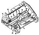
図7に、かかるヘッドを組み込んだインクジェット記録装置の一例を示す。図7において、61はワイピング部材としてのプレードであり、その一端はプレード保持部材によって保持されて固定端となり、カンチレバーの形態をなす。プレード61は記録ヘッドによる記録領域に隣接した位置に配設され、又、本例の場合、記録ヘッドの移動経路中に突出した形態で保持される。62はキャップであり、プレード61に隣接するホームポジションに配設され、記録ヘッドの移動方向と垂直な方向に移動して吐出口面と当接し、キャッピングを行う構成を備える。更に63はプレード61に隣接して設けられる吸収体であり、プレード61と同様、記録ヘッドの移動経路中に突出した形態で保持される。上記プレード61、キャップ62、吸収体63によって吐出回復部64が構成され、プレード61及び吸収体63によってインク吐出口面に水分、塵埃等の除去が行われる。
【0077】
65は吐出エネルギー発生手段を有し、吐出口を配した吐出口面に対向する布帛にインクを吐出して記録を行う記録ヘッド、66は記録ヘッド65を搭載して記録ヘッド65の移動を行う為のキャリッジである。キャリッジ66はガイド軸67と摺動可能に係合し、キャリッジ66の一部はモータ68によって駆動されるベルト69と接続(不図示)している。これによりキャリッジ66はガイド軸67に沿った移動が可能となり、記録ヘッド65による記録領域及びその隣接した領域の移動が可能となる。
【0078】
51は布帛を挿入する為の給布部、52は不図示のモータにより駆動される布送りローラである。これらの構成によって記録ヘッドの吐出口面と対向する位置へ布帛が給布され、記録が進行するにつれて排布ローラ53を配した排布部へ排布される。上記構成において記録ヘッド65が記録終了等でホームポジションに戻る際、ヘッド回復部64のキャップ62は記録ヘッド65の移動経路から退避しているが、プレード61は移動経路中に突出している。この結果、記録ヘッド65の吐出口面がワイピングされる。尚、キャップ62が記録ヘッド65の吐出面に当接してキャッピングを行う場合、キャップ62は記録ヘッドの移動経路中に突出する様に移動する。
【0079】
記録ヘッド65がホームポジションから記録開始位置へ移動する場合、キャップ62及びプレード61は上述したワイピング時の位置と同一の位置にある。この結果、この移動においても記録ヘッド65の吐出口面はワイピングされる。
【0080】
上述の記録ヘッドのホームポジションへの移動は、記録終了時や吐出回復時ばかりでなく、記録ヘッドが記録の為に記録領域を移動する間に所定の間隔で記録領域に隣接したホームポジションへ移動し、この移動に伴って上記ワイピングが行われる。図8は、ヘッドにインク供給部材、例えばチューブを介して供給されるインクを収容したインクカートリッジ45の一例を示す図である。ここで40は供給用インクを収容したインク収容部、例えば、インク袋であり、その先端にはゴム製の栓42が設けられている。この栓42に針(不図示)を挿入することにより、インク袋40中のインクをヘッドに供給可能ならしめる。44は廃インクを受容する吸収体である。インク収容部としては、インクとの接液面がポリオレフィン、特にポリエチレンで形成されているものが本発明にとって好ましい。本発明で使用されるインクジェット記録装置としては、上記の如きヘッドとインクカートリッジとが別体となったものに限らず、図9に示す如きそれらが一体になったものにも好適に用いられる。
【0081】
図9において、70は記録ユニットであって、この中にはインクを収容したインク収容部、例えば、インク吸収体が収納されており、かかるインク吸収体中のインクが複数のオリフィスを有するヘッド部71からインク滴として吐出される構成になっている。インク吸収体の材料としては、ポリウレタンを用いることが本発明にとって好ましい。72は記録ユニット内部を大気に連通させる為の大気連通口である。この記録ユニット70は、図7で示す記録ヘッドに代えて用いられるものであって、キャリッジ66に対し着脱自在になっている。
【0082】
(プリント媒体)
本実施形態に使用するプリント媒体としては、特に限定されず、例えば紙、不織布、OHP用紙、革等を用いることができる。そしてコート層として樹脂層が形成されたプリント媒体に本発明の態様の1つのインクをインクジェット法を用いて付与した場合、前述のコート層上に形成される画像の「ひび割れ」を極めて有効に防止することができることは先に述べた通りである。
【0083】
コート層として樹脂層を備えたプリント媒体の例としては、例えば紙またはポリエステル等のプラスチックフィルム上に樹脂層を設けたものが知られている。コート層を構成する材料としては、水溶性樹脂、水分散樹脂等を主成分としたもので、この他カチオン性の化合物、界面活性剤、充填剤等を適宜使用してもよい。
【0084】
水溶性樹脂としては、例えば、ポリビニルアルコール、及びアニオン変性ポリビニルアルコール、カチオン変性ポリビニルアルコール、アセタール変性ポリビニルアルコール等のポリビニルアルコールの変性物;水系ポリウレタン;ポリビニルピロリドン、及びビニルピロリドンと酢酸ビニル共重合体、ビニルピロリドンとジメチルアミノエチル・メタクリル酸の共重合体、4級化したビニルピロリドンとジメチルアミノエチル・メタクリル酸の共重合体、ビニルピロリドンとメタクリルアミドプロピル塩化トリメチルアンモニウム共重合体等のポリビニルピロリドンの変性物;カルボキシメチルセルロース、ヒドロキシエチルセルロース、ヒドロキシプロピルセルロース等のセルロース系水溶性樹脂、及びカチオン化ヒドロキシエチルセルロース等のセルロースの変性物;ポリエステル、ポリアクリル酸(エステル)、メラミン樹脂、或いはこれらの変性物、少なくともポリエステルとポリウレタンとを含むグラフト共重合体等の合成樹脂、又、アルブミン、ゼラチン、カゼイン、でんぷん、カチオン化でんぷん、アラビアゴム、アルギン酸ソーダ等の天然樹脂を挙げることができる。
又、水分散性樹脂としては、例えば、ポリ酢酸ビニル、エチレン−酢酸ビニル共重合体、ポリスチレン、スチレン−(メタ)アクリル酸エステル共重合体、(メタ)アクリル酸エステル系重合体、酢酸ビニル−(メタ)アクリル酸(エステル)共重合体、ポリ(メタ)アクリルアミド、(メタ)アクリルアミド系共重合体、スチレン−イソプレン共重合体、スチレン−ブタジエン共重合体、スチレン−プロピレン共重合体、ポリビニルエーテル、シリコン−アクリル系共重合体等、多数列挙することができるが、勿論これらに限定されるものではない。
【0085】
また、以上の他、プリント媒体のコート層の材料として、カチオン性化合物も好適に使用される。このカチオン性化合物は、分子内にカチオン性部分を含むものであれば特に限定されるものではなく、例えば、モノアルキルアンモニウムクロライド、ジアルキルアンモニウムクロライド、テトラメチルアンモニウムクロライド、トリメチルフェニルアンモニウムクロライド、エチレンオキサイド付加アンモニウムクロライド、などの4級アンモニウム塩型のカチオン性界面活性剤、あるいは、アミン塩型のカチオン性界面活性剤、さらには、カチオン性部分を含むアルキルベタイン、イミダゾリウムベタイン、アラニン系などの両性界面活性剤でもよい。また、ポリマーあるいはオリゴマーとしては、ポリアクリルアミドのカチオン変性物、あるいは、アクリルアミドとカチオン性モノマーの共重合体、ポリアリルアミン、ポリアミンスルホン、ポリビニルアミン、ポリエチレンイミン、ポリアミド−エピクロルヒドリン樹脂、ポリビニルピリジニウムハライドなどが挙げられる。
【0086】
さらに、ビニルオキサゾリドン系モノマーの単独、あるいは、他の一般的なモノマーとの共重合体、ビニルイミダゾール系モノマーの単独、あるいは、他のモノマーとの共重合体などが挙げられる。
【0087】
上記の他のモノマーとしては、メタクリレート、アクリレート、アクリロニトリル、ビニルエーテル、酢酸ビニル、エチレン、スチレンなどが挙げられる。また、カチオン変性したセルロースなどでも良い。
【0088】
以上のようなカチオン変性化合物が好適に用いられるが、もちろん、カチオン性化合物はこれらに限定されるものではない。また、コート層の厚みに関しては、乾燥重量で0.1g/m2 〜100g/m2の範囲で塗工されたものが好ましく、また、コート層を1層で構成したものの他、2層、3層構成等の多層構成で形成されたものでもよい。
【0089】
以上のようなコート層が形成されたプリント媒体は、本実施形態のインクを用いることにより、特に「ひび割れ」を防止する点で有効であることは上述の通りであるが、このような効果に加え、顔料自体、コート層に対する濡れ性が良く、これにより、コート層に対する濡れ性が劣る染料の欠点を補なうことができるという効果を得ることもできる。すなわち、本実施形態の顔料および染料の混合インクを用いることにより、色材として染料のみが含まれるインクを用いる場合に生ずるビーディングの発生を抑制することもできる。
【0090】
【実施例】
以下、上記実施形態の具体的実施例について以下に説明する。
(参考例1)図1は第1実施例に係るフルラインタイプのプリント装置の概略構成を示す側面図である。
【0091】
このプリント装置1は、プリント媒体としての記録媒体の搬送方向(同図中矢印A方向)に沿って所定位置に配置された複数のフルラインタイプのプリントヘッドよりインクを吐出してプリントを行うインクジェットプリント方式を採用するものであり、不図示の制御回路に制御されて動作する。
【0092】
ヘッド群101gの各プリントヘッド101Bk、101C、101Mおよび101Yのそれぞれは、図中A方向に搬送される記録紙の幅方向(図の紙面に垂直な方向)に約7200個のインク吐出口を配列し、最大A3サイズの記録紙に対しプリントを行うことができる。
【0093】
記録紙103は、搬送用モータにより駆動される一対のレジストローラ114の回転によってA方向に搬送され、一対のガイド板115により案内されてその先端レジ合わせが行われた後、搬送ベルト111上に搬送される。エンドレスベルトである搬送ベルト111は2個のローラ112,113により保持されている。ローラ113が回転駆動されることで、記録紙103が搬送される。なお、搬送ベルト111に対する記録紙113の吸着は静電吸着によって行われる。ローラ113は不図示のモータ等の駆動源により記録紙103を矢印A方向に搬送する方向に回転駆動される。搬送ベルト111上を搬送されこの間に記録ヘッド群101gによって記録が行われた記録紙103は、ストッカ116上へ排出される。
【0094】
記録ヘッド群101gの各プリントヘッドは、本発明の実施形態について上記で説明した第1の顔料としてブラックの顔料(自己分散型カーボンブラック)、高分子分散剤によって水性媒体中に分散させられる第2の顔料及び該高分子分散剤を含有したインクを収容したヘッド101Bk、カラーインクを各々収容した各ヘッド(シアンヘッド101C,マゼンタヘッド101M,イエローヘッド101Y)が、記録紙103の搬送方向Aに沿って図示の通りに配置されている。そして、各プリントヘッドにより各色のインクを吐出することでブラックの文字やカラー画像のプリントが可能になる。
【0095】
本実施形態では、各プリントヘッドのインク吐出口は例えば600dpiの密度で配列され、また、記録紙の搬送方向において600dpiのドット密度でプリントを行う。これにより、本実施例でプリントされる画像等のドット密度はロー方向およびカラム方向のいずれも600dpiとなる。また、各ヘッドの吐出周波数は4KHzであり、また、各プリントヘッドの吐出量は、1吐出当り15plである。
【0096】
なお、本実施例のインクジェットプリント装置にあっては、ブラックのヘッド101Bkとシアンのヘッド101Cとの間の距離Di を比較的大きくとり、これにより、プリント媒体においてBkインクがプリントされる領域とカラーインクがプリントされる領域の境界でのにじみによる混色を抑制することができる。しかしながら、コート層が形成されたプリント媒体を専用に用いる場合は、にじみ自体を抑制できるため、上記距離Di をより短かくでき、装置のサイズをより小型化されたものとすることが可能となる。
【0097】
本実施例で用いるBkインクの組成は次の通りである。なお、以下で示す各成分の量は重量部を表わし、各成分の合計は100重量部となる。
顔料分散液1:25部
顔料分散液4:25部
グリセリン:6部
ジエチレングリコール:5部
アセチレノールEH:0.1部
(川研ファインケミカル製)
水:残部
尚、上記顔料分散液1は次のようにして調製したものである。酸性カーボンブラック(商品名:MA−77(pH3.0、三菱化成社製))300gを水1000mlによく混合した後、これに次亜塩素酸ソーダ(有効塩素濃度12%)450gを滴下して、100〜105℃で10時間撹拌した。得られたスラリーを東洋濾紙No.2(アドバンティス社製)で濾過し、顔料粒子を充分に水洗した。この顔料ウェットケーキを水3000mlに再分散し、電導度0.2μsまで逆浸透膜で脱塩した。更に、この顔料分散液(pH=8〜10)を顔料濃度10重量%に濃縮した。この後、限外ろ過法を用いて以下の方法により所定範囲の粒度分布を有する分散液を得た。即ち、大小2種類の限外ろ過膜を使用し、所望の粒径より小さい粒径の顔料粒子と、所望の粒径よりも大きい粒径の顔料微粒子とを除去した。具体的には、先ず最初に顔料分散液を、分画分子量50nmの限外ろ過膜で処理することにより、50nm以下の微小粒子を除去した。次いで、分画分子量0.5μmの限外ろ過膜で同様に処理し500nm以上の粗大粒子を除去した。この方法によって、実質50nm〜500nmの粒径分布を有する顔料分散液を得た。
【0098】
以上の方法により、表面に、親水性の−COO基が直接結合したアニオン性に帯電した自己分散型カーボンブラックが分散された顔料分散液1を得た。
【0099】
以下本発明で、顔料分散液および顔料インク中の顔料粒径分布測定は、DLS−7000 (大塚電子)用いて行った。
【0100】
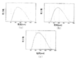
顔料分散液1から得られた粒径分布は図2(a)であり、このときの粒径極値での粒径は、130nmであった。
【0101】
また上記した顔料分散液4は次のようにして調整したものである。分散剤としてスチレン−アクリル酸−アクリル酸エチル共重合体(酸価180、平均分子量12000)14部と、モノエタノールアミン4部と水72部を混合し、ウォーターバスで70℃に加温し、樹脂分を完全に溶解させる。この際溶解させる樹脂の濃度が低いと完全に溶解しないことがあるため、樹脂を溶解する際は、高濃度溶液をあらかじめ作成しておき、希釈して希望の樹脂溶液を調整してもよい。この溶液に、分散剤の作用によって初めて水性媒体に分散可能なカーボンブラック(商品名:MCF−88、pH8.0、三菱化学製)10部を加え、以下の条件にて30分間プレミキシングを行った。次いで以下の操作を行ない、カーボンブラック(MCF−88)が分散剤によって水性媒体に分散された顔料分散体4を得た。
分散機:サイドグラインダー(五十嵐機械製)
粉砕メディア:ジルコニアビーズ1mm径
粉砕メディアの充填率:50%(体積)
粉砕時間:3時間
遠心分離処理(12000RPM、20分間)
更に得られた分散液を、顔料分散液1と同様に限外ろ過して、所定範囲の粒度分布を有する顔料分散液4を得た。この顔料分散液4から得られた粒径分布は、図2(b)であり、このときの粒径極値での粒径は、170nmであった。
【0102】
得られた顔料分散液1と顔料分散液4から得られた顔料インクから得られる粒径分布は、図2(c)でありこのときの極値は1つであった。このときの粒径極値での粒径は、145nmであった。
【0103】
上記インクを前述したインクジェットプリント装置のインクタンクに充填し、画像記録を行った。作成された画像でのドット径は大きく、画像の光学濃度も均一で高く、耐擦過性が良好で、ドットの真円性が良好であり、白すじがない良好な画像を得た。また画像品位は、記録過程を通して初期画像とほぼ同等であった。
【0104】
(実施例2)
Bkインクの他の実施例として、以下の成分のものを用いることもできる。
顔料分散液3:18部
顔料分散液4:1部
C.I.ダイレクトブルー199:1部
グリセリン:6部
ジエチレングリコール:5部
水:残部
上記顔料分散液3は、次のようにして調製した。
【0105】
水5.3gに濃塩酸5gを溶かした溶液に、5℃においてアントラニル酸1.58gを加えた。この溶液を、アイスバスで撹拌することにより常に10℃以下に保ち、5℃の水8.7gに亜硝酸ナトリウム1.78gを加えた溶液を加えた。更に、15分撹拌した後、表面積が320m2 /gでDBP吸油量が120ml/100gのカーボンブラック20gを混合した状態のまま加えた。その後、更に15分撹拌した。得られたスラリーを東洋濾紙No.2(アドバンティス社製)で濾過し、顔料分子を充分に水洗し、110℃のオーブンで乾燥させた後、この顔料に水を足して顔料濃度10重量%の顔料水溶液を作製した。さらに、得られた分散液を、実施例1と同様の限外ろ過方法をもちいて所定範囲の粒度分布を有する分散液を得た。以上の方法により、下記式で表したように、表面に、フェニル基を介して親水性基が結合したアニオン性に帯電した自己分散型カーボンブラックが分散した顔料分散液3を得た。また顔料分散液4は実施例1と同様にして調製したものである。
【0106】
【化3】
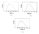
顔料分散液3から得られた粒径分布は図3(d)であり、このときの粒径極値での粒径は、120nmであった。顔料分散液4から得られた粒径分布は図3(e)であり、このときの粒径極値での粒径は、170nmであった。
【0108】
上記顔料分散液3及び4から得られた顔料インクから求められる粒径分布は、図3(f)であり、極値は1つであった。このときの粒径極値での粒径は、135nmであった。
【0109】
上記、インクを前述したインクジェットプリント装置のインクタンクに充填し、複数枚の画像記録を行った。インク吐出安定性も良好で初期と連続印字時後において作成された画像でのドット径は大きく、画像の光学濃度も均一で高く、耐擦過性が良好で,ドットの真円性が良好であり、また白すじがない良好な画像を得た。また、画像品位は、記録過程を通して初期画像とほぼ同等であった。
【0110】
(比較例1)
以上示した実施例1〜2に対する比較例として、実施例1と同様にして調製した顔料分散体4のみを用いて以下の成分のインクを作製した。
顔料分散体4:50部
エチレングリコール:8部
グリセリン:5部
イソプロピルアルコール:33部
上記、インクを前述したインクジェットプリント装置のインクタンクに充填し、複数枚の画像記録を行った。その結果、ドットの広がりが上記実施例のものと比較すると不十分であり、また周囲形状は、上記実施例によって得られたものと比較すると、線画像のエッジ部分の直線性が失われていた。また画像の光学濃度についても、実施例の画像と比較すると劣っていた。
【0111】
【発明の効果】
以上の説明から明らかなように、本発明の一態様によれば自己分散性の顔料(第1の顔料)と分散剤の作用によって初めて水性媒体に分散させることができる顔料(第2の顔料)及び該分散剤を含有したインクは、該第1の顔料自体が該第2の顔料の分散剤として機能するためか、分散剤の含有量が少なくても該第2の顔料はインク中で安定に分散しており、保存性の優れたインクを得られる。一方このインクを例えばプリントに用いた場合、記録媒体上で生じる第2の顔料と分散剤との相互作用によって生じる顔料の凝集が第1の顔料によって緩和されるためか、顔料の凝集物は細かい粒子状になってインクドット内に均一に分散し、適切な広がりを持つドット径を有し、且つドット内の画像濃度分布が均一で、またフェザリング等が殆どない、周囲や外形形状の優れたインクドットを得ることができる。更に、本態様によれば、第1の顔料と第2の顔料との相互作用に基づいていると考えられる上記の効果が、より効率的に達成される。これは、第1の顔料のサイズと第2の顔料のサイズとが近似した結果によるものと考えられる。
【0112】
更に本発明の別の態様にかかる、第1の顔料、第2の顔料、分散剤及び染料を含むインクは、染料によって顔料の凝集力がより緩和されるためか、記録媒体上では顔料の凝集物は細かい粒子状となる。一方、染料はこの粒子状の顔料の回りを取込み、全体としてプリント画像は凝集による不均一が抑制されたものとなる。そしてその効果は、このインクをインク吸収性の悪いプリント媒体に対してインクジェット記録した場合にもインクドットへの「ひび割れ」の発生を極めて有効に抑制でき、或いは防止することができる点において最も顕著に観察することができる。
【0113】
なお、本明細書中、「部」または「%」とある場合は、特に断りのない限り重量基準である。
【図面の簡単な説明】
【図1】本発明の一実施形態に係るインクジェットプリント装置の概略構成を示す側面図である。
【図2】本発明のさらに実施例1に係る顔料分散体およびインクの粒径分布を表す図である。
【図3】本発明のさらに実施例2に係る顔料分散体およびインクの粒径分布を表す図である。
【図4】インクジェット記録装置のヘッド部の縦断面図である。
【図5】インクジェット記録装置のヘッド部の横断面図である。
【図6】図4に示したヘッドをマルチ化したヘッドの外観斜視図である。
【図7】インクジェット記録装置の一例を示す斜視図である。
【図8】インクカートリッジの縦断面図である。
【図9】記録ユニットの斜視図である。
【符号の説明】
101g ヘッド群
101Bk、101C、101M、101Y プリントヘッド
103 記録紙
111 搬送ベルト
112 ローラ
113 ローラ
114 レジストローラ
115 ガイド板
116 ストッカ[0001]
BACKGROUND OF THE INVENTION
The present invention relates to an ink, particularly an ink used in ink jet printing. The present invention is applicable to all devices capable of recording on various recording media such as paper, cloth, leather, nonwoven fabric and OHP paper, for example, office equipment such as printers, copiers, facsimiles, etc., to which an ink jet recording system is applied. Is possible. The present invention also relates to an ink cartridge, a recording unit, an ink jet recording apparatus, and an ink jet recording method.
[0002]
[Prior art]
The ink jet printing system has various advantages such as low noise, low running cost, high speed printing, easy downsizing of the apparatus, and easy colorization. In printers and copiers, etc. This is a widely used method. In such a printer or the like, in general, an ink to be used is selected from the viewpoints of print characteristics such as ejection characteristics and fixability, and print quality such as bleeding of printed images, optical reflection density, and color developability.
[0003]
It is widely known that inks that are appropriately used in inkjet are roughly classified into two types, dye inks and pigment inks, depending on the color materials contained therein. Among these, the pigment ink has advantages such as excellent water resistance and light resistance as compared with the dye ink, and enables clear character quality.
[0004]
The pigment contained in the pigment ink is normally stably dispersed in the ink using a dispersant such as a polymer dispersant. Specifically, the pigment particles are adsorbed to the polymer dispersant, and mainly the electric repulsive force of the polymer dispersant is used, and the intermolecular force acting between the pigment particles that causes the aggregation of the pigment particles. It overcomes and is stably dispersed in the ink. Therefore, it is necessary to add a polymer dispersant in the ink according to the amount of the pigment.
[0005]
When such ink is printed on plain paper using an ink jet recording method, pigments aggregate due to penetration of ink solvent such as moisture into paper and evaporation into the air. At this time, as the behavior on paper, the larger the amount of the polymer dispersant, the stronger the cohesive force. Therefore, the diameter of the ink dots formed on the print medium is smaller than that of a commonly used ink-jet dye ink, and the dot shape remains close to the distorted shape when it collides with paper. Therefore, in order to obtain ink dots having a dot diameter necessary for recording that has a recording density sufficient to form an image and that does not generate white streaks, the ink ejection volume from the inkjet head is large. It is necessary to adjust to. However, this is coupled with a decrease in the permeability to the paper due to the strong cohesion of the pigment particles adsorbed by the polymer dispersant, leading to a delay in fixing the ink on the print medium or the scratch resistance of the recorded image. May be reduced.
[0006]
In order to increase the dot diameter and improve the fixability, it is also considered that the ink contains a penetrant for the purpose of improving the penetrability of the ink into the print medium. However, this method is not desirable for high-quality recorded images such as dot shape deterioration (deterioration of dot surrounding shape such as feathering), ink penetration into the back side of paper (so-called back-through), etc. May occur concurrently. In addition, since the color material penetrates into the print medium, the optical density of the ink dots is often not so high even if the dot diameter is relatively large.
[0007]
In addition, an ink using a self-dispersing pigment has been proposed. This ink has a dot diameter smaller than that of an ink containing a pigment dispersed by the above-described dispersant because the cohesive force of the pigment on paper is weak. Although it can be expanded, it is not enough.
[0008]
In this way, various factors that influence the quality of the recorded image, such as ink fixability, ink dot diameter expansion, density uniformity within the ink dots, high optical density of the ink dots themselves, etc. are satisfied at a high level, In addition, an ink and a printing method that satisfy the stability as an ink, in particular, a characteristic that can be stably ejected as an inkjet ink, are still under investigation with the aim of further improvement.
[0009]
[Problems to be solved by the invention]
In the course of research aimed at further improving the quality of inkjet recording images, the present inventors mixed a self-dispersible pigment and a pigment that can be dispersed by a polymer dispersant and a polymer dispersant. It has been found that this ink satisfies various elements required for high image quality at a very high level and is excellent in ink stability.
[0010]
That is, as an ink in a form until it is ejected from a recording head, a self-dispersing pigment (first pigment) is dispersed in a pigment (second pigment) that can be dispersed in an aqueous medium by a polymer dispersant. The dispersion state of the pigment in the ink could be stably maintained even if the amount of the polymer dispersant as a whole of the ink was reduced, because it worked as an agent. On the other hand, when printing on paper using this ink, the dot diameter is compared with the dot diameter of the ink containing the second pigment and the polymer dispersing agent for dispersing it, or the ink containing only the first pigment. In addition, it spreads uniformly on the paper, has a high optical density (OD), and is relatively fast to fix.
[0011]
The reason why such a phenomenon is observed is not clear, but is presumed to be due to the following mechanism. That is, the second pigment and the first pigment on which the polymer dispersant is adsorbed are electrically repelled in the ink, and the cohesive force of the pigment is weaker than that of at least the polymer-dispersed pigment-only ink. Yes. When such ink is printed on the paper surface, since the polymer dispersant is adsorbed to the second pigment, the color material in the ink hardly penetrates in the thickness direction of the paper. On the other hand, with respect to the paper (lateral) direction, in the case of the ink containing the second pigment and the polymer dispersant, the polymers are rapidly entangled with the penetration of the ink solvent into the paper and the reduction of moisture due to evaporation. Or,The polymer is crosslinked between the pigments, so that the pigments strongly aggregate, whereas the ink of this embodiment,The presence of the first pigment prevents or suppresses the entanglement or crosslinking of the polymer, and the strong intermolecular force between the pigments in the ink due to the repulsion between the first pigment and the polymer dispersant. As a result, the ink easily diffuses in the lateral direction of the paper surface, and although the diffusion is relaxed, it is affected by the cohesive force between the pigments, and therefore it is disordered diffusion. It is thought that there is nothing. It is considered that this appears as securing a large dot diameter and dot roundness with a small discharge amount, and adaptability when a plurality of dots are connected, that is, good smoothing property. The phenomenon on the paper surface is that the Ka value in the Bristow method of the ink is 1 ml · m-2・ Msec-1/2If it is less than that, that is, it is designed to have a relatively low permeability with respect to the print medium, it becomes particularly prominent, and this is advantageous for improving the image quality.
[0012]
The ink of this aspect is,As described above, it is good in terms of dispersion stability in the ink tank. Also, as described above, the dot characteristics are large, the OD is high, the scratch resistance is good, and the roundness of the dots is good. It has great effects such as being good.
[0013]
The inventors of the present invention focused on the excellent ability of the ink of this aspect, and further studied. As a result, the stability of the inkjet discharge performance was improved, and the quality of the recorded image was improved. It came to discover the ink composition which can be performed.
[0014]
Therefore, an object of the present invention is to provide an ink that can stably record an image having a large area factor and a high image density.
[0015]
Another object of the present invention is to provide an ink jet recording method capable of stably forming a high-quality image.
[0016]
Furthermore, another object of the present invention is to provide an ink jet recording apparatus that enables stable recording of high-quality images, and an ink cartridge and a recording unit that can be used for the ink jet recording apparatus.
[0017]
[Means for solving the problems]
An ink according to an embodiment of the present invention that can achieve the above-described object is an ink containing a first pigment and a second pigment as a coloring material in a dispersed state in an aqueous medium,
The first pigment has a self-dispersing pigment or at least one cationic group directly bonded to the surface of the first pigment by at least one anionic group directly or through another atomic group Or a self-dispersing pigment bonded to the surface of the first pigment via another atomic group,
The second pigment is a pigment that can be dispersed in the aqueous medium by a polymer dispersant;
The ink further includes at least one of a polymer dispersant having the same polarity as the group bonded to the surface of the first pigment and a nonionic polymer dispersant,
The distribution function of the ink particle size x has one extreme value, and the ink particle size at the extreme value is 50 to 300 nm.The
Including more of the first pigment than the second pigment;
The ink further includes a dye having the same polarity as the group bonded to the surface of the first pigment.It is characterized by this.
[0018]
That is, as a result of the study by the present inventors, as described above, when recording characteristics in ink jet are taken into consideration, it can be dispersed in an aqueous medium by a self-dispersing pigment (first pigment) and a polymer dispersant. By defining the particle size distribution of the pigment ink mixed with the pigment (second pigment), it was possible to further optimize the ink containing the two kinds of pigments described above for inkjet recording.
[0019]
The particle size distribution of the pigment ink as described above does not simply overlap the particle size distributions of the first pigment and the second pigment. When pigment inks having different properties are mixed, the particle size distribution is slightly different from the simple sum of the particle size distributions of the respective inks. For example, two pigments having different pigment particle size distributions If the peak of the particle size distribution is close, the particle size distribution peak of the mixed pigment ink can be one.
[0020]
The reason why the ink according to the present invention exhibits the various effects described above is not clear, but the particle diameter of the first pigment and the particle diameter of the second pigment are relatively close to each other, thereby It is considered that the interaction between the first pigment and the second pigment is more efficiently generated. In addition, the extreme value of the ink particle diameter is 50 to 300 n.mBy setting it within the range, it is considered that minute pigment particles that cause a decrease in optical density and large pigment particles that may decrease ejection stability can be substantially excluded from the ink.
[0021]
Further, as described above, the ink of this embodiment is good in terms of dispersion stability in the ink tank. Also, as described above, the dot diameter is large, the optical density of the image is high, and the scratch resistance is high. Is good and the roundness of dots is good.
[0022]
DETAILED DESCRIPTION OF THE INVENTION
Next, the present invention will be described in detail based on ink as one of the embodiments that can achieve the object of the present invention.
[0023]
As an example of the ink that can be used in the present invention, for example, an ink containing a first pigment and a second pigment dispersed in an aqueous medium as a coloring material, the first pigment being at least one anion The self-dispersing pigment or the at least one cationic group in which the ionic group is bonded to the surface of the first pigment directly or through another atomic group is directly or through the other atomic group A self-dispersing pigment bonded to the surface of one pigment, and the second pigment is a pigment that can be dispersed in the aqueous medium by a polymer dispersant or a nonionic polymer dispersant; The ink further includes at least one of a polymer dispersant having the same polarity as the group bonded to the surface of the first pigment and a nonionic polymer dispersant, and has an extreme value in the distribution function of the ink particle size x. Have one And ink particles 径極 values include ink, which is a 50 to 300 nm.
[0024]
Hereinafter, the ink will be sequentially described.
(First pigment)
Self-dispersing pigments are ink-jet recording technologies that maintain stable dispersion in water, water-soluble organic solvents, or liquids mixed with these without the use of dispersants such as water-soluble polymer compounds. It refers to a pigment that does not cause agglomerates of pigments in the liquid to interfere with normal ink ejection from the orifice used.
[0025]
(Anionic self-dispersing CB)
As such a pigment, for example, a pigment in which at least one anionic group is bonded to the pigment surface directly or via another atomic group is suitably used. Specific examples include at least one anionic group. It includes carbon black bonded to the surface directly or through other atomic groups.
[0026]
Examples of anionic groups bonded to such carbon black include, for example, —COOM, —SOThreeM, -POThreeHM, -POThreeM2(Wherein, M represents a hydrogen atom, an alkali metal, ammonium, or organic ammonium).
[0027]
Examples of the “M” alkali metal include lithium, sodium, potassium, and the like, and examples of the “M” organic ammonium include mono to trimethyl ammonium, mono to triethyl ammonium, and mono to trimethanol ammonium. It is done. Among these anionic groups, especially -COOM and -SOThreeM is preferable because it has a large effect of stabilizing the dispersion state of carbon black.
[0028]
By the way, it is preferable to use the above-mentioned various anionic groups bonded to the surface of carbon black through other atomic groups. Examples of the other atomic group include a linear or unsubstituted alkylene group having 1 to 12 carbon atoms, a substituted or unsubstituted phenylene group, or a substituted or unsubstituted naphthylene group. Here, examples of the substituent which may be bonded to the phenylene group or naphthylene group include a linear or branched alkyl group having 1 to 6 carbon atoms.
[0029]
Specific examples of the anionic group bonded to the surface of carbon black through other atomic groups include, for example, —C2HFourCOOM, -PhSOThreeExamples include M, -PhCOOM, etc. (where M is defined in the same manner as described above, and Ph represents a phenyl group), but is not limited thereto.
[0030]
Carbon black in which an anionic group is bonded to the surface directly or through another atomic group as described above can be produced, for example, by the following method. That is, as a method for introducing —COONa into the carbon black surface, for example, a method of oxidizing a commercially available carbon black with sodium hypochlorite can be mentioned. Further, for example, as a method of bonding an —Ar—COONa group (where Ar represents an aryl group) to the surface of carbon black, NH2A method of forming a diazonium salt in which nitrous acid is allowed to act on the —Ar—COONa group and bonding it to the surface of carbon black can be mentioned, but the present invention is of course not limited thereto.
[0031]
(Cationic self-dispersing CB)
(Cationically charged CB)
Examples of the cationically charged carbon black include those in which at least one selected from the following quaternary ammonium groups is bonded to the surface of carbon black.
[0032]
-N+HThree, -N+RThree, -SO2NH2, -SO2NHCOR,
[0033]
[Chemical 1]
In the above formula, R represents, for example, a linear or branched alkyl group having 1 to 12 carbon atoms, a substituted or unsubstituted phenyl group, or a substituted or unsubstituted naphthyl group. Here, examples of the substituent of the phenyl group or naphthyl group include linear or branched alkyl groups having 1 to 6 carbon atoms. Examples of the substituent when R is a phenyl group having a substituent or a naphthyl group having a substituent include, for example, C1~ C6And a linear or branched alkyl group. Examples of a method for producing a self-dispersing carbon black having a hydrophilic group bonded thereto and charged cationically include, for example, an N-ethylpyridyl group having the structure shown below:
[0035]
[Chemical 2]
As an example, a method of bonding carbon black is a method of treating carbon black with 3-amino-N-ethylpyridinium bromide. In this way, carbon black charged anionic or cationic by introducing a hydrophilic group to the surface of carbon black has excellent water dispersibility due to repulsion of ions, so even when it is contained in aqueous ink. A stable dispersion state is maintained without adding a dispersant or the like.
[0037]
By the way, various hydrophilic groups as described above may be directly bonded to the surface of carbon black. Alternatively, other atomic groups may be interposed between the carbon black surface and the hydrophilic group, and the hydrophilic group may be indirectly bonded to the carbon black surface. Here, specific examples of the other atomic groups include, for example, a linear or branched alkylene group having 1 to 12 carbon atoms, a substituted or unsubstituted phenylene group, and a substituted or unsubstituted naphthylene group. Here, examples of the substituent of the phenylene group and the naphthylene group include linear or branched alkyl groups having 1 to 6 carbon atoms. Specific examples of combinations of other atomic groups and hydrophilic groups include, for example, C2HFourCOOM, -Ph-SOThreeM, -Ph-COOM, etc. (where Ph represents a phenyl group, and M is as defined above).
[0038]
Incidentally, it is preferable that 80% or more of the self-dispersing pigment contained in the ink according to the present embodiment has a particle diameter of 50 to 300 nm, particularly 100 to 250 nm. A specific method will be described later.
[0039]
(Second pigment)
Examples of the second pigment that can be used in the ink of the present embodiment include a pigment that can be dispersed in an ink dispersion medium, specifically, an aqueous medium by the action of a polymer dispersant. That is, a pigment that can be stably dispersed in an aqueous medium for the first time as a result of the polymer dispersant adsorbing on the surface of the pigment particles is preferably used. Examples of such pigments include, for example, black pigments such as carbon black pigments such as furnace black, lamp black, acetylene black, and channel black. As specific examples of such carbon black pigments, for example, the following can be used alone or in appropriate combination.
・ Raven 7000, Ray Van 5750, Ray Van 550, Ray Van 5000ULTRA, Ray Van 3500, Ray Van 2000, Ray Van 1500, Ray Van 1250, Ray Van 1200, Ray Van 1190ULTRA-II, Ray Van 1170, Ray Van 1255 (above Colombia), Black Pearls (Black Pearls) L, Regal 400R, Regal 330R, Regal 660R, Mogul L, Monarch 700, Monak 800, Monak 880, Monak 900, Monak 1000, Monak 1100, Monak 1300, Monak 1400, Vulcan XC-72R (above made by Cabot) Color Black FW1, Color Black FW2, Color Black F W2V,
[0040]
In addition to the black pigments described above, blue pigments, red pigments, and the like can also be used.
[0041]
The amount of the color material combining the first and second pigments is 0.1 to 15% by weight, more preferably 1 to 10% by weight, based on the total amount of ink. The ratio of the first pigment to the second pigment is preferably 5/95 to 97/3, more preferably 10/90 to 95/5. More preferably, the first pigment / second pigment = 9/1 to 4/6. Another more preferable range is a range in which the first pigment is high. In the case of such a large amount of the first pigment, not only the dispersion stability as an ink, but also the stability including the ejection stability of the head, especially the reliability due to less ejection efficiency and less wetting of the ejection port surface is exhibited. Is done.
[0042]
In addition, as the behavior of the ink on the paper, since the ink spreads effectively on the surface of the paper with an ink with a small amount of the second pigment adsorbed by the polymer dispersant, a uniform thin film is formed on the surface by the polymer dispersant. It is estimated that, and the effect of this also improves the scratch resistance of the image.
[0043]
(Polymer dispersant)
The polymer dispersant for dispersing the second pigment in an aqueous medium has, for example, a function of adsorbing on the surface of the second pigment and stably dispersing the second pigment in the aqueous medium. Preferably used. Examples of such polymer dispersants include anionic polymer dispersants, cationic polymer dispersants, and nonionic polymer dispersants.
[0044]
(Anionic polymer dispersant)
Examples thereof include a polymer of a monomer as a hydrophilic group and a monomer as a hydrophobic group and a salt thereof. Specific examples of the monomer as the hydrophilic group include, for example, styrene sulfonic acid, α, β-ethylenically unsaturated carboxylic acid, α, β-ethylenically unsaturated carboxylic acid derivative, acrylic acid, acrylic acid derivative, and methacrylic acid. Methacrylic acid derivatives, maleic acid, maleic acid derivatives, itaconic acid, itaconic acid derivatives, fumaric acid and fumaric acid derivatives.
[0045]
Specific examples of the monomer as the hydrophobic component include styrene, styrene derivatives, vinyl toluene, vinyl toluene derivatives, vinyl naphthalene, vinyl naphthalene derivatives, butadiene, butadiene derivatives, isoprene, isoprene derivatives, ethylene, ethylene derivatives, propylene, Examples include propylene derivatives, alkyl esters of acrylic acid, and alkyl esters of methacrylic acid.
[0046]
Specific examples of the salt include hydrogen, alkali metal, ammonium ion, organic ammonium ion, phosphonium ion, sulfonium ion, oxonium ion, stibonium ion, stannonium, iodonium and other onium compounds. It is not limited to. In addition, the above polymers and salts thereof include polyoxyethylene group, hydroxyl group, acrylamide, acrylamide derivative, dimethylaminoethyl methacrylate, ethoxyethyl methacrylate, butoxyethyl methacrylate, ethoxytriethylene methacrylate, methoxypolyethylene glycol methacrylate, vinylpyrrolidone, vinylpyridine, Vinyl alcohol and alkyl ether may be appropriately added.
[0047]
(Cationic polymer dispersant)
As the cationic dispersant, a tertiary amine monomer, a copolymer obtained by quaternizing these with a hydrophobic monomer, or the like is used. As the tertiary amine monomer, for example, N, N-dimethylaminoethyl methacrylate, N, N-dimethylacrylamide and the like are used. As the hydrophobic monomer, styrene, a styrene derivative, vinyl naphthalene, or the like is used. In the case of a tertiary amine, sulfuric acid, acetic acid, nitric acid and the like are used as a compound for forming a salt. Further, those quaternized with methyl chloride, dimethyl sulfate or the like can also be used.
[0048]
(Nonionic polymer dispersant)
Examples of nonionic polymer dispersants include polyvinyl pyrrolidone, polypropylene glycol, vinyl pyrrolidone-vinyl acetate copolymer, and the like.
[0049]
The first pigment, the second pigment, and the polymer dispersant described above can be appropriately selected in combination, and dispersed and dissolved in an aqueous medium to obtain the ink of this embodiment. In the case of using a self-dispersing pigment in which at least one anionic group is bonded to the surface of the pigment directly or through another atomic group, an anionic polymer dispersing agent is used as the polymer dispersing agent. And at least one selected from nonionic polymer dispersants are preferable from the viewpoint of ink stability, and for the same reason, at least one cationic group is directly or other atomic group as the first pigment. In the case of using a self-dispersing pigment bonded to the surface of the pigment via a cationic dispersant or nonionic polymer dispersant as the polymer dispersant Preferably it is combined with the pigment of the first at least one selected.
[0050]
(Aqueous medium)
As an aqueous medium serving as a dispersion medium for the first and second pigments, water alone or a medium containing water and a water-soluble organic solvent is used. Examples of the water-soluble organic solvent include carbon numbers such as methyl alcohol, ethyl alcohol, n-propyl alcohol, isopropyl alcohol, n-butyl alcohol, sec-butyl alcohol, tert-butyl alcohol, isobutyl alcohol, and n-pentanol. 1-5 alkyl alcohols; amides such as dimethylformamide and dimethylacetamide; ketones or ketoalcohols such as acetone and diacetone alcohol; ethers such as tetrahydrofuran and dioxane; diethylene glycol, triethylene glycol, tetraethylene glycol, di Oxyethylene or oxypropylene copolymers such as propylene glycol, tripropylene glycol, polyethylene glycol, polypropylene glycol; Alkylene glycols in which the alkylene group contains 2 to 6 carbon atoms, such as coal, propylene glycol, trimethylene glycol, triethylene glycol, 1,2,6-hexanetriol; glycerin; ethylene glycol monomethyl (or ethyl) ether; Lower alkyl ethers such as diethylene glycol monomethyl (or ethyl) ether and triethylene glycol monomethyl (or ethyl) ether; lower polyhydric alcohols such as triethylene glycol dimethyl (or ethyl) ether and tetraethylene glycol dimethyl (or ethyl) ether Dialkyl ethers; alkanolamines such as monoethanolamine, diethanolamine, triethanolamine; sulfolane, N-methyl-2-pyrrolidone, 2-pyrrole Don, 1,3-dimethyl-2-imidazolidinone. The water-soluble organic solvents as described above can be used alone or as a mixture.
[0051]
The amount of the water-soluble organic solvent in the ink can be, for example, 0.1 to 60% by weight, preferably 1 to 30% by weight, based on the total amount of the ink.
[0052]
In the present invention, ink characteristics for improving image quality can be obtained by controlling the particle diameter of the pigment fine particles within a certain range. Specifically, a method of removing at least one of the first pigment and the second pigment by, for example, ultrafiltration to remove coarse particles and fine particles can be mentioned. Ultrafiltration uses a membrane made of materials such as polyethersulfone, polyvinylidene fluoride, etc., by holding particles larger than the molecular weight cut off of the membrane on the membrane surface and allowing small particles to permeate outside the membrane. This is a method for classifying pigment particles. As the ultrafiltration membrane, commercially available ones can be used. Specifically, for example, ultrafiltration membranes having various fractional molecular weights of Filtron series marketed by Paul, Gelman Science, etc. be able to. In this way, most of the first pigment particles and the second pigment particles (for example, 80% or more) are within the range of 50 to 500 nm, particularly 50 to 300 nm, more preferably 100 to 250 nm. By using it as a coloring material, the ink according to the present invention can be prepared.
[0053]
The ink of the present embodiment containing the various components described above pays attention to the permeability to the print medium, for example, the Ka value is 1 (ml · m-2・ Msec-1/2), It is possible to obtain image dots with extremely uniform density. Hereinafter, the penetrability of the ink into the print medium will be described.
[0054]
1m ink permeability2The ink permeation amount V (unit: milliliter / m) at time t after ink droplet ejection2= Μm) is known to be expressed by the Bristow method as shown below.
V = Vr + Ka (t−tw)1/2
(However, t> tw)
Immediately after the ink droplets are dropped on the surface of the print medium, the ink droplets are mostly absorbed by the uneven portions of the surface (the roughness portion of the surface of the print medium) and hardly penetrate into the print medium. The time in the meantime is tw (wet time), and the amount of absorption in the concavo-convex portion is Vr. When the elapsed time after the ink droplet is dropped exceeds tw, the penetration amount V increases by an amount proportional to the half power of the excess time (t-tw). Ka is a proportional coefficient of this increase, and shows a value corresponding to the penetration rate.
The Ka value was measured using a liquid dynamic permeability test apparatus S (manufactured by Toyo Seiki Seisakusho) by the Bristow method. In this experiment, PB paper of Canon Inc., the present applicant, was used as a print medium (recording paper). This PB paper is a recording paper that can be used for both copying machines and LBPs using an electrophotographic system and printing using an inkjet recording system.
[0055]
Similar results were obtained for PPC paper, which is an electrophotographic paper manufactured by Canon Inc.
[0056]
The Ka value is determined by the type of surfactant and the amount added. For example, ethylene oxide-2,4,7,9-tetramethyl-5-decyne-4,7-diol (ethylene oxide-2,4,7,9-tetramethyl-5-decyen-4,7-diol (hereinafter referred to as “ethylene oxide-2,4,7,9-tetramethyl-5-decyen-4,7-diol”) By adding a nonionic surfactant called “Acetylenol” (manufactured by Kawaken Fine Chemical Co., Ltd.), the permeability is increased.
[0057]
In addition, in the case of an ink in which acetylenol is not mixed (content ratio is 0%), the permeability is low, and the ink has properties as an overlay ink specified later. Further, when acetylenol is mixed at a content ratio of 1%, it has a property of penetrating into the recording paper in a short time and has a property as a highly penetrable ink defined later. An ink in which acetylenol is mixed at a content ratio of 0.35% has a property as a semi-permeable ink intermediate between the two.
[0058]
[Table 1]
Table 1 above shows the Ka value, the acetylenol content (%), and the surface tension (mN / m) for each of “hardly penetrating ink”, “semi-permeable ink”, and “highly penetrating ink”. Yes. The permeability of each ink to the recording paper as a print medium increases as the Ka value increases. That is, the smaller the surface tension, the higher.
[0060]
The Ka values in Table 1 were measured using the liquid dynamic permeability test apparatus S (manufactured by Toyo Seiki Seisakusho) using the Bristow method as described above. In the experiment, the aforementioned PB paper from Canon Inc. was used as the recording paper. Similar results were obtained for the above-mentioned PPC paper from Canon Inc.
[0061]
Here, the ink of the system defined as “highly penetrating ink” has an acetylenol content ratio of 0.7% or more, and is in a range in which good results regarding penetrability are obtained. Further, as a standard of permeability to be carried on the ink of this embodiment, the Ka value of “hard permeability”, that is, 1.0 (ml · m-2・ Msec-1/2), Preferably 0.4 (ml · m-2・ Msec-1/2The following are preferred.
[0062]
(Addition of dye)
A dye may be further added to the ink of the above embodiment. That is, an ink in which a dye is further added to an ink containing a dispersant for dispersing the first pigment, the second pigment, and the second pigment in an aqueous medium has a resin layer as a coating layer on the surface as a recording medium. High quality images can be formed without “cracking” between clusters of pigment agglomerates on the provided print media. Although it is not clear why "cracking" of an image on a print medium provided with a resin layer with an ink further added with a dye can be effectively prevented, when an image is formed on the print medium with an ink further added with a dye In addition, the pigment aggregates formed on the print medium are present as fine particles, the dye surrounds the surroundings, and the dye is filled in the portion where the aggregates are not present. In addition, as described above, the cohesion of the second pigment is alleviated by the presence of the first pigment. However, the addition of the dye further reduces the cohesion of the second pigment by one step, and It is considered that non-uniformity in the printed image such as “cracking” that tends to occur in a recording medium having poor absorbency compared to plain paper or the like can be effectively suppressed. Examples of the dye that can be used here include an anionic dye and a cationic dye, and it is preferable to employ a dye having the same polarity as that of the group bonded to the surface of the first pigment.
[0063]
(Anion, Cationic dye)
Known anionic dyes, direct dyes, reactive dyes and the like are suitably used as anionic dyes soluble in the aqueous medium that can be used in the present embodiment as described above. As the cationic dye, a known basic dye is preferably used. Particularly preferably, both dyes use a dye having a disazo or trisazo structure as a skeleton structure. It is also preferable to use two or more dyes having different skeleton structures. As the dye to be used, dyes such as cyan, magenta, and yellow may be used as long as the color tone is not significantly different from the black dye.
[0064]
(Addition amount of dye)
The amount of the dye added may be 5% to 60% by weight of the entire coloring material, but is less than 50% by considering the effective use of the effect of mixing the first and second pigments. It is preferable that Further, in the case of using ink that emphasizes printing characteristics on plain paper, the content is preferably 5% by weight to 30% by weight.
[0065]
In addition to the above components, the recording liquid of the present invention may contain a surfactant, an antifoaming material, a preservative, etc. in order to obtain a recording liquid having desired physical properties as required. Commercially available water-soluble dyes can also be added.
[0066]
Surfactants include anionic surfactants such as fatty acid salts, higher alcohol sulfates, liquid fatty oil sulfates, alkyl allyl sulfonates, polyoxyethylene alkyl ethers, polyoxyethylene alkyl esters, polyoxy There are nonionic surfactants such as ethylene sorbitan alkyl esters, acetylene alcohol, and acetylene glycol, and one or more of these can be appropriately selected and used. The amount used varies depending on the dispersant, but is preferably 0.01 to 5% by weight based on the total amount of the recording liquid.
[0067]
(Recording method)
The ink according to this embodiment is applied to the print medium using a known ink application unit to form an image.
[0068]
The ink application method in a preferred embodiment of the present invention is a known ink jet printing method. That is, the ink of the present invention is suitably used in a form in which printing is performed by ejecting ink from a print head onto a print medium. As a discharge method in the print head, a known method such as a piezo method can be adopted. However, in a preferred embodiment, thermal energy is applied to the ink, thereby generating bubbles in the ink and discharging the ink by the pressure of the bubbles. It is a method to do.
[0069]
The amount of ink ejected from the print head is preferably 0.014 picoliter (pl) or less per unit area. More specifically, it is preferably 70 pl or less at 360 dpi and 25 pl or less at 600 dpi. This is because when only one kind of pigment ink is used as the color material, the area factor is insufficient particularly on plain paper and the optical density is lowered. However, according to the ink of this embodiment, as described above. This is because, since the area factor can be increased, the amount of driving is not required.
[0070]
Also, an ink cartridge including an ink storage portion that stores the ink according to the above-described embodiment, an ink storage portion that stores the ink, and a unit that discharges the ink are integrated, and an ink jet printer An ink storage container such as a recording head configured to be detachable is also included in one embodiment of the present invention.
[0071]
As an example of an apparatus suitable for recording using the ink according to this aspect, thermal energy corresponding to a recording signal is applied to the ink held in the ink storage unit, and droplets are generated by the thermal energy. Apparatus. This apparatus will be described below.
[0072]
An example of a head configuration which is a main part of the apparatus is shown in FIGS. 4, 5 and 6.
[0073]
The
[0074]
The
[0075]
Now, when an electrical signal is applied to the electrodes 17-1 and 17-2, the region indicated by n of the
[0076]
FIG. 7 shows an example of an ink jet recording apparatus incorporating such a head. In FIG. 7, reference numeral 61 denotes a blade as a wiping member, one end of which is held by a blade holding member to become a fixed end, thus forming a cantilever. The blade 61 is disposed at a position adjacent to the recording area by the recording head, and in this example, is held in a form protruding in the moving path of the recording head. Reference numeral 62 denotes a cap, which is disposed at a home position adjacent to the blade 61 and has a configuration in which capping is performed by moving in a direction perpendicular to the moving direction of the recording head and coming into contact with the ejection port surface. Further, reference numeral 63 denotes an absorber provided adjacent to the blade 61 and, like the blade 61, is held in a form protruding in the moving path of the recording head. The blade 61, the cap 62, and the absorber 63 constitute a
[0077]
65 has a discharge energy generating means, and a recording head that performs recording by discharging ink onto a cloth facing the discharge port surface on which the discharge port is arranged. 66 has a recording head 65 mounted thereon and moves the recording head 65. It is a carriage for the purpose. The carriage 66 is slidably engaged with the guide shaft 67, and a part of the carriage 66 is connected to a belt 69 (not shown) driven by a motor 68. As a result, the carriage 66 can move along the guide shaft 67, and the recording area and its adjacent area can be moved by the recording head 65.
[0078]
Reference numeral 51 denotes a cloth supply portion for inserting a cloth, and reference numeral 52 denotes a cloth feed roller driven by a motor (not shown). With these configurations, the cloth is supplied to a position facing the discharge port surface of the recording head, and is discharged to a discharging portion provided with a discharging roller 53 as recording progresses. In the above configuration, when the recording head 65 returns to the home position due to the end of recording or the like, the cap 62 of the
[0079]
When the recording head 65 moves from the home position to the recording start position, the cap 62 and the blade 61 are at the same position as the above-described wiping position. As a result, the ejection port surface of the recording head 65 is wiped even during this movement.
[0080]
The above-mentioned movement of the recording head to the home position is not only at the end of recording or at the time of recovery of ejection, but also to the home position adjacent to the recording area at a predetermined interval while the recording head moves through the recording area for recording. Then, the wiping is performed with this movement. FIG. 8 is a view showing an example of an
[0081]
In FIG. 9,
[0082]
(Print media)
The print medium used in the present embodiment is not particularly limited, and for example, paper, non-woven fabric, OHP paper, leather, or the like can be used. When the ink of one aspect of the present invention is applied to a print medium having a resin layer as a coating layer by using an ink jet method, “cracking” of the image formed on the coating layer is extremely effectively prevented. What you can do is as described above.
[0083]
As an example of a print medium provided with a resin layer as a coat layer, for example, a print medium provided with a resin layer on a plastic film such as paper or polyester is known. The material constituting the coat layer is mainly composed of a water-soluble resin, a water-dispersed resin or the like, and other cationic compounds, surfactants, fillers, and the like may be used as appropriate.
[0084]
Examples of the water-soluble resin include polyvinyl alcohol and modified products of polyvinyl alcohol such as anion-modified polyvinyl alcohol, cation-modified polyvinyl alcohol, and acetal-modified polyvinyl alcohol; water-based polyurethane; polyvinyl pyrrolidone, and vinyl pyrrolidone and vinyl acetate copolymer; Modification of polyvinylpyrrolidone such as vinylpyrrolidone and dimethylaminoethyl / methacrylic acid copolymer, quaternized vinylpyrrolidone and dimethylaminoethyl / methacrylic acid copolymer, vinylpyrrolidone and methacrylamidepropyltrimethylammonium chloride copolymer Products: Cellulose water-soluble resins such as carboxymethyl cellulose, hydroxyethyl cellulose, hydroxypropyl cellulose, and cationized hydroxyethyl cell Modified products of cellulose such as cellulose; polyesters, polyacrylic acid (esters), melamine resins, or modified products thereof, synthetic resins such as graft copolymers containing at least polyester and polyurethane, albumin, gelatin, casein And natural resins such as starch, cationized starch, gum arabic, and sodium alginate.
Examples of the water dispersible resin include polyvinyl acetate, ethylene-vinyl acetate copolymer, polystyrene, styrene- (meth) acrylate copolymer, (meth) acrylate polymer, vinyl acetate- (Meth) acrylic acid (ester) copolymer, poly (meth) acrylamide, (meth) acrylamide copolymer, styrene-isoprene copolymer, styrene-butadiene copolymer, styrene-propylene copolymer, polyvinyl ether In addition, a large number of silicon-acrylic copolymers can be listed, but of course not limited thereto.
[0085]
In addition to the above, a cationic compound is also preferably used as a material for the coating layer of the print medium. The cationic compound is not particularly limited as long as it contains a cationic moiety in the molecule. For example, monoalkylammonium chloride, dialkylammonium chloride, tetramethylammonium chloride, trimethylphenylammonium chloride, ethylene oxide addition Quaternary ammonium salt type cationic surfactants such as ammonium chloride, or amine salt type cationic surfactants, and amphoteric interfaces such as alkylbetaines, imidazolium betaines and alanines containing cationic moieties It may be an activator. Examples of the polymer or oligomer include a polyacrylamide cation-modified product, a copolymer of acrylamide and a cationic monomer, polyallylamine, polyaminesulfone, polyvinylamine, polyethyleneimine, polyamide-epichlorohydrin resin, polyvinylpyridinium halide, and the like. It is done.
[0086]
Furthermore, a vinyl oxazolidone monomer alone or a copolymer with another general monomer, a vinyl imidazole monomer alone, or a copolymer with another monomer may be mentioned.
[0087]
Examples of the other monomer include methacrylate, acrylate, acrylonitrile, vinyl ether, vinyl acetate, ethylene, and styrene. Also, cation-modified cellulose may be used.
[0088]
The cation-modified compounds as described above are preferably used, but of course, the cationic compounds are not limited to these. The thickness of the coat layer is 0.1 g / m in dry weight.2 ~ 100g / m2Those coated in the above range are preferable, and the coating layer may be formed in a multilayer structure such as a two-layer structure or a three-layer structure in addition to a single-layer coating layer.
[0089]
As described above, the print medium on which the coating layer is formed as described above is particularly effective in preventing “cracking” by using the ink of the present embodiment. In addition, the pigment itself has good wettability with respect to the coating layer, whereby the defect of the dye having poor wettability with respect to the coating layer can be compensated. In other words, by using the pigment and dye mixed ink of this embodiment, it is possible to suppress the occurrence of beading that occurs when an ink containing only a dye is used as a color material.
[0090]
【Example】
Hereinafter, specific examples of the embodiment will be described below.
(Reference example 1FIG. 1 is a side view showing a schematic configuration of a full-line type printing apparatus according to the first embodiment.
[0091]
The
[0092]
Each of the print heads 101Bk, 101C, 101M, and 101Y of the
[0093]
The
[0094]
Each print head of the
[0095]
In this embodiment, the ink discharge ports of each print head are arranged with a density of 600 dpi, for example, and printing is performed with a dot density of 600 dpi in the recording paper conveyance direction. As a result, the dot density of an image or the like printed in this embodiment is 600 dpi in both the row direction and the column direction. The ejection frequency of each head is 4 KHz, and the ejection amount of each print head is 15 pl per ejection.
[0096]
In the ink jet printing apparatus of the present embodiment, the distance Di between the black head 101Bk and the cyan head 101C is relatively large, so that the Bk ink is printed on the print medium and the color. It is possible to suppress color mixing due to bleeding at the boundary of the area where ink is printed. However, when the print medium on which the coat layer is formed is used exclusively, the blur itself can be suppressed, so that the distance Di can be shortened and the size of the apparatus can be further reduced. .
[0097]
The composition of the Bk ink used in this example is as follows. In addition, the quantity of each component shown below represents a weight part, and the sum total of each component will be 100 weight part.
Pigment dispersion 1:25 parts
Pigment dispersion 4:25 parts
Glycerin: 6 parts
Diethylene glycol: 5 parts
Acetylenol EH: 0.1 part
(Made by Kawaken Fine Chemicals)
Water: remainder
The
[0098]
By the above-described method,
[0099]
Hereinafter, in the present invention, the pigment particle size distribution in the pigment dispersion and the pigment ink was measured using DLS-7000 (Otsuka Electronics).
[0100]
The particle size distribution obtained from the
[0101]
The pigment dispersion 4 described above is prepared as follows. As a dispersant, 14 parts of a styrene-acrylic acid-ethyl acrylate copolymer (acid value 180, average molecular weight 12000), 4 parts of monoethanolamine and 72 parts of water are mixed, and heated to 70 ° C. in a water bath, Dissolve the resin completely. At this time, if the concentration of the resin to be dissolved is low, the resin may not be completely dissolved. Therefore, when the resin is dissolved, a high concentration solution may be prepared in advance and diluted to prepare a desired resin solution. To this solution, 10 parts of carbon black (trade name: MCF-88, pH 8.0, manufactured by Mitsubishi Chemical) that can be dispersed in an aqueous medium for the first time by the action of a dispersant is added, and premixing is performed for 30 minutes under the following conditions. It was. Subsequently, the following operation was performed to obtain a pigment dispersion 4 in which carbon black (MCF-88) was dispersed in an aqueous medium with a dispersant.
Dispersing machine: Side grinder (Igarashi Machine)
Grinding media: Zirconia beads 1mm diameter
Filling rate of grinding media: 50% (volume)
Grinding time: 3 hours
Centrifugation (12000 RPM, 20 minutes)
Further, the obtained dispersion was subjected to ultrafiltration in the same manner as the
[0102]
The particle size distribution obtained from the pigment ink obtained from the obtained
[0103]
The ink was filled in the ink tank of the above-described inkjet printing apparatus, and image recording was performed. The resulting image had a large dot diameter, a uniform and high optical density, good scratch resistance, good dot roundness, and no white streaks. The image quality was almost the same as the initial image throughout the recording process.
[0104]
(Example 2)
As other examples of the Bk ink, the following components may be used.
Pigment dispersion 3: 18 parts
Pigment dispersion 4: 1 part
C. I. Direct Blue 199: 1 part
Glycerin: 6 parts
Diethylene glycol: 5 parts
Water: remainder
The pigment dispersion 3 was prepared as follows.
[0105]
To a solution of 5 g of concentrated hydrochloric acid dissolved in 5.3 g of water, 1.58 g of anthranilic acid was added at 5 ° C. This solution was always kept at 10 ° C. or lower by stirring with an ice bath, and a solution obtained by adding 1.78 g of sodium nitrite to 8.7 g of water at 5 ° C. was added. Furthermore, after stirring for 15 minutes, the surface area is 320 m.2 / G of carbon black with a DBP oil absorption of 120 ml / 100 g was added in a mixed state. Thereafter, the mixture was further stirred for 15 minutes. The obtained slurry was Toyo Filter Paper No. After filtering through 2 (manufactured by Advantis), the pigment molecules were sufficiently washed with water and dried in an oven at 110 ° C., water was added to the pigment to prepare a pigment aqueous solution having a pigment concentration of 10% by weight. Furthermore, the obtained dispersion was obtained by using the same ultrafiltration method as in Example 1 to obtain a dispersion having a particle size distribution in a predetermined range. By the above method, as represented by the following formula, Pigment Dispersion Liquid 3 was obtained in which an anionically charged self-dispersing carbon black having a hydrophilic group bonded via a phenyl group was dispersed on the surface. The pigment dispersion 4 was prepared in the same manner as in Example 1.
[0106]
[Chemical Formula 3]
The particle size distribution obtained from the pigment dispersion 3 is shown in FIG. 3D, and the particle size at the extreme particle size at this time was 120 nm. The particle size distribution obtained from the pigment dispersion 4 is shown in FIG. 3 (e), and the particle size at the particle size extreme value at this time was 170 nm.
[0108]
The particle size distribution obtained from the pigment inks obtained from the pigment dispersions 3 and 4 is shown in FIG. 3 (f) and has one extreme value. At this time, the particle diameter at the particle diameter extreme value was 135 nm.
[0109]
The ink was filled in the ink tank of the above-described ink jet printing apparatus, and a plurality of images were recorded. Ink ejection stability is also good, the dot diameter in the image created at the beginning and after continuous printing is large, the optical density of the image is uniform and high, the scratch resistance is good, and the roundness of the dot is good In addition, a good image without white streaks was obtained. Further, the image quality was almost the same as that of the initial image throughout the recording process.
[0110]
(Comparative Example 1)
As a comparative example for Examples 1 and 2 shown above, inks having the following components were prepared using only the pigment dispersion 4 prepared in the same manner as in Example 1.
Pigment dispersion 4: 50 parts
Ethylene glycol: 8 parts
Glycerin: 5 parts
Isopropyl alcohol: 33 parts
The ink was filled in the ink tank of the above-described ink jet printing apparatus, and a plurality of images were recorded. As a result, the spread of the dots was insufficient compared to that of the above example, and the linearity of the edge portion of the line image was lost when compared with that obtained by the above example. . Also, the optical density of the image was inferior to that of the image of the example.
[0111]
【The invention's effect】
As is apparent from the above description, according to one aspect of the present invention, a pigment (second pigment) that can be dispersed in an aqueous medium only by the action of a self-dispersing pigment (first pigment) and a dispersant. In addition, the ink containing the dispersant is stable in the ink even if the content of the dispersant is small because the first pigment itself functions as the dispersant for the second pigment. Ink can be obtained with excellent storage stability. On the other hand, when this ink is used for printing, for example, the aggregation of the pigment caused by the interaction between the second pigment and the dispersant generated on the recording medium is alleviated by the first pigment. Excellent particle size, uniform dispersion in ink dots, dot diameter with appropriate spread, uniform image density distribution within the dots, almost no feathering, etc. Ink dots can be obtained. Furthermore, according to this aspect, the above-described effect considered to be based on the interaction between the first pigment and the second pigment is achieved more efficiently. This is considered to be due to the result of the approximation of the size of the first pigment and the size of the second pigment.
[0112]
Furthermore, in the ink containing the first pigment, the second pigment, the dispersant, and the dye according to another aspect of the present invention, the aggregation force of the pigment is further relaxed by the dye, or the aggregation of the pigment on the recording medium. Things become fine particles. On the other hand, the dye takes in the surroundings of the particulate pigment, and the print image as a whole is suppressed from unevenness due to aggregation. The effect is most significant in that the occurrence of “cracking” on the ink dots can be extremely effectively suppressed or prevented even when this ink is ink-jet recorded on a print medium having poor ink absorption. Can be observed.
[0113]
In the present specification, “part” or “%” is based on weight unless otherwise specified.
[Brief description of the drawings]
FIG. 1 is a side view illustrating a schematic configuration of an inkjet printing apparatus according to an embodiment of the present invention.
FIG. 2 is a graph showing the particle size distribution of a pigment dispersion and ink according to Example 1 of the present invention.
FIG. 3 is a graph showing the particle size distribution of a pigment dispersion and ink according to Example 2 of the present invention.
FIG. 4 is a longitudinal sectional view of a head portion of the ink jet recording apparatus.
FIG. 5 is a cross-sectional view of a head portion of the ink jet recording apparatus.
6 is an external perspective view of a head in which the head shown in FIG.
FIG. 7 is a perspective view illustrating an example of an ink jet recording apparatus.
FIG. 8 is a longitudinal sectional view of an ink cartridge.
FIG. 9 is a perspective view of a recording unit.
[Explanation of symbols]
101g head group
101Bk, 101C, 101M, 101Y Print head
103 Recording paper
111 Conveyor belt
112 Laura
113 Laura
114 Registration Roller
115 Guide plate
116 Stocker
Claims (12)
該第1の顔料が少なくとも1つのアニオン性の基が直接もしくは他の原子団を介して該第1の顔料の表面に結合されている自己分散型の顔料もしくは少なくとも1つのカチオン性の基が直接もしくは他の原子団を介して該第1の顔料の表面に結合されている自己分散型の顔料であり、
該第2の顔料が高分子分散剤によって該水性媒体に分散させることのできる顔料であり、
該インクは更に該第1の顔料の表面に結合されている基と同極性の高分子分散剤及びノニオン性の高分子分散剤の少なくとも一方を含み、
該インク粒径xの分布関数において極値を一つ有し、且つ極値でのインク粒径が50〜300nmであり、
前記第1の顔料を前記第2の顔料よりも多く含み、
該インクが更に該第1の顔料の表面に結合されている基と同極性の染料を含んでいることを特徴とするインク。An ink containing a first pigment and a second pigment as a coloring material in a dispersed state in an aqueous medium,
The first pigment has a self-dispersing pigment or at least one cationic group directly bonded to the surface of the first pigment by at least one anionic group directly or through another atomic group Or a self-dispersing pigment bonded to the surface of the first pigment via another atomic group,
The second pigment is a pigment that can be dispersed in the aqueous medium by a polymer dispersant;
The ink further includes at least one of a polymer dispersant having the same polarity as the group bonded to the surface of the first pigment and a nonionic polymer dispersant,
It has one extreme value in the distribution function of the ink particle diameter x, and Ri ink particle size 50~300nm der in extremes,
Including more of the first pigment than the second pigment;
The ink further comprising a dye having the same polarity as the group bonded to the surface of the first pigment .
Priority Applications (1)
| Application Number | Priority Date | Filing Date | Title |
|---|---|---|---|
| JP2001188703A JP4996018B2 (en) | 2000-06-21 | 2001-06-21 | Ink, inkjet recording method, ink cartridge, recording unit, and inkjet recording apparatus |
Applications Claiming Priority (4)
| Application Number | Priority Date | Filing Date | Title |
|---|---|---|---|
| JP2000-187018 | 2000-06-21 | ||
| JP2000187018 | 2000-06-21 | ||
| JP2000187018 | 2000-06-21 | ||
| JP2001188703A JP4996018B2 (en) | 2000-06-21 | 2001-06-21 | Ink, inkjet recording method, ink cartridge, recording unit, and inkjet recording apparatus |
Publications (3)
| Publication Number | Publication Date |
|---|---|
| JP2002088289A JP2002088289A (en) | 2002-03-27 |
| JP2002088289A5 JP2002088289A5 (en) | 2008-08-07 |
| JP4996018B2 true JP4996018B2 (en) | 2012-08-08 |
Family
ID=26594417
Family Applications (1)
| Application Number | Title | Priority Date | Filing Date |
|---|---|---|---|
| JP2001188703A Expired - Fee Related JP4996018B2 (en) | 2000-06-21 | 2001-06-21 | Ink, inkjet recording method, ink cartridge, recording unit, and inkjet recording apparatus |
Country Status (1)
| Country | Link |
|---|---|
| JP (1) | JP4996018B2 (en) |
Families Citing this family (12)
| Publication number | Priority date | Publication date | Assignee | Title |
|---|---|---|---|---|
| CN100341960C (en) * | 2002-06-03 | 2007-10-10 | 株式会社理光 | Recording ink and manufacturing method thereof, ink cartridge, ink recorded matter, inkjet recording apparatus, and inkjet recording method |
| US7055944B2 (en) | 2002-06-03 | 2006-06-06 | Ricoh Company, Ltd. | Recording ink and manufacturing method thereof, ink cartridge, ink recorded matter, inkjet recording apparatus, and inkjet recording method |
| JP2004059913A (en) * | 2002-06-03 | 2004-02-26 | Ricoh Co Ltd | Ink for recording and its preparing method as well as ink cartridge, inked record, inkjet recording device, and inkjet recording method |
| JP4534416B2 (en) * | 2002-12-02 | 2010-09-01 | コニカミノルタホールディングス株式会社 | Actinic ray curable inkjet solventless ink and image forming method using the same |
| CN101186148B (en) * | 2002-12-27 | 2014-01-22 | 佳能株式会社 | Ink jet recording method |
| JP5211440B2 (en) * | 2006-06-15 | 2013-06-12 | 富士ゼロックス株式会社 | Emulsion ink for ink jet and method for producing the same, ink jet recording method and recorded matter |
| JP2008174736A (en) * | 2006-12-20 | 2008-07-31 | Canon Inc | Aqueous ink, ink jet recording method, ink cartridge, and ink jet recording apparatus |
| JP5369466B2 (en) * | 2008-03-25 | 2013-12-18 | コニカミノルタ株式会社 | Water-based ink for ink jet and ink jet recording method |
| JP5725396B2 (en) | 2010-04-30 | 2015-05-27 | 株式会社リコー | Inkjet recording ink, recording apparatus using the same, and recorded matter |
| CN105073913A (en) * | 2013-03-12 | 2015-11-18 | 卡博特公司 | Aqueous dispersions comprising nanocrystalline cellulose, and compositions for commercial inkjet printing |
| CN108368369B (en) * | 2015-12-18 | 2022-02-11 | 花王株式会社 | Method for producing aqueous pigment dispersion |
| JP2018065956A (en) | 2016-10-21 | 2018-04-26 | キヤノン株式会社 | Ink, ink cartridge, and image recording method |
Family Cites Families (6)
| Publication number | Priority date | Publication date | Assignee | Title |
|---|---|---|---|---|
| US6852156B2 (en) * | 2000-06-05 | 2005-02-08 | E.I. Du Pont De Nemours And Company | Self-dispersing pigment and process of making and use of same |
| JP3475249B2 (en) * | 1996-07-25 | 2003-12-08 | 株式会社リコー | Recording liquid and recording method using the same |
| JP4235329B2 (en) * | 1998-12-22 | 2009-03-11 | キヤノン株式会社 | Ink, ink container, ink set, ink jet recording apparatus and ink jet printing method |
| US6646024B2 (en) * | 1999-12-14 | 2003-11-11 | Lexmark International, Inc. | Ink compositions |
| JP2001254039A (en) * | 2000-01-06 | 2001-09-18 | Seiko Epson Corp | Ink composition capable of realizing picture image excellent in color development and fixability |
| JP3589408B2 (en) * | 2000-04-10 | 2004-11-17 | セイコーエプソン株式会社 | Coating liquid, image recording method using the same, and recorded matter |
-
2001
- 2001-06-21 JP JP2001188703A patent/JP4996018B2/en not_active Expired - Fee Related
Also Published As
| Publication number | Publication date |
|---|---|
| JP2002088289A (en) | 2002-03-27 |
Similar Documents
| Publication | Publication Date | Title |
|---|---|---|
| JP4235329B2 (en) | Ink, ink container, ink set, ink jet recording apparatus and ink jet printing method | |
| JP5121099B2 (en) | Ink jet ink and ink jet recording method | |
| US6533407B2 (en) | Ink, ink jet recording method, ink cartridge, recording unit and ink jet recording apparatus | |
| US6471757B1 (en) | Ink, ink container, ink set, ink jet printing apparatus, and ink jet printing method | |
| US6387168B1 (en) | Ink, ink container, ink set, ink-jet printing apparatus and ink-jet printing process | |
| JP4981260B2 (en) | Water-based ink, reaction liquid and water-based ink set, and image forming method | |
| JP4792767B2 (en) | Ink jet ink, ink jet ink set, ink jet ink tank, ink jet recording method, and ink jet recording apparatus | |
| JP4508703B2 (en) | Ink jet ink and ink jet recording method using the same | |
| US20150029241A1 (en) | Water-based ink, ink jet recording method, ink cartridge, recording unit, ink jet recording apparatus, and image forming method | |
| JP4428758B2 (en) | Inkjet printing apparatus and method | |
| EP1167046A1 (en) | Ink jet recording apparatus and printing method thereof | |
| JP4541596B2 (en) | Inkjet printing method | |
| JP4018241B2 (en) | Recording method | |
| JP4996018B2 (en) | Ink, inkjet recording method, ink cartridge, recording unit, and inkjet recording apparatus | |
| JP4468463B2 (en) | Inkjet printing method | |
| JP4756780B2 (en) | Inkjet printing apparatus and inkjet printing method | |
| JP4018263B2 (en) | Ink, ink container, ink set, ink jet recording apparatus and ink jet printing method | |
| JP2005205611A (en) | Ink set for inkjet, inkjet recording method, and inkjet recoding apparatus | |
| JP4475620B2 (en) | Inkjet printing method | |
| JP4500579B2 (en) | Inkjet recording method | |
| JP4235331B2 (en) | Inkjet printing method | |
| JP4817540B2 (en) | Ink set, ink jet printing method using the ink set, recording unit, ink cartridge, and ink jet printing apparatus | |
| JP7262246B2 (en) | Printed matter manufacturing method | |
| JP2006008911A (en) | Aqueous ink, inkjet recording method, ink cartridge, recording unit, inkjet recording apparatus, and image forming method | |
| JP2004352996A (en) | Method for mitigating bleed of color image |
Legal Events
| Date | Code | Title | Description |
|---|---|---|---|
| A521 | Written amendment |
Free format text: JAPANESE INTERMEDIATE CODE: A523 Effective date: 20080620 |
|
| A621 | Written request for application examination |
Free format text: JAPANESE INTERMEDIATE CODE: A621 Effective date: 20080620 |
|
| RD03 | Notification of appointment of power of attorney |
Free format text: JAPANESE INTERMEDIATE CODE: A7423 Effective date: 20080620 |
|
| A977 | Report on retrieval |
Free format text: JAPANESE INTERMEDIATE CODE: A971007 Effective date: 20110527 |
|
| A131 | Notification of reasons for refusal |
Free format text: JAPANESE INTERMEDIATE CODE: A131 Effective date: 20110601 |
|
| A521 | Written amendment |
Free format text: JAPANESE INTERMEDIATE CODE: A523 Effective date: 20110729 |
|
| TRDD | Decision of grant or rejection written | ||
| A01 | Written decision to grant a patent or to grant a registration (utility model) |
Free format text: JAPANESE INTERMEDIATE CODE: A01 Effective date: 20120508 |
|
| A01 | Written decision to grant a patent or to grant a registration (utility model) |
Free format text: JAPANESE INTERMEDIATE CODE: A01 |
|
| A61 | First payment of annual fees (during grant procedure) |
Free format text: JAPANESE INTERMEDIATE CODE: A61 Effective date: 20120511 |
|
| FPAY | Renewal fee payment (event date is renewal date of database) |
Free format text: PAYMENT UNTIL: 20150518 Year of fee payment: 3 |
|
| FPAY | Renewal fee payment (event date is renewal date of database) |
Free format text: PAYMENT UNTIL: 20150518 Year of fee payment: 3 |
|
| LAPS | Cancellation because of no payment of annual fees |