JP4992922B2 - Intake valve drive unit and intake valve device - Google Patents
Intake valve drive unit and intake valve device Download PDFInfo
- Publication number
- JP4992922B2 JP4992922B2 JP2009042358A JP2009042358A JP4992922B2 JP 4992922 B2 JP4992922 B2 JP 4992922B2 JP 2009042358 A JP2009042358 A JP 2009042358A JP 2009042358 A JP2009042358 A JP 2009042358A JP 4992922 B2 JP4992922 B2 JP 4992922B2
- Authority
- JP
- Japan
- Prior art keywords
- intake valve
- drive unit
- suction
- intake
- valve device
- Prior art date
- Legal status (The legal status is an assumption and is not a legal conclusion. Google has not performed a legal analysis and makes no representation as to the accuracy of the status listed.)
- Active
Links
Images


Classifications
-
- Y—GENERAL TAGGING OF NEW TECHNOLOGICAL DEVELOPMENTS; GENERAL TAGGING OF CROSS-SECTIONAL TECHNOLOGIES SPANNING OVER SEVERAL SECTIONS OF THE IPC; TECHNICAL SUBJECTS COVERED BY FORMER USPC CROSS-REFERENCE ART COLLECTIONS [XRACs] AND DIGESTS
- Y02—TECHNOLOGIES OR APPLICATIONS FOR MITIGATION OR ADAPTATION AGAINST CLIMATE CHANGE
- Y02T—CLIMATE CHANGE MITIGATION TECHNOLOGIES RELATED TO TRANSPORTATION
- Y02T10/00—Road transport of goods or passengers
- Y02T10/10—Internal combustion engine [ICE] based vehicles
- Y02T10/12—Improving ICE efficiencies
Description
本発明は、内燃機関(以下「エンジン」という)の吸気系に用いられる吸気用弁駆動ユニット及び、当該ユニットを用いた吸気用弁装置に関する。 The present invention relates to an intake valve drive unit used in an intake system of an internal combustion engine (hereinafter referred to as “engine”), and an intake valve device using the unit.
エンジンの吸気系に設けられる吸気用弁装置として、スロットルバルブよりも燃焼室側で吸気の流れを調整するものが知られている。このような装置を用いる目的は、燃焼室内に、タンブル流、スワール流と呼ばれる吸気の流れを作出することにある。これにより、リーンな混合気領域でも安定した燃焼が得られ、結果として、燃焼効率の向上(燃費の改善)、及び、排気成分の改善を図ることが可能となる。 As an intake valve device provided in an intake system of an engine, one that adjusts the flow of intake air on the combustion chamber side of the throttle valve is known. The purpose of using such a device is to create an intake flow called a tumble flow or swirl flow in the combustion chamber. As a result, stable combustion can be obtained even in a lean air-fuel mixture region, and as a result, it is possible to improve combustion efficiency (improve fuel efficiency) and improve exhaust components.
吸気用弁装置の構造は、吸気管内の通路面積を弁体の開閉によって変化させるものである。
ところで、このような吸気用弁装置では、吸気弁用駆動ユニットによって、弁体を制御するものがある。吸気弁用駆動ユニットはモータを備えており、このモータによって、モータの回転軸に取り付けられたウォームギヤからヘリカルギヤを介して出力ギヤが駆動される。この場合、ウォームギヤの歯面の摩擦力により、ヘリカルギヤの回転が保持されることで出力ギヤの位置が保持され、その結果、弁体の位置が保持されることになる。
The structure of the intake valve device changes the passage area in the intake pipe by opening and closing the valve body.
By the way, in such an intake valve device, there is one in which a valve body is controlled by an intake valve drive unit. The intake valve drive unit includes a motor, and an output gear is driven by the motor from a worm gear attached to a rotation shaft of the motor via a helical gear. In this case, the rotation of the helical gear is held by the frictional force of the tooth surface of the worm gear, whereby the position of the output gear is held, and as a result, the position of the valve body is held.
ところが、吸気用弁装置は車両へ搭載されるため、吸気用弁装置に生じる振動が大きくなると、モータ内部のロータが軸方向で位置を変えること等から、ウォームギヤの歯面の摩擦力が低下することがある。このような場合、ヘリカルギヤが僅かずつであるが回動してしまう虞があり、結果として、弁体の位置の保持が困難になる。また、ウォームギヤの歯面にはグリスが塗布されるのが一般的であるが、エンジンルームの温度上昇によりグリスの粘度が変化するため、この点でも、ウォームギヤの歯面の摩擦力の低下を招来する。 However, since the intake valve device is mounted on a vehicle, when the vibration generated in the intake valve device increases, the frictional force of the tooth surface of the worm gear decreases because the rotor inside the motor changes its position in the axial direction. Sometimes. In such a case, there is a possibility that the helical gear is rotated little by little, and as a result, it is difficult to maintain the position of the valve body. In addition, grease is generally applied to the tooth surface of the worm gear, but since the viscosity of the grease changes as the temperature of the engine room rises, this also causes a decrease in the frictional force on the tooth surface of the worm gear. To do.
この問題を解決するためにモータへのPWM通電を行う吸気用弁装置があるが、モータ軸に常時トルクが発生した状態となるため、ウォームギヤとヘリカルギヤとが食い込むという不具合の発生が見受けられる。また、常時の通電により、モータのブラシの摩耗が促進されたり、モータの発熱が大きくなったりするため、モータの寿命が短くなってしまう虞がある。 In order to solve this problem, there is an intake valve device that performs PWM energization to the motor. However, since torque is constantly generated in the motor shaft, there is a problem that the worm gear and the helical gear bite. In addition, the normal energization promotes the wear of the brush of the motor or increases the heat generation of the motor, which may shorten the life of the motor.
そこで、本出願人は、永久磁石を用いて弁体の位置を保持する装置を提案した(特許文献1参照)。この装置では、永久磁石の当接及び吸着により、弁体の位置が保持される。 Therefore, the present applicant has proposed a device that holds the position of the valve body using a permanent magnet (see Patent Document 1). In this apparatus, the position of the valve body is maintained by the contact and adsorption of the permanent magnet.
しかしながら、上記特許文献1に記載の技術は、永久磁石同士、あるいは、永久磁石と磁性体とを吸着させるものであるため、永久磁石又は磁性体の破損を招き易いことは否めない。結果として、吸気用弁駆動ユニットの信頼性、ひいては、吸気用弁装置の信頼性を低下させてしまうことが懸念される。
However, since the technique described in
本発明は、上述した問題点を解決するためになされたものであり、その目的は、弁体の位置を確実に保持し、しかも信頼性の高い吸気用弁駆動ユニットを提供することにある。 The present invention has been made to solve the above-described problems, and an object of the present invention is to provide a highly reliable intake valve drive unit that reliably holds the position of the valve body.
請求項1に記載の吸気用弁駆動ユニットは、エンジンの吸気管において通路面積を変化させるよう弁体を開閉駆動するものである。本ユニットでは、モータが弁体の開閉駆動を司る。モータの駆動力を伝達するのが伝達ギヤであり、伝達ギヤに噛合い、弁体の回動軸としての弁軸に取り付けられるのが、出力ギヤである。 According to a first aspect of the present invention, there is provided an intake valve drive unit for opening and closing a valve body so as to change a passage area in an intake pipe of an engine. In this unit, the motor controls the opening and closing of the valve body. The transmission gear transmits the driving force of the motor, and the output gear is engaged with the transmission gear and attached to the valve shaft as the rotation shaft of the valve body.
ここで特に本発明では、吸引部が、出力ギヤに設けられており、当該出力ギヤの回動に伴って弁軸周りに移動する。一方、被吸引部は、吸引部の移動範囲のうち所定位置に対応させて設けられる。これにより、吸引部がその所定位置に来ると、被吸引部との間に非接触状態で吸引力が作用する。 Here, particularly in the present invention, the suction portion is provided in the output gear, and moves around the valve shaft as the output gear rotates. On the other hand, the sucked part is provided corresponding to a predetermined position in the moving range of the sucking part. Thereby, when the suction part comes to the predetermined position, a suction force acts in a non-contact state with the sucked part.
このように所定位置では吸引部と被吸引部との間には吸引力が作用するため、当該吸引力が作用した状態では、弁体の位置を確実に保持することができる。また、この吸引力は非接触状態で作用するため、吸引部又は被吸引部の破損を防止することができる。その結果、吸気用弁駆動ユニットの信頼性を向上させることができる。 As described above, since a suction force acts between the suction portion and the portion to be sucked at the predetermined position, the position of the valve body can be reliably held in a state where the suction force is applied. Moreover, since this suction force acts in a non-contact state, it is possible to prevent damage to the suction part or the sucked part. As a result, the reliability of the intake valve drive unit can be improved.
吸引力が作用する所定位置は、請求項2に示すように、弁体の全開位置及び全閉位置に対応する2つの位置とすることが考えられる。このようにすれば、弁体を全開位置及び全閉位置に確実に保持することができる。 It is conceivable that the predetermined position where the suction force acts is two positions corresponding to the fully open position and the fully closed position of the valve body, as shown in claim 2. In this way, the valve body can be reliably held in the fully open position and the fully closed position.
ところで、吸引部と被吸引部との間に作用する吸引力は、請求項3に示すように、所定位置において弁軸方向に作用することとしてもよい。この場合、所定位置において吸引部と被吸引部とが弁軸方向に並んで配置される構成が例示される。また、吸引力は、請求項4に示すように、所定位置において径方向に作用することとしてもよい。この場合、所定位置において吸引部と被吸引部とが径方向に並んで配置される構成が例示される。 By the way, as shown in claim 3, the suction force acting between the suction portion and the suction target portion may act in the valve shaft direction at a predetermined position. In this case, a configuration in which the suction portion and the suction target portion are arranged side by side in the valve axis direction at a predetermined position is exemplified. Further, as shown in claim 4, the suction force may act in the radial direction at a predetermined position. In this case, the structure by which a suction part and a to-be-sucked part are arrange | positioned along with radial direction in a predetermined position is illustrated.
仮に出力ギヤの回動方向(周方向)に吸引力が作用する構成とした場合、モータによる出力ギヤの駆動に対する吸引力の影響が大きくなる虞がある。これに対し、上述した構成を採用すると、回動方向と垂直な軸方向や径方向に吸引力が作用するため、出力ギヤの駆動に対する吸引力の影響を抑制することができる。 If the suction force acts in the rotation direction (circumferential direction) of the output gear, the influence of the suction force on the drive of the output gear by the motor may increase. On the other hand, when the above-described configuration is adopted, the suction force acts in the axial direction and the radial direction perpendicular to the rotation direction, so that the influence of the suction force on the driving of the output gear can be suppressed.
ところで、吸引部及び被吸引部の少なくとも一方を永久磁石として構成することが考えられる(請求項5、7)。そして、出力ギヤ側の吸引部が永久磁石である構成においては、請求項6に示すように、吸引部の移動範囲のうちの特定位置に対応させて磁気検知手段を設けるようにしてもよい。ここで磁気検知手段は、例えばホールICとして具現化される。このようにすれば、吸引部の通過を磁気検知手段にて判断することができ、吸引部を利用して出力ギヤの回動情報を取得することができる。 By the way, it is conceivable to configure at least one of the attracting part and the attracted part as a permanent magnet (claims 5 and 7). In the configuration in which the attraction portion on the output gear side is a permanent magnet, as shown in claim 6, magnetic detection means may be provided in correspondence with a specific position in the moving range of the attraction portion. Here, the magnetic detection means is embodied as a Hall IC, for example. If it does in this way, passage of an attraction part can be judged by a magnetic detection means, and rotation information on an output gear can be acquired using an attraction part.
以上は吸気用弁駆動ユニットの発明として説明してきたが、本発明は、当該ユニットを用いて構成される吸気用弁装置の発明として実現することもできる。
すなわち、吸気用弁装置は、エンジンの吸気管において通路面積を変化させるものであって、吸気管の通路面積を変化させる弁体と、弁体を回動可能に保持する弁軸と、弁体の開閉駆動を司るモータと、モータの駆動力を伝達する伝達ギヤと、伝達ギヤに噛合い、弁軸に取り付けられる出力ギヤと、出力ギヤに設けられ、当該出力ギヤの回動に伴って弁軸周りに移動する吸引部と、吸引部がその移動範囲のうちの所定位置に来ると、非接触状態で吸引力が作用するよう当該所定位置に対応させて設けられる被吸引部と、を備えていることを特徴とする。
Although the above description has been given as an invention of an intake valve drive unit, the present invention can also be realized as an invention of an intake valve device configured using the unit.
That is, the intake valve device changes a passage area in an intake pipe of an engine, and includes a valve body that changes the passage area of the intake pipe, a valve shaft that rotatably holds the valve body, and a valve body A motor for controlling opening / closing of the motor, a transmission gear for transmitting the driving force of the motor, an output gear meshed with the transmission gear and attached to the valve shaft, and provided in the output gear. A suction portion that moves around an axis, and a suctioned portion that is provided corresponding to the predetermined position so that a suction force acts in a non-contact state when the suction portion comes to a predetermined position in the movement range. It is characterized by.
このような吸気用弁装置においても、上記吸気用弁駆動ユニットと同様の効果が奏される。すなわち、吸引部と被吸引部との間には吸引力が作用するため、弁体の位置を確実に保持することができる。また、この吸引力は非接触状態で作用するため、吸引部又は被吸引部の破損を防止することができる。その結果、吸気用弁装置の信頼性を向上させることができる。 In such an intake valve device, the same effect as the intake valve drive unit is obtained. That is, since a suction force acts between the suction part and the suctioned part, the position of the valve body can be reliably held. Moreover, since this suction force acts in a non-contact state, it is possible to prevent damage to the suction part or the sucked part. As a result, the reliability of the intake valve device can be improved.
なお、このような吸気用弁装置において、上記吸気用弁駆動ユニットと同様、請求項9〜14に示す構成を採用してもよい。これらの構成を採用すれば、上記吸気用弁駆動ユニットと同様の効果が奏される。 In such an intake valve device, the configurations shown in claims 9 to 14 may be adopted as in the intake valve drive unit. If these configurations are employed, the same effects as those of the intake valve drive unit can be obtained.
以下、本発明の実施形態を図面に基づいて説明する。本形態の吸気用弁装置は、スロットルバルブよりも下流側の吸気管の一部を構成し、吸気管の通路面積を変化させ、燃焼室内にタンブル流を作出するものである。 Hereinafter, embodiments of the present invention will be described with reference to the drawings. The intake valve device of the present embodiment constitutes a part of the intake pipe downstream of the throttle valve, changes the passage area of the intake pipe, and creates a tumble flow in the combustion chamber.
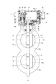
図1は、本形態の吸気用弁装置1の概略平面図である。なお、図1では、部分的に断面が現れるよう一部が切り欠かれている。図1に示すように、吸気用弁装置1は、吸気ブロック10と、吸気用弁駆動ユニット20とを備えている。
FIG. 1 is a schematic plan view of an
吸気ブロック10は、図示しないシリンダヘッドの吸気ポート上に固定される。すなわち、エンジンへの吸気管の一部を構成する。したがって、吸気ブロック10は、その内部に、吸気通路11を有する。また、吸気通路11は、仕切壁12によって仕切られている。これにより、吸気通路11は、通路面積が相対的に大きくなっているメイン通路12aと、通路面積が相対的に小さくなっているサブ通路12bとで構成されている。
The
このとき、全閉状態となることにより、メイン通路12aを閉塞するのが、弁体13である。弁体13は、板状の金属部材で形成されており、吸気通路11の中心を通る弁軸14にネジ15によって螺着されている。弁軸14は、ボールベアリング16等によって、吸気ブロック10に対し、回動可能に支持されている。これにより、弁軸14が回転駆動されることで、弁軸14を中心として弁体13が開閉する。弁体13が全開状態となるとメイン通路12a及びサブ通路12bを経由して燃焼室へ吸気が行われ、弁体13が全閉状態になるとサブ通路12bを経由して燃焼室への吸気が行われる。このように吸気用弁装置1では、エンジンの運転状態に合わせ、弁体13によって吸気通路11の通路面積を変化させることができる。
At this time, the
吸気弁用駆動ユニット20は、樹脂製のハウジング21で、その外郭を構成されている。ハウジング21の内部には、モータ22が配設されている。このモータ22の出力軸221は、図1中の左方へ延びている。したがって、モータ22の出力軸221側には、後述するような駆動力伝達部23が配置されている。一方、出力軸221とは反対側(図1中の右方)に、コネクタ24が設けられている。コネクタ24は、複数の端子241を有している。これらの端子241は、モータ22への電力供給用の端子と、後述するホールICからの信号を取得するための端子とで構成されている。
The intake
ここで上記駆動力伝達部23の構成について説明する。
駆動力伝達部23は、主として軸部25に取り付けられる各種ギヤで構成されている。軸部25が取り付けられる部分では、ハウジング21に、軸部25の一端側に対応する開口が設けられている。この開口を閉塞するのが樹脂製のカバー26であり、軸部25は、ハウジング21とカバー26とによって固定されている。
駆動力伝達部23は、ウォームギヤ231、ウォームギヤ231の背面側に設けられるヘリカルギヤ(不図示)、連結部232、伝達ギヤ233、及び出力ギヤ244を有している。
Here, the configuration of the driving
The driving
The driving
ウォームギヤ231は、モータ22の出力軸221に取り付けられる。このウォームギヤ231に対応して設けられるのが、ヘリカルギヤである。このヘリカルギヤが、上記軸部25に回動可能に支持されている。ウォームギヤ231とヘリカルギヤとの構成は周知であるため割愛するが、当該構成によって、モータ22の出力軸221から取り出される駆動力が、上記軸部25を中心とする回動力として取り出される。
The
連結部232は、円筒状の部材であり、ヘリカルギヤと伝達ギヤ233とを連結する。伝達ギヤ233は、ヘリカルギヤと同様、軸部25に回動可能に支持されている。これにより、連結部232を介し、ヘリカルギヤに連動して伝達ギヤ233が回動することになる。連結部232の軸方向の中央は、エラストマで構成されるクッションとなっている。したがって、連結部232に発生する軸方向のねじれが緩和される。
The connecting
そして、伝達ギヤ233に噛み合うのが、出力ギヤ244である。出力ギヤ244は、吸気ブロック10の弁軸14にナット27で固定されている。これにより、出力ギヤ234の回動は、弁軸14の回動となって現れる。
The output gear 244 meshes with the
次に、本形態の特徴部分である出力ギヤ234の周辺構成について説明する。
図2(a)及び(b)は、出力ギヤ234の概略平面であり、特徴的な構成のみを示す模式図である。また、図3は、図2(a)のIII−III線概略断面図であり、図4は、図2(a)のIV−IV線概略断面図である。
Next, the peripheral configuration of the
2A and 2B are schematic plane views of the
図2(a)及び(b)に示すように、出力ギヤ234は、中央部分を弁軸14(図3、図4参照)に対しナット27で固定されている。また、出力ギヤ234は、円弧に沿って歯が切られたギヤ部31、及び、径方向においてギヤ部31と反対側に設けられた吸引部32を有している。吸引部32の中央部分には、永久磁石321が埋設されている。永久磁石321は、本形態では、弁軸14の方向に磁極を有し、当該方向へ磁力線を発生させる。
As shown in FIGS. 2A and 2B, the
出力ギヤ234は、上述したようにギヤ部31に噛み合う伝達ギヤ233により、図2(a)に示す位置から図2(b)に示す位置まで、時計回りに回動可能となっている。また、図2(b)に示す位置から図2(a)に示す位置まで、反時計回りに回動可能となっている。すなわち、出力ギヤ234は、本形態では、90度の範囲を回動することになる。なお、出力ギヤ234が図2(a)の位置に来ると弁体13が全閉状態となり、また、図2(b)の位置に来ると弁体13が全開状態となるものとする。ここで吸引部32に着目すると、吸引部32は、「12時」の位置から「3時」の位置までを移動範囲とする。
The
そして、これら「12時」及び「3時」の各位置に対応させて、被吸引部41、42が設けられている。一方の被吸引部41は、図3に示すように、径内方向へ開く断面コ字状であり、吸引部32がその内部を通過可能となっている。他方の被吸引部42も同様である。また、被吸引部41、42は、磁性材料で形成されている。これにより、吸引部32が「12時」の位置に来る弁体13の全閉状態及び、吸引部32が「3時」の位置に来る弁体13の全開状態では、非接触で弁軸14方向の吸着力が作用する。
Then, suctioned
また、吸引部32の移動範囲の特定位置には、ホールIC51が配設されている。ホールIC51は、図4に示すように、センサ部511及びリード部512を樹脂にてモールされている。このホールIC51は、特定位置において、センサ部511が吸引部32に埋設された永久磁石321と弁軸14方向に並ぶように配置されている。
A
なお、本形態における弁体13が「弁体」を構成し、弁軸14が「弁軸」を構成し、モータ22が「モータ」を構成し、伝達ギヤ233が「伝達ギヤ」を構成し、出力ギヤ234が「出力ギヤ」を構成する。また、本形態における吸引部32が「吸引部」を構成し、被吸引部41、42が「被吸引部」を構成する。さらにまた、本形態におけるホールIC51が「磁気検知手段」を構成する。
In this embodiment, the
次に、本形態の吸気用弁装置1が発揮する効果を説明する。
出力ギヤ234は、上述したようにギヤ部31に噛み合う伝達ギヤ233により、図2(a)に示す位置から図2(b)に示す位置までを回動する。すなわち、出力ギヤ234は、本形態では、90度の範囲を回動することになる。ここで吸引部32に着目すると、吸引部32は、「12時」の位置から「3時」の位置までを移動範囲とする。これら各位置に対応させて、被吸引部41、42が設けられている。ここで、吸引部32には永久磁石321が埋設されており、被吸引部41、42は磁性材料で形成されている。これにより、「12時」及び「3時」の位置では、非接触で弁軸14方向の吸引力が作用する。
Next, the effect exhibited by the
The
このように「12時」及び「3時」の位置では吸引部32と被吸引部41、42との間には吸引力が作用するため、当該吸引力が作用した状態では、弁体13の位置を確実に保持することができる。また、この吸引力は非接触状態で作用するため、吸引部32又は被吸引部41、42の破損を防止することができる。その結果、吸気用弁駆動ユニット20の信頼性、ひいては、吸気用弁装置1の信頼性を向上させることができる。
In this way, at the “12 o'clock” and “3 o'clock” positions, a suction force acts between the
また、本形態では、吸引力が作用する「12時」及び「3時」の位置はそれぞれ、弁体13の全閉状態及び全開状態に対応している。これにより、弁体を全開位置及び全閉位置に確実に保持することができる。
In this embodiment, the positions of “12 o'clock” and “3 o'clock” at which the suction force acts correspond to the fully closed state and the fully open state of the
ところで、仮に出力ギヤ234の回動方向(周方向)に吸引力が作用する構成とした場合、モータ22による出力ギヤ234の駆動に対する吸引力の影響が大きくなる虞がある。この点、本形態では、永久磁石321の磁極を弁軸方向に有する構成とした。これにより、吸引部32と被吸引部41、42との間に作用する吸引力は、弁軸方向に作用する。その結果、出力ギヤ234の駆動に対する吸引力の影響を抑制することができる。
By the way, if the suction force is applied in the rotation direction (circumferential direction) of the
さらにまた、本形態では、吸引部32の移動範囲のうちの特定位置に対応させてホールIC51を設けている。これにより、吸引部32の通過をホールIC51にて判断することができ、吸引部32を利用して出力ギヤ234の回動情報を取得することができる。
Furthermore, in this embodiment, the
以上本発明は、上記形態に何等限定されるものではなく、発明の趣旨を逸脱しない範囲において種々なる形態で実施可能である。 As described above, the present invention is not limited to the above embodiment, and can be implemented in various forms without departing from the spirit of the invention.
(イ)上記形態では、出力ギヤ234は90度の範囲を回動し、弁体13の全閉状態及び全開状態が作出されていた。この点、出力ギヤの回動範囲は90度には限定されない。例えば85度の範囲を回動するようにしてもよい。また例えば95度の範囲を回動するようにしてもよい。
(A) In the above embodiment, the
(ロ)上記形態では、永久磁石321の磁極を弁軸方向に有する構成とし、吸引部32と被吸引部41、42との間に弁軸方向の吸引力が作用するようにした。これに対し、吸引部と被吸引部との間に径方向の吸引力が作用するように構成してもよい。このようにしても、出力ギヤ234の回動方向(周方向)に吸引力が作用する構成と比べ、出力ギヤ234の駆動に対する吸引力の影響を抑制することができる。
(B) In the embodiment described above, the magnetic pole of the
(ハ)上記形態では、吸引部32に永久磁石321が埋設されていた。これに対し、吸引部32と共に又は代え、被吸引部41、42を永久磁石で構成することも考えられる。
(C) In the above embodiment, the
1:吸気用弁装置、10:吸気ブロック、11:吸気通路、12:仕切壁、12a:メイン通路、12b:サブ通路、13:弁体、14:弁軸、15:ネジ、16:ボールベアリング、20:吸気用弁駆動ユニット、21:ハウジング、22:モータ、23:駆動力伝達部、24:コネクタ、25:軸部、26:カバー、27:ナット、31:ギヤ部、32:吸引部、41:被吸引部、221:出力軸、231:ウォームギヤ、232:連結部、233:伝達ギヤ、234:出力ギヤ、241:端子、244:出力ギヤ、321:永久磁石、51:ホールIC(磁気検出手段)、511:センサ部、512:リード部 1: Intake valve device, 10: Intake block, 11: Intake passage, 12: Partition wall, 12a: Main passage, 12b: Sub passage, 13: Valve body, 14: Valve shaft, 15: Screw, 16: Ball bearing , 20: intake valve drive unit, 21: housing, 22: motor, 23: driving force transmission part, 24: connector, 25: shaft part, 26: cover, 27: nut, 31: gear part, 32: suction part 41: suctioned part, 221: output shaft, 231: worm gear, 232: coupling part, 233: transmission gear, 234: output gear, 241: terminal, 244: output gear, 321: permanent magnet, 51: Hall IC ( Magnetic detection means), 511: sensor part, 512: lead part
Claims (14)
前記弁体の開閉駆動を司るモータと、
前記モータの駆動力を伝達する伝達ギヤと、
前記伝達ギヤに噛合い、前記弁体の回動軸としての弁軸に取り付けられる出力ギヤと、
前記出力ギヤに設けられ、当該出力ギヤの回動に伴って弁軸周りに移動する吸引部と、
前記吸引部がその移動範囲のうちの所定位置に来ると、非接触状態で吸引力が作用するよう当該所定位置に対応させて設けられる被吸引部と、
を備えていることを特徴とする吸気用弁駆動ユニット。 An intake valve drive unit for opening and closing a valve body so as to change a passage area in an intake pipe of an engine,
A motor for controlling opening and closing of the valve body;
A transmission gear for transmitting the driving force of the motor;
An output gear meshed with the transmission gear and attached to a valve shaft as a rotation shaft of the valve body;
A suction part provided on the output gear and moving around the valve shaft as the output gear rotates;
A suctioned portion provided corresponding to the predetermined position so that a suction force acts in a non-contact state when the suction portion comes to a predetermined position in the movement range;
An intake valve drive unit characterized by comprising:
前記所定位置は、前記弁体の全開位置及び全閉位置に対応する2つの位置であることを特徴とする吸気用弁駆動ユニット。 The intake valve drive unit according to claim 1,
The intake valve drive unit according to claim 1, wherein the predetermined positions are two positions corresponding to a fully open position and a fully closed position of the valve body.
前記吸引力は、前記所定位置において、弁軸方向に作用することを特徴とする吸気用弁駆動ユニット。 In the intake valve drive unit according to claim 1 or 2,
The intake valve drive unit according to claim 1, wherein the suction force acts in a valve shaft direction at the predetermined position.
前記吸引力は、前記所定位置において、径方向に作用することを特徴とする吸気用弁駆動ユニット。 In the intake valve drive unit according to any one of claims 1 to 3,
The intake valve drive unit, wherein the suction force acts in a radial direction at the predetermined position.
前記吸引部は、永久磁石を用いて構成されていることを特徴とする吸気用弁駆動ユニット。 In the intake valve drive unit according to any one of claims 1 to 4,
The suction valve drive unit, wherein the suction part is configured using a permanent magnet.
前記吸引部の移動範囲のうちの特定位置に対応させて配設される磁気検知手段を備えていることを特徴とする吸気用弁駆動ユニット。 In the intake valve drive unit according to claim 5,
An intake valve drive unit, comprising: a magnetic detection unit disposed in correspondence with a specific position in the moving range of the suction unit.
前記被吸引部は、永久磁石を用いて構成されていることを特徴とする吸気用弁駆動ユニット。 In the intake valve drive unit according to any one of claims 1 to 6,
The intake valve drive unit according to claim 1, wherein the sucked portion is configured using a permanent magnet.
前記吸気管の通路面積を変化させる弁体と、
前記弁体を回動可能に保持する弁軸と、
前記弁体の開閉駆動を司るモータと、
前記モータの駆動力を伝達する伝達ギヤと、
前記伝達ギヤに噛合い、前記弁軸に取り付けられる出力ギヤと、
前記出力ギヤに設けられ、当該出力ギヤの回動に伴って弁軸周りに移動する吸引部と、
前記吸引部がその移動範囲のうちの所定位置に来ると、非接触状態で弁軸方向の吸引力が作用するように当該所定位置に対応させて設けられる被吸引部と、
を備えていることを特徴とする吸気用弁装置。 An intake valve device for changing a passage area in an intake pipe of an engine,
A valve body that changes a passage area of the intake pipe;
A valve shaft that rotatably holds the valve body;
A motor for controlling opening and closing of the valve body;
A transmission gear for transmitting the driving force of the motor;
An output gear meshing with the transmission gear and attached to the valve shaft;
A suction part provided on the output gear and moving around the valve shaft as the output gear rotates;
A suctioned portion provided corresponding to the predetermined position so that a suction force in the valve shaft direction acts in a non-contact state when the suction portion comes to a predetermined position in the movement range;
An intake valve device comprising:
前記所定位置は、前記弁体の全開位置及び全閉位置に対応する2つの位置であることを特徴とする吸気用弁装置。 The intake valve device according to claim 8 ,
The intake valve device, wherein the predetermined positions are two positions corresponding to a fully open position and a fully closed position of the valve body.
前記吸引力は、前記所定位置において、弁軸方向に作用することを特徴とする吸気用弁装置。 The intake valve device according to claim 8 or 9 ,
The intake valve device, wherein the suction force acts in a valve shaft direction at the predetermined position.
前記吸引力は、前記所定位置において、径方向に作用することを特徴とする吸気用弁装置。 The intake valve device according to any one of claims 8 to 10 ,
The intake valve device, wherein the suction force acts in a radial direction at the predetermined position.
前記吸引部は、永久磁石を用いて構成されていることを特徴とする吸気用弁装置。 The intake valve device according to any one of claims 8 to 11 ,
The suction valve device is configured by using a permanent magnet.
前記吸引部の移動範囲のうちの特定位置に対応させて配設される磁気検知手段を備えていることを特徴とする吸気用弁装置。 The intake valve device according to claim 12 ,
An intake valve device comprising magnetic detection means arranged in correspondence with a specific position in the moving range of the suction portion.
前記被吸引部は、永久磁石を用いて構成されていることを特徴とする吸気用弁装置。 The intake valve device according to any one of claims 8 to 13 ,
The intake valve device, wherein the sucked part is configured using a permanent magnet.
Priority Applications (1)
| Application Number | Priority Date | Filing Date | Title |
|---|---|---|---|
| JP2009042358A JP4992922B2 (en) | 2009-02-25 | 2009-02-25 | Intake valve drive unit and intake valve device |
Applications Claiming Priority (1)
| Application Number | Priority Date | Filing Date | Title |
|---|---|---|---|
| JP2009042358A JP4992922B2 (en) | 2009-02-25 | 2009-02-25 | Intake valve drive unit and intake valve device |
Publications (3)
| Publication Number | Publication Date |
|---|---|
| JP2010196590A JP2010196590A (en) | 2010-09-09 |
| JP2010196590A5 JP2010196590A5 (en) | 2012-05-10 |
| JP4992922B2 true JP4992922B2 (en) | 2012-08-08 |
Family
ID=42821551
Family Applications (1)
| Application Number | Title | Priority Date | Filing Date |
|---|---|---|---|
| JP2009042358A Active JP4992922B2 (en) | 2009-02-25 | 2009-02-25 | Intake valve drive unit and intake valve device |
Country Status (1)
| Country | Link |
|---|---|
| JP (1) | JP4992922B2 (en) |
Families Citing this family (2)
| Publication number | Priority date | Publication date | Assignee | Title |
|---|---|---|---|---|
| KR101255550B1 (en) * | 2011-04-04 | 2013-04-17 | 주식회사 인팩 | Actuator for valve control of intake manifold |
| JP2013036414A (en) * | 2011-08-09 | 2013-02-21 | Denso Corp | Valve drive unit for intake |
Family Cites Families (6)
| Publication number | Priority date | Publication date | Assignee | Title |
|---|---|---|---|---|
| JPS6252254U (en) * | 1985-09-21 | 1987-04-01 | ||
| JP2738190B2 (en) * | 1991-12-09 | 1998-04-08 | トヨタ自動車株式会社 | Intake control device for internal combustion engine |
| JPH09329260A (en) * | 1996-06-11 | 1997-12-22 | Matsushita Electric Ind Co Ltd | Cutoff valve |
| JP4557116B2 (en) * | 2001-03-27 | 2010-10-06 | 株式会社デンソー | Valve device for intake control of internal combustion engine |
| JP2003269120A (en) * | 2002-03-14 | 2003-09-25 | Toyota Motor Corp | Solenoid operated valve |
| JP2004044605A (en) * | 2003-11-06 | 2004-02-12 | Keihin Corp | Variable intake device |
-
2009
- 2009-02-25 JP JP2009042358A patent/JP4992922B2/en active Active
Also Published As
| Publication number | Publication date |
|---|---|
| JP2010196590A (en) | 2010-09-09 |
Similar Documents
| Publication | Publication Date | Title |
|---|---|---|
| JP4285267B2 (en) | Exhaust gas recirculation device | |
| KR101150884B1 (en) | Actuator fot Vehicle | |
| JP2004150324A (en) | Electronically controlled type throttle control device | |
| JP2017067067A (en) | Torsion spring | |
| JP2007278123A (en) | Throttle valve control device | |
| JP2007236037A (en) | Motor actuator and motor driven throttle valve of internal combustion engine employing same | |
| JP2007285483A (en) | Actuator with feed screw mechanism | |
| JP4992922B2 (en) | Intake valve drive unit and intake valve device | |
| JP5138243B2 (en) | Actuator and rotating device | |
| CN111108273B (en) | Actuator device | |
| JP2004132237A (en) | Throttle control device | |
| JP5729218B2 (en) | Electronic throttle | |
| JP2004060525A (en) | Variable air suction device | |
| JPWO2007116788A1 (en) | Electric actuator | |
| JP2007068378A (en) | Motor actuator | |
| JP5003795B2 (en) | Valve drive device | |
| JP3948016B2 (en) | Throttle device | |
| JP2004132235A (en) | Throttle control device | |
| WO2021038641A1 (en) | Electronically controlled throttle device for engine | |
| JP2014009645A (en) | Engine vortex flow generating device | |
| JP2004132234A (en) | Throttle control device | |
| JP2007162902A (en) | Actuator | |
| JP2004162680A (en) | Electric type throttle body | |
| KR101677898B1 (en) | VCM Actuator Having Return Spring breakaway prevention structure | |
| JP2004270518A (en) | Electronically controlled throttle control device |
Legal Events
| Date | Code | Title | Description |
|---|---|---|---|
| A621 | Written request for application examination |
Free format text: JAPANESE INTERMEDIATE CODE: A621 Effective date: 20110314 |
|
| A977 | Report on retrieval |
Free format text: JAPANESE INTERMEDIATE CODE: A971007 Effective date: 20120315 |
|
| A521 | Request for written amendment filed |
Free format text: JAPANESE INTERMEDIATE CODE: A523 Effective date: 20120321 |
|
| TRDD | Decision of grant or rejection written | ||
| A01 | Written decision to grant a patent or to grant a registration (utility model) |
Free format text: JAPANESE INTERMEDIATE CODE: A01 Effective date: 20120410 |
|
| A01 | Written decision to grant a patent or to grant a registration (utility model) |
Free format text: JAPANESE INTERMEDIATE CODE: A01 |
|
| A61 | First payment of annual fees (during grant procedure) |
Free format text: JAPANESE INTERMEDIATE CODE: A61 Effective date: 20120423 |
|
| FPAY | Renewal fee payment (event date is renewal date of database) |
Free format text: PAYMENT UNTIL: 20150518 Year of fee payment: 3 |
|
| R151 | Written notification of patent or utility model registration |
Ref document number: 4992922 Country of ref document: JP Free format text: JAPANESE INTERMEDIATE CODE: R151 |
|
| FPAY | Renewal fee payment (event date is renewal date of database) |
Free format text: PAYMENT UNTIL: 20150518 Year of fee payment: 3 |
|
| R250 | Receipt of annual fees |
Free format text: JAPANESE INTERMEDIATE CODE: R250 |
|
| R250 | Receipt of annual fees |
Free format text: JAPANESE INTERMEDIATE CODE: R250 |
|
| R250 | Receipt of annual fees |
Free format text: JAPANESE INTERMEDIATE CODE: R250 |
|
| R250 | Receipt of annual fees |
Free format text: JAPANESE INTERMEDIATE CODE: R250 |
|
| R250 | Receipt of annual fees |
Free format text: JAPANESE INTERMEDIATE CODE: R250 |
|
| R250 | Receipt of annual fees |
Free format text: JAPANESE INTERMEDIATE CODE: R250 |
|
| R250 | Receipt of annual fees |
Free format text: JAPANESE INTERMEDIATE CODE: R250 |
|
| R250 | Receipt of annual fees |
Free format text: JAPANESE INTERMEDIATE CODE: R250 |
|
| R250 | Receipt of annual fees |
Free format text: JAPANESE INTERMEDIATE CODE: R250 |