JP4992691B2 - Rotation / linear motion combined motor position detector and rotational / linear motion combined motor - Google Patents
Rotation / linear motion combined motor position detector and rotational / linear motion combined motor Download PDFInfo
- Publication number
- JP4992691B2 JP4992691B2 JP2007315875A JP2007315875A JP4992691B2 JP 4992691 B2 JP4992691 B2 JP 4992691B2 JP 2007315875 A JP2007315875 A JP 2007315875A JP 2007315875 A JP2007315875 A JP 2007315875A JP 4992691 B2 JP4992691 B2 JP 4992691B2
- Authority
- JP
- Japan
- Prior art keywords
- hall element
- linear motion
- output voltage
- rotation
- position detection
- Prior art date
- Legal status (The legal status is an assumption and is not a legal conclusion. Google has not performed a legal analysis and makes no representation as to the accuracy of the status listed.)
- Expired - Fee Related
Links
Images


Description
本発明は、回転・直動複合型モータの出力軸の位置を検出する回転・直動複合型モータの位置検出装置および回転・直動複合型モータに関する。 The present invention relates to a position detection device for a combined rotation / linear motion motor that detects the position of an output shaft of the combined rotation / linear motion motor, and a combined rotation / linear motion motor.
従来、回転・直動複合型モータの出力軸の回転と直動の位置をそれぞれ別の位置検出装置用いて検出する回転・直動複合型モータが開示されている(例えば、特許文献1参照)。
図7は従来の回転・直動複合型モータの回転用の位置検出装置の構造を示す側断面図、図8は直動用の位置検出装置の構造を示す側断面図である。
2. Description of the Related Art Conventionally, a rotation / linear motion combined motor that detects the rotation and linear motion positions of an output shaft of a rotation / linear motion combined motor using separate position detection devices has been disclosed (for example, see Patent Document 1). .
FIG. 7 is a side sectional view showing a structure of a position detecting device for rotation of a conventional combined rotary / linear motion motor, and FIG. 8 is a side sectional view showing a structure of a position detecting device for linear motion.
先ず、回転用の位置検出装置の構造について説明する。
図7において、1はモータ部、21は回転用の位置検出装置である。
モータ部1において、16は回転・直動軸受で、出力軸9は回転方向および直動方向に移動できるように支持されている。
First, the structure of the position detection device for rotation will be described.
In FIG. 7, 1 is a motor unit, and 21 is a position detection device for rotation.
In the
回転用の位置検出装置21において、3は直動軸受、4は回転軸受である。直動軸受3はボールスプライン軸受構造となっており、インナーレース側は出力軸9に固定され、アウターレース側は回転軸受4に回転自在に取り付け支持されている。5は直動軸受3のアウターレース側に固定された回転信号発生部で、回転信号発生部5は直動軸受3に同期回転して出力軸9の回転信号を発生する。6は回転信号検出器で、回転信号検出器6は、回転信号発生部5からの信号を定位置で受けて出力軸9の回転位置を検出する。
In the position detection device 21 for rotation, 3 is a linear motion bearing and 4 is a rotation bearing. The linear motion bearing 3 has a ball spline bearing structure, the inner race side being fixed to the
次に、直動用の位置検出装置の構造について説明する。
図8において、22は直動用の位置検出装置である。
直動用の位置検出装置22において、7は直動信号発生部で、出力軸9の直動方向に対してのみ直動軸受3と同期して移動することにより、出力軸9の直動信号を発生する。直動軸受3が回転軸受4を介してモータの出力軸9の下端部を支持している。8は直動信号検出器で、直動信号発生部7からの信号を定位置で受けて、出力軸9の直動位置を検出する。
Next, the structure of the position detecting device for linear motion will be described.
In FIG. 8, 22 is a position detector for linear motion.
In the position detector 22 for linear motion, 7 is a linear motion signal generator, which moves in synchronism with the linear motion bearing 3 only in the linear motion direction of the
このように、従来の回転・直動複合型モータは、出力軸の回転位置と直動位置をそれぞれ別の装置用いて検出していた。
しかしながら、従来の回転・直動複合型モータの位置検出装置は、回転と直動の位置検出装置を別々に備え、これらを組み合わせてできているので、小型化することが困難であるという問題があった。本発明はこのような問題点に鑑みてなされたものであり、小型の、直動・複合型モータの位置検出装置を実現することを目的とする。 However, the conventional rotary / linear motion type motor position detection device is provided with separate rotation and linear motion position detection devices, which are combined to form a problem that it is difficult to reduce the size. there were. The present invention has been made in view of such problems, and an object of the present invention is to realize a small-sized linear motion / composite motor position detection device.
上記問題を解決するため、本発明は、次のように構成したものである。
すなわち、本発明の一の観点による回転・直動複合型モータの位置検出装置は、回転方向および直動方向に移動する出力軸を有するモータ部と、前記出力軸の回転位置および直動位置を検出する位置検出装置とで構成される回転・直動複合型モータの位置検出装置において、前記位置検出装置は、円板状で円板状の平面に対して水平方向に一方向に磁化され、隣り合う磁化方向が互いに反転するよう直動方向に前記平面を垂直にして等間隔に配置された複数個の位置検出用磁石を備えたことを特徴としている。
また、上記一の観点による回転・直動複合型モータの位置検出装置は、前記位置検出装置は、前記位置検出用磁石の周方向の側面に対して空隙を介して配置された第一のホール素子と、前記第一のホール素子の位置から周方向に90度だけ回転した位置に配置された第二のホール素子と、前記第一のホール素子の位置から直動方向に前記位置検出用磁石の磁極ピッチの1/2ピッチだけ離した位置に配置された第三のホール素子とを備え、前記第一のホール素子と前記第二のホール素子の出力電圧から前記回転位置を求め、前記第一のホール素子と前記第三のホール素子の出力電圧から前記直動位置を求めることを特徴としてもよい。
また、上記一の観点による回転・直動複合型モータの位置検出装置は、前記回転位置を前記第一のホール素子と前記第二のホール素子の出力電圧の逆正接演算によって求め、前記直動位置を前記第一のホール素子と前記第三のホール素子の出力電圧の逆正接演算によって求めることを特徴としてもよい。
また、上記一の観点による回転・直動複合型モータの位置検出装置は、前記位置検出装置は、前記位置検出用磁石の周方向の側面に対して空隙を介して配置された第一のホール素子と、前記第一のホール素子の位置から周方向に90度だけ回転した位置に配置された第二のホール素子と、前記第一のホール素子の位置から直動方向に前記位置検出用磁石の磁極ピッチの1/2ピッチだけ離した位置に配置された第三のホール素子と、前記第二のホール素子の位置から直動方向に前記位置検出用磁石の磁極ピッチの1/2ピッチだけ離した位置に配置された第四のホール素子とを備え、前記第一のホール素子と前記第二のホール素子の出力電圧、もしくは前記第三のホール素子と前記第四のホール素子の出力電圧から前記回転位置を求め、前記第一のホール素子と前記第三のホール素子の出力電圧、もしくは前記第二のホール素子と前記第四のホール素子の出力電圧から前記直動位置を求めることを特徴としてもよい。
また、上記一の観点による回転・直動複合型モータの位置検出装置は、前記第一のホール素子と前記第二のホール素子の出力電圧の逆正接演算、もしくは前記第三のホール素子と前記第四のホール素子の出力電圧の逆正接演算によって求め、前記直動位置を前記第一のホール素子と前記第三のホール素子の出力電圧の逆正接演算、もしくは前記第二のホール素子と前記第四のホール素子の出力電圧の逆正接演算によって求めることを特徴としてもよい。
また、本発明の他の観点による回転・直動複合型モータは、上記一の観点による回転・直動複合型モータの位置検出装置を備えたことを特徴とする特徴としている。
In order to solve the above problems, the present invention is configured as follows.
That is, a position detection device for a combined rotary / linear motion motor according to an aspect of the present invention includes a motor unit having an output shaft that moves in the rotational direction and the linear motion direction, and the rotational position and linear motion position of the output shaft. In the position detection device of the rotary / linear motion combined motor configured with the position detection device to detect, the position detection device is disc-shaped and magnetized in one direction horizontally with respect to the disc-shaped plane, A plurality of position detecting magnets arranged at equal intervals with the plane perpendicular to the linear motion direction so that adjacent magnetization directions are reversed from each other are provided.
The position detection device for a combined rotary / linear motion motor according to the first aspect is characterized in that the position detection device is a first hole disposed with a gap with respect to a circumferential side surface of the position detection magnet. An element, a second hall element disposed at a position rotated by 90 degrees in the circumferential direction from the position of the first hall element, and the position detecting magnet in the linear motion direction from the position of the first hall element A third Hall element disposed at a position separated by a half pitch of the magnetic pole pitch of the first Hall element, and determining the rotational position from the output voltage of the first Hall element and the second Hall element, The linear motion position may be obtained from output voltages of one hall element and the third hall element .
Further, the position detection device of the combined rotary / direct motion type motor according to the above one aspect obtains the rotational position by calculating an arctangent of output voltages of the first hall element and the second hall element, and the linear motion The position may be obtained by calculating an arctangent of output voltages of the first Hall element and the third Hall element .
The position detection device for a combined rotary / linear motion motor according to the first aspect is characterized in that the position detection device is a first hole disposed with a gap with respect to a circumferential side surface of the position detection magnet. An element, a second hall element disposed at a position rotated by 90 degrees in the circumferential direction from the position of the first hall element, and the position detecting magnet in the linear motion direction from the position of the first hall element A third Hall element disposed at a position separated from the magnetic pole pitch by ½ pitch, and a ½ pitch of the magnetic pole pitch of the position detecting magnet in the linear motion direction from the position of the second Hall element. A fourth Hall element disposed at a separated position, the output voltage of the first Hall element and the second Hall element, or the output voltage of the third Hall element and the fourth Hall element To determine the rotational position from Wherein the one Hall element output voltage of the third Hall element, or may also be characterized by determining the linear motion position from the output voltage of the said and second Hall elements fourth hall elements.
In addition, the position detection device of the rotary / linear motion combined motor according to the one aspect described above is an arctangent calculation of output voltages of the first Hall element and the second Hall element, or the third Hall element and the Obtained by the arc tangent calculation of the output voltage of the fourth Hall element, the linear motion position arc tangent calculation of the output voltage of the first Hall element and the third Hall element, or the second Hall element and the The fourth Hall element may be obtained by calculating an arctangent of the output voltage of the fourth Hall element .
According to another aspect of the present invention, there is provided a combined rotary / direct acting motor, comprising the position detecting device for the combined rotary / direct acting motor according to the first aspect.
本発明の一の観点による回転・直動複合型モータの位置検出装置によると、位置検出装置が、円板状で円板状の平面に対して水平方向に一方向に磁化され、隣り合う磁化方向が互いに反転するよう直動方向に円板状の平面を垂直にして等間隔に配置された複数個の位置検出用磁石を備えているので、出力軸の回転および直動の両方の位置検出ができ、位置検出装置を小型化することができる。
According to the position detection device for a combined rotary / linear motion motor according to one aspect of the present invention , the position detection device is magnetized in one direction in a horizontal direction with respect to a disk-shaped plane, and adjacent magnetizations. Since it has a plurality of position detection magnets arranged at equal intervals with the disk-shaped plane perpendicular to the linear motion direction so that the directions are reversed, both the rotational and linear motion position detection of the output shaft Thus, the position detection device can be reduced in size.
また、上記一の観点による回転・直動複合型モータの位置検出装置によると、出力軸の回転および直動の両方の位置検出を位置検出用磁石と4個のホール素子のみで行なえば、位置検出装置を小型化することができるとともに、任意の回転位置・直動位置の検出精度を向上することができる。
Further , according to the position detection device for the combined rotation / linear motion motor according to the above one aspect, if the position detection of both the rotation and the linear motion of the output shaft is performed only by the position detection magnet and the four Hall elements, The detection apparatus can be reduced in size, and the detection accuracy of an arbitrary rotational position / linear motion position can be improved.
また、本発明の他の観点による回転・直動複合型モータによると、小型の位置検出装置を備えた回転・直動複合型モータが得られる。
In addition, according to the combined rotation / linear motion motor according to another aspect of the present invention, a combined rotation / linear motion motor including a small position detection device can be obtained.
以下、本発明の実施の形態について図を参照して説明する。 Hereinafter, embodiments of the present invention will be described with reference to the drawings.
図1は、本発明の第1実施例を示す回転・直動複合型モータの側断面図である。
図1において、回転・直動複合型モータはモータ部1と位置検出装置2から構成される。モータ部1では、出力軸9が回転方向および直動方向に移動できるように、回転・直動軸受16に支持されている。位置検出装置2は出力軸9の回転と直動の絶対位置を検出する。
FIG. 1 is a cross-sectional side view of a combined rotary / linear motion motor showing a first embodiment of the present invention.
In FIG. 1, the combined rotary / linear motor includes a
位置検出装置2は、複数個の位置検出用磁石と3個のホール素子から構成される。
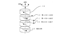
図2は図1のA−A線断面図であり、図3は図1の位置検出装置部分の側断面図である。また、図4は本実施例における位置検出装置の位置検出用磁石と3個のホール素子の配置を概略的に示した斜視図である。ただし、出力軸9は省略している。
図2において、10は位置検出用磁石で、円板形状をしており、円板の平面に対して水平方向に一方向に磁化されている。
また、図3において、複数個の円板状の永久磁石は、直動方向に対して隣接する永久磁石の間隔に等しい磁極ピッチ19が構成されるよう、円板状の平面を直動方向に対して垂直にして等間隔に配置し、さらに、磁化方向15が交互に反転するように配置した。
The
2 is a cross-sectional view taken along the line AA of FIG. 1, and FIG. 3 is a side cross-sectional view of the position detection device portion of FIG. FIG. 4 is a perspective view schematically showing the arrangement of position detection magnets and three Hall elements of the position detection apparatus in the present embodiment. However, the
In FIG. 2,
Further, in FIG. 3, the plurality of disk-shaped permanent magnets have their disk-shaped planes in the linear motion direction so that a magnetic pole pitch 19 equal to the interval between the permanent magnets adjacent to the linear motion direction is formed. The magnets were arranged so as to be perpendicular to each other at equal intervals, and further arranged so that the
図2と図3において、11は第一のホール素子、12は第二のホール素子、13は第三のホール素子である。第一のホール素子11を位置検出用磁石10の周方向の側面に対して空隙を介して配置し、第一のホール素子11の位置から周方向に90度だけ回転した位置に第二のホール素子12を配置し、第一のホール素子11の位置から直動方向に位置検出用磁石10の磁極ピッチ19の1/2ピッチ20だけ離した位置に第三のホール素子13を配置した。
2 and 3, 11 is a first Hall element, 12 is a second Hall element, and 13 is a third Hall element. The first hall element 11 is arranged with a gap with respect to the side surface in the circumferential direction of the
次に、出力軸9の回転位置および直動位置を検出する原理について説明する。
定位置に固定された第一のホール素子11は、位置検出用磁石10から発生する磁界をホール素子の感受面に対して垂直な向きの成分として検出する。ここで、出力軸9の直動位置zを固定し、回転位置θを変動させると、ホール素子が検出する磁界の大きさは回転位置θの大きさに応じて正弦波状に変化し、同時にホール素子の出力電圧V1も回転位置θに関して正弦波となる。また、回転位置θを固定し、直動位置zを変動させると、第一のホール素子11の出力電圧V1は直動位置zに関して正弦波となる。
Next, the principle of detecting the rotational position and linear motion position of the
The first Hall element 11 fixed at a fixed position detects the magnetic field generated from the
したがって、出力軸9の回転位置θと直動位置zに対する第一のホール素子11の出力電圧V1は図5に示すグラフのようになり、数式で表すと以下のようになる。
V1=sinθ・sinz (1)
ここで、出力軸9の直動位置zは、位置検出用磁石10の磁極ピッチ19を角度180度に対応させた電気角で表現しており、ホール素子の出力電圧の振幅は1[V]と設定した。
図2では、17が回転位置θの原点であり、第一ホール素子11に対する出力軸9の回転位置θが90度の場合を示している。また、図3では、18が直動位置zの原点であり、第一ホール素子11に対する出力軸9の直動位置zが90度の場合を示している。
Therefore, the output voltage V1 of the first Hall element 11 with respect to the rotational position θ and the linear movement position z of the
V1 = sin θ · sinz (1)
Here, the linear motion position z of the
FIG. 2 shows a case where 17 is the origin of the rotational position θ and the rotational position θ of the
次に、第二のホール素子12の出力電圧V2および第三のホール素子13の出力電圧V3について説明する。
図1において出力軸9を上から見たとき右回転方向を正方向の回転方向とし、出力軸9が下から上に移動する方向を正方向の直動方向とすると第二のホール素子12の出力電圧V2は、回転位置θについてV1よりもπ/2だけ位相が進んでおり、第三のホール素子13の出力電圧V3は直動位置zについて、V1よりもπ/2だけ位相が進んでいるので、V2およびV3はそれぞれ以下に示す(2)式および(3)式で表される。
V2=sin(θ+π/2)・sinz=cosθ・sinz (2)
V3=sinθ・sin(z+π/2)=sinθ・cosz (3)
Next, the output voltage V2 of the second Hall element 12 and the output voltage V3 of the third Hall element 13 will be described.
In FIG. 1, when the
V2 = sin (θ + π / 2) · sinz = cos θ · sinz (2)
V3 = sin θ · sin (z + π / 2) = sin θ · cosz (3)
従って、出力軸9の回転位置θは第一、第二のホール素子の出力電圧V1とV2を用いて、
θ=tan−1(V1/V2) [rad] (4)
で計算することができ、
出力軸9の直動位置zは第一、第三のホール素子の出力電圧V1とV3を用いて、
z=tan−1(V1/V3) [rad] (5)
で計算することができる。
Therefore, the rotational position θ of the
θ = tan −1 (V1 / V2) [rad] (4)
Can be calculated with
The linear movement position z of the
z = tan −1 (V1 / V3) [rad] (5)
Can be calculated with
(5)式では、出力軸9の直動位置zを電気角で表現しているので、距離で表現した直動位置z’は、
z’=z・L/π [m] (6)
で表すことができる。ここで、Lは位置検出用磁石の磁極ピッチ[m]を表す。
In the equation (5), the linear motion position z of the
z ′ = z · L / π [m] (6)
Can be expressed as Here, L represents the magnetic pole pitch [m] of the position detection magnet.
以上に示したように、本発明では、位置検出用磁石10とホール素子3個を用いて、出力軸9の回転位置と直動位置の検出を同時に行えるようにしたので、位置検出装置を小型化することができる。
As described above, in the present invention, the
図6は、本発明の第2実施例を示す回転・直動複合型モータの位置検出装置における、位置検出用磁石とホール素子の配置を表す斜視図である。
図6において、14は第四のホール素子である。本実施例が実施例1と異なるのは、第二のホール素子12の位置から位置検出用磁石10の磁極ピッチ19の1/2の距離20だけ軸方向に離した位置に、第四のホール素子14を追加した点である。
FIG. 6 is a perspective view showing the arrangement of position detection magnets and Hall elements in a position detection apparatus for a combined rotary and linear motor, showing a second embodiment of the present invention.
In FIG. 6, reference numeral 14 denotes a fourth Hall element. The present embodiment is different from the first embodiment in that the fourth hole is located at a position separated from the position of the second Hall element 12 in the axial direction by a distance 20 that is 1/2 of the magnetic pole pitch 19 of the
実施例1の場合と同様な計算により、第四のホール素子14の出力電圧V4は以下に示す(7)式で表される。
V4=sin(θ+π/2)・sin(z+π/2)=cosθ・cosz (7)
なお、第一〜第三のホール素子の出力電圧V1〜V3は、実施例1に記載した(1)〜(3)式でそれぞれ表される。
By the same calculation as in the first embodiment, the output voltage V4 of the fourth Hall element 14 is expressed by the following equation (7).
V4 = sin (θ + π / 2) · sin (z + π / 2) = cos θ · cosz (7)
The output voltages V1 to V3 of the first to third Hall elements are respectively expressed by the formulas (1) to (3) described in the first embodiment.
はじめに、出力軸9の回転位置θを検出する原理について説明する。位置検出用磁石10が回転したとき、第一のホール素子11の出力電圧V1と第三のホール素子13の出力電圧V3の大きさを比較して、第一のホール素子11の出力電圧V1の方が大きいときは、第一のホール素子11の出力電圧V1と第二のホール素子12の出力電圧V2を用いて出力軸9の回転位置θの計算を行い、第三のホール素子13の出力電圧V3の方が大きいときは、第三のホール素子13の出力電圧V3と第四のホール素子14の出力電圧V4を用いて出力軸の回転位置θの計算を行う。
First, the principle of detecting the rotational position θ of the
すなわち、以下の(8)又は(9)式を用いて計算する。
θ=tan−1(V1/V2) (V1>V3のとき) (8)
θ=tan−1(V3/V4) (V1≦V3のとき) (9)
That is, it calculates using the following (8) or (9) Formula.
θ = tan −1 (V1 / V2) (when V1> V3) (8)
θ = tan −1 (V3 / V4) (when V1 ≦ V3) (9)
次に、出力軸9の直動位置zを検出する原理について説明する。
出力軸9が直動したとき、第一のホール素子11の出力電圧V1と第二のホール素子12の出力電圧V2の大きさを比較して、第一のホール素子の出力電圧V1の方が大きいときは、第一のホール素子11の出力電圧V1と第三のホール素子13の出力電圧V3を用いて出力軸9の直動位置zの計算を行い、第二のホール素子12の出力電圧V2の方が大きいときは、第二のホール素子12の出力電圧V2と第四のホール素子14の出力電圧V4を用いて位置検出用磁石10の直動位置zの計算を行う。
Next, the principle of detecting the linear movement position z of the
When the
すなわち、以下の(10)又は(11)式を用いて計算する。
z=tan−1(V1/V3) (V1>V2のとき) (10)
z=tan−1(V2/V4) (V1≦V2のとき) (11)
That is, it calculates using the following (10) or (11) Formula.
z = tan −1 (V1 / V3) (when V1> V2) (10)
z = tan −1 (V2 / V4) (when V1 ≦ V2) (11)
上述のように出力軸9の回転位置と直動位置を計算することにより、回転位置θが180°の状態で直動位置zが変動する場合や、直動位置zが180°の状態で、回転位置θが変動する場合に、第一のホール素子11の出力信号が常に0[V]となり、位置検出が困難となることを回避することができる。
By calculating the rotational position and the linear motion position of the
本発明では位置検出素子として、ホール素子を用いたが、磁気抵抗効果素子等の他の磁気検出素子を用いても良い。 In the present invention, the Hall element is used as the position detection element, but other magnetic detection elements such as a magnetoresistance effect element may be used.
1 モータ部
2 位置検出装置
21 回転用の位置検出装置
22 直動用の位置検出装置
3 直動軸受
4 回転軸受
5 回転信号発生部
6 回転信号検出器
7 直動信号発生部
8 直動信号検出器
9 出力軸
10 位置検出用磁石
11 第一のホール素子
12 第二のホール素子
13 第三のホール素子
14 第四のホール素子
15 磁化方向
16 回転・直動軸受
17 θ=0の位置
18 z=0の位置
19 磁極ピッチ
20 磁極ピッチの1/2
DESCRIPTION OF
Claims (6)
前記出力軸の回転位置および直動位置を検出する位置検出装置と、
を備え、
前記位置検出装置は、円板状で円板状の平面に対して水平方向に一方向に磁化され、隣り合う磁化方向が互いに反転するよう直動方向に前記平面を垂直にして等間隔に配置された複数個の位置検出用磁石を有する、回転・直動複合型モータの位置検出装置。 A motor unit having an output shaft that moves in a rotational direction and a linear motion direction;
A position detection device for detecting a rotational position and a linear motion position of the output shaft ;
With
The position detecting device is a disc-like shape that is magnetized in one direction in the horizontal direction with respect to the disc-shaped plane, and is arranged at equal intervals with the plane perpendicular to the linear motion direction so that adjacent magnetization directions are reversed from each other. A position detection device for a combined rotary / linear motion motor having a plurality of position detection magnets.
前記位置検出用磁石の周方向の側面に対して空隙を介して配置された第一のホール素子と、
前記第一のホール素子の位置から周方向に90度だけ回転した位置に配置された第二のホール素子と、
前記第一のホール素子の位置から直動方向に前記位置検出用磁石の磁極ピッチの1/2ピッチだけ離した位置に配置された第三のホール素子と、
を備え、
前記第一のホール素子と前記第二のホール素子の出力電圧から、前記回転位置を求め、
前記第一のホール素子と前記第三のホール素子の出力電圧から、前記直動位置を求める、請求項1記載の回転・直動複合型モータの位置検出装置。 The position detection device includes:
A first Hall element disposed via a gap with respect to a circumferential side surface of the position detection magnet;
A second Hall element disposed at a position rotated by 90 degrees in the circumferential direction from the position of the first Hall element;
A third Hall element disposed at a position separated from the position of the first Hall element by a half pitch of the magnetic pole pitch of the position detecting magnet in the linear motion direction ;
With
From the output voltage of the first Hall element and the second hall element, it obtains the rotational position,
Wherein the output voltage of the first Hall element and the third Hall element, obtaining the linear motion position, claim 1 rotation-linear motion composite position detecting apparatus for a motor according.
前記直動位置を、前記第一のホール素子の出力電圧と前記第三のホール素子の出力電圧の逆正接演算によって求める、請求項2記載の回転・直動複合型モータの位置検出装置。 Wherein the rotational position determined by the arctangent calculation of the output voltage of the output voltage and the second Hall element of said first Hall element,
It said linear motion position, the first calculated by arctangent calculation of the output voltage and the output voltage of the third Hall element of the Hall element, according to claim 2 rotation and linear motion composite position detecting apparatus for a motor according.
前記位置検出用磁石の周方向の側面に対して空隙を介して配置された第一のホール素子と、
前記第一のホール素子の位置から周方向に90度だけ回転した位置に配置された第二のホール素子と、
前記第一のホール素子の位置から直動方向に前記位置検出用磁石の磁極ピッチの1/2ピッチだけ離した位置に配置された第三のホール素子と、
前記第二のホール素子の位置から直動方向に前記位置検出用磁石の磁極ピッチの1/2ピッチだけ離した位置に配置された第四のホール素子と、
を備え、
前記第一のホール素子と前記第二のホール素子の出力電圧、もしくは前記第三のホール素子と前記第四のホール素子の出力電圧から、前記回転位置を求め、
前記第一のホール素子と前記第三のホール素子の出力電圧、もしくは前記第二のホール素子と前記第四のホール素子の出力電圧から、前記直動位置を求める、請求項1記載の回転・直動複合型モータの位置検出装置。 The position detection device includes:
A first Hall element disposed via a gap with respect to a circumferential side surface of the position detection magnet;
A second Hall element disposed at a position rotated by 90 degrees in the circumferential direction from the position of the first Hall element;
A third Hall element disposed at a position separated from the position of the first Hall element by a half pitch of the magnetic pole pitch of the position detecting magnet in the linear motion direction;
A fourth Hall element disposed at a position separated from the position of the second Hall element by a half pitch of the magnetic pole pitch of the position detecting magnet in the linear motion direction ;
With
From the output voltage of the first Hall element and the second Hall element, or the output voltage of the third Hall element and the fourth Hall element , to determine the rotational position,
From the said the first Hall element output voltage of the third Hall element or the output voltage of the second Hall element and the fourth Hall elements, obtaining the linear motion position, and rotation of Claim 1, wherein Position detection device for linear motion combined motor.
前記直動位置を、前記第一のホール素子と前記第三のホール素子の出力電圧の逆正接演算、もしくは前記第二のホール素子と前記第四のホール素子の出力電圧の逆正接演算によって求める、請求項4記載の回転・直動複合型モータの位置検出装置。 Wherein the rotational position determined by the arctangent calculation of the first inverse tangent calculation of the Hall element and the output voltage of the second Hall element or the output voltage of the third Hall element and the fourth Hall elements,
The linear motion position determined by the arctangent calculation of the output voltage of said first inverse tangent calculation of the Hall element and the output voltage of the third Hall element or the second Hall element and the fourth Hall elements , claim 4 rotation and linear motion composite position detecting apparatus for a motor according.
With a position detecting device of the rotation-linear composite motor according to any one of claims 1 to 4, the rotation-linear composite motor.
Priority Applications (1)
| Application Number | Priority Date | Filing Date | Title |
|---|---|---|---|
| JP2007315875A JP4992691B2 (en) | 2007-12-06 | 2007-12-06 | Rotation / linear motion combined motor position detector and rotational / linear motion combined motor |
Applications Claiming Priority (1)
| Application Number | Priority Date | Filing Date | Title |
|---|---|---|---|
| JP2007315875A JP4992691B2 (en) | 2007-12-06 | 2007-12-06 | Rotation / linear motion combined motor position detector and rotational / linear motion combined motor |
Publications (3)
| Publication Number | Publication Date |
|---|---|
| JP2009139222A JP2009139222A (en) | 2009-06-25 |
| JP2009139222A5 JP2009139222A5 (en) | 2011-10-20 |
| JP4992691B2 true JP4992691B2 (en) | 2012-08-08 |
Family
ID=40869976
Family Applications (1)
| Application Number | Title | Priority Date | Filing Date |
|---|---|---|---|
| JP2007315875A Expired - Fee Related JP4992691B2 (en) | 2007-12-06 | 2007-12-06 | Rotation / linear motion combined motor position detector and rotational / linear motion combined motor |
Country Status (1)
| Country | Link |
|---|---|
| JP (1) | JP4992691B2 (en) |
Families Citing this family (3)
| Publication number | Priority date | Publication date | Assignee | Title |
|---|---|---|---|---|
| DE102010056271B4 (en) * | 2010-12-24 | 2018-09-20 | Paragon Ag | Sensor arrangement for detecting both the axial and the rotational position of a longitudinally displaceable and rotatable shaft |
| EP2706326B1 (en) * | 2012-09-07 | 2015-12-16 | ams AG | Sensor system, steering control system and method for determining a rotation angle |
| JP7020258B2 (en) * | 2018-04-06 | 2022-02-16 | 村田機械株式会社 | Position detection system and driving system |
Family Cites Families (3)
| Publication number | Priority date | Publication date | Assignee | Title |
|---|---|---|---|---|
| JP3439988B2 (en) * | 1998-06-16 | 2003-08-25 | 三菱電機株式会社 | Motion detection device for combined rotary and linear motors |
| JP4706298B2 (en) * | 2005-03-28 | 2011-06-22 | 日本精工株式会社 | Resolver device |
| JP5261913B2 (en) * | 2005-10-21 | 2013-08-14 | 株式会社安川電機 | Linear motion actuator and system |
-
2007
- 2007-12-06 JP JP2007315875A patent/JP4992691B2/en not_active Expired - Fee Related
Also Published As
| Publication number | Publication date |
|---|---|
| JP2009139222A (en) | 2009-06-25 |
Similar Documents
| Publication | Publication Date | Title |
|---|---|---|
| TWI579533B (en) | Absolute encoder devices and motors | |
| JP5245114B2 (en) | Position detection device | |
| JP5666886B2 (en) | Rotary encoder | |
| JP2008233069A (en) | Rotation detecting apparatus and bearing provided therewith | |
| WO2013172315A1 (en) | Position detection device | |
| JP6546565B2 (en) | Linear motion rotation detector, linear motion rotation detector unit and linear motion rotation drive device | |
| JP5201493B2 (en) | Position detection device and linear drive device | |
| US8928313B2 (en) | Magnetic encoder with improved resolution | |
| JP4992691B2 (en) | Rotation / linear motion combined motor position detector and rotational / linear motion combined motor | |
| JP4900838B2 (en) | Position detection device and linear drive device | |
| JP6089943B2 (en) | Rotation angle sensor | |
| JP4591682B2 (en) | Permanent magnet synchronous motor with magnetic encoder | |
| JP7114315B2 (en) | encoder | |
| JP2007010449A (en) | Rotation angle detection device | |
| JP5394289B2 (en) | Magnetic detector and magnetic encoder | |
| TWI683990B (en) | Encoder | |
| JP2018048870A (en) | Rotation angle detector | |
| JP2020153980A (en) | System for determining at least one rotation parameter of rotating member | |
| JP2004264136A (en) | Position detector | |
| JP4258831B2 (en) | Angle and angular velocity integrated detection device and servo motor using the same | |
| JP4217423B2 (en) | Rotation position detector for bearings | |
| JP7336329B2 (en) | MOTOR, MOTOR DRIVE CONTROL DEVICE, AND MOTOR DRIVE CONTROL METHOD | |
| JP2010223595A (en) | Position detection device | |
| JP2005172441A (en) | Angle and angular velocity integrated detector | |
| JP5234525B2 (en) | Magnetic encoder, servo motor and servo unit |
Legal Events
| Date | Code | Title | Description |
|---|---|---|---|
| A621 | Written request for application examination |
Free format text: JAPANESE INTERMEDIATE CODE: A621 Effective date: 20100915 |
|
| A521 | Written amendment |
Free format text: JAPANESE INTERMEDIATE CODE: A523 Effective date: 20110906 |
|
| RD02 | Notification of acceptance of power of attorney |
Free format text: JAPANESE INTERMEDIATE CODE: A7422 Effective date: 20120216 |
|
| TRDD | Decision of grant or rejection written | ||
| A01 | Written decision to grant a patent or to grant a registration (utility model) |
Free format text: JAPANESE INTERMEDIATE CODE: A01 Effective date: 20120410 |
|
| A01 | Written decision to grant a patent or to grant a registration (utility model) |
Free format text: JAPANESE INTERMEDIATE CODE: A01 |
|
| A61 | First payment of annual fees (during grant procedure) |
Free format text: JAPANESE INTERMEDIATE CODE: A61 Effective date: 20120423 |
|
| FPAY | Renewal fee payment (event date is renewal date of database) |
Free format text: PAYMENT UNTIL: 20150518 Year of fee payment: 3 |
|
| R150 | Certificate of patent or registration of utility model |
Free format text: JAPANESE INTERMEDIATE CODE: R150 |
|
| LAPS | Cancellation because of no payment of annual fees |