JP4989395B2 - Apartment house intercom system - Google Patents

Apartment house intercom system Download PDF

Info

Publication number
JP4989395B2
JP4989395B2 JP2007247365A JP2007247365A JP4989395B2 JP 4989395 B2 JP4989395 B2 JP 4989395B2 JP 2007247365 A JP2007247365 A JP 2007247365A JP 2007247365 A JP2007247365 A JP 2007247365A JP 4989395 B2 JP4989395 B2 JP 4989395B2
Authority
JP
Japan
Prior art keywords
room
unit
call
controller
entrance
Prior art date
Legal status (The legal status is an assumption and is not a legal conclusion. Google has not performed a legal analysis and makes no representation as to the accuracy of the status listed.)
Active
Application number
JP2007247365A
Other languages
Japanese (ja)
Other versions
JP2009081515A (en
Inventor
保文 戸松
Current Assignee (The listed assignees may be inaccurate. Google has not performed a legal analysis and makes no representation or warranty as to the accuracy of the list.)
Aiphone Co Ltd
Original Assignee
Aiphone Co Ltd
Priority date (The priority date is an assumption and is not a legal conclusion. Google has not performed a legal analysis and makes no representation as to the accuracy of the date listed.)
Filing date
Publication date
Application filed by Aiphone Co Ltd filed Critical Aiphone Co Ltd
Priority to JP2007247365A priority Critical patent/JP4989395B2/en
Publication of JP2009081515A publication Critical patent/JP2009081515A/en
Application granted granted Critical
Publication of JP4989395B2 publication Critical patent/JP4989395B2/en
Active legal-status Critical Current
Anticipated expiration legal-status Critical

Links

Images

Description

本発明は、マンション等の集合住宅に設置される集合住宅インターホンシステムに係り、特に、地震の発生、津波の発生、近隣火災の発生等の緊急通報時における居住者の安全性を高めた集合住宅インターホンシステムに関する。   The present invention relates to a collective housing intercom system installed in a collective housing such as an apartment, and in particular, a collective housing with improved resident safety at the time of emergency notification such as occurrence of an earthquake, occurrence of a tsunami, occurrence of a nearby fire, etc. Related to intercom system.

従来から、この種の集合住宅インターホンシステムとして、地震火災発生時には確実に各居室親機において地震情報を報知することができる集合住宅インターホンシステムが開示されている(例えば、特許文献1を参照。)。   Conventionally, as this type of housing complex intercom system, there has been disclosed a housing complex intercom system that can reliably notify earthquake information in each living room base unit when an earthquake fire occurs (see, for example, Patent Document 1). .

特開2007−174542号公報JP 2007-174542 A

背景技術に記載した特許文献1の集合住宅インターホンシステムによれば、地震火災発生時には確実に各居室親機において地震情報を報知することができるものの、この報知の際、居住者が住戸内に在室であった場合、住戸玄関の電気錠は通常、施錠されているため、住戸外への迅速な避難が困難となる虞があり、居住者の安全性が低下していた。   According to the collective housing intercom system described in Patent Document 1 described in the background art, earthquake information can be reliably notified in each room base unit when an earthquake fire occurs. However, at the time of this notification, the resident is in the dwelling unit. In the case of a room, since the electric lock at the entrance of the dwelling unit is usually locked, there is a possibility that quick evacuation outside the dwelling unit may be difficult, and the safety of the resident has been reduced.

本発明は、この難点を解消するためになされたもので、地震の発生、津波の発生、近隣火災の発生等の緊急通報時において、住戸内に在室の居住者による住戸外への迅速な避難及び外部からの救助活動をそれぞれ容易とし、居住者の安全性を高めた集合住宅インターホンシステムを提供することを目的としている。   The present invention has been made to solve this problem, and in the event of an emergency call such as an earthquake, a tsunami, or a nearby fire, a resident in the dwelling can quickly move out of the dwelling. The purpose is to provide an apartment intercom system that facilitates evacuation and rescue operations from the outside, and increases the safety of residents.

前述の目的を達成するため、本発明の集合住宅インターホンシステムは、集合住宅の集合玄関に設置され来訪者が居住者を呼び出して通話を成立させるための集合玄関機と、集合住宅の複数の住戸にそれぞれ設置され来訪者からの呼び出しに応答した居住者が通話を成立させるための居室親機と、住戸の住戸玄関を施錠又は解錠させるための玄関電気錠と、集合玄関機及び居室親機をそれぞれ制御するための制御機とを設けたものである。制御機には、地震の発生、津波の発生、近隣火災の発生等の緊急通報情報を生成するための外部機器が接続されている。居室親機には、居住者が住戸内に在室又は不在であるかを設定するための在室・不在ボタンと、在室・不在ボタンの操作を検出して在室又は不在の設定情報を生成するための居室CPUとを備えている。制御機には、外部機器からの緊急通報情報が受信されたとき、居室親機の在室・不在ボタンの操作により在室の設定が行われている住戸の前記玄関電気錠を解錠させるための制御機CPUと、居室親機の在室・不在ボタンの操作により居室CPUにて生成される設定情報を記憶するための記憶部とを備えている。制御機の制御機CPUは、在室である旨の設定情報が記憶部に記憶されているとき、自住戸の当該玄関電気錠を通常の解錠時間よりも長く、或いは恒久的に解錠させるものであるIn order to achieve the above-mentioned object, an apartment intercom system according to the present invention is provided at an apartment entrance of an apartment house for a visitor to call a resident and establish a call, and a plurality of units of the apartment house. Residential machine that is installed in each room and responds to a call from a visitor. And a controller for controlling each of these. The controller is connected to an external device for generating emergency call information such as an earthquake, tsunami, or nearby fire. The room master unit detects the presence / absence button for setting whether the resident is present or absent in the dwelling unit, and the presence / absence setting information by detecting the operation of the presence / absence button. And a living room CPU for generation. When the emergency notification information is received from the external device, the controller unlocks the entrance electric lock of the dwelling unit where the occupancy is set by operating the occupancy / absence button of the occupant parent unit. And a storage unit for storing setting information generated by the room CPU by operating the presence / absence button of the room master. When the setting information indicating that the user is in the room is stored in the storage unit, the controller CPU of the controller causes the entrance electric lock of the self-residential unit to be unlocked longer than the normal unlocking time or permanently. Is .

本発明の集合住宅インターホンシステムによれば、集合住宅の複数の住戸において居住者は、居室親機の在室・不在ボタンを操作して在室又は不在を設定することができ、この設定情報は、制御機の記憶部に記憶される。また、制御機の制御機CPUは、地震の発生、津波の発生、近隣火災の発生等の緊急通報情報が外部機器から伝送されてきたとき、記憶部に在室の設定情報が記憶されている住戸の玄関電気錠を解錠させることができる。これにより、地震の発生、津波の発生、近隣火災の発生等の緊急通報時において、住戸内に在室の居住者による住戸外への迅速な避難及び外部からの救助活動がそれぞれ容易となり、居住者の安全性を高めることができる。   According to the apartment house intercom system of the present invention, a resident in a plurality of dwelling units in an apartment house can set the presence or absence by operating the presence / absence button of the parent room, and this setting information is And stored in the storage unit of the controller. In addition, the controller CPU of the controller stores the occupancy setting information in the storage unit when emergency notification information such as the occurrence of an earthquake, the occurrence of a tsunami, the occurrence of a nearby fire is transmitted from an external device. The entrance electric lock of the dwelling unit can be unlocked. As a result, in the event of an emergency call such as an earthquake, a tsunami, or a nearby fire, residents in the unit can quickly evacuate to the outside of the unit and rescue operations from the outside. Safety of the person can be increased.

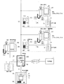
以下、本発明の集合住宅インターホンシステムを適用した最良の実施の形態例について、図面を参照して説明する。図1は、本発明の実施例による集合住宅インターホンシステムの全体(外観)構成を示すシステム説明図であり、このシステムは、通常、マンション等の集合住宅に設置されている。   DETAILED DESCRIPTION OF THE PREFERRED EMBODIMENTS A preferred embodiment to which an apartment house intercom system of the present invention is applied will be described below with reference to the drawings. FIG. 1 is a system explanatory diagram showing an overall (external) configuration of an apartment house intercom system according to an embodiment of the present invention, and this system is usually installed in an apartment house such as a condominium.

図1に示す集合住宅インターホンシステムは、集合住宅の集合玄関に設置される集合玄関機1と、集合玄関を施錠又は解錠するための集合玄関電気錠(図中においては「電気錠」とする。)2と、101号室、102号室、・・・のような集合住宅の複数の住戸(住戸内)にそれぞれ設置される居室親機3a、3b、・・・と、玄関側居室ラインL4a、L4b、・・・をそれぞれ経由して居室親機3a、3b、・・・に接続され、複数の住戸毎の住戸玄関にそれぞれ設置される玄関子機4a、4b、・・・と、電気錠側居室ラインL5a、L5b、・・・をそれぞれ経由して居室親機3a、3b、・・・に接続され、住戸玄関を施錠又は解錠するための玄関電気錠(図中においては「電気錠」とする。)5a、5b、・・・と、集合住宅の管理室(管理室内)に設置される管理室親機6と、地震の発生、津波の発生、近隣火災の発生等の緊急通報情報を生成する例えば、気象庁や防災管理会社等に設置される外部機器7と、電話回線、ISDN、ADSL、光通信網等の各種の汎用ネットワーク8と、集合玄関側制御ラインL1を経由して接続される集合玄関機1、電気錠側制御ラインL2を経由して接続される集合玄関電気錠2、居室側制御ラインL3を経由してバス接続される居室親機3a、3b、・・・、及び管理室側制御ラインL6を経由して接続される管理室親機6をそれぞれ制御するとともに、汎用ネットワーク8を経由して接続される外部機器7との間でデータ通信を行う制御機9とが設けられている。なお、居室親機3a、3b、・・・及び制御機9の間の接続の態様は、居室側制御ラインL3を経由したバス接続に限定されるものではなく、例えば、渡り配線により接続することもできる。   The collective housing intercom system shown in FIG. 1 includes a collective entrance machine 1 installed at a collective entrance of a collective housing, and a collective entrance electric lock for locking or unlocking the collective entrance (in the figure, “electric lock”). .) Rooms 2, 3, 3 b,..., And entrance side room line L 4 a, respectively installed in a plurality of dwelling units (inside the dwelling unit) such as rooms 101, 102,. .., And electric locks connected to the parent units 3a, 3b,... Via the L4b,. .. Are connected to the room master units 3a, 3b,... Via the side room lines L5a, L5b,..., And are used as door electric locks (in the figure, “electric locks”). And 5a, 5b, etc., and the apartment house management room (pipe Control room base unit 6 installed indoors) and generating emergency notification information such as earthquake occurrence, tsunami occurrence, neighborhood fire occurrence, etc. For example, external equipment 7 installed in the Japan Meteorological Agency or disaster management company, etc. Connected to various general-purpose networks 8 such as a telephone line, ISDN, ADSL, optical communication network, etc., via the collective entrance side control line L1 connected via the collective entrance side control line L1, and the electric lock side control line L2. .., And management room base unit 6 connected via the control room side control line L6. There is provided a controller 9 that controls each of them and performs data communication with an external device 7 connected via a general-purpose network 8. It should be noted that the mode of connection between the room master units 3a, 3b,... And the controller 9 is not limited to bus connection via the room side control line L3. You can also.

集合玄関機1は、集合玄関に居る人物、例えば、来訪者が、複数の住戸のうち特定の住戸内に在室の居住者又は管理室内に在室の管理人を呼び出して通話を成立させるためのものであり、操作部100、表示部101、カメラ部102及び通話部103を有している。ここで、操作部100は、来訪者が所定の呼出操作を行うものであり、例えば、表示部101の前面に配置されたタッチパネル上の操作ボタンで構成されている。また、表示部101は、操作部100にて行われる呼出操作の操作情報等を表示するためのものであり、例えば、LCD、PDP、有機ELディスプレイ等の各種の出画表示媒体で構成されている。また、カメラ部102は、呼出操作を行った来訪者の映像や集合玄関の周囲近傍の映像(監視映像)を撮像するためのものであり、例えば、CCD、CMOS等の各種の撮像素子媒体で構成されている。さらに、通話部103は、来訪者が居住者又は管理人との間で通話を成立させるための音声(送話音声、受話音声)を入出力するものであり、例えば、マイク及びスピーカで構成されている。なお、集合玄関機1には、前述の各機能の他に、通常、集合玄関電気錠2を施錠又は解錠するための機能が備えられている。   The collective entrance machine 1 is for a person at the collective entrance, for example, a visitor, to call a resident in a specific residence among a plurality of dwelling units or a manager in the control room to establish a call. An operation unit 100, a display unit 101, a camera unit 102, and a call unit 103. Here, the operation unit 100 is for a visitor to perform a predetermined call operation, and is configured with, for example, operation buttons on a touch panel arranged on the front surface of the display unit 101. The display unit 101 is for displaying operation information and the like of a call operation performed by the operation unit 100. For example, the display unit 101 includes various image display media such as an LCD, a PDP, and an organic EL display. Yes. The camera unit 102 is for capturing images of visitors who have performed a call operation and images around the entrance hall (surveillance images). It is configured. Furthermore, the call unit 103 inputs and outputs voices (sending voice and incoming voice) for a visitor to establish a call with a resident or a manager, and includes, for example, a microphone and a speaker. ing. In addition to the above-described functions, the collective entrance machine 1 is usually provided with a function for locking or unlocking the collective entrance electric lock 2.

居室親機3a、3b、・・・はそれぞれ同様な構成で個別の居室番号が割り当てられており、集合玄関に居る来訪者、自住戸の住戸玄関に居る来訪者及び管理室内に在室の管理人のうち何れかの人物からの呼び出しが報知され、この呼び出しに応答した居住者が通話を成立させるためのものであり、表示部300、操作部301及び通話部302を有している。ここで、表示部300は、集合玄関機1のカメラ部102又は玄関子機4a、4b、・・・の後述するカメラ部401にて撮像された映像を出画するとともに、集合玄関に居る来訪者、自住戸の住戸玄関に居る来訪者及び管理室内に在室の管理人のうち何れかの人物からの呼び出しがある旨の呼出情報、地震の発生、津波の発生、近隣火災の発生等の緊急通報情報をそれぞれ表示し、さらには、操作部301の操作情報等を表示するためのものであり、例えば、LCD、PDP、有機ELディスプレイ等の各種の出画表示媒体で構成されている。また、操作部301は、来訪者及び管理人のうち何れかの人物からの呼び出しに居住者が応答し、通話を成立させるための所定の応答操作と、居住者が集合玄関電気錠2又は自住戸の玄関電気錠5a、5b、・・・を解錠させるための所定の解錠操作と、居住者が住戸に在室又は不在であるかを設定するための所定の設定操作が行われるものであり、例えば、表示部300の前面に配置されたタッチパネル上の操作ボタンで構成されている。さらに、通話部302は、居住者が来訪者又は管理人との間で通話を成立させるための音声(送話音声、受話音声)を入出力するものであり、例えば、マイク302a、スピーカ302b及びハンドセット302cで構成されている。なお、操作部301は、前述の操作機能の他に、通常、居住者が管理人を呼び出すための所定の呼出操作を行うことができる。また、通話部302を構成するスピーカ302bは、前述の通話機能の他に、来訪者及び管理人のうち何れかの人物からの呼び出しがある旨の呼出音や音声メッセージ等や、地震の発生、津波の発生、近隣火災の発生等の緊急通報情報を警報発報するための警報音や音声メッセージ等を出力することができる。   Each of the room master units 3a, 3b,... Has the same configuration and is assigned an individual room number. Visitors at the collective entrance, visitors at the entrance of the self-dwelling unit, and management of rooms in the control room A call from any one of the persons is notified, and a resident who responds to the call establishes a call, and includes a display unit 300, an operation unit 301, and a call unit 302. Here, the display unit 300 displays an image captured by the camera unit 401 (to be described later) of the camera unit 102 of the collective entrance machine 1 or the entrance slave units 4a, 4b,. Call information that there is a call from any of the persons in the control room, visitors who are at the entrance of the dwelling unit, or in the control room, the occurrence of an earthquake, the occurrence of a tsunami, the occurrence of a nearby fire, etc. This is for displaying emergency call information, and further for displaying operation information of the operation unit 301, and is composed of various image display media such as an LCD, a PDP, and an organic EL display. In addition, the operation unit 301 includes a predetermined response operation for the resident to respond to a call from any one of the visitor and the manager and establish a call, and the resident can perform the collective entrance electric lock 2 or A predetermined unlocking operation for unlocking the entrance electric locks 5a, 5b,... Of the dwelling unit and a predetermined setting operation for setting whether the resident is present or absent in the dwelling unit are performed. For example, it is composed of operation buttons on a touch panel arranged on the front surface of the display unit 300. Further, the call unit 302 inputs and outputs voices (sending voice and incoming voice) for a resident to establish a call with a visitor or a manager. For example, a microphone 302a, a speaker 302b, It consists of a handset 302c. In addition to the above-described operation functions, the operation unit 301 can normally perform a predetermined call operation for a resident to call an administrator. In addition to the above-described call function, the speaker 302b that constitutes the call unit 302 has a ringing tone or a voice message indicating that there is a call from either a visitor or an administrator, an occurrence of an earthquake, It is possible to output an alarm sound, a voice message or the like for issuing an alarm notification of emergency notification information such as the occurrence of a tsunami or the occurrence of a nearby fire.

玄関子機4a、4b、・・・はそれぞれ同様な構成であり、複数の住戸毎の住戸玄関に居る人物、例えば、来訪者が、住戸内に在室の居住者を呼び出して通話を成立させるためのものであり、操作部400、カメラ部401及び通話部402を有している。ここで、操作部400は、来訪者が所定の呼出操作を行うものであり、例えば、呼出ボタンで構成されている。また、カメラ部401は、呼出操作を行った来訪者の映像や住戸玄関の周囲近傍の映像(監視映像)を撮像するためのものであり、例えば、CCD、CMOS等の各種の撮像素子媒体で構成されている。さらに、通話部402は、来訪者が居住者との間で通話を成立させるための音声(送話音声、受話音声)を入出力するものであり、例えば、マイク及びスピーカで構成されている。   Each of the entrance cordless handsets 4a, 4b,... Has the same configuration, and a person, for example, a visitor at the entrance of each of the plurality of units calls a resident in the room to establish a call. And has an operation unit 400, a camera unit 401, and a call unit 402. Here, the operation unit 400 is for a visitor to perform a predetermined call operation, and includes, for example, a call button. In addition, the camera unit 401 is for capturing images of visitors who have performed a call operation and images around the entrance of the dwelling unit (monitoring images). It is configured. Furthermore, the call part 402 inputs / outputs a voice (sending voice, receiving voice) for a visitor to establish a call with a resident, and is composed of, for example, a microphone and a speaker.

管理室親機6は、集合玄関に居る来訪者又は複数の住戸のうち特定の住戸内に在室の居住者からの呼び出しが報知され、この呼び出しに応答した管理室内に在室の管理人が通話を成立させるとともに、管理人が、特定の住戸内に在室の居住者を呼び出して通話を成立させる、或いは複数の居住者に対して一斉呼び出しを行うものであり、表示部600、操作部601及び通話部602を有している。ここで、表示部600は、集合玄関機1のカメラ部102にて撮像された映像を出画するとともに、集合玄関に居る来訪者又は特定の住戸内に在室の居住者からの呼び出しがある旨の呼出情報を表示し、さらには、操作部601の操作情報等を表示するためのものであり、例えば、LCD、PDP、有機ELディスプレイ等の各種の出画表示媒体で構成されている。また、操作部601は、来訪者及び居住者のうち何れかの人物からの呼び出しに管理人が応答するための所定の応答操作が行われるものであり、例えば、表示部600の前面に配置されたタッチパネル上の操作ボタンで構成されている。さらに、通話部602は、管理人が来訪者又は居住者との間で通話を成立させるための音声(送話音声、受話音声)を入出力するものであり、例えば、マイク、スピーカ及びハンドセットで構成されている。なお、操作部601は、前述の操作機能の他に、管理人が居住者を呼び出す(一斉呼び出しを含む。)ための所定の呼出操作を行うことができる。また、通話部602を構成するスピーカは、前述の通話機能の他に、来訪者又は居住者からの呼び出しがある旨の呼出音や音声メッセージ等を出力することができる。   The management room master unit 6 is notified of a call from a resident in a specific residence among a visitor or a plurality of dwelling units, and a manager in the management room responds to this call. In addition to establishing a call, a manager calls a resident in a room in a specific dwelling unit to establish a call, or makes a simultaneous call to a plurality of residents. The display unit 600, the operation unit 601 and a communication unit 602. Here, the display unit 600 displays an image picked up by the camera unit 102 of the collective entrance machine 1 and a call from a visitor who is in the collective entrance or a resident in a specific dwelling unit. In order to display the call information to the effect, and further to display the operation information of the operation unit 601, for example, it is configured by various image display media such as an LCD, a PDP, and an organic EL display. The operation unit 601 performs a predetermined response operation for an administrator to respond to a call from any one of a visitor and a resident, and is disposed on the front surface of the display unit 600, for example. It consists of operation buttons on the touch panel. Furthermore, the call unit 602 inputs and outputs voices (sending voices and incoming voices) for an administrator to establish a call with a visitor or a resident. For example, a microphone, a speaker, and a handset are used. It is configured. Note that the operation unit 601 can perform a predetermined call operation for an administrator to call a resident (including a simultaneous call) in addition to the operation functions described above. In addition to the above-described calling function, the speaker constituting the calling unit 602 can output a ringing tone or a voice message indicating that there is a call from a visitor or a resident.

次に、居室親機3a、3b、・・・の具体的な構成について、図2(a)のブロック図を参照して説明する。図2(a)に示す居室親機3a、3b、・・・はそれぞれ同様な構成であり、前述の表示部300と、操作部301と、通話部302を構成するマイク302a、スピーカ302b及びハンドセット302cと、映像処理部303と、音声処理部304と、CPU(以下、居室CPUという。)305と、3つのインターフェース(以下、それぞれ玄関側居室I/F、電気錠側居室I/F、制御機側居室I/Fという。)306、307、308とを有している。   Next, a specific configuration of the room master units 3a, 3b,... Will be described with reference to the block diagram of FIG. 2A have the same configuration, and the display unit 300, the operation unit 301, the microphone 302a, the speaker 302b, and the handset that configure the call unit 302 described above. 302c, a video processing unit 303, an audio processing unit 304, a CPU (hereinafter referred to as a living room CPU) 305, and three interfaces (hereinafter referred to as an entrance side room I / F, an electric lock side room I / F, and a control, respectively) It is called the machine side room I / F.) 306, 307, 308.

この居室親機3a、3b、・・・において、操作部301には、来訪者及び管理人のうち何れかの人物からの呼び出しに居住者が応答し通話を成立させる、或いは、成立中の通話を終了させるために操作する通話ボタン301aと、居住者が集合玄関電気錠2又は自住戸の玄関電気錠5a、5b、・・・を解錠させるために操作する解錠ボタン301bと、居住者が住戸内に在室又は不在であるかを設定するために操作する在室・不在ボタン301cとが備えられている。   In the living room master units 3a, 3b,..., The resident responds to a call from any one of the visitors and the manager in the operation unit 301 to establish a call, or a call in progress. A call button 301a operated to end the operation, an unlock button 301b operated by the resident to unlock the collective entrance electric lock 2 or the entrance electric locks 5a, 5b,. A presence / absence button 301c that is operated to set whether the user is present or absent in the dwelling unit is provided.

映像処理部303は、表示部300に出画させる映像であり集合玄関機1又は自住戸の玄関子機4a、4b、・・・から伝送されてくる映像信号を信号処理する例えば、FM復調、増幅等を行うためのものである。   The video processing unit 303 is a video to be displayed on the display unit 300 and performs signal processing on a video signal transmitted from the collective entrance machine 1 or the entrance unit 4a, 4b,... It is for performing amplification and the like.

音声処理部304は、通話部302を構成するマイク302a又はハンドセット302cのマイクに入力された居住者の音声(送話音声)であり電気信号に信号処理された音声信号を信号処理する例えば、4線/2線変換、増幅等を行うとともに、通話部302を構成するスピーカ302b又はハンドセット302cのレシーバから出力させる来訪者又は管理人の音声(受話音声)である音声信号を信号処理する例えば、2線/4線変換、増幅等を行うためのものである。   The voice processing unit 304 performs signal processing on a voice signal that is a resident's voice (transmission voice) input to the microphone 302a or the microphone of the handset 302c constituting the call unit 302 and is processed into an electrical signal, for example, 4 For example, 2 or 2 line conversion, amplification, etc., and signal processing of a voice signal that is a voice (received voice) of a visitor or a manager to be output from a speaker 302b or a receiver of the handset 302c constituting the call unit 302 This is for performing line / 4-line conversion, amplification, and the like.

居室CPU305は、居室親機3a、3b、・・・の構成各部を制御するためのものである。具体的な制御の一例として、居室CPU305は、操作部301を構成する在室・不在ボタン301cの操作を検出し、検出された操作情報である在室又は不在の設定情報に自機器の居室番号を付加して制御機9に送出することができる。また、居室CPU305は、操作部301を構成する解錠ボタン301bの操作又は制御機9の制御を検出し、自住戸の玄関電気錠5a、5b、・・・を解錠することができる。   The room CPU 305 is for controlling each component of the room master units 3a, 3b,. As an example of specific control, the room CPU 305 detects the operation of the presence / absence button 301c constituting the operation unit 301, and the room number of the own device is included in the presence / absence setting information that is the detected operation information. Can be added and sent to the controller 9. Moreover, the room CPU 305 can detect the operation of the unlock button 301b constituting the operation unit 301 or the control of the controller 9, and unlock the entrance electric locks 5a, 5b,.

玄関側居室I/F306は、玄関側居室ラインL4a、L4b、・・・から映像処理部303への信号伝送路と、玄関側居室ラインL4a、L4b、・・・及び音声処理部304の間の信号伝送路(通話路)と、玄関側居室ラインL4a、L4b、・・・及び居室CPU305の間の信号伝送路とをそれぞれ形成するためのものである。また、電気錠側居室I/F307は、居室CPU305から電気錠側居室ラインL5a、L5b、・・・への信号伝送路を形成するためのものである。さらに、制御機側居室I/F308は、居室側制御ラインL3から映像処理部303への信号伝送路と、居室側制御ラインL3及び音声処理部304の間の信号伝送路(通話路)と、居室側制御ラインL3及び居室CPU305の間の信号伝送路とをそれぞれ形成するためのものである。   The entrance side living room I / F 306 is located between the entrance side living room lines L4a, L4b,... To the image processing unit 303, and between the entrance side living room lines L4a, L4b,. A signal transmission path (speech path) and a signal transmission path between the entrance-side room lines L4a, L4b,. The electric lock side room I / F 307 is for forming a signal transmission path from the room CPU 305 to the electric lock side room lines L5a, L5b,. Further, the controller side room I / F 308 includes a signal transmission path from the room side control line L3 to the video processing unit 303, a signal transmission path (speech path) between the room side control line L3 and the audio processing unit 304, and This is for forming a signal transmission path between the room-side control line L3 and the room CPU 305, respectively.

次に、制御機9の具体的な構成について、図2(b)のブロック図を参照して説明する。図2(b)に示す制御機9は、記憶部900、CPU(以下、制御機CPUという。)901、及び5つのインターフェース(以下、それぞれ集合玄関側制御機I/F、電気錠側制御機I/F、居室側制御機I/F、管理室側制御機I/F、ネットワーク側制御機I/Fという。)902、903、904、905、906を有している。   Next, a specific configuration of the controller 9 will be described with reference to the block diagram of FIG. 2B includes a storage unit 900, a CPU (hereinafter referred to as a controller CPU) 901, and five interfaces (hereinafter referred to as a collective entrance side controller I / F and an electric lock side controller, respectively). I / F, living room side controller I / F, management room side controller I / F, network side controller I / F.) 902, 903, 904, 905, 906.

この制御機9において、記憶部900は、制御機CPU901により制御され、居室親機3a、3b、・・・の操作部301を構成する在室・不在ボタン301cの操作を検出して居室CPU305にて生成される在室又は不在の設定情報を記憶するためのものであり、例えば、RAM、EEPROM等の各種の記憶媒体で構成されている。   In this controller 9, the storage unit 900 is controlled by the controller CPU 901, detects the operation of the presence / absence button 301 c constituting the operation unit 301 of the living room master units 3 a, 3 b,. For example, it is configured to store various types of storage media such as RAM and EEPROM.

制御機CPU901は、制御機9及び当該システム全体を制御するためのものである。具体的な制御の一例として、制御機901は、外部機器7からの緊急通報情報が受信されたとき記憶部900の記憶内容を参照し、居室親機3a、3b、・・・の操作部301を構成する在室・不在ボタン301cの操作により在室の設定が行われている住戸の玄関電気錠5a、5b、・・・を解錠させるための解錠要求信号を生成することができる。   The controller CPU 901 is for controlling the controller 9 and the entire system. As an example of specific control, the controller 901 refers to the storage content of the storage unit 900 when emergency notification information from the external device 7 is received, and the operation unit 301 of the room master units 3a, 3b,. The unlock request signal for unlocking the entrance electric locks 5a, 5b,... Of the dwelling unit where the occupancy is set can be generated by operating the occupancy / absence button 301c.

集合玄関側制御機I/F902は、制御機CPU901及び集合玄関側制御ラインL1の間の信号伝送路を形成するためのものである。また、電気錠側制御機I/F903は、制御機CPU901から電気錠側制御ラインL2への信号伝送路を形成するためのものである。また、居室側制御機I/F904は、制御機CPU901及び居室側制御ラインL3の間の信号伝送路を形成するためのものである。また、管理室側制御機I/F905は、制御機CPU901及び管理室側制御ラインL6の間の信号伝送路を形成するためのものである。さらに、ネットワーク側I/F906は、汎用ネットワーク8から制御機CPU901への信号伝送路を形成するためのものである。   The collective entrance side controller I / F 902 is for forming a signal transmission path between the controller CPU 901 and the collective entrance side control line L1. The electric lock side controller I / F 903 is for forming a signal transmission path from the controller CPU 901 to the electric lock side control line L2. The room-side controller I / F 904 is for forming a signal transmission path between the controller CPU 901 and the room-side control line L3. The management room side controller I / F 905 is for forming a signal transmission path between the controller CPU 901 and the management room side control line L6. Further, the network side I / F 906 is for forming a signal transmission path from the general-purpose network 8 to the controller CPU 901.

このように構成された本発明の実施例による集合住宅インターホンシステムにおいて、以下、具体的な動作について説明する。なお、本発明の実施例において、集合玄関に居る来訪者が管理室内に在室の管理人を呼び出して通話を成立させる動作と、特定の住戸内に在室の居住者が管理人を呼び出して通話を成立させる動作と、管理人が特定の居住者を呼び出して通話を成立させる動作と、管理人が一斉放送を行う動作とはそれぞれ、マンション等の集合住宅に設置される各種のインターホンシステムにおいて公知の技術事項であるため、説明は省略するものとする。   In the apartment house intercom system according to the embodiment of the present invention configured as described above, a specific operation will be described below. In the embodiment of the present invention, a visitor at the collective entrance calls an administrator in the management room to establish a call, and a resident in the specific residence calls the administrator. The operation to establish a call, the operation in which a manager calls a specific resident and establishes a call, and the operation in which a manager broadcasts broadcasts in various intercom systems installed in apartment houses and other apartments. Since this is a known technical matter, the description thereof will be omitted.

図1、図2(a)に示す居室親機3a、3b、・・・がそれぞれ設置される住戸の居住者は、自らが住戸内に在室又は不在であるかの設定を、操作部301を構成する在室・不在ボタン301cを操作して行うことができる。この操作を検出した居室CPU305は、在室又は不在の設定情報に自機器の居室番号を付加した居住者在室・不在設定信号を生成し、制御機側居室I/F308、居室側制御ラインL3、図2(b)に示す制御機9の居室側制御機I/F904を経由して制御機CPU901に送出する。なお、居室CPU305にて生成された居住者在室・不在設定信号は、制御機9の制御機CPU901のみならず、制御機側居室I/F308、居室側制御ラインL3、設定元を除く他の当該居室親機の制御機側居室I/F308を経由して居室CPU305に送出されるものの、設定元を除く他の当該居室親機の居室CPU305では、受信した居住者在室・不在設定信号が制御機9の制御機CPU901からの出力信号でないために無効な信号であると判断して何ら動作処理を行わない。   The resident of the dwelling unit in which the living room master units 3a, 3b,... Shown in FIG. 1 and FIG. 2 (a) are respectively installed sets whether or not he / she is present or absent in the dwelling unit. Can be performed by operating the presence / absence button 301c. Upon detecting this operation, the room CPU 305 generates a resident occupancy / absence setting signal in which the occupancy number of the own device is added to the presence / absence setting information, and the controller side room I / F 308, room side control line L3 Then, the data is sent to the controller CPU 901 via the room-side controller I / F 904 of the controller 9 shown in FIG. The occupant presence / absence setting signal generated by the room CPU 305 is not limited to the controller CPU 901 of the controller 9, but the controller side room I / F 308, the room side control line L3, and other than the setting source. Although it is sent to the room CPU 305 via the controller side room I / F 308 of the room base unit, the room occupancy CPU 305 of the other room base unit other than the setting source receives the resident presence / absence setting signal received. Since it is not an output signal from the controller CPU 901 of the controller 9, it is determined that the signal is invalid and no operation processing is performed.

図2(b)に示す制御機9の制御機CPU901は、受信した居住者在室・不在設定信号を記憶部900に送出することにより、居室親機3a、3b、・・・がそれぞれ設置される住戸の居住者が住戸内に在室又は不在であるかの設定情報を、居室番号に割り当てて記憶部900に記憶させることができ、この記憶内容は、居住者在室・不在設定信号が受信される毎に書き換えられるものである。   The controller CPU 901 of the controller 9 shown in FIG. 2 (b) sends out the resident occupancy / absence setting signal to the storage unit 900, whereby the occupant parent units 3a, 3b,. The setting information as to whether the resident of the dwelling unit is present or absent in the dwelling unit can be assigned to the living room number and stored in the storage unit 900. This stored content is stored in the resident occupancy / absence setting signal. It is rewritten every time it is received.

なお、図2(b)に示す制御機9の記憶部900に記憶された設定情報は、図1に示す管理室親機6の操作部601の使用による所定の読出操作を検出した制御機CPU901の制御(詳述せず。)、或いは制御機CPU901が有する計時機能による所定のタイミングで読み出すことができる。また、制御機CPU901の制御により記憶部900から読み出された設定情報は、管理室側制御機I/F905、管理室側制御ラインL6を経由して管理室親機6に伝送され、表示部600に表示されるため、管理人にとっては、全住戸の居住者について住戸内に在室又は不在であるかを容易に確認することができる。   Note that the setting information stored in the storage unit 900 of the controller 9 shown in FIG. 2B is the controller CPU 901 that has detected a predetermined read operation by using the operation unit 601 of the management room master unit 6 shown in FIG. Can be read at a predetermined timing by the control (not described in detail) or by the time counting function of the controller CPU 901. The setting information read from the storage unit 900 by the control of the control unit CPU 901 is transmitted to the management room base unit 6 via the management room side control unit I / F 905 and the management room side control line L6, and is displayed on the display unit. Since it is displayed in 600, it is possible for the manager to easily confirm whether the occupants of all the dwelling units are present or absent in the dwelling units.

次に、居住者による在室・不在の設定・記憶の動作が予め行われている状態において、集合玄関に居る来訪者が特定の居住者を呼び出して通話を成立させるにあたり、ここでは、居室親機3aが設置される住戸の居住者を呼び出して通話を成立させるために、図1に示す集合玄関機1の操作部100を使用して所定の呼出操作を行うと、この集合玄関機1では、居室親機3aを指定するための居室番号を付加した呼出信号が生成され、集合玄関側制御ラインL1、制御機9の集合玄関側制御機I/F902を経由して制御機CPU901に伝送されるとともに、能動に制御されたカメラ部102にて撮像された映像である電気信号の映像信号が、呼出信号と同一の信号伝送路を経由して制御機9の制御御CPU901に伝送される。   Next, in the state where the occupant has set up and stored the presence / absence in advance, the visitor at the collective entrance calls a specific resident and establishes a call. When a predetermined call operation is performed using the operation unit 100 of the collective entrance machine 1 shown in FIG. 1 in order to call a resident of the dwelling unit in which the machine 3a is installed and establish a call, the collective entrance machine 1 A call signal with a room number for designating the room master 3a is generated and transmitted to the controller CPU 901 via the collective entrance control line L1 and the collective entrance controller I / F 902 of the controller 9. At the same time, the video signal of the electrical signal, which is the video imaged by the actively controlled camera unit 102, is transmitted to the control CPU 901 of the controller 9 via the same signal transmission path as the calling signal.

図2(b)に示す制御機9の制御機CPU901は、受信した呼出信号及び映像信号のうち当該呼出信号に付加されている居室番号に割り当てられて記憶部900に予め記憶されている居室親機3aが設置される住戸の居住者が在室又は不在であるかの設定情報を読み出し、読み出された設定情報が在室である場合には、受信した呼出信号を、居室側制御機I/F904、居室側制御ラインL3、図2(a)に示す全ての居室親機3a、3b、・・・の制御機側居室I/F308を経由して居室CPU305にそれぞれ送出するとともに、同様に受信した映像信号を、居室側制御機I/F904、居室側制御ラインL3、全ての居室親機3a、3b、・・・の制御機側居室I/F308を経由して映像処理部303にそれぞれ送出する。一方、読み出された設定情報が不在である場合には、受信した呼出信号及び映像信号を、全ての居室親機3a、3b、・・・の居室CPU305及び映像処理部303にそれぞれ送出することはなく、不在時呼び出しの呼出情報と受信した映像信号とを記憶部900に記憶させることができる。なお、記憶部900に記憶された不在時呼び出しの呼出情報は、通常、外出先から自住戸に帰宅しようとする居住者が、図1に示す集合玄関機1の操作部100を使用して所定の操作を行うことにより読み出され、表示部101に表示されるものである。   The controller CPU 901 of the controller 9 shown in FIG. 2B assigns the room parent assigned to the room number added to the call signal out of the received call signal and video signal and is stored in advance in the storage unit 900. The setting information as to whether the resident of the dwelling unit in which the machine 3a is installed is present or absent is read. If the read setting information is present, the received call signal is sent to the room-side controller I. / F904, the room-side control line L3, and all of the room base units 3a, 3b,... Shown in FIG. The received video signal is sent to the video processing unit 303 via the room-side controller I / F 904, the room-side control line L3, the controller-side room I / F 308 of all the room master units 3a, 3b,. Send it out. On the other hand, when the read setting information is absent, the received call signal and video signal are sent to the room CPU 305 and the video processing unit 303 of all the room master units 3a, 3b,. Rather, the call information for the absence call and the received video signal can be stored in the storage unit 900. In addition, the call information for the absence call stored in the storage unit 900 is usually determined by a resident who is going home from his / her home away from home while using the operation unit 100 of the collective entrance 1 shown in FIG. Is read out and displayed on the display unit 101.

図2(a)に示す全ての居室親機3a、3b、・・・の居室CPU305はそれぞれ、受信した呼出信号に付加されている居室番号と自機器の居室番号とを照合し、当該居室番号が一致した場合にのみ通話部302を構成するスピーカ302bから呼出音や音声メッセージ等を出力させて集合玄関に居る来訪者からの呼び出しを報知するとともに、表示部300及び映像処理部303がそれぞれ能動となるように制御することにより、映像処理部303にて受信され信号処理された映像信号、すなわち、集合玄関機1のカメラ部102にて撮像された来訪者の映像を表示部300に出画させることができ、この表示部300には、集合玄関に居る来訪者からの呼び出しがある旨の呼出メッセージや絵データ等を表示させ、呼出報知を行うこともできる。ここでは、図2(b)に示す制御機9の記憶部900に在室の設定情報が記憶されている呼出先の居室親機3aのみ、前述の呼出報知及び映像の出画がそれぞれ行われることになる。   The room CPUs 305 of all the room base units 3a, 3b,... Shown in FIG. 2A collate the room number added to the received call signal with the room number of the own device, and the room number. Only when they match, the speaker 302b constituting the calling unit 302 outputs a ringing tone, a voice message, and the like to notify a call from a visitor at the main entrance, and the display unit 300 and the video processing unit 303 are active. The video signal received by the video processing unit 303 and processed by the video processing unit 303, that is, the video of the visitor captured by the camera unit 102 of the collective entrance 1 is displayed on the display unit 300. This display unit 300 displays a call message or picture data indicating that there is a call from a visitor at the entrance, and performs a call notification. It can be. Here, the above-mentioned call notification and video image display are performed only for the call-target room master unit 3a in which the room setting information is stored in the storage unit 900 of the controller 9 shown in FIG. It will be.

この後、図1、図2(a)に示す居室親機3aが設置される住戸内に在室の居住者は、集合玄関に居る来訪者からの呼び出しがあることを当該来訪者の判別と併せて確認し、通話を成立させるために操作部301を構成する通話ボタン301aを操作すると、この操作を検出した居室CPU305の制御及び図2(b)に示す制御機9の制御機CPU901の制御により、呼出先の居住者が使用する居室親機3aの通話部302を構成するマイク302a及びスピーカ302bと、音声処理部304、制御機側居室I/F308、居室側制御ラインL3、制御機9の居室側制御機I/F904、制御機CPU901、集合玄関側制御機I/F902、集合玄関側制御ラインL1を経由して呼出元の来訪者が使用する集合玄関機1の通話部103との間の信号伝送路が形成され、形成された信号伝送路を経由して音声信号を送受信させることで通話が成立し、特に、呼出先の居住者にとっては、呼出元の来訪者の映像を確認しながらの通話が可能となる。   After this, the resident in the room where the room master unit 3a shown in FIG. 1 and FIG. 2 (a) is installed is called the visitor's discrimination that there is a call from the visitor at the collective entrance. In addition, when the call button 301a constituting the operation unit 301 is operated to confirm and establish a call, the control of the room CPU 305 that detects the operation and the control of the controller CPU 901 of the controller 9 shown in FIG. Thus, the microphone 302a and the speaker 302b constituting the call unit 302 of the room master unit 3a used by the callee resident, the voice processing unit 304, the controller side room I / F 308, the room side control line L3, the controller 9 The communication unit 103 of the collective entrance 1 used by the caller visitor via the control unit I / F 904, the controller CPU 901, the collective entrance controller I / F 902, and the collective entrance control line L1. A signal transmission path is formed, and a voice call is transmitted / received via the formed signal transmission path to establish a call. In particular, for the callee resident, the caller visitor's video is displayed. Calls can be made while checking.

なお、前述までの説明では、図1、図2(a)に示す居室親機3aが設置される住戸内に在室の居住者が集合玄関に居る来訪者からの呼び出しに応答して通話を成立させる手段として、通話部302を構成するマイク302a及びスピーカ302bを適用したが、この通話手段に限定されず、応答操作として取り上げたハンドセット302cを適用することもできる。   In the above description, a resident in a room makes a call in response to a call from a visitor who is at the main entrance in the dwelling unit where the living room master unit 3a shown in FIGS. 1 and 2A is installed. Although the microphone 302a and the speaker 302b constituting the call unit 302 are applied as means for establishing, the present invention is not limited to the call means, and the handset 302c taken up as a response operation can also be applied.

また、図1、図2(a)に示す居室親機3aが設置される住戸内に在室の居住者は、例えば、前述の通話の成立中において呼出元の来訪者を集合住宅内に招き入れるにあたり、操作部301を構成する解錠ボタン301bを操作する。この操作を検出した居室CPU305は、集合玄関電気錠2を解錠させるための解錠要求信号を生成し、制御機側居室I/F308、居室側制御ラインL3、図2(b)に示す制御機9の居室側制御機I/F904を経由して制御機CPU901に送出する。なお、居室CPU305にて生成された解錠要求信号は、前述の居住者在室・不在設定信号と同様、制御機9の制御機CPU901のみならず解錠要求元を除く他の当該居室親機の居室親機CPU305に送出されるものの、解錠要求元を除く他の当該居室親機の居室親機CPU305では、受信した解錠要求信号が制御機9の制御機CPU901からの出力信号でないために無効な信号であると判断して何ら動作処理を行わない。   In addition, a resident who is resident in the dwelling unit in which the base unit 3a shown in FIG. 1 and FIG. 2A is installed invites a caller visitor into the housing complex during the establishment of the above-described call, for example. In this case, the unlock button 301b constituting the operation unit 301 is operated. The room CPU 305 that has detected this operation generates an unlock request signal for unlocking the collective entrance electric lock 2, and controls the controller side room I / F 308, the room side control line L3, and the control shown in FIG. It is sent to the controller CPU 901 via the room side controller I / F 904 of the machine 9. Note that the unlock request signal generated by the room CPU 305 is not limited to the controller CPU 901 of the controller 9 as well as the above-mentioned resident presence / absence setting signal, but other room base units other than the unlock request source. However, since the unlock request signal received is not an output signal from the controller CPU 901 of the controller 9, the unlock request signal is not output from the controller CPU 901 of the controller 9. It is determined that the signal is invalid, and no operation processing is performed.

図2(b)に示す制御機9の制御機CPU901は、受信した解錠要求信号をもとに居室親機3aが設置される住戸内に在室の居住者による解錠要求があったことを検出し、集合玄関電気錠2を解錠させるための解錠制御信号を生成し、電気錠側制御機I/F903、電気錠側制御ラインL2を経由して集合玄関電気錠2に送出することにより、この集合玄関電気錠2が(一定時間)解錠され、来訪者は、集合玄関電気錠2が解錠された集合玄関から集合住宅内に入り居室親機3aが設置される住戸に向かうことができる。   The controller CPU 901 of the controller 9 shown in FIG. 2B has received a request for unlocking by a resident in the room where the living room master unit 3a is installed based on the received unlocking request signal. Is detected, an unlock control signal for unlocking the collective entrance electric lock 2 is generated, and sent to the collective entrance electric lock 2 via the electric lock side controller I / F 903 and the electric lock side control line L2. Thus, the collective entrance electric lock 2 is unlocked (for a certain period of time), and a visitor enters the collective housing from the collective entrance where the collective entrance electric lock 2 is unlocked, and enters the dwelling unit where the living room master unit 3a is installed. I can head.

次に、前述のように集合玄関から集合住宅内に入り、図1に示す居室親機3aが設置される住戸の住戸玄関に辿り着いた来訪者が居住者を呼び出して通話を成立させるにあたり、玄関子機4aの操作部400を使用して所定の呼出操作を行うと、この玄関子機4aでは呼出信号が生成され、玄関側居室ラインL4a、図2(a)に示す居室親機3aの玄関側居室I/F306を経由して居室CPU305に伝送されるとともに、能動に制御されたカメラ部401にて撮像された映像である電気信号の映像信号が、玄関側居室ラインL4a、玄関側居室I/F306を経由して映像処理部303に伝送される。   Next, when a visitor who enters the apartment house from the entrance hall and arrives at the entrance hall of the residence unit where the room master unit 3a shown in FIG. 1 is installed calls the resident and establishes a call, When a predetermined calling operation is performed using the operation unit 400 of the entrance cordless handset 4a, a calling signal is generated in the entrance cordless handset 4a, and the entrance side living room line L4a, the room master set 3a shown in FIG. A video signal of an electrical signal which is transmitted to the room CPU 305 via the entrance side living room I / F 306 and imaged by the actively controlled camera unit 401 is input to the entrance side living room line L4a, the entrance side living room. It is transmitted to the video processing unit 303 via the I / F 306.

図2(a)に示す居室親機3aの居室CPU305は、呼出信号を受信すると通話部302を構成するスピーカ302から呼出音や音声メッセージ等を出力させて自住戸の住戸玄関に居る来訪者からの呼び出しを報知するとともに、表示部300及び映像処理部303がそれぞれ能動となるように制御することにより、映像処理部303にて受信され信号処理された映像信号、すなわち、玄関子機4aのカメラ部401にて撮像された来訪者の映像を表示部300に出画させることができ、この表示部300には、自住戸の住戸玄関に居る来訪者からの呼び出しがある旨の呼出メッセージや絵データ等を表示させ、呼出報知を行うこともできる。   When the room CPU 305 of the room base unit 3a shown in FIG. 2A receives the call signal, the room CPU 305 outputs a ringing tone, a voice message, etc. from the speaker 302 constituting the call unit 302, and from a visitor who is at the entrance of the dwelling unit. , And the display unit 300 and the video processing unit 303 are controlled so as to be active, so that the video signal received and processed by the video processing unit 303, that is, the camera of the front door unit 4a. The image of the visitor imaged by the unit 401 can be displayed on the display unit 300, and the display unit 300 displays a call message or a picture indicating that there is a call from a visitor at the entrance of the dwelling unit. Data or the like can be displayed to make a call notification.

この後、図1、図2(a)に示す居室親機3aが設置される住戸内に在室の居住者は、自住戸の住戸玄関に居る来訪者からの呼び出しがあることを当該来訪者の判別と併せて確認し、通話を成立させるために操作部301を構成する通話ボタン301aを操作すると、この操作を検出した居室CPU305の制御により、呼出先の居住者が使用する居室親機3aの通話部302を構成するマイク302a及びスピーカ302bと、音声処理部304、玄関側親機I/F306、玄関側居室ラインL4aを経由して呼出元の来訪者が使用する図1に示す玄関子機4aの通話部402との間の信号伝送路が形成され、形成された信号伝送路を経由して音声信号を送受信させることで通話が成立し、特に、呼出先の居住者にとっては、呼出元の来訪者の映像を確認しながらの通話が可能となる。   Thereafter, the resident in the room where the main unit 3a shown in FIG. 1 and FIG. 2 (a) is installed is called by the visitor who is at the entrance of the own unit. When the call button 301a that constitutes the operation unit 301 is operated in order to establish a call, the room master unit 3a used by the callee resident is controlled by the room CPU 305 that detects the operation. 1 used by a caller visitor via a microphone 302a and a speaker 302b, a voice processing unit 304, an entrance-side master unit I / F 306, and an entrance-side room line L4a. A signal transmission path is formed between the communication unit 402 of the machine 4a and a call is established by transmitting and receiving a voice signal via the formed signal transmission path. Original visitor It is possible to call while checking the image.

なお、前述までの説明では、図1、図2(a)に示す居室親機3aが設置される住戸内に在室の居住者が自住戸の住戸玄関に居る来訪者からの呼び出しに応答して通話を成立させる手段として、通話部302を構成するマイク302a及びスピーカ302bを適用したが、この通話手段に限定されず、応答操作として取り上げたハンドセット302cを適用することもできる。   In the above description, a resident in a room in the dwelling unit in which the living room master unit 3a shown in FIGS. 1 and 2 (a) is installed responds to a call from a visitor who is at the dwelling entrance of the own dwelling unit. As a means for establishing a call, the microphone 302a and the speaker 302b constituting the call unit 302 are applied. However, the present invention is not limited to this call means, and the handset 302c taken up as a response operation can also be applied.

また、図1、図2(a)に示す居室親機3aが設置される住戸内に在室の居住者は、例えば、前述の通話の成立中において呼出元の来訪者を自住戸内に招き入れるにあたり、操作部301を構成する解錠ボタン301bを操作する。この操作を検出した居室CPU305は、自住戸の玄関電気錠5aを解錠させるための解錠制御信号を生成し、電気錠側居室I/F307、電気錠側居室ラインL5aを経由して玄関電気錠5aに送出することにより、この玄関電気錠5aが(一定時間)解錠され、来訪者は、玄関電気錠5aが解錠された住戸玄関から住戸内に入ることができる。   In addition, a resident in the residence unit in which the room master unit 3a shown in FIG. 1 and FIG. 2A is installed invites a caller visitor to the residence unit while the above-described call is established, for example. In this case, the unlock button 301b constituting the operation unit 301 is operated. Upon detecting this operation, the room CPU 305 generates an unlock control signal for unlocking the entrance electric lock 5a of the self-dwelling unit, and uses the electric lock side room I / F 307 and the electric lock side room line L5a to enter the entrance electricity. By sending the lock to the lock 5a, the entrance electric lock 5a is unlocked (for a fixed time), and a visitor can enter the dwelling unit from the entrance where the entrance electric lock 5a is unlocked.

次に、居住者による在室・不在の設定・記憶の動作が予め行われている状態において、気象庁や防災管理会社等に設置される図1に示す外部機器7にて地震の発生、津波の発生、近隣火災の発生等の緊急通報情報が生成されると、この緊急通報情報は、汎用ネットワーク8、図2(b)に示す制御機9のネットワーク側制御機I/F906を経由して制御機CPU901に伝送される。   Next, in the state where the setting of occupancy / absence by the resident is performed in advance, the occurrence of an earthquake or tsunami in the external device 7 shown in FIG. When emergency notification information such as the occurrence of an outbreak or the occurrence of a nearby fire is generated, this emergency notification information is controlled via the general-purpose network 8 and the network-side controller I / F 906 of the controller 9 shown in FIG. Is transmitted to the machine CPU 901.

図2(b)に示す制御機9の制御機CPU901は、外部機器7からの緊急通報情報を受信すると、記憶部900に予め記憶されている居室親機3a、3b、・・・が設置される住戸の居住者が在室又は不在であるかの設定情報を読み出し、読み出された設定情報が在室である住戸を指定するための居室番号、在室である住戸の当該玄関電気錠を解錠させるための解錠要求信号及び前述の緊急通報情報を付加した緊急通報制御信号を生成する。この緊急通報制御信号は、制御機CPU901から居室側制御機I/F904、居室側制御ラインL3、図2(a)に示す全ての居室親機3a、3b、・・・の制御機側居室I/F308を経由して居室CPU305にそれぞれ伝送される。   When the controller CPU 901 of the controller 9 shown in FIG. 2B receives emergency call information from the external device 7, the room master units 3a, 3b,... Stored in advance in the storage unit 900 are installed. Read the setting information as to whether the resident of the dwelling unit is in the room or absent, and the read out setting information is the room number for designating the dwelling unit that is in the room, and the entrance electric lock of the dwelling unit in the room An unlock request signal for unlocking and an emergency call control signal to which the above emergency call information is added are generated. This emergency call control signal is sent from the controller CPU 901 to the room-side controller I / F 904, the room-side control line L3, the controller-side room I of all the room base units 3a, 3b,... Shown in FIG. / F308 to the room CPU 305, respectively.

図2(a)に示す全ての居室親機3a、3b、・・・の居室CPU305はそれぞれ、受信した緊急通報制御信号に付加されている居室番号と自機器の居室番号とを照合し、当該居室番号が一致した場合にのみ通話部302を構成するスピーカ302bから警報音や音声メッセージ等を出力させるとともに、警報メッセージや絵データ等を表示部300に表示させて地震の発生、津波の発生、近隣火災の発生等の緊急通報情報を警報発報し、さらには、自住戸の玄関電気錠5a、5b、・・・を解錠させるための解錠制御信号を生成することができる。   The room CPUs 305 of all the room base units 3a, 3b,... Shown in FIG. 2 (a) collate the room number added to the received emergency call control signal with the room number of the own device. Only when the room numbers match, an alarm sound or voice message is output from the speaker 302b constituting the call unit 302, and an alarm message or picture data is displayed on the display unit 300 to generate an earthquake, tsunami, An emergency notification information such as the occurrence of a nearby fire can be issued as an alarm, and further, an unlocking control signal for unlocking the entrance electric locks 5a, 5b,.

ここで、図1、図2(a)に示す居室親機3a、3b、・・・のうち例えば、前述のように居住者が住戸内に在室しており来訪者を招き入れることが可能な居室親機3aが在室である旨の設定情報と、その他の居室親機3b、・・・が不在である旨の設定情報とがそれぞれが制御機9の記憶部900に予め記憶されていたとすると、全ての居室親機3a、3b、・・・の居室CPU305のうち、居室親機3aの居室CPU305のみ受信した緊急通報制御信号に付加されている居室番号と自機器の居室番号とが一致し前述の警報発報が行われるとともに、自住戸の玄関電気錠5aを解錠させるための解錠制御信号が生成されるため、この解錠制御信号を、電気錠側居室I/F307、電気錠側居室ラインL5aを経由して玄関電気錠5aに送出することにより、玄関電気錠5aが通常の解錠時間よりも長く、或いは恒久的に解錠され、居住者は、住戸内から住戸外へと迅速に避難することができるとともに、外部からの救助活動が容易となるため、居住者の安全性が高められる。   Here, of the living room master units 3a, 3b,... Shown in FIG. 1 and FIG. 2 (a), for example, the resident is present in the dwelling unit as described above, and it is possible to invite visitors. It is assumed that the setting information indicating that the living room parent device 3a is present and the setting information indicating that the other living room parent devices 3b,... Are absent are stored in advance in the storage unit 900 of the controller 9. Then, among the room CPUs 305 of all the room base units 3a, 3b,..., The room number added to the emergency call control signal received only by the room CPU 305 of the room base unit 3a is equal to the room number of the own device. In addition, the above-mentioned alarm is issued and an unlocking control signal for unlocking the entrance electric lock 5a of the self-dwelling unit is generated, and this unlocking control signal is used as the electric lock side living room I / F 307, electric Sent to the entrance electric lock 5a via the lock side room L5a As a result, the entrance electric lock 5a is unlocked longer than the normal unlocking time or permanently, and the resident can evacuate quickly from the dwelling unit to the outside of the dwelling unit, as well as from the outside. As activities become easier, the safety of residents is increased.

なお、前述までの説明によれば、居住者による在室・不在の設定・記憶の動作が予め行われている状態における外部機器7からの緊急通報信号を受信した制御機9の制御機CPU901の制御として、居住者が在室である住戸の居室親機3a、3b、・・・にて緊急通報情報の警報発報を行い玄関電気錠5a、5b、・・・を解錠するための緊急通報制御信号を生成させたが、この制御に限定されるものではない。例えば、集合玄関機1の表示部101及び通話部103、管理室親機6の表示部600及び通話部602をそれぞれ使用して所定の警報発報を行うこともでき、また、緊急通報の重要度に応じて集合玄関電気錠2を解錠させることもでき、さらには、居住者が不在である住戸の居室親機3b、・・・にて緊急通報情報の警報発報を行うこともできる。   In addition, according to the above description, the controller CPU 901 of the controller 9 that has received the emergency notification signal from the external device 7 in a state where the occupant's presence / absence setting / storage operation is performed in advance. As a control, an emergency for unlocking the front door electric locks 5a, 5b,... Although the notification control signal is generated, it is not limited to this control. For example, a predetermined alarm can be issued using the display unit 101 and the communication unit 103 of the collective entrance 1 and the display unit 600 and the communication unit 602 of the management room base unit 6, respectively. Depending on the degree, it is possible to unlock the collective entrance electric lock 2, and further, it is possible to issue an alarm notification of emergency call information in the living room master unit 3 b of the dwelling unit where no resident is present. .

また、本発明の実施例による集合住宅インターホンシステムにおいては、記憶部900及び制御機CPU901を別体で制御機9に設けたが、この態様に限定されるものではない。例えば、記憶部900を制御機CPU901の内部に備えることもでき、回路構成が簡素化される。   Further, in the apartment house intercom system according to the embodiment of the present invention, the storage unit 900 and the controller CPU 901 are provided separately in the controller 9, but the present invention is not limited to this mode. For example, the storage unit 900 can be provided inside the controller CPU 901, and the circuit configuration is simplified.

さらに、本発明の実施例による集合住宅インターホンシステムにおいて、地震の発生、津波の発生、近隣火災の発生等の緊急通報情報を警報発報し、自住戸の玄関電気錠5a、5b、・・・を解錠させた後、居住者の安全性が確認された場合には、例えば、管理人による管理室親機6の操作部601の操作を検出した制御機9の制御機CPU901による居室親機3a、3b、・・・の居室CPU305への制御をもとに、玄関電気錠5a、5b、・・・を一斉施錠させることもできる。   Further, in the apartment house intercom system according to the embodiment of the present invention, the emergency notification information such as the occurrence of an earthquake, the occurrence of a tsunami, the occurrence of a nearby fire, etc. is issued as an alarm, and the entrance electric locks 5a, 5b,. In the case where the safety of the resident is confirmed after unlocking, for example, the room master unit by the controller CPU 901 of the controller 9 that detects the operation of the operation unit 601 of the manager room master 6 by the manager Based on the control of the room CPU 305 of 3a, 3b,..., The entrance electric locks 5a, 5b,.

本発明の集合住宅インターホンシステムにおいては、特定の実施の形態をもって説明してきたが、この形態に限定されるものでなく、本発明の効果を奏する限り、これまで知られた如何なる構成の集合住宅インターホンシステム、例えば、玄関子機4a、4b、・・・にカメラ部401が不備とされる当該玄関子機を有する集合住宅インターホンシステムや、管理室がなく管理室親機6が不要とされる集合住宅インターホンシステムであっても採用できるということはいうまでもないことである。   The apartment house intercom system of the present invention has been described with a specific embodiment. However, the present invention is not limited to this embodiment. As long as the effect of the present invention is exhibited, the apartment house intercom having any known configuration has been described. A system, for example, a collective housing intercom system having the entrance unit whose camera unit 401 is not provided in the entrance unit 4a, 4b,... Needless to say, even a residential intercom system can be adopted.

図1は、本発明の実施例による集合住宅インターホンシステムの全体(外観)構成を示すシステム説明図である。FIG. 1 is a system explanatory diagram showing an overall (external) configuration of an apartment house intercom system according to an embodiment of the present invention. 図2(a)は、本発明の実施例によるインターホンシステムにおいて、居室親機の具体的な構成を示すブロック図である。また、図2(b)は、本発明の実施例によるインターホンシステムにおいて、制御機の具体的な構成を示すブロック図である。FIG. 2A is a block diagram showing a specific configuration of the living room master unit in the intercom system according to the embodiment of the present invention. FIG. 2B is a block diagram showing a specific configuration of the controller in the intercom system according to the embodiment of the present invention.

1……集合玄関機
3a、3b、・・・ ……居室親機
301c……在室・不在ボタン
305……居室CPU
5a、5b、・・・ ……玄関電気錠
9……制御機
900……記憶部
901……制御機CPU
7……外部機器
1 ... Collective entrance machine 3a, 3b, ... Room parent machine 301c ... In-room / absence button 305 ... In-room CPU
5a, 5b,... ...... Entrance electric lock 9 ... Controller 900 ... Storage unit 901 ... Controller CPU
7 …… External equipment

Claims (1)

集合住宅の集合玄関に設置され来訪者が居住者を呼び出して通話を成立させるための集合玄関機(1)と、前記集合住宅の複数の住戸にそれぞれ設置され前記来訪者からの呼び出しに応答した前記居住者が通話を成立させるための居室親機(3a、3b、・・・)と、前記住戸の住戸玄関を施錠又は解錠させるための玄関電気錠(5a、5b、・・・)と、前記集合玄関機及び前記居室親機をそれぞれ制御するための制御機(9)とを設け、
前記制御機には、地震の発生、津波の発生、近隣火災の発生等の緊急通報情報を生成するための外部機器(7)が接続され、
前記居室親機には、前記居住者が住戸内に在室又は不在であるかを設定するための在室・不在ボタン(301c)と、前記在室・不在ボタンの操作を検出して前記在室又は前記不在の設定情報を生成するための居室CPU(305)とを備え、
前記制御機には、前記外部機器からの前記緊急通報情報が受信されたとき、前記居室親機の前記在室・不在ボタンの操作により前記在室の設定が行われている住戸の前記玄関電気錠を解錠させるための制御機CPU(901)と、前記居室親機の前記在室・不在ボタンの操作により前記居室CPUにて生成される前記設定情報を記憶するための記憶部(900)とを備え、
前記制御機の前記制御機CPUは、前記在室である旨の設定情報が前記記憶部に記憶されているとき、自住戸の当該玄関電気錠を通常の解錠時間よりも長く、或いは恒久的に解錠させることを特徴とする集合住宅インターホンシステム。
A multi-purpose entrance (1) installed at a multi-family house entrance to allow a visitor to call a resident and establish a call, and a multi-unit residential unit installed in each multi-family house responding to calls from the visitor Room occupants (3a, 3b,...) For the resident to establish a call, and door electric locks (5a, 5b,...) For locking or unlocking the dwelling entrance of the dwelling unit. And a controller (9) for controlling the collective entrance machine and the living room master unit,
The controller is connected to an external device (7) for generating emergency notification information such as the occurrence of an earthquake, the occurrence of a tsunami, the occurrence of a nearby fire,
The living room base unit detects the presence / absence button (301c) for setting whether the resident is present or absent in the dwelling unit, and the presence / absence button operation to detect the presence / absence button. A room CPU (305) for generating room or absence setting information,
When the emergency notification information is received from the external device, the controller is configured to set the occupancy of the dwelling unit by operating the occupancy / absence button of the occupant base unit. A controller CPU (901) for unlocking the lock, and a storage unit (900) for storing the setting information generated by the room CPU by operating the presence / absence button of the room master unit And
When the controller CPU of the controller stores the setting information indicating that it is in the room, the entrance electric lock of the self-dwelling unit is longer than the normal unlocking time or is permanent. An apartment intercom system characterized by having the door unlocked .
JP2007247365A 2007-09-25 2007-09-25 Apartment house intercom system Active JP4989395B2 (en)

Priority Applications (1)

Application Number Priority Date Filing Date Title
JP2007247365A JP4989395B2 (en) 2007-09-25 2007-09-25 Apartment house intercom system

Applications Claiming Priority (1)

Application Number Priority Date Filing Date Title
JP2007247365A JP4989395B2 (en) 2007-09-25 2007-09-25 Apartment house intercom system

Publications (2)

Publication Number Publication Date
JP2009081515A JP2009081515A (en) 2009-04-16
JP4989395B2 true JP4989395B2 (en) 2012-08-01

Family

ID=40655971

Family Applications (1)

Application Number Title Priority Date Filing Date
JP2007247365A Active JP4989395B2 (en) 2007-09-25 2007-09-25 Apartment house intercom system

Country Status (1)

Country Link
JP (1) JP4989395B2 (en)

Families Citing this family (6)

* Cited by examiner, † Cited by third party
Publication number Priority date Publication date Assignee Title
JP5433317B2 (en) * 2009-06-25 2014-03-05 パナソニック株式会社 Load control system
JP5608459B2 (en) * 2010-07-26 2014-10-15 パナソニック株式会社 Intercom system for housing complex
JP6830845B2 (en) * 2017-03-30 2021-02-17 アイホン株式会社 Intercom system
JP2018078649A (en) * 2018-01-17 2018-05-17 パナソニックIpマネジメント株式会社 Information system for multiple dwelling house
JP6697749B2 (en) * 2018-03-05 2020-05-27 パナソニックIpマネジメント株式会社 Information system for housing complex
JP7094829B2 (en) * 2018-08-21 2022-07-04 アイホン株式会社 Emergency call system

Family Cites Families (5)

* Cited by examiner, † Cited by third party
Publication number Priority date Publication date Assignee Title
JPH03221677A (en) * 1990-01-26 1991-09-30 Toshiba Corp Security system
JPH04361399A (en) * 1991-06-07 1992-12-14 Fujitsu General Ltd Multiple dwelling house management system
JPH08177281A (en) * 1994-12-21 1996-07-09 Matsushita Electric Works Ltd Apartment house control system
JP3661620B2 (en) * 2001-08-28 2005-06-15 松下電工株式会社 Apartment house management system with earthquake notification function
JP5021933B2 (en) * 2005-12-26 2012-09-12 アイホン株式会社 Apartment house intercom system

Also Published As

Publication number Publication date
JP2009081515A (en) 2009-04-16

Similar Documents

Publication Publication Date Title
JP4989395B2 (en) Apartment house intercom system
KR101725083B1 (en) Home network system and control method thereof
JP2008217438A (en) Multiple dwelling house management system coping with emergency earthquake flash
JP2007013671A (en) Multiple dwelling house interphone system
JP2004194111A (en) Home security system and method for the same
JP2008085850A (en) Intercom system
JP2000299740A (en) Interphone provided with transfer function
JP5364654B2 (en) Apartment house intercom system
JP5026865B2 (en) Apartment house security intercom system
JP5587813B2 (en) Intercom system for housing complex
JP5840511B2 (en) Apartment house intercom system
JP5367949B2 (en) Apartment house intercom system with security function
JP6706338B2 (en) Building controller and intercom system
JP2008182346A (en) Intercom system for apartment house
JP2009130522A (en) Condominium intercom system
JP2010050888A (en) Interphone system for multiple-dwelling houses
JP4006963B2 (en) Residential information board master unit, residential information panel secondary master unit, hands-free call system for collective housing
JP2011160105A (en) Master unit of intercom device, and intercom device
JP2006101328A (en) Apartment intercom system
JP4650439B2 (en) Apartment house management system for earthquake early warning
JP2009010696A (en) Intercom system
JP2004171383A (en) Composite board for alarm monitoring of apartment house
JP6830845B2 (en) Intercom system
JP2009077235A (en) Interphone system for apartment house
JP2007116630A (en) Multiple dwelling housing intercom system

Legal Events

Date Code Title Description
A621 Written request for application examination

Free format text: JAPANESE INTERMEDIATE CODE: A621

Effective date: 20100720

A977 Report on retrieval

Free format text: JAPANESE INTERMEDIATE CODE: A971007

Effective date: 20111107

A131 Notification of reasons for refusal

Free format text: JAPANESE INTERMEDIATE CODE: A131

Effective date: 20111115

A521 Request for written amendment filed

Free format text: JAPANESE INTERMEDIATE CODE: A523

Effective date: 20111214

TRDD Decision of grant or rejection written
A01 Written decision to grant a patent or to grant a registration (utility model)

Free format text: JAPANESE INTERMEDIATE CODE: A01

Effective date: 20120403

A01 Written decision to grant a patent or to grant a registration (utility model)

Free format text: JAPANESE INTERMEDIATE CODE: A01

A61 First payment of annual fees (during grant procedure)

Free format text: JAPANESE INTERMEDIATE CODE: A61

Effective date: 20120427

R150 Certificate of patent or registration of utility model

Ref document number: 4989395

Country of ref document: JP

Free format text: JAPANESE INTERMEDIATE CODE: R150

Free format text: JAPANESE INTERMEDIATE CODE: R150

FPAY Renewal fee payment (event date is renewal date of database)

Free format text: PAYMENT UNTIL: 20150511

Year of fee payment: 3

R250 Receipt of annual fees

Free format text: JAPANESE INTERMEDIATE CODE: R250

R250 Receipt of annual fees

Free format text: JAPANESE INTERMEDIATE CODE: R250

R250 Receipt of annual fees

Free format text: JAPANESE INTERMEDIATE CODE: R250

R250 Receipt of annual fees

Free format text: JAPANESE INTERMEDIATE CODE: R250

R250 Receipt of annual fees

Free format text: JAPANESE INTERMEDIATE CODE: R250