JP4988771B2 - Seal plug with pressure compensation chamber - Google Patents
Seal plug with pressure compensation chamber Download PDFInfo
- Publication number
- JP4988771B2 JP4988771B2 JP2008554865A JP2008554865A JP4988771B2 JP 4988771 B2 JP4988771 B2 JP 4988771B2 JP 2008554865 A JP2008554865 A JP 2008554865A JP 2008554865 A JP2008554865 A JP 2008554865A JP 4988771 B2 JP4988771 B2 JP 4988771B2
- Authority
- JP
- Japan
- Prior art keywords
- pressure compensation
- compensation chamber
- sheet metal
- cavity
- plug
- Prior art date
- Legal status (The legal status is an assumption and is not a legal conclusion. Google has not performed a legal analysis and makes no representation as to the accuracy of the status listed.)
- Expired - Fee Related
Links
Images


Classifications
-
- B—PERFORMING OPERATIONS; TRANSPORTING
- B62—LAND VEHICLES FOR TRAVELLING OTHERWISE THAN ON RAILS
- B62D—MOTOR VEHICLES; TRAILERS
- B62D25/00—Superstructure or monocoque structure sub-units; Parts or details thereof not otherwise provided for
- B62D25/20—Floors or bottom sub-units
-
- B—PERFORMING OPERATIONS; TRANSPORTING
- B62—LAND VEHICLES FOR TRAVELLING OTHERWISE THAN ON RAILS
- B62D—MOTOR VEHICLES; TRAILERS
- B62D25/00—Superstructure or monocoque structure sub-units; Parts or details thereof not otherwise provided for
- B62D25/24—Superstructure sub-units with access or drainage openings having movable or removable closures; Sealing means therefor
-
- B—PERFORMING OPERATIONS; TRANSPORTING
- B62—LAND VEHICLES FOR TRAVELLING OTHERWISE THAN ON RAILS
- B62D—MOTOR VEHICLES; TRAILERS
- B62D25/00—Superstructure or monocoque structure sub-units; Parts or details thereof not otherwise provided for
- B62D25/04—Door pillars ; windshield pillars
-
- Y—GENERAL TAGGING OF NEW TECHNOLOGICAL DEVELOPMENTS; GENERAL TAGGING OF CROSS-SECTIONAL TECHNOLOGIES SPANNING OVER SEVERAL SECTIONS OF THE IPC; TECHNICAL SUBJECTS COVERED BY FORMER USPC CROSS-REFERENCE ART COLLECTIONS [XRACs] AND DIGESTS
- Y10—TECHNICAL SUBJECTS COVERED BY FORMER USPC
- Y10S—TECHNICAL SUBJECTS COVERED BY FORMER USPC CROSS-REFERENCE ART COLLECTIONS [XRACs] AND DIGESTS
- Y10S220/00—Receptacles
- Y10S220/19—Rubber plugs and caps
-
- Y—GENERAL TAGGING OF NEW TECHNOLOGICAL DEVELOPMENTS; GENERAL TAGGING OF CROSS-SECTIONAL TECHNOLOGIES SPANNING OVER SEVERAL SECTIONS OF THE IPC; TECHNICAL SUBJECTS COVERED BY FORMER USPC CROSS-REFERENCE ART COLLECTIONS [XRACs] AND DIGESTS
- Y10—TECHNICAL SUBJECTS COVERED BY FORMER USPC
- Y10S—TECHNICAL SUBJECTS COVERED BY FORMER USPC CROSS-REFERENCE ART COLLECTIONS [XRACs] AND DIGESTS
- Y10S277/00—Seal for a joint or juncture
- Y10S277/926—Seal including fluid pressure equalizing or balancing feature
-
- Y—GENERAL TAGGING OF NEW TECHNOLOGICAL DEVELOPMENTS; GENERAL TAGGING OF CROSS-SECTIONAL TECHNOLOGIES SPANNING OVER SEVERAL SECTIONS OF THE IPC; TECHNICAL SUBJECTS COVERED BY FORMER USPC CROSS-REFERENCE ART COLLECTIONS [XRACs] AND DIGESTS
- Y10—TECHNICAL SUBJECTS COVERED BY FORMER USPC
- Y10S—TECHNICAL SUBJECTS COVERED BY FORMER USPC CROSS-REFERENCE ART COLLECTIONS [XRACs] AND DIGESTS
- Y10S277/00—Seal for a joint or juncture
- Y10S277/928—Seal including pressure relief or vent feature
Landscapes
- Engineering & Computer Science (AREA)
- Chemical & Material Sciences (AREA)
- Combustion & Propulsion (AREA)
- Transportation (AREA)
- Mechanical Engineering (AREA)
- Pressure Vessels And Lids Thereof (AREA)
- Closures For Containers (AREA)
- Body Structure For Vehicles (AREA)
- Gasket Seals (AREA)
Description
本発明は栓に関し、特に車両の車体板金や床の開口を気密シールする2つのシール部を有する栓に関する。 The present invention relates to a plug, and more particularly, to a plug having two seal portions that hermetically seal a vehicle body sheet metal or floor opening.
車体や車体部品は各種処理、つや出し・エナメル塗装のための浴に適宜浸漬される。このような車体や車体部品には開口などが設けられ、液体がこれらの空洞を出入りできるようになっている。最近は、防食のためにこれらの開口を密封することが要求される。これらの開口を密封するための多くの栓が知られている。これらの栓は従来プラスチックで作製され、単純に手作業で開口にはめ込まれてきた。これらの栓の多くには、板金の一面に固定されるフランジと、さらに板金の反対面からはめ込まれるロック要素とが装着されている。その目的は空気および/または水の侵入を防ぐことにあり、前記フランジは板金に対して気密性を保持するように固定され、また、高温で溶融した接着剤(以下、「ホットメルト」という)などによって更に密封を行うようにしてもよい。ホットメルトを使用する場合、上述のロック要素を使用せずに、密封栓をこの接着剤のみで固定してもよい。さらにホットメルトのみで構成された栓も知られている。 Car bodies and car body parts are appropriately immersed in a bath for various treatments, polishing and enamel coating. Such vehicle bodies and vehicle body parts are provided with openings and the like so that liquid can enter and exit these cavities. Recently, it has been required to seal these openings for corrosion protection. Many plugs are known for sealing these openings. These plugs are conventionally made of plastic and have been simply fitted into the openings by hand. Many of these plugs are fitted with a flange that is fixed to one surface of the sheet metal and a locking element that is fitted from the opposite surface of the sheet metal. The purpose is to prevent intrusion of air and / or water, and the flange is fixed so as to maintain airtightness to the sheet metal, and an adhesive melted at a high temperature (hereinafter referred to as “hot melt”). Further sealing may be performed by, for example. When hot melt is used, the sealing plug may be fixed only with this adhesive without using the above-described locking element. Furthermore, a plug composed only of hot melt is also known.
特許文献1は2つの別なシール部を用いて確実に密封を行う栓を開示する。第1のシール部は栓から外側に向かう周縁フランジ部にあり、開口に挿入された際、該シール部が板金の第1面上に固定されるように構成されている。第2のシール部は板金のリム部近傍に構成される。いずれのシール部もホットメルトによって形成することができ、別々に取り付けてもよい。 Patent Document 1 discloses a stopper that reliably seals using two separate seal portions. The first seal portion is located at the peripheral flange portion extending outward from the stopper, and is configured to be fixed on the first surface of the sheet metal when inserted into the opening. The second seal portion is configured near the rim portion of the sheet metal. Any of the seal portions can be formed by hot melt, and may be attached separately.
公知の密封用栓は、取り付けの際、まず新たにエナメル塗装した車体部品の開口に挿入され、その後、エナメル硬化/焼き付け用のオーブンに入れられる。よって密封栓は車体部品およびホットメルトとともに加熱され、工程の間に溶融する。 A known sealing plug is first inserted into an opening of a newly enameled body part when installed, and then placed in an oven for enamel hardening / baking. Thus, the sealing plug is heated together with the body parts and hot melt and melts during the process.
しかしながら栓が適切に密封を行うとは限らない。そして、水が上記の開口に侵入して車体部品を腐食する場合がある。
上述した背景技術に鑑み、本発明の目的は確実な密封を行う栓を作り出すことにある。 In view of the background art described above, it is an object of the present invention to create a plug that provides a reliable seal.
本発明は従来技術の観察に基づき考案されたもので、前記特許文献1に開示される密封栓などの栓構成部品(すなわち2つのシール部)と板金とが、ホットメルトによって閉鎖され密封された空洞を形成し、同時に栓の形状がこの空洞の体積も一意的に決定する。このような部品が装着された車体部品をオーブンから取り出すと、前記の空洞に閉じ込められた気体もまた車体部品とともに冷却される。この温度変化により空洞内の圧力が低下する。空洞内の圧力低下によって外部の空気が空洞内に吸い込まれ、シール部は、例えば気泡や、シール部および/またはその内部に形成された通路などが原因となって歪められる。このようなシール部の変形は密封欠陥を引き起こす場合がある。 The present invention was devised based on the observation of the prior art, and a plug component such as the sealing plug disclosed in Patent Document 1 (that is, two seal portions) and a sheet metal were closed and sealed by hot melt. A cavity is formed, and at the same time the shape of the plug uniquely determines the volume of the cavity. When the vehicle body part on which such a part is mounted is taken out of the oven, the gas confined in the cavity is also cooled together with the vehicle body part. This temperature change reduces the pressure in the cavity. External air is sucked into the cavity due to the pressure drop in the cavity, and the seal portion is distorted due to, for example, bubbles, a seal portion and / or a passage formed in the seal portion. Such deformation of the seal portion may cause a sealing defect.
上述の問題は本発明によって解決され、公知の栓の前記の欠点は請求項1に記載の特徴によって回避することができる。本発明による栓は、板金または車両の床にある開口を密封するもので、前記開口を覆い、前記板金または前記床の1つの側に固定され、第1の周縁シール部が設けられた周縁フランジを含むキャップと、さらに前記開口に入る固定部と、前記キャップまたは固定部に取り付けられ、前記板金または床に対して固定される第1のシール部からある距離をおいて形成された第2のシール部とを備え、それにより前記板金または床と、2つのシール部と、前記栓の少なくとも1つの壁とによって囲まれた空洞を形成する。また本発明は前記空洞と連通しこの空洞内の圧力差を補償する圧力補償チャンバーを提供するが、この補償は前記圧力補償チャンバーの体積変化によって行われる。 The above-mentioned problems are solved by the present invention, and the above-mentioned drawbacks of known plugs can be avoided by the features of claim 1. The stopper according to the present invention seals an opening in a sheet metal or a floor of a vehicle, covers the opening, is fixed to one side of the sheet metal or the floor, and has a peripheral flange provided with a first peripheral seal portion. A second cap formed at a distance from a first seal portion attached to the cap or the fixing portion and fixed to the sheet metal or the floor. And a seal, thereby forming a cavity surrounded by the sheet metal or floor, two seals and at least one wall of the plug. The present invention also provides a pressure compensation chamber that communicates with the cavity and compensates for pressure differences within the cavity, the compensation being effected by a volume change of the pressure compensation chamber.
したがって、2つのシール部の間に形成される体積は、様々な圧力や温度に適合させることができる。密封部分における外気の流入または流出が確実に防がれる。これによりシール部の気密性はシール部の局所的な変形や変位に影響されることがない。 Therefore, the volume formed between the two seal portions can be adapted to various pressures and temperatures. Inflow or outflow of outside air at the sealed portion is reliably prevented. Thereby, the airtightness of the seal portion is not affected by local deformation or displacement of the seal portion.
本発明の1つの実施形態において、圧力補償チャンバーは弾性変形するように設計されている。圧力補償チャンバーの体積変化は、原理的には、どのような変形によってでも行うことができる。この目的のため、圧力補償チャンバーは少なくとも1つの変形可能な壁を含む。このような壁は、例えば圧力変化が生じた際に変形する薄板であってもよい。しかしながら、圧力補償チャンバーの少なくとも1つが弾性変形することが好ましい。弾性率により圧力補償チャンバーは組み立て時に定められた形状基づく一定の体積を示す。結果として生じる弾性力により、所望の圧力補償を与える範囲の、十分な弾性率を選定する必要がある。前記空洞と外気との間の差圧は所定の範囲内にある必要がある。 In one embodiment of the invention, the pressure compensation chamber is designed to elastically deform. In principle, the volume of the pressure compensation chamber can be changed by any deformation. For this purpose, the pressure compensation chamber includes at least one deformable wall. Such a wall may be, for example, a thin plate that deforms when a pressure change occurs. However, it is preferred that at least one of the pressure compensation chambers is elastically deformed. Due to the modulus of elasticity, the pressure compensation chamber exhibits a constant volume based on the shape defined during assembly. It is necessary to select a sufficient elastic modulus within a range that provides the desired pressure compensation due to the resulting elastic force. The differential pressure between the cavity and the outside air needs to be within a predetermined range.
本発明のさらに別の実施形態では、前記空洞と前記圧力補償チャンバーとによって定められる体積が25%を越えて変化するように、前記圧力補償チャンバーが変形する。温度変化が起こった際に圧力を一定に保つためには25%を越える体積変化が必要とされる。 In yet another embodiment of the invention, the pressure compensation chamber is deformed such that the volume defined by the cavity and the pressure compensation chamber varies by more than 25%. In order to keep the pressure constant when a temperature change occurs, a volume change of more than 25% is required.
本発明のさらに別の実施形態では、少なくとも1つのシール部にホットメルトが設けられている。基本的に本発明は、温度変化する特性を有する様々なシール部と効果的に組み合わせることができる。さらに本発明は、例えばエナメルのような栓密封で問題となる表面の変化にも対応することができる。本発明とホットメルトシール部との組み合わせは、前記栓を車体部品に同時に接着できるようにするため特に有利である。 In still another embodiment of the present invention, hot melt is provided in at least one seal portion. Basically, the present invention can be effectively combined with various seal portions having a temperature changing characteristic. Furthermore, the present invention can cope with surface changes that are problematic in sealing plugs such as enamel. The combination of the present invention and the hot melt seal portion is particularly advantageous in order to allow the stopper to be bonded to the vehicle body part at the same time.
本発明の1つの態様では、前記固定部に、板金または床の反対面からかみ込む締め込み手段が設けられている。この固定部が開口に挿入された栓を固定する。 In one aspect of the present invention, the fixing portion is provided with fastening means for biting from the opposite surface of the sheet metal or the floor. This fixing part fixes the plug inserted into the opening.
本発明の別の態様では、第2シール部が第1シール部とは反対の板金面上に構成されている。この態様では、反対方向の圧縮力が2つのシール部に作用するが、これは必要な圧縮力が掛かるようにシール部も取り付けることができるためである。このため第1フランジは弾性的であることが好ましい。このようにすれば、栓が挿入された位置で、このフランジの円周に取り付けられたシール部が板金または車両の床に対して均一に圧縮される。 In another aspect of the present invention, the second seal portion is configured on a sheet metal surface opposite to the first seal portion. In this aspect, the compressive force in the opposite direction acts on the two seal portions because the seal portion can be attached so that the necessary compressive force is applied. For this reason, the first flange is preferably elastic. If it does in this way, the seal part attached to the circumference of this flange will be uniformly compressed with respect to a sheet metal or the floor of a vehicle in the position where a plug was inserted.
本発明の別の態様では、前記固定部が板金または床の反対側からかみ込み第2の周縁シール部を受ける第2の円周フランジを備える。この第2の円周フランジは弾性的であることが好ましい。この態様における第2のシール部は、板金または車両の床の裏面に作用する第2フランジの弾性力によって圧縮される。第2フランジが非弾性的な場合、第2シール部に必要な圧縮力を第1の弾性フランジによって掛けても良いし、またその逆も可能である。 In another aspect of the present invention, the fixing portion includes a second circumferential flange that receives a second peripheral seal portion that bites in from the opposite side of the sheet metal or the floor. This second circumferential flange is preferably elastic. The 2nd seal part in this mode is compressed by the elastic force of the 2nd flange which acts on the back of the sheet metal or the floor of a vehicle. When the second flange is inelastic, the compressive force required for the second seal portion may be applied by the first elastic flange, and vice versa.
第2フランジは第1フランジに向かって外側に傾いて延びることが好ましい。この構成における第2フランジは、第1フランジが関連するシール部に作用するのと同じ方向に作用する力を掛ける。さらに第2フランジの傾斜は、開口への栓の挿入を容易にする。 The second flange preferably extends while being inclined outwardly toward the first flange. The second flange in this configuration applies a force that acts in the same direction that the first flange acts on the associated seal. Furthermore, the inclination of the second flange facilitates the insertion of the plug into the opening.
本発明の別の態様では、ダクトによって空洞と圧力補償チャンバーとの間の連通が行われている。基本的には空洞と圧力補償チャンバーとの間の連通はいかなる形態でも構わない。2つの明確に定義された領域、すなわち空洞と圧力補償チャンバーとを仕切る必要は特にない。これら2つの副体積は、単に概念的な線で互いに分けられていても良い。しかしながら、圧力補償チャンバーは空洞から分けられている方が有利であり、これらの間の連通は1つ以上のダクトによって実施される。このようにして本発明は、圧力補償チャンバーの変形容易な壁と、他の比較的剛性のある栓部品との間をはっきり分けている。 In another aspect of the invention, the duct provides communication between the cavity and the pressure compensation chamber. Basically, the communication between the cavity and the pressure compensation chamber may take any form. There is no particular need to partition two well-defined regions, i.e. the cavity and the pressure compensation chamber. These two subvolumes may simply be separated from each other by a conceptual line. However, it is advantageous that the pressure compensation chamber is separated from the cavity, and the communication between them is effected by one or more ducts. In this way, the present invention clearly separates the deformable wall of the pressure compensation chamber from other relatively rigid plug components.
また、圧力補償チャンバーはリム部で接続された2つの膨らんだ境界壁を備えることが好ましい。これらの境界壁は円形で、レンズ型の圧力補償チャンバーを形成しても良いが、例えば矩形で、圧力補償チャンバーが枕型になるような多角形であってもよい。どの場合でも結果として作られる圧力補償チャンバーは、これら境界壁の比較的小さな形状変化によって比較的大きな体積変化を示す。 The pressure compensation chamber preferably comprises two bulging boundary walls connected at the rim. These boundary walls may be circular and may form a lens-type pressure compensation chamber, but may be rectangular, for example, a polygon such that the pressure compensation chamber has a pillow shape. The resulting pressure compensation chamber in any case exhibits a relatively large volume change due to the relatively small shape change of these boundary walls.
1つの実施形態では、互いにリム部で結合された2つの境界壁は異なった厚みを有する。その結果、薄い方の境界壁が特に容易に変形する。この変形は特に設定が容易である。また異なる材料で作られた境界壁を使用することによっても同様な効果を得ることができる。 In one embodiment, the two boundary walls joined together at the rim have different thicknesses. As a result, the thinner boundary wall is particularly easily deformed. This deformation is particularly easy to set. Similar effects can also be obtained by using boundary walls made of different materials.
本発明のさらに別の実施形態では、栓のキャップが境界壁の1つを構成する。このような特徴によって栓の構造が単純になる。 In yet another embodiment of the invention, the cap of the plug constitutes one of the boundary walls. Such a feature simplifies the structure of the stopper.
本発明の別の実施形態では、栓が2つの部分、すなわちキャップと固定部、から作られており、これらが互いに溶着している。このキャップと固定部の相互接続には超音波接合を用いることが好ましい。この2部品の構成はキャップと固定部とをそれぞれ別に射出成形し、別個に離型することで、製造工程を単純化できる利点がある。2部品構成とすることで、これらの部品が離型する際に発生する機械的応力を減少させることができる。特にこの2部品構成によって、2部品の目視管理、特に2つのシール部の管理を自動化することが可能になる。 In another embodiment of the invention, the plug is made of two parts, a cap and a securing part, which are welded together. It is preferable to use ultrasonic bonding for the interconnection between the cap and the fixing portion. The configuration of these two parts has an advantage that the manufacturing process can be simplified by separately injection-molding the cap and the fixing portion and releasing them separately. By adopting a two-part configuration, the mechanical stress generated when these parts are released can be reduced. In particular, this two-part configuration makes it possible to automate the visual management of two parts, particularly the management of two seal portions.
本発明の1つの実施形態では、前記キャップが前記開口より小さな直径を有する基部壁を備え、該開口のリム部が円筒部分に隣接し、前記第1のフランジが、この円筒部分の前記基部壁から離れた端部より、前記基部壁に向かって斜め外側に延びる。この構成は、キャップの基部壁の前記開口への挿入を可能にする。特にこの基部壁は、それが挿入された位置において、前記板金とほぼ面一になるように構成することができる。前記圧力補償チャンバーの境界壁の1つは、キャップの基部壁から構成されることが好ましい。 In one embodiment of the invention, the cap comprises a base wall having a smaller diameter than the opening, the rim of the opening is adjacent to a cylindrical portion, and the first flange is the base wall of the cylindrical portion. It extends diagonally outward toward the base wall from the end away from the base. This configuration allows insertion of the base wall of the cap into the opening. In particular, the base wall can be configured to be substantially flush with the sheet metal at the position where it is inserted. One of the boundary walls of the pressure compensation chamber is preferably composed of a base wall of the cap.
本発明のさらに別の実施形態では、外に向かった芯だしリブが、前記円筒部分上の長手方向に沿って延びる。これらのリブは、前記開口に中心を合わせて栓を挿入する助けとなる。これらの芯だしリブは、栓が開口内に挿入された際、板金または車両の床の反対側からかみ込む固定部が内側に向かって十分に変形できるように構成されることが好ましい。柔軟な芯だしリブが特に適している。さらに別の態様における芯だしリブは、これらのリブに対応する半径方向が0ではない角度を定めることにより、さらに柔軟になっている。 In yet another embodiment of the invention, outwardly centering ribs extend along the longitudinal direction on the cylindrical portion. These ribs help to insert the plug centered on the opening. These centering ribs are preferably configured such that when the plug is inserted into the opening, the fixing portion that bites in from the opposite side of the sheet metal or the floor of the vehicle can be sufficiently deformed inward. A flexible centering rib is particularly suitable. Further, the centering ribs in another aspect are further flexible by defining an angle in which the radial direction corresponding to these ribs is not zero.
以下、1つの実施形態を4つの添付図面に関連づけて説明することにより本発明を明示する。 Hereinafter, the present invention will be clarified by describing one embodiment in association with four accompanying drawings.
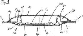
図1は車体板金1の開口に挿入された密封栓を示す。この栓はキャップ10と固定部20とからなる。ここに示す栓は円形で、特に図4の下面図に示すように回転対称となっている。 FIG. 1 shows a sealing plug inserted into an opening of a vehicle body sheet metal 1. This stopper consists of a cap 10 and a fixing part 20. The stopper shown here is circular, and in particular is rotationally symmetric as shown in the bottom view of FIG.
キャップ10と固定部20とは、環状帯30に沿って溶着されている。キャップ10には弾性的な周縁フランジ12が設けられ、第1の周縁ホットメルトシール部14が設けられている。キャップ10は、円筒壁18に隣接する環状底壁16と、円筒壁18の環状底壁16とは反対側の端にあって板金1に向かって外方へ延びるように構成されたフランジ12とを備える。
The cap 10 and the fixing part 20 are welded along the
固定部20には、環状接続面30の外側に第2フランジ22が設けられており、第2シール部24やホットメルトが設けられている。
The fixed portion 20 is provided with a
圧力補償壁40がキャップ10の内部、底壁16と固定部20との間にある。この圧力補償チャンバー40はキャップ10の基部16の一部から形成される上限壁44と、固定部20の中央部分から形成される下限壁44とによって上向きに固定されている。
A
空洞50は板金1と、シール部14および24と、固定部20の第1フランジ12および第2フランジ23によって形成される。この空洞50の体積は境界面の構成によって実質的に予め限定される。この空洞50は図1で省略されたダクトを通じて圧力補償チャンバー40と連通する。
The
圧力補償チャンバー40の上限壁42と下限壁44とは弾性的であり、その結果、空洞50内の温度変化によって生じる圧力変化は、この圧力補償チャンバー40の体積の変化によって自動的に補償される。
The
図示したように、圧力補償チャンバー40の下限壁44は上限壁42よりも薄い。両境界壁42と44との間のスペーサ62が、両境界壁の間の最小間隔、すなわち圧力補償チャンバー40の最小体積を予め決定するように形成されている。
As shown, the
また図にはキャップ10の円筒部分18に形成された芯だしリブ60が示されている。この芯だしリブ60には、開口への栓の挿入を容易にするため、下端部分64に傾斜が設けられている。さらに第2のフランジをシール部24とともに開口に挿入する際に問題が生じないようにするため、第2のフランジが芯だしリブ60の方向に向かって内側に十分に変形するように芯だしリブ60の寸法が選定されている。
The figure also shows centering
これら2つのフランジはそれぞれ板金1に向かって外側に延びている。いずれのフランジも弾性的で、挿入されると2つのシール部14および24が板金1に圧縮力を加える。
Each of these two flanges extends outward toward the sheet metal 1. Both flanges are elastic, and when inserted, the two
図1は2つのシール部14および24が低温状態で接着し密封を確実に行っている状態を示している。シール部14および24には、その全周縁において空気の介在や流入出するガスに起因する変形がない。
FIG. 1 shows a state in which the two
図1に示す低温状態では、2つの境界面42および44がこの温度での変形状態にあるため、圧力補償チャンバー40は最小の体積を有している。これらの境界面の変形は、圧力補償チャンバー40内および空洞50内の圧力が、外部雰囲気の圧力と同じになるように設計されている。
In the low temperature state shown in FIG. 1, the
図2は加熱前の同じ密封栓を示す。ホットメルトシール部14および24は未だに溶融しておらず、したがってそれぞれ初期の形状を維持している。圧力補償チャンバー40の境界壁42および44はそれぞれ外側に膨らみ、それぞれが緩和された形状になっている。圧力補償チャンバー40の体積は、図1に示された状態よりかなり大きくなっている。
FIG. 2 shows the same sealing plug before heating. The hot melt seals 14 and 24 are not yet melted, and therefore maintain their initial shapes. The
図2はまた、2つの弾性的なフランジ12および22がシール部14および24をそれぞれ板金1に押しつけていることを示している。このようにして栓は、予期せぬずれや開口からの脱落が起こらないようになっている。しかしながら溶融前のこの状態では、前記シール部は空洞50を密封していない。
FIG. 2 also shows that the two
図3は図1および図2の栓が開口に挿入される前の状態を示す。図3は図1および図2に相対して対称軸70の周りに回転された栓を示しており、芯だしリブは1つのみ見ることができる。
FIG. 3 shows a state before the stopper of FIGS. 1 and 2 is inserted into the opening. FIG. 3 shows the plug rotated about the axis of
図3には圧力補償チャンバー40を空洞50につなぐダクト66が示されている。
FIG. 3 shows a
また図3は2つのフランジが未変形の状態を示す。この状態では、(挿入された状態では板金1の上面に固定される)シール部14が、(挿入された状態では板金1の下方に構成される)シール部24の下方に位置している。その結果、挿入状態では2つのフランジが弾性的に変形し、それにより板金1に力を加えることは明らかである。フランジ12および22によって加えられる力は反対の方向を向き、これにより栓を自動的に所望の高さに配置する。
FIG. 3 shows a state in which the two flanges are not deformed. In this state, the seal portion 14 (fixed to the upper surface of the sheet metal 1 in the inserted state) is positioned below the seal portion 24 (configured below the sheet metal 1 in the inserted state). As a result, it is clear that in the inserted state, the two flanges are elastically deformed, thereby applying a force to the sheet metal 1. The force applied by the
再度、図3において、圧力補償チャンバー40の上限壁42と下限壁44とは、図2におけるものと同様、元の未変形の形状となっている。このように明らかに外側を向く形態において、上限壁42はスペーサ62からある距離をもって離れている。
Again, in FIG. 3, the
図4は下方から見た図で、栓が回転対称であることを示している。この図は最も外側のフランジ12と、第2周縁フランジのより内側の下面を示す。圧力補償チャンバー50の下限壁が中央の44として示されている。
FIG. 4 is a view from below, showing that the stopper is rotationally symmetric. This figure shows the
1 板金
10 キャップ
12 第1フランジ
14 第1シール部
16 基部壁
18 円筒部
20 固定部
22 第2フランジ
24 第2シール部
30 環状帯
40 圧力補償チャンバー
42 境界壁
44 境界壁
50 空洞
60 芯だしリブ
66 ダクト
DESCRIPTION OF SYMBOLS 1 Sheet metal 10
Claims (1)
前記開口部を覆うキャップ(10)であって、前記板金(1)または前記床の1つの側に固定される第1の周縁シール部(14)が設けられた周縁フランジ(12)を含むキャップ(10)と、
前記開口に入る固定部(20)と、
前記キャップ(10)または固定部(20)に形成された第2の周縁シール部(24)であって、前記第1のシール部(14)から離間し、前記板金(1)または前記床上に固定された第2の周縁シール部(24)とを備え、
前記板金(1)または前記床と、前記2つのシール部(14,24)と、前記栓の少なくとも1つの壁とが空洞(50)を形成し、
前記空洞(50)と連通する圧力補償チャンバー(40)を含み、前記圧力補償チャンバー(40)の体積を変えることによって、前記空洞(50)内部の温度変化によって生じる圧力変化を補償することを特徴とした栓。A plug that seals the opening in the sheet metal (1) or vehicle floor,
A cap (10) covering the opening, the cap (10) comprising a peripheral flange (12) provided with a first peripheral seal (14) fixed to the sheet metal (1) or one side of the floor (10) and
A fixing part (20) entering the opening;
A second peripheral seal portion (24) formed on the cap (10) or the fixing portion (20), which is separated from the first seal portion (14) and is placed on the sheet metal (1) or the floor; A fixed second peripheral seal (24);
The sheet metal (1) or the floor, the two sealing parts (14, 24) and at least one wall of the plug form a cavity (50);
A pressure compensation chamber (40) communicating with the cavity (50) is included, and a pressure change caused by a temperature change inside the cavity (50) is compensated by changing a volume of the pressure compensation chamber (40). A stopper.
Applications Claiming Priority (3)
| Application Number | Priority Date | Filing Date | Title |
|---|---|---|---|
| DE102006007914.0 | 2006-02-16 | ||
| DE102006007914A DE102006007914B4 (en) | 2006-02-16 | 2006-02-16 | Sealing plug with pressure compensation chamber |
| PCT/IB2007/000090 WO2007093862A1 (en) | 2006-02-16 | 2007-01-12 | A sealing plug with a pressure-compensating chamber |
Publications (3)
| Publication Number | Publication Date |
|---|---|
| JP2009526959A JP2009526959A (en) | 2009-07-23 |
| JP2009526959A5 JP2009526959A5 (en) | 2010-03-04 |
| JP4988771B2 true JP4988771B2 (en) | 2012-08-01 |
Family
ID=37909385
Family Applications (1)
| Application Number | Title | Priority Date | Filing Date |
|---|---|---|---|
| JP2008554865A Expired - Fee Related JP4988771B2 (en) | 2006-02-16 | 2007-01-12 | Seal plug with pressure compensation chamber |
Country Status (7)
| Country | Link |
|---|---|
| US (1) | US8070008B2 (en) |
| EP (1) | EP1984230B1 (en) |
| JP (1) | JP4988771B2 (en) |
| KR (1) | KR20080092958A (en) |
| CN (1) | CN101365619B (en) |
| DE (2) | DE102006007914B4 (en) |
| WO (1) | WO2007093862A1 (en) |
Families Citing this family (23)
| Publication number | Priority date | Publication date | Assignee | Title |
|---|---|---|---|---|
| DE102009018395B4 (en) * | 2009-04-22 | 2011-02-10 | Trw Automotive Electronics & Components Gmbh | sealing plug |
| DE102009057750A1 (en) | 2009-06-24 | 2010-12-30 | Illinois Tools Work Inc., Glenview | Device for insertion into a component opening of an automobile |
| DE102009032243A1 (en) | 2009-07-03 | 2011-01-05 | Illinois Tool Works Inc., Glenview | Sealing plug for closing opening of sheet metal of automobile, has two groups of ribs arranged over periphery of cylindrical section, where ribs of one group are connected with section and ribs of other group are connected with flange |
| DE202010005749U1 (en) * | 2010-04-19 | 2011-09-02 | Trw Automotive Electronics & Components Gmbh | sealing plug |
| US8672178B2 (en) * | 2010-04-20 | 2014-03-18 | Illinois Tool Works Inc. | Hole plug assembly |
| JP2012237381A (en) * | 2011-05-12 | 2012-12-06 | Nifco Inc | Hole plug |
| ES2415758B1 (en) * | 2011-06-20 | 2014-09-09 | Illinois Tool Works, Inc. | ORIFICE SHUTTER PLUG |
| JP5921353B2 (en) * | 2011-11-16 | 2016-05-24 | 株式会社ニフコ | Hole plug |
| US8833836B2 (en) | 2012-01-18 | 2014-09-16 | GM Global Technology Operations LLC | Tunable water deflector |
| JP5944279B2 (en) * | 2012-07-30 | 2016-07-05 | 株式会社ニフコ | Hole plug |
| JP6122336B2 (en) * | 2013-04-22 | 2017-04-26 | 大和化成工業株式会社 | Hole plug |
| DE102013112629A1 (en) * | 2013-11-15 | 2015-05-21 | Trw Automotive Electronics & Components Gmbh | sealing plug |
| DE102014108068A1 (en) * | 2014-06-06 | 2015-12-17 | Illinois Tool Works, Inc. | sealing plug |
| DE102015102169B4 (en) | 2015-02-16 | 2016-08-25 | Trw Automotive Electronics & Components Gmbh | sealing plug |
| FR3032947B1 (en) * | 2015-02-24 | 2020-02-21 | Itw Fastener Products Gmbh | SEALING PLUGS, ASSEMBLY AND METHOD FOR SEALING AN OPENING |
| FR3037306B1 (en) * | 2015-06-09 | 2018-07-27 | Peugeot Citroen Automobiles Sa | DEVICE FOR SEALING A DEFINED OPENING IN A FLOOR OF A VEHICLE, WITH A CAVITY OF HOUSING |
| DE102016205528A1 (en) * | 2016-04-04 | 2017-10-05 | Siemens Aktiengesellschaft | Pressure vessel with a housing body and a housing cover |
| CN106143645A (en) * | 2016-07-08 | 2016-11-23 | 天津瑞林迪金属制品有限公司 | A kind of automobile-used front floor blanking cover |
| EP3363715B1 (en) * | 2017-02-21 | 2020-03-25 | Newfrey LLC | Closing plug for closing an opening |
| JP2018138794A (en) * | 2017-02-24 | 2018-09-06 | 株式会社ニフコ | Hole plug |
| EP3747743B1 (en) * | 2019-06-05 | 2022-07-27 | Illinois Tool Works Inc. | Sealing plugs |
| KR20220023968A (en) * | 2019-06-26 | 2022-03-03 | 클린 캔틴 인코포레이티드 | Ventilation lids for insulated containers |
| CN114087360A (en) * | 2021-10-18 | 2022-02-25 | 东风汽车集团股份有限公司 | Plugging device and part |
Family Cites Families (16)
| Publication number | Priority date | Publication date | Assignee | Title |
|---|---|---|---|---|
| US3851794A (en) * | 1970-09-01 | 1974-12-03 | Itw Ateco Gmbh | An expansible holeplug with seal |
| FR2452650A1 (en) * | 1979-03-28 | 1980-10-24 | Itw De France | METHOD AND DEVICE FOR WATERPROOFING OF HOLES, OPERATIONS AND OPENINGS IN PANELS |
| DE3512582C3 (en) * | 1985-04-06 | 1997-03-13 | Itw Ateco Gmbh | Perforated plugs, in particular for sealing paint outlet holes in motor vehicle bodies |
| DE3713503C1 (en) * | 1987-04-22 | 1988-01-14 | United Carr Gmbh Trw | Plastic cover |
| DE3817896A1 (en) * | 1988-05-26 | 1989-12-07 | United Carr Gmbh Trw | PLASTIC LOCKING CAP, ESPECIALLY FOR CLOSING AN OPENING IN A VEHICLE BODY |
| DE3831433C2 (en) * | 1988-09-15 | 1994-06-23 | United Carr Gmbh Trw | Plastic cover |
| DE3917407A1 (en) * | 1989-05-29 | 1990-12-06 | United Carr Gmbh Trw | LOCKING CAP |
| US5040803A (en) * | 1990-04-23 | 1991-08-20 | Cieslik David R | Cavity sealing arrangement and method |
| FR2780953B1 (en) * | 1998-07-09 | 2000-09-29 | Itw De France | SHUTTER FOR AN OPENING MADE IN A SHEET |
| FR2805503B1 (en) * | 2000-02-28 | 2002-05-31 | Itw De France | SHUTTER FOR AN OPENING MADE IN A SHEET |
| DE10148493B4 (en) * | 2001-10-01 | 2004-12-09 | Itw Automotive Products Gmbh & Co. Kg | Sealing plug for sealing an opening in a sheet metal of a body or the floor panel of automobiles |
| ES2240676T3 (en) * | 2002-06-19 | 2005-10-16 | I.T.W. España, S.A. | OBTURATED SEALER OF HOLES. |
| DE10253983B4 (en) * | 2002-11-15 | 2007-01-11 | Itw Automotive Products Gmbh & Co. Kg | Closing plug for sealing and sound-absorbing closing of a hole in a component |
| DE10308669B4 (en) * | 2003-02-28 | 2006-06-08 | Daimlerchrysler Ag | Drainage arrangement for a body cavity |
| DE20304994U1 (en) * | 2003-03-27 | 2003-07-31 | TRW Automotive Electronics & Components GmbH & Co.KG, 67677 Enkenbach-Alsenborn | Blanking plug |
| JP4100291B2 (en) * | 2003-08-06 | 2008-06-11 | 日産自動車株式会社 | Automotive jack-up cover |
-
2006
- 2006-02-16 DE DE102006007914A patent/DE102006007914B4/en not_active Expired - Fee Related
-
2007
- 2007-01-12 US US12/279,047 patent/US8070008B2/en not_active Expired - Fee Related
- 2007-01-12 WO PCT/IB2007/000090 patent/WO2007093862A1/en active Application Filing
- 2007-01-12 JP JP2008554865A patent/JP4988771B2/en not_active Expired - Fee Related
- 2007-01-12 DE DE602007001675T patent/DE602007001675D1/en not_active Expired - Fee Related
- 2007-01-12 KR KR1020087019869A patent/KR20080092958A/en not_active Application Discontinuation
- 2007-01-12 CN CN2007800021097A patent/CN101365619B/en not_active Expired - Fee Related
- 2007-01-12 EP EP07705429A patent/EP1984230B1/en not_active Not-in-force
Also Published As
| Publication number | Publication date |
|---|---|
| WO2007093862A1 (en) | 2007-08-23 |
| JP2009526959A (en) | 2009-07-23 |
| US8070008B2 (en) | 2011-12-06 |
| DE602007001675D1 (en) | 2009-09-03 |
| DE102006007914A1 (en) | 2007-08-30 |
| CN101365619B (en) | 2010-07-28 |
| DE102006007914B4 (en) | 2008-02-28 |
| EP1984230B1 (en) | 2009-07-22 |
| US20090078704A1 (en) | 2009-03-26 |
| KR20080092958A (en) | 2008-10-16 |
| EP1984230A1 (en) | 2008-10-29 |
| CN101365619A (en) | 2009-02-11 |
Similar Documents
| Publication | Publication Date | Title |
|---|---|---|
| JP4988771B2 (en) | Seal plug with pressure compensation chamber | |
| JP5441920B2 (en) | Double-walled container with pressure compensation opening | |
| CN102803053B (en) | Device for inserting into an opening of a component on an automobile | |
| ES2773057T3 (en) | Fiber optic tanks | |
| US20060261531A1 (en) | Bush type hydraulic rubber mount and method of making same | |
| CN112352342B (en) | Secondary battery and method for manufacturing same | |
| JP6460781B2 (en) | Liquid filled vibration isolator | |
| JPWO2004051113A1 (en) | Liquid-filled vibration isolator | |
| CN110630679A (en) | Chamber for liquid compound spring | |
| US20240174301A1 (en) | Closure Device and Method for Closing Openings in Carrier Components | |
| JP6941603B2 (en) | Containers with stiffeners and methods for reinforcing containers | |
| CN110062729A (en) | Seal stopple | |
| JP4375246B2 (en) | Liquid seal vibration isolator with resin bracket | |
| JP2008175341A (en) | Pressure vessel and manufacturing method for pressure vessel | |
| JP6431437B2 (en) | Vibration isolator | |
| JP5937429B2 (en) | Method for manufacturing fuel tank cap | |
| JP5060196B2 (en) | Diaphragm | |
| ES2260883T3 (en) | CLOSING COVER. | |
| WO2016174801A1 (en) | Antivibration device | |
| JP6297371B2 (en) | Method for manufacturing fluid-filled vibration isolator | |
| JP5191950B2 (en) | Vibration isolator | |
| US20130319107A1 (en) | Flow meter having a housing with a separable closure | |
| JP2020138781A (en) | tank | |
| JP3736302B2 (en) | Method for manufacturing fluid-filled mounting device | |
| JP4069907B2 (en) | Liquid seal type vibration isolator with resin bracket |
Legal Events
| Date | Code | Title | Description |
|---|---|---|---|
| A521 | Request for written amendment filed |
Free format text: JAPANESE INTERMEDIATE CODE: A523 Effective date: 20100112 |
|
| A621 | Written request for application examination |
Free format text: JAPANESE INTERMEDIATE CODE: A621 Effective date: 20100112 |
|
| A977 | Report on retrieval |
Free format text: JAPANESE INTERMEDIATE CODE: A971007 Effective date: 20120224 |
|
| TRDD | Decision of grant or rejection written | ||
| A01 | Written decision to grant a patent or to grant a registration (utility model) |
Free format text: JAPANESE INTERMEDIATE CODE: A01 Effective date: 20120327 |
|
| A01 | Written decision to grant a patent or to grant a registration (utility model) |
Free format text: JAPANESE INTERMEDIATE CODE: A01 |
|
| A61 | First payment of annual fees (during grant procedure) |
Free format text: JAPANESE INTERMEDIATE CODE: A61 Effective date: 20120426 |
|
| R150 | Certificate of patent or registration of utility model |
Free format text: JAPANESE INTERMEDIATE CODE: R150 Ref document number: 4988771 Country of ref document: JP Free format text: JAPANESE INTERMEDIATE CODE: R150 |
|
| FPAY | Renewal fee payment (event date is renewal date of database) |
Free format text: PAYMENT UNTIL: 20150511 Year of fee payment: 3 |
|
| R250 | Receipt of annual fees |
Free format text: JAPANESE INTERMEDIATE CODE: R250 |
|
| R250 | Receipt of annual fees |
Free format text: JAPANESE INTERMEDIATE CODE: R250 |
|
| R250 | Receipt of annual fees |
Free format text: JAPANESE INTERMEDIATE CODE: R250 |
|
| R250 | Receipt of annual fees |
Free format text: JAPANESE INTERMEDIATE CODE: R250 |
|
| R250 | Receipt of annual fees |
Free format text: JAPANESE INTERMEDIATE CODE: R250 |
|
| LAPS | Cancellation because of no payment of annual fees |