JP4375246B2 - Liquid seal vibration isolator with resin bracket - Google Patents
Liquid seal vibration isolator with resin bracket Download PDFInfo
- Publication number
- JP4375246B2 JP4375246B2 JP2005034851A JP2005034851A JP4375246B2 JP 4375246 B2 JP4375246 B2 JP 4375246B2 JP 2005034851 A JP2005034851 A JP 2005034851A JP 2005034851 A JP2005034851 A JP 2005034851A JP 4375246 B2 JP4375246 B2 JP 4375246B2
- Authority
- JP
- Japan
- Prior art keywords
- caulking
- resin bracket
- metal fitting
- liquid chamber
- cylindrical
- Prior art date
- Legal status (The legal status is an assumption and is not a legal conclusion. Google has not performed a legal analysis and makes no representation as to the accuracy of the status listed.)
- Expired - Fee Related
Links
Images


Description
この発明は防振装置に関し、詳しくは樹脂ブラケット付きの液封防振装置に関する。 The present invention relates to a vibration isolator, and more particularly to a liquid seal vibration isolator with a resin bracket.
近年、車両の軽量化のニーズの高まりによって、エンジンを防振支持する防振マウントその他の防振装置に対しても軽量化のニーズが高まっている。
この場合、防振装置におけるブラケットを樹脂化することが軽量化のための有効な手段である。
2. Description of the Related Art In recent years, with an increasing need for weight reduction of vehicles, there is an increasing need for weight reduction for vibration isolation mounts and other vibration isolation devices that support the vibration isolation of engines.
In this case, making the bracket in the vibration isolator resin is an effective means for reducing the weight.
ところで、防振装置の一種として液室内部に液を封入し、その液の流動に基づいて振動減衰を行うようになした液封式の防振装置が用いられている。
そしてこの液封防振装置におけるブラケットを樹脂化して、次のような構成とした樹脂ブラケット付き液封防振装置、即ち(a)支持部材及び被支持部材の一方に取付固定される剛性の取付部材と、(b)他方に取付固定される樹脂ブラケットと、(c)取付部材と樹脂ブラケットとを弾性連結する本体ゴム部と、(d)筒形をなして内側に液室を形成し、液室の軸方向の一方を本体ゴム部で閉鎖させる状態に本体ゴム部と樹脂ブラケットとを連結する筒形金具と、(e)液室の軸方向の他方を閉鎖する、ゴム製のダイヤフラムを備えた蓋体と、(f)液室内に組み込まれて液室を第1液室と第2液室とに区画する仕切部材と、(g)第1液室と第2液室とを連通させるオリフィス通路と、を備えて成る樹脂ブラケット付き液封防振装置が、従来公知である。
By the way, as a kind of vibration isolator, a liquid seal type vibration isolator is used in which a liquid is sealed in a liquid chamber and vibration is attenuated based on the flow of the liquid.
Then, the bracket in this liquid seal vibration isolator is made of resin, and the liquid seal vibration isolator with resin bracket having the following configuration, that is, (a) a rigid attachment that is attached and fixed to one of the supporting member and the supported member A member, (b) a resin bracket that is attached and fixed to the other, (c) a main rubber portion that elastically connects the attachment member and the resin bracket, and (d) a liquid chamber is formed on the inside by forming a cylindrical shape, A cylindrical metal fitting that connects the main rubber part and the resin bracket in a state where one of the liquid chambers in the axial direction is closed by the main body rubber part, and (e) a rubber diaphragm that closes the other of the liquid chambers in the axial direction. A lid provided, (f) a partition member that is incorporated in the liquid chamber and divides the liquid chamber into a first liquid chamber and a second liquid chamber, and (g) communicates the first liquid chamber and the second liquid chamber. A liquid seal vibration isolator with a resin bracket comprising an orifice passage to be made is conventionally known.
下記特許文献1に、この種樹脂ブラケット付き液封防振装置の一例が開示されている。
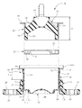
図12はその具体例を示している。
同図において200は支持部材及び被支持部材の一方に取付固定される剛性の取付部材で、202は本体ゴム部、204は樹脂ブラケット、206,208はそれぞれ第1液室,第2液室で、210はそれらを区画する仕切部材である。
FIG. 12 shows a specific example thereof.
In the figure, 200 is a rigid mounting member that is fixedly attached to one of the supporting member and the supported member, 202 is a main rubber part, 204 is a resin bracket, and 206 and 208 are a first liquid chamber and a second liquid chamber, respectively. , 210 is a partition member for partitioning them.
この仕切部材210には、第1液室206と第2液室208とを連通させる環状のオリフィス通路212が形成されている。
214はゴム製のダイヤフラム216と金属製の剛性の蓋板218を含む蓋体で、筒形金具220の内部に形成された液室の軸方向の一方がこの蓋体214で閉鎖されている。
尚液室の軸方向の今一方の側は本体ゴム部202にて閉鎖されている。
215は、ダイヤフラム216の外側に形成された空気室である。
An
The other side of the liquid chamber in the axial direction is closed by the
筒形金具220は、樹脂ブラケット204から軸方向に僅かに突出させられていて、その突出部が蓋体214における金属製の蓋板218の外周部にかしめ付けられている。図中222はそのかしめ部を表わしている。
即ちこの図12に示す樹脂ブラケット付き液封防振装置は、本体ゴム部202と取付部材200との一体加硫品から成るマウント本体に対して、樹脂ブラケット204が一体に成形されて予備組付品とされ、これに対して蓋体214がかしめ付けにより組み付けられて、樹脂ブラケット付き液封防振装置が構成されている。
The
That is, in the liquid seal vibration isolator with a resin bracket shown in FIG. 12, the
下記特許文献2には、この種樹脂ブラケット付き液封防振装置において、マウント本体に対して樹脂ブラケットを成形するための方法が開示されている。
図13はその具体例を示している。
同図において、224は樹脂ブラケット204の成形用の金型で、図示のようにここでは本体ゴム部202と、取付部材200と、筒形金具220との一体加硫品から成るマウント本体を金型224にセットしておき、そして金型224に形成されたキャビティ226に樹脂材料を充填して、樹脂ブラケット204をマウント本体に一体に成形する。
図12の蓋体214は、このようにして得られた予備組付品に対して後工程でかしめ付けられ、図12に示す樹脂ブラケット付き液封防振装置を構成する。
FIG. 13 shows a specific example thereof.
In the figure,
The
ところで、このように本体ゴム部202を有するマウント本体に対して樹脂ブラケット204を成形一体化すると、次のような問題が生ずる。
金型224のキャビティ226に樹脂材料を所定の圧力で注入し、樹脂ブラケット204を成形する際、その圧力で本体ゴム部202に対し、これを弾性変形させる力が作用する。
従ってその際の圧力によって本体ゴム部202が変形を生じないように、金型224を本体ゴム部202に接触させておいて、本体ゴム部202にかかる圧力を金型224に受けるようにしておくことが必要となる。
By the way, when the
When a resin material is injected into the
Accordingly, the
しかしながら本体ゴム部202の形状は、車両性能即ち防振装置に求められる防振性能に応じてさまざまに異なった形状となり、従って本体ゴム部202を有するマウント本体に対して樹脂ブラケット204を後成形で一体化するようになした場合、樹脂ブラケット204成形のための金型224がそれ専用の金型となり、本体ゴム部202の形状が異なるごとに、それぞれ専用の金型224が必要となってしまい、そのことによって防振装置の製造コストが高いものとなってしまう。
However, the shape of the main
図12に示す防振装置にはまた、次のような問題も内在する。
図12に示す防振装置の場合、かしめ加工前の筒形金具220の先端部、即ち軸方向に環状に起立した状態にあるかしめ部220を、径方向内向きに曲げるかしめ加工を行う際、筒形金具220自体でその際のかしめ力を受けることができず、そのかしめ力を樹脂ブラケット204にて受けざるを得ない。
この場合、かしめ力の作用によって樹脂ブラケット204に大きな歪みが発生し、かしめ力を受ける受具と樹脂ブラケット204との形態が不適合である場合に、樹脂ブラケット204に亀裂が生じ或いは割れを生じる恐れがある。
The vibration isolator shown in FIG. 12 also has the following problems.
In the case of the vibration isolator shown in FIG. 12, when the caulking process is performed to bend the
In this case, the
本発明は以上のような事情背景とし、製造コストを安価となし得る樹脂ブラケット付き液封防振装置を提供することを目的としてなされたものである。
また本発明の他の目的は、かしめ加工によって樹脂ブラケット付き液封防振装置を組み付け一体化するに際し、樹脂ブラケットに亀裂や割れが生じる問題を解決することを目的とする。
The present invention has been made for the purpose of providing a liquid seal vibration isolator with a resin bracket that can be manufactured at a low manufacturing cost.
Another object of the present invention is to solve the problem of cracks and cracks in the resin bracket when the liquid seal vibration isolator with resin bracket is assembled and integrated by caulking.
而して請求項1のものは、(a)支持部材及び被支持部材の一方に取付固定される剛性の取付部材と、(b)他方に取付固定される樹脂ブラケットと、(c)前記取付部材と該樹脂ブラケットとを弾性連結する本体ゴム部と、(d)筒形をなして内側に液室を形成し、該液室の軸方向の一方を該本体ゴム部で閉鎖させる状態に該本体ゴム部と該樹脂ブラケットとを連結する筒形金具と、(e)該液室の軸方向の他方を閉鎖する、ゴム製のダイヤフラムを備えた蓋体と、(f)該液室内に組み込まれて該液室を第1液室と第2液室とに区画する仕切部材と、(g)該第1液室と第2液室とを連通させるオリフィス通路と、を備えて成る樹脂ブラケット付き液封防振装置において、前記蓋体は、前記ダイヤフラムの外周部に沿って環状をなす金具部を有するものとなして、該金具部に対し該ダイヤフラムを一体に加硫接着し、更に該蓋体に対して、先端部にかしめ部を有する前記筒形金具を一体に加硫接着して、該蓋体と該筒形金具とを一体加硫品となし、該一体加硫品に対し前記樹脂ブラケットを一体成形して予備組付品となし、該予備組付品は、(イ)前記筒形金具が、前記樹脂ブラケットから軸方向に所定高さ突出して突出側の先端部且つ前記樹脂ブラケットとの間にかしめ加工の際のかしめ力を受ける受具の挿入空間を形成する位置において径方向外向きのフランジ部を有する形態、及び(ロ)前記金具部が、前記かしめ部とは反対側の下面を所定幅に亘って露出させ且つ露出部を前記かしめ加工の際に支持治具にて支持される平坦な支持面として有する形態、のうちの少なくとも一方の形態をなすものとして、前記本体ゴム部と前記取付部材の一体加硫品から成るマウント本体と該予備組付品とを互いに組み付けて構成したことを特徴とする。
Thus to those of
請求項2のものは、請求項1において、前記筒形金具が前記フランジ部を有するものとなしてあって、該フランジ部に続いて前記かしめ部が設けられており、また前記マウント本体の外周部にはかしめ固定用の金具が設けられていて、該かしめ固定用の金具に対し前記筒形金具のかしめ部がかしめ付けられることで、前記予備組付品とマウント本体とが一体に組み付けられていることを特徴とする。
Of those
請求項3のものは、請求項2において、前記かしめ固定用の金具はスリーブを成していて、前記本体ゴム部に一体加硫接着されており、前記かしめ部側の軸方向端部が径方向外向きのフランジ部をなしていて、該フランジ部に対して前記筒形金具のかしめ部がかしめ付けられていることを特徴とする。 According to a third aspect of the present invention, in the second aspect, the caulking fixing metal fitting forms a sleeve, is integrally vulcanized and bonded to the main body rubber portion, and an axial end portion on the caulking portion side has a diameter. A flange portion that is outward in the direction is formed, and a caulking portion of the cylindrical metal fitting is caulked to the flange portion.
請求項4のものは、請求項3において、前記スリーブをなす前記かしめ固定用の金具は前記筒形金具の内面に沿って軸方向に延びており、前記かしめ部とは反対側の端部において前記仕切部材を押圧していることを特徴とする。 According to a fourth aspect of the present invention, in the third aspect, the caulking fixing metal fitting forming the sleeve extends in the axial direction along the inner surface of the cylindrical metal fitting, and at an end opposite to the caulking portion. The partition member is pressed.
以上のように本発明は、本体ゴム部を有するマウント本体に対して樹脂ブラケットを一体成形して予備組付品となすのではなく、蓋体と筒形金具との一体加硫品に対して樹脂ブラケットを一体成形して予備組付品となし、本体ゴム部と取付部材の一体加硫品からなるマウント本体を、この予備組付品に組み付けて樹脂ブラケット付き液封防振装置を構成するようになしたものである。 As described above, the present invention does not form a resin bracket integrally with a mount body having a main body rubber portion to form a pre-assembled product, but instead of an integrated vulcanized product of a lid and a cylindrical metal fitting. A resin bracket is integrally molded to form a pre-assembled product, and a mount body made of an integrated vulcanized product of the main body rubber part and mounting member is assembled to this pre-assembled product to constitute a liquid seal vibration isolator with a resin bracket. It was made like that.
かかる本発明は、本体ゴム部の形状については車両性能の相異即ち防振装置に求められる防振性能の相異に応じてさまざまに変化する一方で、液封防振装置における蓋体については求められる防振性能が相異しても、多くは共通して用い得る点に着目してなされたものである。
より詳しくは、本体ゴム部の形状が類似した形状のものであれば、蓋体として同じものを使うことができる(本体ゴム部側に樹脂ブラケットを成形する場合には、本体ゴム部の形状が僅かに異なっても別の専用の成形用の金型を必要とする)点に着目したものである。
In the present invention, the shape of the main rubber part varies depending on the difference in vehicle performance, that is, the difference in the vibration-proof performance required for the vibration-proof device. Even if the required anti-vibration performance is different, many have been made paying attention to the fact that they can be used in common.
More specifically, as long as the shape of the main rubber portion is similar, the same lid can be used (when the resin bracket is molded on the main rubber portion side, the shape of the main rubber portion is This requires attention to the point that a separate molding die is required even if it is slightly different.
かかる本発明によれば、車両性能の相異によって本体ゴム部の形状が様々に異なっても、樹脂ブラケット成形のための金型を共通化でき、これにより樹脂ブラケット付き液封防振装置の製造コストを安価となすことができる。 According to the present invention, even when the shape of the main rubber part varies depending on the vehicle performance, the mold for molding the resin bracket can be made common, thereby manufacturing the liquid seal vibration isolator with the resin bracket. Cost can be reduced.
本発明では、蓋体側の筒形金具を樹脂ブラケットから軸方向に突出させて、その突出側の先端部且つ樹脂ブラケットとの間にかしめ力を受ける受具の挿入空間を形成する位置において径方向外向きのフランジ部を設けておくことができ、このようになしておくことで筒形金具のかしめ部をマウント本体にかしめ付けるに際し、フランジ部と樹脂ブラケットとの間の挿入空間にかしめ装置の受具を挿入して、筒形金具自体且つフランジ部においてかしめ装置によるかしめ力を受けるようになすことができる。
また蓋体に備えた環状をなす金具部に平坦な支持面を形成しておくことができ、このようになしておくことでかしめ加工の際に支持治具にてその平坦な支持面を支持することができる。 In the present invention, the cylindrical metal fitting on the lid side is protruded in the axial direction from the resin bracket, and the radial direction is formed at the position where the insertion space of the receiving device receiving the caulking force is formed between the protruding end and the resin bracket. You can leave provided a flange portion outward, when crimped caulking portion of the cylindrical metal member by leave without thus mount the body, crimping device into the insertion space between the flange portion and the resin bracket Thus, it is possible to receive the caulking force from the caulking device at the cylindrical metal fitting itself and at the flange portion.
In addition, a flat support surface can be formed on the ring-shaped metal fitting provided on the lid, and by doing so, the flat support surface is supported by a support jig during caulking. can do.
従ってこの本発明の液封防振装置では、かしめ加工の際のかしめ力が樹脂ブラケットに作用して、樹脂ブラケットに大きな歪みが発生し、その歪みによって樹脂ブラケットに亀裂が発生したり割れが生じたりするのを良好に防止することができる。 Therefore, in this liquid seal vibration isolator of the present invention , the caulking force at the time of caulking processing acts on the resin bracket, and a large distortion occurs in the resin bracket. Can be prevented well.
本発明では、マウント本体の外周部にかしめ固定用の金具を設けておき、そのかしめ固定用の金具に対し、筒形金具のフランジ部に続いて設けたかしめ部をかしめ付けるようになしておくことができる(請求項2)。In the present invention, a caulking fixing metal fitting is provided on the outer peripheral portion of the mount main body, and the caulking portion provided subsequent to the flange portion of the cylindrical metal fitting is caulked to the caulking fixing metal fitting. (Claim 2).
この場合において、本体ゴム部にスリーブ金具を一体加硫接着してこれをかしめ固定用の金具となし、そしてそのスリーブ金具の軸方向端部を径方向外向きのフランジ部となして、これに対し上記筒形金具のかしめ部をかしめ付けるようになすことができる(請求項3)。 In this case, the sleeve metal fitting is integrally vulcanized and bonded to the main rubber part to form a metal fitting for caulking, and the axial end of the sleeve metal fitting serves as a radially outward flange. On the other hand, the caulking portion of the cylindrical metal fitting can be caulked (claim 3).
更にこの場合において、そのスリーブ金具を上記筒形金具の内面に沿って軸方向に延出させ、かしめ部とは反対側の端部において上記仕切部材を押圧するものとなしておくことができる(請求項4)。
このようにしておけば、本体ゴム部の弾性変形に伴なって仕切部材が液室内で位置移動してしまうのを良好に防止できる。
Furthermore, in this case, the sleeve fitting can be extended in the axial direction along the inner surface of the cylindrical fitting, and the partition member can be pressed at the end opposite to the caulking portion ( Claim 4).
By doing so, it is possible to satisfactorily prevent the partition member from moving in the liquid chamber due to the elastic deformation of the main rubber part.
次に本発明の実施形態を図面に基づいて詳しく説明する。
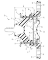
図1において、10はエンジンマウント等として用いられる本実施形態の樹脂ブラケット付き液封防振装置(以下単に液封防振装置とする)で、支持部材及び被支持部材の一方に取付固定される取付金具12と、他方に固定される樹脂ブラケット14と、取付金具12と樹脂ブラケット14とを弾性連結する本体ゴム部18と、筒形をなして内側に液室を形成し、液室の軸方向の一方を本体ゴム部18で閉鎖させる状態に本体ゴム部18と樹脂ブラケット14とを連結する筒形金具16と、液室の軸方向の他方を閉鎖する、ゴム製のダイヤフラム20を備えた蓋体22と、液室内に組み込まれてその液室を第1液室24と第2液室26とに区画する剛性の仕切部材28とを有している。
ここで仕切部材28には略環状のオリフィス通路30が形成されている。
このオリフィス通路30は、開口32において第1液室24と連通し、開口34において第2液室26と連通している。
Next, embodiments of the present invention will be described in detail with reference to the drawings.
In FIG. 1, 10 is a liquid seal vibration isolator with a resin bracket (hereinafter simply referred to as a liquid seal vibration isolator) of this embodiment used as an engine mount or the like, and is attached and fixed to one of a support member and a supported member. The mounting
Here, a substantially
The
この液封防振装置10では、第1液室24と第2液室26とに封入された液がオリフィス通路30を通じて一方から他方に、また他方から一方に移動し、その液の流動に基づいて振動減衰作用をなす。
ここで本体ゴム部18は、図中下向きに断面ハの字状に拡開したゴム脚36を有しており、そのゴム脚36の内側(下側)に第1液室24を形成している。
また樹脂ブラケット14には、固定孔38を有する金具40が一体に固着されている。
In this liquid
Here, the main
A
図2及び図3は液封防振装置10を組み付ける前の状態を表わしており、同図に示しているようにこの液封防振装置10は、本体ゴム部18を有する一体加硫品のマウント本体42と、樹脂ブラケット14を有する予備組付品44とを、仕切部材28とともにかしめ付けにより一体に組み付けて構成してある。
尚通常はこの組付けは液中で行い、その組付けによって液室内部に液を封入した状態とする。
但し組付後において液室内に液を封入することも可能である。
2 and 3 show a state before the liquid
Normally, this assembly is performed in a liquid, and the liquid is sealed in the liquid chamber by the assembly.
However, it is also possible to enclose the liquid in the liquid chamber after assembly.
マウント本体42は、かしめ固定用の金具としてのスリーブ金具46を外周部に有しており、そのスリーブ金具46に対し本体ゴム部18の外周面が一体に加硫接着してある。
スリーブ金具46の上端部には、径方向外向きのフランジ部48が形成されており、後述のようにこのフランジ部48に対し筒形金具16のかしめ部60がかしめ付け固定される。
尚本体ゴム部18は、スリーブ金具46の内面に沿って図中下向きに延びる円筒形状のゴム周壁50を有している。
The mount
A radially
The
予備組付品44は、蓋体22及び筒形金具16に対して樹脂ブラケット14を一体成形したものである。
ここで樹脂ブラケット14は、筒形金具16の下部を取り巻く円筒部52と、その下端から直角に折れ曲がった平板状の固定部54とを有している。
The
Here, the
蓋体22は、ダイヤフラム20の外周部に沿ってドーナツ環状をなす金具部56を有しており、この金具部56に対してダイヤフラム20が一体に加硫接着されている。
ここで金具部56は、筒形金具16と一体に構成されている。
この金具部56は、所定幅L1(L1は5mm以上が好ましい)に亘って下面が露出せしめられている。
この露出面は、かしめ加工の際に支持治具にて支持される平坦な支持面57を成している。
The
Here, the
The lower surface of the
This exposed surface forms a
筒形金具16は、樹脂ブラケット14から図中上向きに所定高さL2突き出しており(L2は15〜20mm程度が望ましい)、そしてその突出し側の端部即ち上端部において径方向外方向きのフランジ部58が設けられており、更にこのフランジ部58に続いて、かしめ部60が設けられている。
ここでかしめ部60は、かしめ前において図2に示すように軸方向、即ち図中上方に起立した形状の環状の立上り部60Aをなしている。
このフランジ部58と樹脂ブラケット14の図中上端との間は、かしめ加工の際のかしめ力を受ける受具の挿入空間を形成する。
Here, the
Between this
この筒形金具16の下部の外周面及び上記蓋体22における金具部56の外周部にはゴム膜62が一体に加硫接着されており、筒形金具16及び金具部56の外周部がゴム膜62を介して樹脂ブラケット14に固着されている。
即ち筒形金具16及びドーナツ環状の金具部56と樹脂ブラケット14との接触部にはゴム膜62が介在せしめられている。
A
That is, the
筒形金具16にはまた、その内周側にもゴム膜64が一体に加硫接着されている。
ここで内周側のゴム膜64は、筒形金具16の軸方向全長に亘って、詳しくはフランジ部58より下側の部分の内周面全面を被覆する状態で設けられている。
この内周側のゴム膜64はダイヤフラム20と一体成形されている。
筒形金具16の上端近傍位置には段違部66が形成されていて、この段違部66より上側の部分が大径部68とされており、ゴム膜64における大径部68の内側の部分が部分的に厚い厚肉部70とされている。このような厚肉部70を設けているのは図1のかしめ部60近傍でゴム膜64のゴムボリュームを多くすることによって確実なシールを確保するためである。
A
Here, the
The inner
A stepped
本実施形態の液封防振装置10は、予備組付品44とマウント本体42とをかしめ加工によって仕切部材28とともに一体に組み付けて構成する。
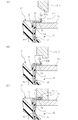
図4,図5にこのかしめ加工の工程が示してある。
このかしめ加工では、図4に示しているように蓋体22に設けられた支持面57を支持治具69にて支持するとともに、筒形金具16におけるフランジ部58と樹脂ブラケット14との間に形成されている挿入空間Kにかしめ装置の受具71を挿入し、その受具71によってフランジ部58を図中下側から受けるようにする。
そしてその状態で、図5(II)に示しているようにかしめ装置における第1かしめ具72-1にて環状の立上り部60Aを先ず一旦斜めに曲げ加工する。
The liquid
4 and 5 show the caulking process.
In this caulking process, as shown in FIG. 4, the
Then, in this state, as shown in FIG. 5 (II), the annular rising
続いて図5(III)に示しているように、同じく受具71にてフランジ部58を図中下側から受けた状態で、別の第2かしめ具72-2にて傾斜部60Bを水平に倒し、フランジ部58とともにかしめ部60にて、マウント本体42のスリーブ金具46のフランジ部48を軸方向に挟み込んだ状態とする。
ここにおいて筒形金具16の先端部のかしめ加工が終了し、これによりマウント本体42と予備組付品44とがかしめ固定され構造的に一体化された状態となる(図5(IV))。
Subsequently, as shown in FIG. 5 (III), the
Here, the caulking process of the tip end portion of the cylindrical metal fitting 16 is completed, and the mount
図6は樹脂ブラケット14の成形方法を、成形用の金型とともに示している。
図中72は樹脂ブラケット14の成形用の金型で、上型72Aと、中型72Bと、下型72Cとを有している。
この金型72にはキャビティ73が形成されており、そこに樹脂材料を注入し固化させることで、樹脂ブラケット14が成形される。
具体的には金型72に蓋体22,筒形金具16及び固定孔38を備えた金具40をセットしておき、そしてキャビティ73に樹脂材料を注入し成形することで、樹脂ブラケット14を蓋体22及び筒形金具16に対し成形一体化する。ここにおいて図2に示す予備組付品44が得られる。
尚上型72Aは、筒形金具16の内部に嵌入する凸型部74を有している。
この凸型部74は筒形金具16の下端にまでは達しておらず、その下側には空間76が生じている。
FIG. 6 shows a molding method of the
In the figure,
A
Specifically, the
The upper die 72 </ b> A has a
The
以上のような本実施形態によれば、車両性能の相異によって本体ゴム部18の形状が異なっても、蓋体22に対して樹脂ブラケット14を一体成形してなる予備組付品44を共通に用いることが可能であるため、樹脂ブラケット14成形のための金型72を共通に用いることが可能であり、これにより樹脂ブラケット付き液封防振装置10の製造コストを安価となすことができる。
According to the present embodiment as described above, even if the shape of the
また筒形金具16のかしめ部60を、マウント本体42にかしめ付けるに際し、フランジ部48と樹脂ブラケット14との間の挿入空間Kにかしめ装置の受具71を挿入して、筒形金具16自体且つフランジ部48においてかしめ装置によるかしめ力を受けることができ、従ってかしめ加工の際のかしめ力が樹脂ブラケット14に作用して、樹脂ブラケット14に大きな歪みが発生し、その歪みによって樹脂ブラケット14に亀裂が発生したり、割れが生じたりするのを良好に防止することができる。
Further, when the
更に本体ゴム部18のスリーブ金具46をかしめ固定用の金具となして、そのスリーブ金具46の図中下端部で仕切部材28を押圧するようになしているため、本体ゴム部18の弾性変形に伴なって仕切部材28が液室内で位置移動してしまうのを良好に防止することができる。
Further, the sleeve metal fitting 46 of the
図7は本発明の他の実施形態を示している。
この実施形態では、マウント本体42における本体ゴム部18の高さH2が上記実施形態の本体ゴム部42の高さH1に較べて僅かに高いものであるが、他の点については上記実施形態と同様である。
つまりダイヤフラム20を有する蓋体22,筒形金具16,樹脂ブラケット14が何れも共通、即ちそれらを組み付けて成る予備組付品44が上記実施形態と共通である。
FIG. 7 shows another embodiment of the present invention.
In this embodiment, the height of H 2 the
That is, the
従来の樹脂ブラケット付き液封防振装置では、ダイヤフラム20を有する蓋体22及び樹脂ブラケット14が同じ形状であるにも拘わらず、成形用の金型として上記実施形態の樹脂ブラケット14の成形用の金型とは別種の金型が必要であったが、本実施形態によれば樹脂ブラケット14の成形用の金型として共通の金型を用いることができる。
In the conventional liquid seal vibration isolator with a resin bracket, the
図8〜図10は本発明の更に他の実施形態を示している。
この実施形態では、図8に示しているように本体ゴム部18の内部に第3液室77と第4液室78とが形成され、それらがオリフィス金具80に形成されたオリフィス通路82にて互いに連通させられている。
ここでオリフィス通路82は、図10に示す開口84を通じて第3液室77と連通し、また図10の開口86を通じて第4液室78と連通している。
8 to 10 show still another embodiment of the present invention.
In this embodiment, as shown in FIG. 8, a third
Here, the
この実施形態では、取付金具12が相対的に図中右方向に移動すると、第3液室77内部の液がオリフィス通路82を通じて第4液室78へと流入し、また逆方向に相対移動すると第4液室78内の液がオリフィス通路82を通じて第3液室77へと流入し、その際の流動に基づいて図8中左右方向の振動減衰作用をなす。
ここで第3液室77から第4液室78への液の移動は、図10の開口84からオリフィス通路82内に流入した第3液室77の液が、オリフィス通路82における周方向通路82Aを図10中左向きに流動した後、図10(C)の折返し通路82Bを経て周方向通路82Cに至り、更に周方向通路82Cを図10(C)中右向きに流れて、図10(B)の周方向通路82Dから開口86を通じ第4液室78内に流入する。
尚逆方向の流れは上記とは逆向きとなる。
In this embodiment, when the mounting
Here, the movement of the liquid from the third
The reverse flow is in the opposite direction.
尚オリフィス金具80は本体ゴム部18とは別体をなしており、また本体ゴム部18の上端部には環状のかしめ固定用の環状の金具90が径方向外向きにフランジ状に突き出しており、そのかしめ固定用の金具90に対し、筒形金具16のかしめ部60がかしめつけられている。
また本体ゴム部18の下端部且つ外周部には、別の円筒状の金具92が、かしめ固定用の金具90と同様に一体加硫接着されており、この円筒状の金具92が、筒形金具16の内周面のゴム膜64を介して筒形金具16の内周面に当接し、更にまたその下端が仕切部材28に当接させられている。
The orifice fitting 80 is separate from the
Further, another cylindrical metal fitting 92 is integrally vulcanized and bonded to the lower end portion and the outer peripheral portion of the
この実施形態においても、上記実施形態における予備組付品44が共通に用いられている。
従ってこの実施形態においても、本体ゴム部18の形状が上記実施形態の形状とは異なっているにも拘わらず、樹脂ブラケット14成形用の金型として共通の金型を用いることができる。
尚、上記実施形態では筒形金具16の下部且つ外周面を被覆するゴム膜62が、樹脂ブラケット14の円筒部52の上端と同じ高さとされているが、図11に示しているようにこのゴム膜62の図中上端を、樹脂ブラケット14における円筒部52の図中上端よりも上向きに突出させておくことができる。
Also in this embodiment, the
Therefore, in this embodiment as well, a common mold can be used as a mold for molding the
In the above embodiment, the
例えばゴム膜62の上端と樹脂ブラケット14の円筒部52の上端とが同じ高さ即ち同じ位置であると、図6の中型72Bと筒形金具16との間に隙間が生じているとき(通常は若干の隙間が生じる)、樹脂ブラケット14の成形時にその隙間内に樹脂材料がはみ出して樹脂バリを生じ、その後樹脂バリが剥れたりすることによって、そこから水が浸入する恐れが生じる。
しかるにゴム膜62を樹脂ブラケットの円筒部52より突き出すようにしておけば、図11(B)に示しているように金型72における中型72Bを、ゴム膜62の突き出した部分に押圧状態となして、そこに隙間が生じないようにでき、従ってキャビティ73内に樹脂材料を注入したときに樹脂の一部がその隙間に入り込んで樹脂バリとなって残ってしまう問題を解消することができる。
従って後においてその樹脂バリが剥れる等して、そこから水が浸入する恐れが生じるのを確実に無くすことができる。
For example, when the upper end of the
However, if the
Therefore, it is possible to reliably eliminate the possibility that the resin burr will peel off later and water may enter from there.
以上本発明の実施形態を詳述したが、これらはあくまで一例示であり、本発明はその趣旨を逸脱しない範囲において種々変更を加えた形態で構成可能である。 Although the embodiments of the present invention have been described in detail above, these are merely examples, and the present invention can be configured in various modifications without departing from the spirit of the present invention.
10 液封防振装置
12 取付金具
14 樹脂ブラケット
16 筒形金具
18 本体ゴム部
20 ダイヤフラム
22 蓋体
24 第1液室
26 第2液室
28 仕切部材
30 オリフィス通路
42 マウント本体
44 予備組付品
46 スリーブ金具
48 フランジ部
60 かしめ部
71 受具
DESCRIPTION OF
Claims (4)
(b)他方に取付固定される樹脂ブラケットと、
(c)前記取付部材と該樹脂ブラケットとを弾性連結する本体ゴム部と、
(d)筒形をなして内側に液室を形成し、該液室の軸方向の一方を該本体ゴム部で閉鎖させる状態に該本体ゴム部と該樹脂ブラケットとを連結する筒形金具と、
(e)該液室の軸方向の他方を閉鎖する、ゴム製のダイヤフラムを備えた蓋体と、
(f)該液室内に組み込まれて該液室を第1液室と第2液室とに区画する仕切部材と、
(g)該第1液室と第2液室とを連通させるオリフィス通路と、
を備えて成る樹脂ブラケット付き液封防振装置において、
前記蓋体は、前記ダイヤフラムの外周部に沿って環状をなす金具部を有するものとなして、該金具部に対し該ダイヤフラムを一体に加硫接着し、更に該蓋体に対して、先端部にかしめ部を有する前記筒形金具を一体に加硫接着して、該蓋体と該筒形金具とを一体加硫品となし、該一体加硫品に対し前記樹脂ブラケットを一体成形して予備組付品となし、
該予備組付品は、(イ)前記筒形金具が、前記樹脂ブラケットから軸方向に所定高さ突出して突出側の先端部且つ前記樹脂ブラケットとの間にかしめ加工の際のかしめ力を受ける受具の挿入空間を形成する位置において径方向外向きのフランジ部を有する形態、及び(ロ)前記金具部が、前記かしめ部とは反対側の下面を所定幅に亘って露出させ且つ露出部を前記かしめ加工の際に支持治具にて支持される平坦な支持面として有する形態、のうちの少なくとも一方の形態をなすものとして、前記本体ゴム部と前記取付部材の一体加硫品から成るマウント本体と該予備組付品とを互いに組み付けて構成したことを特徴とする樹脂ブラケット付き液封防振装置。 (a) a rigid attachment member that is fixedly attached to one of the support member and the supported member ;
(b) a resin bracket attached and fixed to the other ;
(c) a main rubber part for elastically connecting the mounting member and the resin bracket ;
(d) a cylindrical fitting that forms a cylindrical shape and forms a liquid chamber inside, and connects the main body rubber portion and the resin bracket so that one axial direction of the liquid chamber is closed by the main body rubber portion; ,
(e) a lid provided with a rubber diaphragm that closes the other of the liquid chambers in the axial direction ;
(f) a partition member incorporated in the liquid chamber and dividing the liquid chamber into a first liquid chamber and a second liquid chamber ;
(g) an orifice passage for communicating the first liquid chamber and the second liquid chamber ;
In a liquid seal vibration isolator with a resin bracket comprising :
The lid body has a metal part that forms an annular shape along the outer peripheral part of the diaphragm, and the diaphragm is integrally vulcanized and bonded to the metal part, and further, the tip part is attached to the lid body. The cylindrical fitting having a caulking portion is integrally vulcanized and bonded, and the lid body and the cylindrical fitting are formed as an integrally vulcanized product, and the resin bracket is integrally molded with the integrated vulcanized product. With and without spare assembly,
The preliminary assembly includes: (a) the cylindrical bracket projects a predetermined height in the axial direction from the resin bracket, and receives a caulking force during caulking between the protruding end and the resin bracket. A form having a radially outward flange portion at a position where the insertion space for the support is formed, and (b) the metal fitting portion exposes a lower surface opposite to the caulking portion over a predetermined width and an exposed portion. Comprising at least one of a form having a flat support surface supported by a support jig during the caulking process, and comprising an integrally vulcanized product of the main body rubber part and the mounting member A liquid seal vibration isolator with a resin bracket, wherein the mount main body and the preliminary assembly are assembled to each other.
Priority Applications (1)
| Application Number | Priority Date | Filing Date | Title |
|---|---|---|---|
| JP2005034851A JP4375246B2 (en) | 2005-02-10 | 2005-02-10 | Liquid seal vibration isolator with resin bracket |
Applications Claiming Priority (1)
| Application Number | Priority Date | Filing Date | Title |
|---|---|---|---|
| JP2005034851A JP4375246B2 (en) | 2005-02-10 | 2005-02-10 | Liquid seal vibration isolator with resin bracket |
Publications (2)
| Publication Number | Publication Date |
|---|---|
| JP2006220230A JP2006220230A (en) | 2006-08-24 |
| JP4375246B2 true JP4375246B2 (en) | 2009-12-02 |
Family
ID=36982690
Family Applications (1)
| Application Number | Title | Priority Date | Filing Date |
|---|---|---|---|
| JP2005034851A Expired - Fee Related JP4375246B2 (en) | 2005-02-10 | 2005-02-10 | Liquid seal vibration isolator with resin bracket |
Country Status (1)
| Country | Link |
|---|---|
| JP (1) | JP4375246B2 (en) |
Families Citing this family (4)
| Publication number | Priority date | Publication date | Assignee | Title |
|---|---|---|---|---|
| EP2241779B1 (en) | 2008-01-28 | 2018-08-22 | Bridgestone Corporation | Vibration-damping device |
| JP5358262B2 (en) * | 2009-04-22 | 2013-12-04 | 株式会社ブリヂストン | Vibration isolator |
| JP5539679B2 (en) * | 2009-07-31 | 2014-07-02 | 株式会社ブリヂストン | Vibration isolator and manufacturing method thereof |
| KR101315771B1 (en) | 2011-12-09 | 2013-10-10 | 현대자동차주식회사 | Enginge mount for vehicle |
-
2005
- 2005-02-10 JP JP2005034851A patent/JP4375246B2/en not_active Expired - Fee Related
Also Published As
| Publication number | Publication date |
|---|---|
| JP2006220230A (en) | 2006-08-24 |
Similar Documents
| Publication | Publication Date | Title |
|---|---|---|
| JPH04357344A (en) | Fluid filled type mount device and manufacture thereof | |
| JP3929927B2 (en) | Liquid filled mounting device | |
| JPH08170683A (en) | Liquid-sealed type vibration isolating mount | |
| JP4842078B2 (en) | Fluid-filled vibration isolator and manufacturing method thereof | |
| JP2007127274A (en) | Hydraulic anti-vibration device | |
| JP4375246B2 (en) | Liquid seal vibration isolator with resin bracket | |
| JP2003120745A (en) | Vibration control device | |
| JPH0650134B2 (en) | Anti-vibration rubber bush | |
| JP4069907B2 (en) | Liquid seal type vibration isolator with resin bracket | |
| JP4400899B2 (en) | Method for manufacturing liquid-sealed mounting device | |
| JP2007247871A (en) | Fluid-sealed vibration isolating device and sealing structure of air chamber in fluid-sealed vibration isolating device | |
| JP3736302B2 (en) | Method for manufacturing fluid-filled mounting device | |
| JP2804778B2 (en) | Anti-vibration device | |
| JP5336299B2 (en) | Vibration isolator | |
| JP2009228718A (en) | Liquid seal vibration isolating device and manufacturing method thereof | |
| JP3478155B2 (en) | Anti-vibration device | |
| JP2010223406A (en) | Vibration control device | |
| JP3733736B2 (en) | Liquid filled vibration isolator | |
| JP2008025745A (en) | Vibration isolating system | |
| JP2009092174A (en) | Liquid-sealed vibration control device | |
| JPH1163085A (en) | Liquid sealing type vibration proof mount and manufacture thereof | |
| JPH08210428A (en) | Vibration isolating device | |
| JP2006189066A (en) | Vibration control device | |
| JP3753471B2 (en) | Liquid-filled cylindrical mount | |
| JP4173607B2 (en) | Liquid-filled vibration isolator |
Legal Events
| Date | Code | Title | Description |
|---|---|---|---|
| A621 | Written request for application examination |
Free format text: JAPANESE INTERMEDIATE CODE: A621 Effective date: 20070913 |
|
| A977 | Report on retrieval |
Free format text: JAPANESE INTERMEDIATE CODE: A971007 Effective date: 20090121 |
|
| A131 | Notification of reasons for refusal |
Free format text: JAPANESE INTERMEDIATE CODE: A131 Effective date: 20090127 |
|
| A521 | Written amendment |
Free format text: JAPANESE INTERMEDIATE CODE: A523 Effective date: 20090327 |
|
| TRDD | Decision of grant or rejection written | ||
| A01 | Written decision to grant a patent or to grant a registration (utility model) |
Free format text: JAPANESE INTERMEDIATE CODE: A01 Effective date: 20090818 |
|
| A01 | Written decision to grant a patent or to grant a registration (utility model) |
Free format text: JAPANESE INTERMEDIATE CODE: A01 |
|
| A61 | First payment of annual fees (during grant procedure) |
Free format text: JAPANESE INTERMEDIATE CODE: A61 Effective date: 20090831 |
|
| R150 | Certificate of patent or registration of utility model |
Ref document number: 4375246 Country of ref document: JP Free format text: JAPANESE INTERMEDIATE CODE: R150 Free format text: JAPANESE INTERMEDIATE CODE: R150 |
|
| FPAY | Renewal fee payment (event date is renewal date of database) |
Free format text: PAYMENT UNTIL: 20120918 Year of fee payment: 3 |
|
| FPAY | Renewal fee payment (event date is renewal date of database) |
Free format text: PAYMENT UNTIL: 20120918 Year of fee payment: 3 |
|
| FPAY | Renewal fee payment (event date is renewal date of database) |
Free format text: PAYMENT UNTIL: 20130918 Year of fee payment: 4 |
|
| LAPS | Cancellation because of no payment of annual fees |