JP4987798B2 - Heating equipment - Google Patents
Heating equipment Download PDFInfo
- Publication number
- JP4987798B2 JP4987798B2 JP2008136589A JP2008136589A JP4987798B2 JP 4987798 B2 JP4987798 B2 JP 4987798B2 JP 2008136589 A JP2008136589 A JP 2008136589A JP 2008136589 A JP2008136589 A JP 2008136589A JP 4987798 B2 JP4987798 B2 JP 4987798B2
- Authority
- JP
- Japan
- Prior art keywords
- temperature
- heater
- boiling
- container
- detected
- Prior art date
- Legal status (The legal status is an assumption and is not a legal conclusion. Google has not performed a legal analysis and makes no representation as to the accuracy of the status listed.)
- Active
Links
- 238000010438 heat treatment Methods 0.000 title claims description 51
- 238000000034 method Methods 0.000 claims description 69
- 230000005856 abnormality Effects 0.000 claims description 27
- 238000001514 detection method Methods 0.000 claims description 22
- 238000005259 measurement Methods 0.000 claims description 9
- 230000007423 decrease Effects 0.000 claims description 4
- 238000009835 boiling Methods 0.000 description 79
- XLYOFNOQVPJJNP-UHFFFAOYSA-N water Substances O XLYOFNOQVPJJNP-UHFFFAOYSA-N 0.000 description 59
- 241000209094 Oryza Species 0.000 description 5
- 235000007164 Oryza sativa Nutrition 0.000 description 5
- 239000011347 resin Substances 0.000 description 5
- 229920005989 resin Polymers 0.000 description 5
- 235000009566 rice Nutrition 0.000 description 5
- 238000010792 warming Methods 0.000 description 5
- 230000002159 abnormal effect Effects 0.000 description 4
- 229910052751 metal Inorganic materials 0.000 description 4
- 239000002184 metal Substances 0.000 description 4
- 229910001120 nichrome Inorganic materials 0.000 description 4
- 238000005086 pumping Methods 0.000 description 4
- 239000010445 mica Substances 0.000 description 3
- 229910052618 mica group Inorganic materials 0.000 description 3
- 230000001681 protective effect Effects 0.000 description 3
- XEEYBQQBJWHFJM-UHFFFAOYSA-N Iron Chemical compound [Fe] XEEYBQQBJWHFJM-UHFFFAOYSA-N 0.000 description 2
- 229910052782 aluminium Inorganic materials 0.000 description 2
- XAGFODPZIPBFFR-UHFFFAOYSA-N aluminium Chemical compound [Al] XAGFODPZIPBFFR-UHFFFAOYSA-N 0.000 description 2
- 238000009413 insulation Methods 0.000 description 2
- 238000002844 melting Methods 0.000 description 2
- 230000008018 melting Effects 0.000 description 2
- 238000004804 winding Methods 0.000 description 2
- 238000005452 bending Methods 0.000 description 1
- 230000003247 decreasing effect Effects 0.000 description 1
- 238000010586 diagram Methods 0.000 description 1
- 230000000694 effects Effects 0.000 description 1
- 229910052742 iron Inorganic materials 0.000 description 1
- 239000007788 liquid Substances 0.000 description 1
- 230000002093 peripheral effect Effects 0.000 description 1
- 229910001220 stainless steel Inorganic materials 0.000 description 1
- 239000010935 stainless steel Substances 0.000 description 1
Images


Landscapes
- Cookers (AREA)
Description
本発明は、電気ポット、加湿器および炊飯器などの加熱機器に関するものである。 The present invention relates to a heating device such as an electric pot, a humidifier, and a rice cooker.
この種の加熱機器は、被加熱物を収容する容器を備え、該容器に加熱手段としてヒータを配設することにより、前記容器を介して被加熱物を加熱するものである。具体的には、電気ポットでは、容器の内部に被加熱物として水が収容され、ヒータが動作されることにより、水を沸騰させ、所定温度に保温する。加湿器では、容器の内部に被加熱物として水が収容され、ヒータが動作されることにより、水を沸騰させ、その蒸気を室内に供給することにより、室内を加湿する。炊飯器では、着脱可能な容器(鍋)の内部に被加熱物として米と水とが収容され、容器を本体の収容部(容器)にセットしてヒータを動作することにより、水を沸騰させ、米を炊き上げる。 This type of heating device includes a container that accommodates an object to be heated, and a heater is disposed as a heating unit in the container to heat the object to be heated via the container. Specifically, in an electric pot, water is accommodated as an object to be heated in a container, and the heater is operated to boil the water and keep it at a predetermined temperature. In the humidifier, water is accommodated as an object to be heated inside the container, and the heater is operated to boil the water and supply the steam to the room to humidify the room. In a rice cooker, rice and water are housed as objects to be heated inside a detachable container (pot), and the water is boiled by setting the container in the housing part (container) of the main body and operating the heater. Cook rice.
この加熱機器では、2以上のヒータを並列に接続して配設したものが提供されている。具体的には、この加熱機器は、各ヒータのニクロム線の両端をそれぞれ共通電極に接続し、この共通電極と電源との間に切換回路を設けている。そして、マイコンによって、正常時のニクロム線の合成抵抗と、1本または複数本の断線時の合成抵抗との比較により、各ヒータの断線の有無を検出する構成としている。
しかしながら、この特許文献1に記載の加熱機器では、マイコンによりヒータの合成抵抗を検出する必要があるため、マイコンの制御プログラムは勿論、制御基板自体の大幅な設計変更を行う必要がある。また、この特許文献1では、一部のヒータが断線しても、他のヒータで加熱制御を継続する構成としているが、この場合には、通常(非断線時)よりも長い加熱時間が必要になるため、非断線状態のヒータの周囲が異常加熱される。その結果、その周囲の樹脂部品が溶損する可能性がある。
However, in the heating device described in
本発明は、従来の問題に鑑みてなされたもので、制御基板を設計変更することなく、既存構成でヒータの断線を検出可能とするとともに、断線発生状態での更なる問題の発生を確実に防止できる加熱機器を提供することを課題とするものである。 The present invention has been made in view of the conventional problems, and it is possible to detect the disconnection of the heater with the existing configuration without changing the design of the control board, and it is possible to reliably generate a further problem in the disconnection occurrence state. It is an object of the present invention to provide a heating device that can be prevented.
前記課題を解決するため、本発明の加熱機器は、被加熱物を収容する容器に、並列に接続した2以上のヒータと、前記容器を介して被加熱物の温度を検出する温度検出手段とを配設し、前記温度検出手段の検出温度に基づいて前記ヒータを制御して被加熱物を加熱する加熱機器において、非断線状態で前記ヒータに対して通電した際の前記温度検出手段の検出値による温度上昇勾配と、いずれかが断線した状態で前記ヒータに対して通電した際の前記温度検出手段の検出値による温度上昇勾配とに基づいて予め判定値を設定し、前記ヒータによる加熱動作時に、所定時間内に前記判定値を越えるか否かによりいずれかのヒータが断線したことを判断する断線判断工程を実行する構成としている。 In order to solve the above-described problem, the heating device of the present invention includes two or more heaters connected in parallel to a container that accommodates an object to be heated, and a temperature detection unit that detects the temperature of the object to be heated via the container. In the heating apparatus that heats the object to be heated by controlling the heater based on the temperature detected by the temperature detecting means, the temperature detecting means detects when the heater is energized in a disconnected state. A determination value is set in advance based on a temperature increase gradient according to a value and a temperature increase gradient based on a detection value of the temperature detecting means when the heater is energized in a state where any of the heaters is disconnected, and heating operation by the heater Sometimes, it is configured to execute a disconnection determination step of determining that any heater is disconnected depending on whether or not the determination value is exceeded within a predetermined time.
ここで、「全ての前記ヒータに対して通電した状態」とは、電気ポットのように、沸騰処理時に動作させる沸騰ヒータと、保温処理時に動作させる保温ヒータとが区別されている加熱機器の場合、全ての沸騰ヒータまたは全ての保温ヒータを意図する。 Here, “a state in which all the heaters are energized” refers to a heating device in which a boiling heater that is operated at the time of boiling processing and a thermal insulation heater that is operated at the time of thermal insulation processing are distinguished, such as an electric pot. , All boiling heaters or all warming heaters are contemplated.
この加熱機器によれば、既存の温度検出手段の検出値と、予め設定した判定値によってヒータの断線の有無を判断するものであるため、制御基板の設計変更は必要ない。そのため、安価かつ容易に実現可能である。 According to this heating apparatus, since the presence or absence of the disconnection of the heater is determined based on the detection value of the existing temperature detection means and the predetermined determination value, it is not necessary to change the design of the control board. Therefore, it can be realized inexpensively and easily.
そして、第1発明の加熱機器は、前記断線判断工程の実行時に、前記温度検出手段による検出温度が低下すると、該断線判断工程を終了するようにしている。そのため、例えばユーザが複数回に分けて水の継ぎ足しを行った場合に、ヒータが断線していると誤判断することを防止できる。And the heating apparatus of 1st invention is made to complete | finish this disconnection determination process, if the temperature detected by the said temperature detection means falls at the time of execution of the said disconnection determination process. Therefore, for example, when the user performs water addition in a plurality of times, it is possible to prevent erroneous determination that the heater is disconnected.
また、第2発明の加熱機器は、前記断線判断工程を、前記ヒータによる加熱動作の実行から所定の遅延時間を経て開始するようにし、かつ、前記遅延時間の計時中に前記温度検出手段によって温度の低下を検出すると計測時間をクリアして再び計測を行うようにしている。そのため、例えばユーザが複数回に分けて水の継ぎ足しを行った場合に、断線判断工程にて確実に断線の有無を検出することができる。In the heating device according to the second aspect of the present invention, the disconnection determining step is started after a predetermined delay time from the execution of the heating operation by the heater, and the temperature detection means measures the temperature during the delay time measurement. When a drop in the level is detected, the measurement time is cleared and the measurement is performed again. Therefore, for example, when the user performs water addition in a plurality of times, the presence or absence of disconnection can be reliably detected in the disconnection determination step.
これらの加熱機器では、前記断線判断工程による異常判断結果を記憶する不揮発性の記憶手段を配設し、異常判断が所定回数以上の場合には、前記ヒータによる加熱動作を実行不可能とすることが好ましい。このようにすれば、短い時間でも加熱動作を行わないため、更なる異常が発生することを確実に防止できる。In these heating devices, a non-volatile storage means for storing the abnormality determination result in the disconnection determination step is provided, and if the abnormality determination is more than a predetermined number of times, the heating operation by the heater is not executable. Is preferred. In this way, since the heating operation is not performed even for a short time, it is possible to reliably prevent further abnormality from occurring.
本発明の加熱機器では、既存の温度検出手段の検出値と、予め設定した判定値によってヒータの断線の有無を判断するものであるため、制御基板の設計変更は必要ない。ヒータが断線していると判断すると、加熱動作を停止するため、周囲の樹脂部品が溶損するなどの問題が生じることを防止できる。 In the heating apparatus according to the present invention, since the presence or absence of a break in the heater is determined based on the detection value of the existing temperature detection means and the predetermined determination value, it is not necessary to change the design of the control board. If it is determined that the heater is disconnected, the heating operation is stopped, so that it is possible to prevent problems such as melting of surrounding resin parts.
以下、本発明の実施の形態を図面に従って説明する。 Hereinafter, embodiments of the present invention will be described with reference to the drawings.
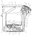
図1は、本発明の実施形態に係る加熱機器である電気ポットを示す。この電気ポットは、外装体10の内部に被加熱物である水を収容する容器22を配設し、この容器22内の水を複数の沸騰ヒータ35,44で加熱するとともに、給湯ポンプ26を動作させることにより、揚水管28を介して吐出部30からお湯を吐出するものである。
FIG. 1 shows an electric pot that is a heating device according to an embodiment of the present invention. In this electric pot, a
前記外装体10は、筒状をなす胴体11と、該胴体11の上部に装着された肩体17と、該肩体17に開閉可能に取り付けた蓋体21を備えている。
The
前記胴体11には、正面に外向きに突出するノーズ部12が設けられ、その先端近傍に下向きに開口した吐出用開口部13が設けられている。また、胴体11の下端開口部は、下板14により閉塞されている。また、胴体11の正面側には、矩形状の開口部15が設けられ、この開口部15に内部を透視可能な透明の窓部材16が配設されている。
The
前記肩体17は、前記胴体11の上端開口と一致する下端形状をなし、その背面側には蓋体21を着脱可能でかつ回動可能に取り付けるためのヒンジ接続部18が設けられている。この肩体17は、ノーズ部12の上側に位置する部分が先端に向けて下向きに湾曲した形状をなし、その部分に操作パネル部19が設けられている。この操作パネル部19の背面側には、下向きに窪む蓋配設部20が設けられ、この蓋配設部20に容器22の内部を露出させる開口部(図示せず)が設けられている。
The
前記蓋体21は、肩体17の蓋配設部20と同一形状をなし、ヒンジ接続部18に軸着されることにより、容器22の上端開口を開閉可能に密閉するものである。この蓋体21は、肩体17に開放不可能な状態にロックし、開放操作によりロックを解除する操作部材(図示せず)を備えている。
The
前記容器22は、肩体17の開口部に装着される円筒状の容器胴体23と、該容器胴体23の下端開口を閉塞する容器底体24とからなる金属製(ステンレス(SUS436L))のものである。容器底体24には、給湯ポンプ26を接続する接続孔25が設けられている。また、給湯ポンプ26には、略L字形状をなす継手部材27を介して窓部材16の背部に位置する揚水管28が接続されている。そして、この揚水管28の上端には、転倒時の漏水を防止するための弁セット29が接続され、この弁セット29に吐出用開口部13内に配置される吐出部30が設けられている。また、容器22には、容器底体24における接続孔25を除く位置に容器22内に向けて上向きに窪むヒータ取付部31が設けられ、このヒータ取付部31の中心に更に円形状をなすように上向きに窪むセンサ配設部32が設けられている。
The
そして、前記容器22のヒータ取付部31には、容器22内に貯留された水を沸騰および保温するための底ヒータユニット34が被覆部材33によって離脱不可能に配設されている。また、本実施形態の容器22には、外周部である容器胴体23の下端に胴ヒータユニット43が配設されている。
A
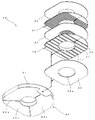
前記底ヒータユニット34は、図2に示すように、底沸騰ヒータ35と、底保温ヒータ36と、各ヒータ35,36間および両端を絶縁する絶縁板39と、これらを内部に積層配置するヒータカバー40とを備えている。底沸騰ヒータ35は、沸騰処理時に動作(通電)されるもので、例えば905Wの出力が可能なものである。底保温ヒータ36は、保温処理時に動作されるもので、例えば65Wの出力が可能なものである。これらヒータ35,36は、中央に貫通孔37aを備えたマイカ板37にニクロム線38を巻回したものである。絶縁板39は、中央に貫通孔39aを備えたマイカ板である。ヒータカバー40は金属(アルミ)製であり、内部のヒータ35,36の発熱を平均化して容器底体24に供給する放熱板の役割をなすもので、ヒータ取付部31より僅かに小さい形状をなすベース板部41と、折り曲げにより該ベース板部41と略同形状をなす3枚の折曲板部42a,42b,42cとを備えている。
As shown in FIG. 2, the
前記胴ヒータユニット43は、図3に示すように、矩形(バンド)状をなす胴沸騰ヒータ44と、平面視C字形状をなす保持枠47と、胴沸騰ヒータ44を保護する保護部材51とを備えている。胴沸騰ヒータ44は、沸騰処理時に動作されるもので、例えば底沸騰ヒータ35と合わせて1200Wとなるように295Wの出力が可能なものである。この胴沸騰ヒータ44は、板状をなすマイカ板45に対して螺旋状をなすようにニクロム線46を巻回したものである。保持枠47は、金属(アルミ)製であり、放熱板の役割をなすもので、内面部48と外面上枠部49と外面下枠部50とを備えた断面略C字形状をなす。保護部材51は、金属(鉄)製であり、容器胴体23の外形より僅かに小さい直径のものである。この保護部材51の両端には、外向きに突出する被締付部52が設けられている。この被締付部52は、図示しない締付金具によってネジ締めされることにより、内側に位置する胴沸騰ヒータ44および保持枠47を容器胴体23に締め付けるものである。なお、この保護部材51には、内側に位置する胴沸騰ヒータ44の接続部46aを露出させる露出孔53が設けられている。
As shown in FIG. 3, the body heater unit 43 includes a
前記電気ポットには、図1に示すように、容器22を介して内部の水温を検出するための温度検出手段であるサーミスタ54が、底ヒータユニット34を貫通してセンサ配設部32に接触するように配設されている。また、容器22と外装体10の底との間には、容器22の底を覆うように底遮熱部材55が配設され、制御基板ケース56に対する底ヒータユニット34の熱を遮断するように構成している。さらに、容器22と外装体10の側部との間には、容器胴体23を覆うように胴遮熱部材57が配設され、揚水管28などの近接した樹脂製品に対する胴ヒータユニット43の熱を遮断するように構成している。
In the electric pot, as shown in FIG. 1, a thermistor 54 that is a temperature detecting means for detecting the water temperature inside through the
なお、前記ノーズ部12の上部外面に形成した操作パネル部19は、図4に示すように、複数のスイッチ59,60,62,63と、複数の表示部65〜69とを備え、これらが操作パネル部19の背部に位置する操作基板58に実装されている。この操作基板58は、後述する制御基板70に接続されている。
The
具体的には、操作パネル部19の中央には、給湯ポンプ26を動作させるための給湯スイッチ59が設けられている。そして、この給湯スイッチ59の右横部には、給湯ポンプ26の動作を許可するためのロック解除スイッチ60が設けられている。また、給湯スイッチ59の下部には、保温温度を90℃、80℃および切(保温なし)のいずれかに選択するための保温選択スイッチ62が設けられている。さらにまた、給湯スイッチ59の左横部には、容器22内の水を再沸騰させるための再沸とうスイッチ63が設けられている。本実施形態のロック解除スイッチ60は、通常の吐出量で給湯するか、通常より少ないドリップ吐出量で給湯するかを選択するための吐出量選択スイッチの役割を兼用する。具体的には、1回目の操作により、通常の吐出量で給湯スイッチ59の操作による給湯処理を可能とする。また、続いて2回目の操作により、給湯可能状態を維持したままで、ドリップ吐出量で給湯処理を可能とする。なお、以後は、操作の度に通常とドリップとを順次変更する。
Specifically, a hot
また、ロック解除スイッチ60の上部には、ドリップ吐出量が選択されていることを示すドリップ表示部65が設けられている。さらに、保温選択スイッチ62の左横部には、90℃保温が選択されていることを示す90℃表示部66が設けられるとともに、その下部に80℃保温が選択されていることを示す80℃表示部67が設けられている。さらにまた、保温選択スイッチ62の右横部には、保温切が選択されていることを示す切表示部68が設けられている。そして、再沸とうスイッチ63の上部には、再沸騰処理の実行状態であることを示す再沸とう表示部69が設けられている。なお、これら各表示部65〜69は、LEDによって構成されている。
In addition, a drip display portion 65 is provided above the
前記電気ポットは、制御基板ケース56内に電源ユニットを含む制御基板70が配設され、この制御基板70に実装した制御手段であるマイコン71により、記憶手段であるROM72に予め記憶されたプログラムに従って沸騰処理、再沸騰処理および保温処理が実行される。そして、本実施形態では、沸騰処理時には、沸騰ヒータ35,44の断線の有無を検出する断線判断工程を実行する構成としている。
In the electric pot, a
具体的には、沸騰処理は、ユーザが電源コードを商用電源に接続すると、または、保温処理中にユーザが水を継ぎ足すことにより10℃以上の温度低下を検出すると、実行されるものである。この沸騰処理では、切換手段であるリレー73を介して並列に接続した沸騰ヒータ35,44を動作させて容器22内の水を加熱し、予め設定された加熱オフ温度(98℃)まで湯温が上昇すると、沸騰ヒータ35,44をオフする。なお、加熱オフ温度は、100℃とした場合には使用場所の標高の違いにより検出できない状況があるうえ、沸騰ヒータ35,44の余熱により突沸が生じる可能性があるため、100℃未満に設定している。
Specifically, the boiling process is executed when the user connects a power cord to a commercial power source or when the user detects a temperature drop of 10 ° C. or more by adding water during the heat retaining process. . In this boiling process, the boiling
再沸騰処理は、ユーザが操作パネル部19の再沸とうスイッチ63を操作すると、実行されるものである。この再沸騰処理では、沸騰処理と同様に、沸騰ヒータ35,44を動作させて容器22内の水を加熱し、予め設定された加熱オフ温度まで湯温が上昇すると、沸騰ヒータ35,44をオフするものである。
The reboiling process is executed when the user operates the reboiling switch 63 of the
保温処理は、沸騰処理または再沸騰処理が終了すると、引き続いて実行されるものである。この保温処理では、ユーザが保温選択スイッチ62の操作により設定した保温温度を維持するように、サーミスタ54の検出温度に基づいて底保温ヒータ36をオンオフ制御する。
The heat retention process is subsequently performed when the boiling process or the reboiling process is completed. In this warming process, the
断線判断工程は、リレー73を介して並列に接続した定格電力が異なる底沸騰ヒータ35および胴沸騰ヒータ44の断線の有無を、サーミスタ54による検出温度に基づいて判断するものである。具体的には、ROM72には、全ての沸騰ヒータ35,44に対して通電した状態(非断線状態)でサーミスタ54によって検出した検出温度の温度上昇勾配と、所定の沸騰ヒータ35,44を意図的に断線させた状態(断線状態)でサーミスタ54によって検出した検出温度の温度上昇勾配と、に基づいて予め判定値Thが設定(記憶)されている。そして、沸騰ヒータ35,44による加熱(沸騰)動作を開始した後に、所定の遅延時間をもってサーミスタ54によって温度の検出を行い、所定時間内に判定値Thを越えるか否かにより沸騰ヒータ35,44が断線しているか否かを判断する構成としている。
In the disconnection determination step, the presence or absence of disconnection of the
ここで、前記判定値Thの設定方法について具体的に説明する。まず、沸騰処理が実行される条件は、前述のように、電力が投入された場合と、水が継ぎ足されることにより10℃以上の温度下降が生じた場合である。そして、水の継ぎ足しに要する時間は、ユーザによって誤差があるうえ、サーミスタ54による検出値も遅れて低下する。そのため、サーミスタ54による判断(検出)開始は、沸騰ヒータ35,44による加熱を開始した後、更に所定の遅延時間(例えば5秒)が経過した後に開始する。また、沸騰ヒータ35,44のいずれかが断線した状態で、長時間加熱動作を行うのは周辺の樹脂部品に影響が及ぶ可能性があるため、判断時間(異常検知時間)はできるだけ短く(例えば10秒)する。さらに、サーミスタ54の検出値による温度上昇勾配は、容器22内に貯留した水量は勿論、沸騰処理を行う供給電力環境や室内環境によって異なる。そのため、判定値Thは、沸騰ヒータ35,44が正常な非断線状態で、最も水温の上昇率が悪い条件(例えば、入力電圧90%、室内温度5℃、水量満水(1500ml))で昇温可能な温度で、かつ、いずれかの沸騰ヒータ35,44(例えば底沸騰ヒータ35)が断線した状態で、最も水温の上昇率が良い条件(例えば、入力電圧110%、室内温度30℃、水量少量(400ml))で昇温不可能な温度に設定(本実施形態では3℃)する。
Here, a method for setting the determination value Th will be described in detail. First, the conditions for performing the boiling process are, as described above, when power is turned on and when a temperature drop of 10 ° C. or more occurs due to the addition of water. The time required for adding water has an error depending on the user, and the value detected by the thermistor 54 also decreases with a delay. Therefore, the determination (detection) start by the thermistor 54 is started after a predetermined delay time (for example, 5 seconds) has elapsed after the heating by the boiling
そして、沸騰処理では、判断時間内に判定値Th以上の温度上昇を検出した場合には、沸騰ヒータ35,44のいずれも断線していない正常状態であると判断し、沸騰処理を継続する。また、判断時間内に判定値Th以上の温度上昇を検出しない場合には、いずれかの沸騰ヒータ35,44が断線している異常状態であると判断し、沸騰処理を停止するとともに異常報知工程を実行する。なお、本実施形態の異常報知工程は、既存の表示部65〜69のうち、90℃表示部66、80℃表示部67、切表示部68および再沸とう表示部69を兼用し、90℃表示部66、80℃表示部67および切表示部68と、再沸とう表示部69とを、交互に点滅させる構成としている。
In the boiling process, when a temperature increase equal to or higher than the determination value Th is detected within the determination time, it is determined that neither of the boiling
また、断線判断工程にていずれかの沸騰ヒータ35,44の断線を検出すると、その異常判断結果を不揮発性の記憶手段であるEEPROM74に記憶させる。そして、沸騰処理の開始時(電力投入時)に、異常判断が所定回数(本実施形態では2回)になっていると、全ての加熱動作、即ち、沸騰処理、再沸騰処理および保温処理を実行不可能としている。
When disconnection of any of the boiling
さらに、ユーザによる水の継ぎ足し作業は、複数回に分けて行われることがある。例えば、電気ポットをシンクから離れた場所に設置している場合で、かつ、容量が少ない容器22に水を入れて運ぶ場合には、異常判断工程中に水が足され、水温が上昇しない(降下する)場合がある。そのため、異常判断工程中にサーミスタ54による検出値が低下(例えば1℃)した場合には、断線判断工程を終了する構成としている。
Furthermore, the user's work of adding water may be performed in multiple steps. For example, when the electric pot is installed in a place away from the sink and when water is carried into the
次に、マイコン71による制御について具体的に説明する。 Next, the control by the microcomputer 71 will be specifically described.
まず、ユーザが商用電源に電源コードを接続することにより電力が投入されると、図5に示すように、マイコン71は、ステップS1で、EEPROM74を読み込み、異常判断回数nが2(回)であるか否かを検出する。そして、異常判断回数nが2でない場合には、ステップS2に進み、異常判断回数nが2である場合には、ステップS12に進む。 First, when the user turns on the power by connecting the power cord to the commercial power source, as shown in FIG. 5, the microcomputer 71 reads the EEPROM 74 in step S1, and the abnormality determination number n is 2 (times). Detect whether or not there is. If the abnormality determination number n is not 2, the process proceeds to step S2. If the abnormality determination number n is 2, the process proceeds to step S12.
ステップS2では、リレー73をオンさせるように信号を出力することにより、底沸騰ヒータ35および胴沸騰ヒータ44をオンさせた後、ステップS3で、遅延タイマ(5秒)をリセットしてスタートさせる。そして、ステップS4で、遅延タイマがカウントアップするまで待機し、遅延タイマがカウントアップするとステップS5に進む。
In step S2, by outputting a signal to turn on the
ステップS5では、後述する断線判断工程を実行した後、ステップS6で、断線していると判断したか否かを示すフラグfが1であるか否(0)かを検出する。そして、fが0(非断線判断)である場合にはステップS7に進み、fが1(断線判断)である場合にはステップS10に進む。 In step S5, after performing a disconnection determination step described later, it is detected whether or not a flag f indicating whether or not it is determined in step S6 that it is disconnected is 1 (0). If f is 0 (non-disconnection determination), the process proceeds to step S7. If f is 1 (disconnection determination), the process proceeds to step S10.
ステップS7では、サーミスタ54によって容器22内の液体が沸騰温度(98℃)に昇温したことを検出するまで待機し、沸騰温度まで昇温するとステップS8に進む。ついで、ステップS8で、ユーザが選択した保温設定に従って保温処理を実行した後、ステップS9で、サーミスタ54によって容器22内の水温が沸騰処理を実行する加熱開始温度まで低下したか否かを検出する。そして、加熱開始温度までの温度降下を検出した場合にはステップS1に戻り、加熱開始温度までの温度降下を検出しない場合にはステップS8に戻る。
In step S7, the process waits until the thermistor 54 detects that the liquid in the
一方、ステップS10では、リレー73をオフさせるように信号を出力することにより、沸騰ヒータ35,44をオフさせた後、ステップS11で、EEPROM74の異常判定回数nに1を加算する。その後、ステップS12で表示部66〜69によって異常報知処理を実行して、全ての制御を終了する。なお、電力を投入した直後のステップS1で、異常判定回数nが2であった場合には、このステップS12に進むことにより、沸騰ヒータ35,44を動作(オン)させることなく、そのまま異常報知工程を実行して終了する。
On the other hand, in step S10, a signal is output so as to turn off the
次に、ステップS5の断線判断工程について具体的に説明する。 Next, the disconnection determination process in step S5 will be specifically described.
この断線判断工程では、図6に示すように、マイコン71は、ステップS5−1で、サーミスタ54によって容器22内の初期水温T0を検出した後、ステップS5−2で、異常検知タイマ(60秒)をリセットしてスタートさせる。
In this disconnection determination step, as shown in FIG. 6, the microcomputer 71 detects the initial water temperature T0 in the
ついで、ステップS5−3で、再びサーミスタ54によって容器22内の水温Tnを検出した後、ステップS5−4で、直前に検出した水温Tn−1と比較し、水温が設定温度(1℃)以上低下したか否かを判断する。そして、水温が設定温度以上低下していない場合にはステップS5−5に進み、水温が設定温度以上低下している場合にはステップS5−9に進む。
Next, in step S5-3, the thermistor 54 again detects the water temperature Tn in the
ステップS5−5では、異常検知タイマがカウントアップした否かを検出する。そして、異常検知タイマがカウントアップした場合にはステップS5−6に進み、カウントアップしていない場合にはステップS5−3に戻る。 In step S5-5, it is detected whether or not the abnormality detection timer has counted up. If the abnormality detection timer has counted up, the process proceeds to step S5-6, and if not counted up, the process returns to step S5-3.
ステップS5−6では、最後に検出した水温Tnから最初に検出した比較基準温度T0との温度差が、判定値Th以上であるか否かを検出する。そして、温度差が判定値未満(Tn−T0<Th)である場合には、沸騰ヒータ35,44のいずれかが断線していると判断してステップS5−7に進み、断線判断フラグfに1を入力してリターンする。また、温度差が判定値以上(Tn−T0≧Th)である場合には、沸騰ヒータ35,44のいずれも断線していないと判断してステップS5−8に進み、断線判断フラグfに0を入力してリターンする。
In step S5-6, it is detected whether or not the temperature difference between the water temperature Tn detected last and the comparison reference temperature T0 detected first is equal to or greater than the determination value Th. If the temperature difference is less than the determination value (Tn−T0 <Th), it is determined that one of the boiling
一方、ステップS5−4で、容器22内の水温が低下したことを検出した場合には、ステップS5−9で、異常検出タイマを停止させてステップS5−8に進む。これにより、メインフローに戻ると、通常の沸騰処理が継続されることになる。
On the other hand, if it is detected in step S5-4 that the water temperature in the
このように、本実施形態の電気ポットでは、既存のサーミスタ54の検出値と、予め設定した判定値Thによって沸騰ヒータ35,44の断線の有無を判断するため、従来から既存の制御基板70の設計変更は必要ない。そのため、安価かつ容易に実現可能である。そして、この構成は、本実施形態のように、定格電力が異なる底沸騰ヒータ35および胴沸騰ヒータ44を適用した状態で、定格電力が高い沸騰ヒータ35が断線している場合には、その断線状態を確実に検出できる。
As described above, in the electric pot of the present embodiment, since the presence or absence of disconnection of the boiling
また、断線判断工程によっていずれかの沸騰ヒータ35,44が断線しているという異常判断をした場合には、沸騰ヒータ35,44による加熱動作を停止するため、異常状態で加熱を継続することによって、周囲の樹脂部品が溶損するなどの問題が生じることを防止できる。しかも、異常状態を表示部66〜69にて表示するため、その異常状態を確実にユーザに知らせることができる。しかも、異常判断が所定回数以上の場合には、沸騰ヒータ35,44による加熱動作(沸騰処理)を実行不可能とするため、短い時間でも加熱動作を行うことによる更なる異常が発生することを確実に防止できる。
In addition, when it is determined that any of the boiling
さらに、電気ポットの場合には、ユーザが水を継ぎ足すことにより沸騰処理を実行し、その直後はサーミスタ54による検出温度は低下するため、正確な異常判断を行うことができない。しかし、本実施形態では、所定の遅延時間を経て断線判断工程を実行するため、確実に断線の有無を検出することができる。しかも、ユーザが複数回に分けて水の継ぎ足しを行った場合には、水温が上昇しないため、沸騰ヒータ35,44が断線していないにも拘わらず断線していると判断する可能性がある。しかし、本実施形態では、断線判断工程の実行中にサーミスタ54による検出温度が低下した場合には断線判断工程を終了するため、誤判断を防止できる。
Furthermore, in the case of an electric pot, the boiling process is executed by the user adding water, and immediately after that, the temperature detected by the thermistor 54 is lowered, so that an accurate abnormality determination cannot be made. However, in the present embodiment, since the disconnection determination step is executed after a predetermined delay time, it is possible to reliably detect the presence or absence of disconnection. In addition, when the user adds water several times, the water temperature does not rise, so there is a possibility that it is determined that the boiling
なお、本発明の加熱機器は、前記実施形態の構成に限定されるものではなく、種々の変更が可能である。 In addition, the heating apparatus of this invention is not limited to the structure of the said embodiment, A various change is possible.
例えば、前記実施形態では、断線判断工程の実行中にサーミスタ54による検出温度が低下すると、断線判断工程自体を終了(ステップS5−9)する構成としたが、ステップS5−1に戻り、低下した温度を比較基準温度T0として断線判断工程を再スタートする構成としてもよい。このようにすれば、ステップS3,4の断線判断工程の開始時間を調整するための遅延時間は不要である。 For example, in the above-described embodiment, when the temperature detected by the thermistor 54 is reduced during the disconnection determination process, the disconnection determination process itself is terminated (step S5-9), but the process returns to step S5-1 and decreases. It is good also as a structure which restarts a disconnection judgment process by making temperature into comparison reference temperature T0. In this way, the delay time for adjusting the start time of the disconnection determination process in steps S3 and S4 is not necessary.
また、前記実施形態では、予め設定した遅延時間が経過(ステップS4)すると断線判断工程(ステップS5)を実行するようにしたが、この遅延時間の計時中(ステップS4)に、サーミスタ54によって湯温を検出し、検出温度の低下(例えば1℃)を検出すると、計測時間をクリアして再び遅延時間の計測を行う(ステップS3に戻る)ようにしてもよい。このようにすれば、遅延時間の計測中にユーザが複数回に分けて水の継ぎ足しを行った場合でも、断線判断工程にて確実に断線の有無を検出することができる。 In the above embodiment, the disconnection determination step (step S5) is executed when the preset delay time has elapsed (step S4). However, the thermistor 54 performs hot water measurement while the delay time is being measured (step S4). When the temperature is detected and a decrease in the detected temperature (for example, 1 ° C.) is detected, the measurement time may be cleared and the delay time may be measured again (return to step S3). In this way, even when the user adds water several times during the measurement of the delay time, the presence or absence of disconnection can be reliably detected in the disconnection determination step.
さらに、前記実施形態では、沸騰ヒータ35,44の断線を検出すると、既存の表示部66〜69を利用してユーザに報知する構成としたが、専用の表示部を設けてもよい。
Furthermore, in the said embodiment, when the disconnection of the boiling
そして、前記実施形態では、沸騰ヒータ35,44の異常判断を電気ポットを例に挙げて説明したが、加湿器や炊飯器など、容器22にヒータを取り付ける加熱機器であればいずれでも適用可能であり、同様の作用および効果を得ることができる。
And in the said embodiment, although the abnormality judgment of the boiling
10…外装体
11…胴体
17…肩体
21…蓋体
22…容器
34…底ヒータユニット
35…底沸騰ヒータ
36…底保温ヒータ
43…胴ヒータユニット
44…胴沸騰ヒータ
54…サーミスタ(温度検出手段)
71…マイコン(制御手段)
74…EEPROM(記憶手段)
DESCRIPTION OF
71: Microcomputer (control means)
74 ... EEPROM (storage means)
Claims (4)
非断線状態で前記ヒータに対して通電した際の前記温度検出手段の検出値による温度上昇勾配と、いずれかが断線した状態で前記ヒータに対して通電した際の前記温度検出手段の検出値による温度上昇勾配とに基づいて予め判定値を設定し、
前記ヒータによる加熱動作時に、所定時間内に前記判定値を越えるか否かによりいずれかのヒータが断線したことを判断する断線判断工程を実行するようにし、
前記断線判断工程の実行時に、前記温度検出手段による検出温度が低下すると、該断線判断工程を終了するようにしたことを特徴とする加熱機器。 Two or more heaters connected in parallel and a temperature detection means for detecting the temperature of the object to be heated via the container are disposed in a container for storing the object to be heated, and based on the detected temperature of the temperature detection means. In the heating device that controls the heater and heats the object to be heated,
According to the temperature rise gradient based on the detected value of the temperature detecting means when the heater is energized in a non-disconnected state, and the detected value of the temperature detecting means when the heater is energized in a state where either is disconnected Based on the temperature rise gradient, set a judgment value in advance,
During the heating operation by the heater, a disconnection determination step is performed to determine that any of the heaters is disconnected depending on whether the determination value is exceeded within a predetermined time ,
A heating device characterized in that the disconnection determination step is terminated when the temperature detected by the temperature detecting means decreases during the disconnection determination step .
非断線状態で前記ヒータに対して通電した際の前記温度検出手段の検出値による温度上昇勾配と、いずれかが断線した状態で前記ヒータに対して通電した際の前記温度検出手段の検出値による温度上昇勾配とに基づいて予め判定値を設定し、
前記ヒータによる加熱動作時に、所定時間内に前記判定値を越えるか否かによりいずれかのヒータが断線したことを判断する断線判断工程を実行するようにし、
前記断線判断工程を、前記ヒータによる加熱動作の実行から所定の遅延時間を経て開始するようにし、かつ、前記遅延時間の計時中に前記温度検出手段によって温度の低下を検出すると計測時間をクリアして再び計測を行うようにしたことを特徴とする加熱機器。 Two or more heaters connected in parallel and a temperature detection means for detecting the temperature of the object to be heated via the container are disposed in a container for storing the object to be heated, and based on the detected temperature of the temperature detection means. In the heating device that controls the heater and heats the object to be heated,
According to the temperature rise gradient based on the detected value of the temperature detecting means when the heater is energized in a non-disconnected state, and the detected value of the temperature detecting means when the heater is energized in a state where either is disconnected Based on the temperature rise gradient, set a judgment value in advance,
During the heating operation by the heater, a disconnection determination step is performed to determine that any of the heaters is disconnected depending on whether the determination value is exceeded within a predetermined time ,
The disconnection determination step is started after a predetermined delay time from the execution of the heating operation by the heater, and the measurement time is cleared when the temperature detecting means detects a temperature drop during the delay time measurement. Heating equipment characterized in that measurement is performed again .
Priority Applications (1)
| Application Number | Priority Date | Filing Date | Title |
|---|---|---|---|
| JP2008136589A JP4987798B2 (en) | 2008-05-26 | 2008-05-26 | Heating equipment |
Applications Claiming Priority (1)
| Application Number | Priority Date | Filing Date | Title |
|---|---|---|---|
| JP2008136589A JP4987798B2 (en) | 2008-05-26 | 2008-05-26 | Heating equipment |
Publications (2)
| Publication Number | Publication Date |
|---|---|
| JP2009279314A JP2009279314A (en) | 2009-12-03 |
| JP4987798B2 true JP4987798B2 (en) | 2012-07-25 |
Family
ID=41450397
Family Applications (1)
| Application Number | Title | Priority Date | Filing Date |
|---|---|---|---|
| JP2008136589A Active JP4987798B2 (en) | 2008-05-26 | 2008-05-26 | Heating equipment |
Country Status (1)
| Country | Link |
|---|---|
| JP (1) | JP4987798B2 (en) |
Family Cites Families (3)
| Publication number | Priority date | Publication date | Assignee | Title |
|---|---|---|---|---|
| JPH1165358A (en) * | 1997-08-20 | 1999-03-05 | Ricoh Co Ltd | Fixing device |
| JPH11149973A (en) * | 1997-11-18 | 1999-06-02 | Zojirushi Corp | Heating device using heater |
| JP2002300965A (en) * | 2001-04-04 | 2002-10-15 | Tiger Vacuum Bottle Co Ltd | Electric pot and failure diagnostic method therefor |
-
2008
- 2008-05-26 JP JP2008136589A patent/JP4987798B2/en active Active
Also Published As
| Publication number | Publication date |
|---|---|
| JP2009279314A (en) | 2009-12-03 |
Similar Documents
| Publication | Publication Date | Title |
|---|---|---|
| US20240183580A1 (en) | Electronic Control System for Electric Water Heater | |
| MXPA02000283A (en) | Method and apparatus for detecting a dry fire condition in a water heater. | |
| KR102258678B1 (en) | cover for centrifugal pump | |
| US9494311B2 (en) | Flow heaters | |
| JP5128589B2 (en) | Home appliances for liquid heating | |
| CA2366279A1 (en) | Water heater having dual side-by-side heating elements | |
| JP2016084960A (en) | Hot water storage type electric water heater | |
| ES2272284T3 (en) | METHOD OF DETECTION OF INCRUSTATIONS IN A COFFEE MACHINE. | |
| CN109068931A (en) | Long-term reliability and the rinsing maching that the safety is improved | |
| JP4987798B2 (en) | Heating equipment | |
| JP5038107B2 (en) | Electric kettle manufacturing method | |
| NL1010064C2 (en) | Regulating and checking for safety aspects of heating systems for liquids using electric heating elements as a sensor. | |
| JP2011224288A (en) | Electric water heater | |
| KR101247669B1 (en) | Hot water heater and method for preventing overheating of hot water heater | |
| JP2001324219A (en) | Electric water heater | |
| JP5300382B2 (en) | rice cooker | |
| JP2920191B2 (en) | Electromagnetic rice cooker | |
| JPS6029936Y2 (en) | Empty cooking prevention device for electric rice cooker | |
| JP2008036009A (en) | Electric water boiler | |
| JP2001000317A (en) | Rice cooker | |
| KR20140006185U (en) | hot water heater | |
| JP4178747B2 (en) | Hot water storage type electric water heater | |
| CA1148599A (en) | Thermostat control system for an electric kettle | |
| JPS6226029Y2 (en) | ||
| JPS63271060A (en) | Electric hot water heater |
Legal Events
| Date | Code | Title | Description |
|---|---|---|---|
| A621 | Written request for application examination |
Free format text: JAPANESE INTERMEDIATE CODE: A621 Effective date: 20100304 |
|
| A977 | Report on retrieval |
Free format text: JAPANESE INTERMEDIATE CODE: A971007 Effective date: 20120227 |
|
| A131 | Notification of reasons for refusal |
Free format text: JAPANESE INTERMEDIATE CODE: A131 Effective date: 20120306 |
|
| A521 | Request for written amendment filed |
Free format text: JAPANESE INTERMEDIATE CODE: A523 Effective date: 20120405 |
|
| TRDD | Decision of grant or rejection written | ||
| A01 | Written decision to grant a patent or to grant a registration (utility model) |
Free format text: JAPANESE INTERMEDIATE CODE: A01 Effective date: 20120424 |
|
| A01 | Written decision to grant a patent or to grant a registration (utility model) |
Free format text: JAPANESE INTERMEDIATE CODE: A01 |
|
| A61 | First payment of annual fees (during grant procedure) |
Free format text: JAPANESE INTERMEDIATE CODE: A61 Effective date: 20120425 |
|
| R150 | Certificate of patent or registration of utility model |
Free format text: JAPANESE INTERMEDIATE CODE: R150 Ref document number: 4987798 Country of ref document: JP Free format text: JAPANESE INTERMEDIATE CODE: R150 |
|
| FPAY | Renewal fee payment (event date is renewal date of database) |
Free format text: PAYMENT UNTIL: 20150511 Year of fee payment: 3 |
|
| R250 | Receipt of annual fees |
Free format text: JAPANESE INTERMEDIATE CODE: R250 |
|
| R250 | Receipt of annual fees |
Free format text: JAPANESE INTERMEDIATE CODE: R250 |
|
| R250 | Receipt of annual fees |
Free format text: JAPANESE INTERMEDIATE CODE: R250 |
|
| R250 | Receipt of annual fees |
Free format text: JAPANESE INTERMEDIATE CODE: R250 |