JP4987130B2 - Ball tank equipment - Google Patents

Ball tank equipment Download PDF

Info

Publication number
JP4987130B2
JP4987130B2 JP2011026544A JP2011026544A JP4987130B2 JP 4987130 B2 JP4987130 B2 JP 4987130B2 JP 2011026544 A JP2011026544 A JP 2011026544A JP 2011026544 A JP2011026544 A JP 2011026544A JP 4987130 B2 JP4987130 B2 JP 4987130B2
Authority
JP
Japan
Prior art keywords
ball
return
tank body
tank
ball return
Prior art date
Legal status (The legal status is an assumption and is not a legal conclusion. Google has not performed a legal analysis and makes no representation as to the accuracy of the status listed.)
Expired - Fee Related
Application number
JP2011026544A
Other languages
Japanese (ja)
Other versions
JP2011088016A5 (en
JP2011088016A (en
Inventor
詔八 鵜川
Current Assignee (The listed assignees may be inaccurate. Google has not performed a legal analysis and makes no representation or warranty as to the accuracy of the list.)
Sankyo Co Ltd
Original Assignee
Sankyo Co Ltd
Priority date (The priority date is an assumption and is not a legal conclusion. Google has not performed a legal analysis and makes no representation as to the accuracy of the date listed.)
Filing date
Publication date
Application filed by Sankyo Co Ltd filed Critical Sankyo Co Ltd
Priority to JP2011026544A priority Critical patent/JP4987130B2/en
Publication of JP2011088016A publication Critical patent/JP2011088016A/en
Publication of JP2011088016A5 publication Critical patent/JP2011088016A5/ja
Application granted granted Critical
Publication of JP4987130B2 publication Critical patent/JP4987130B2/en
Anticipated expiration legal-status Critical
Expired - Fee Related legal-status Critical Current

Links

Images

Description

本発明は、遊技機から排出される排出玉を受け入れて、玉回収樋に向けて該排出玉を返却する玉タンク装置に係り、さらに詳しくは、排出玉を詰まらせることなく返却可能な玉タンク装置に関する。   The present invention relates to a ball tank device that accepts discharged balls discharged from a gaming machine and returns the discharged balls to a ball collecting basket, and more specifically, a ball tank that can be returned without clogging the discharged balls. Relates to the device.

従来より、パチンコ機等の遊技機が長手方向に並列して設置される遊技島の内部には、パチンコ機に対応するように並列して配置され、パチンコ機から落下排出されるパチンコ玉(即ち排出玉)を受け入れて返却する前記玉タンク装置,遊技島の長手方向左右両端側から中央に向かう方向に下り傾斜して配置され、玉タンク装置から返却されたパチンコ玉を回収する玉回収樋,及び遊技島の中央に配置され、玉回収樋により回収されたパチンコ玉を研磨して揚送する玉研磨揚送装置等が備えられている。   Conventionally, a pachinko ball (i.e., a pachinko machine or the like) that is arranged in parallel so as to correspond to the pachinko machine and is discharged from the pachinko machine (i.e., a pachinko machine) The ball tank device that receives and returns the discharged balls), a ball collection basket that is arranged so as to be inclined downward from the left and right ends in the longitudinal direction of the game island toward the center and collects pachinko balls returned from the ball tank device, And a ball polishing and lifting device that is disposed in the center of the amusement island and that polishes and lifts pachinko balls collected by a ball collecting basket.

ここで玉タンク装置においては、パチンコ機から落下排出されるパチンコ玉がタンク部本体により受け入れられ、受け入れられたパチンコ玉が返却シュートにより誘導されて玉返却口から返却され、返却されたパチンコ玉が玉計数機により計数され、計数されたパチンコ玉が蛇腹状の玉返却管から返却されて玉回収樋により回収される。しかしながら、玉返却管と玉回収樋との隙間が狭いとパチンコ玉が詰まる場合があり、特に遊技島の長手方向左右両端寄りにおいては、前記下り傾斜している玉回収樋が高いところに位置して前記隙間が狭くなることから、両者の隙間はなるべく広く取る必要がある。   Here, in the ball tank device, the pachinko ball dropped and discharged from the pachinko machine is received by the tank body, the accepted pachinko ball is guided by the return chute and returned from the ball return port, and the returned pachinko ball is The pachinko balls counted by the ball counter are returned from the bellows-shaped ball return tube and collected by a ball collecting basket. However, if the gap between the ball return tube and the ball collection basket is narrow, the pachinko balls may be clogged, and the ball collection basket that is inclined downward is located at a high position, especially near the left and right ends in the longitudinal direction of the game island. Therefore, the gap between the two needs to be as wide as possible.

そこで従来の玉タンク装置は、例えば特許文献1に記載されるように、パチンコ玉を玉タンク装置の右側又は左側のいずれかより返却する別個の返却シュートを着脱自在に設け、いずれか選択して取り付けた返却シュートによりパチンコ玉を左右いずれかに振り分けて返却していた。   Therefore, as described in Patent Document 1, for example, the conventional ball tank device is detachably provided with a separate return chute that returns the pachinko balls from either the right side or the left side of the ball tank device, and selects either of them. The pachinko balls were distributed to either the left or right by the attached return chute and returned.

具体的には、例えばパチンコ機が遊技島の左端寄りに位置する場合には、玉タンク装置に排出されたパチンコ玉を右側から返却するための右側返却用の返却シュートを取り付け、逆にパチンコ機が遊技島の右端寄りに位置する場合には、玉タンク装置に排出されたパチンコ玉を左側から返却するための左側返却用の返却シュートを取り付けることにより、玉返却管と玉回収樋との隙間をなるべく広く取り、パチンコ玉を詰まらせることなく返却するようにしていた。   Specifically, for example, when the pachinko machine is located near the left end of the amusement island, a return chute for returning the right side to return the pachinko balls discharged to the ball tank device is attached, and conversely the pachinko machine Is located near the right edge of the amusement island, by attaching a return chute for returning left pachinko balls discharged to the ball tank device from the left side, the gap between the ball return tube and the ball collection basket Was taken as wide as possible and returned without clogging pachinko balls.

特開平9−155034号公報Japanese Patent Laid-Open No. 9-1555034

しかしながら、従来の玉タンク装置においては、右側返却用の返却シュートと左側返却用の返却シュートとは互換性のない別個の部材であるため、例えば遊技場が多量の玉タンク装置を発注する場合には、左右いずれの返却シュートがそれぞれ何個必要であるかを正確に把握した上で発注する必要があり、また仮に左右の返却シュートの必要数量を間違えて発注した場合には、それらの間に互換性がないため、再度発注し直す必要があるという問題があった。   However, in the conventional ball tank device, the return chute for returning the right side and the return chute for returning the left side are incompatible separate members. For example, when a game hall orders a large number of ball tank devices. It is necessary to place an order after knowing exactly how many return chutes are required for each of the left and right, and if the wrong quantity of left and right return chutes is ordered, There was a problem that it was necessary to reorder again because of incompatibility.

本発明は、このような背景のもとになされたものであり、その目的は、排出玉を任意の方向から振り分けて返却することができ、排出玉を詰まらせることなく返却可能な玉タンク装置を提供することにある。   The present invention has been made based on such a background, and an object of the present invention is to provide a ball tank device that can return and return discharged balls from any direction without clogging the discharged balls. Is to provide.

本発明は、前記課題を解決するために、次のような手段を採る。なお後述する発明を実施するための最良の形態の説明及び図面で使用した符号を参考のために括弧書きで付記するが、本発明の構成要素は該付記したものには限定されない。   The present invention adopts the following means in order to solve the above problems. The reference numerals used in the description of the best mode for carrying out the invention and the drawings to be described later are appended in parentheses for reference, but the constituent elements of the present invention are not limited to the appended description.

まず手段1に係る発明は、遊技機から排出される排出玉を受け入れて、玉回収樋に向けて該排出玉を返却する玉タンク装置であって、前記排出玉を受け入れるタンク部本体と、前記タンク部本体の長手方向左右両端側に各々設けられ、前記排出玉を前記玉回収樋に向けて返却するための玉返却口を備えた玉返却部と、前記玉返却部に設けられた玉返却口のうち、いずれかの玉返却口に向けて前記排出玉を誘導する玉誘導部と、を備えることを特徴とする玉タンク装置である。 First invention of the means 1 accepts the discharge ball discharged from the gaming machine, a ball tank device to return the exhaust payout towards the ball collecting trough, the tank body for receiving the discharge ball, the each is provided in the longitudinal direction of both left and right ends of the tank body, and a ball return unit for the discharge ball painting Bei ball return opening for returning towards the ball collecting gutter, a ball return provided in the coin return unit A ball tank device comprising: a ball guiding portion that guides the discharged balls toward one of the ball return ports.

上記課題を解決するための手段の具体例を、発明の実施の形態及び図面の表記と対応させて説明する。以下の実施例においては、玉誘導部には玉誘導部材15が対応する。玉整列部には玉整列部材53が対応し、第一の取付部には整列部材取付部14dが対応する。計数機取付部には計数機取付部材52が対応し、第二の取付部には取付部材係合部14cが対応する。タンク部本体取付部には本体係合爪14e’が対応する。他の計数機取付部には計数機取付部材52’が対応し、第三の取付部には取付部材係合孔10h’が対応する。   Specific examples of means for solving the above problems will be described in correspondence with the embodiments of the invention and the notation of the drawings. In the following embodiments, the ball guiding member 15 corresponds to the ball guiding portion. The ball alignment member 53 corresponds to the ball alignment portion, and the alignment member attachment portion 14d corresponds to the first attachment portion. The counter mounting member 52 corresponds to the counter mounting portion, and the mounting member engaging portion 14c corresponds to the second mounting portion. A main body engaging claw 14e 'corresponds to the tank main body mounting portion. The counter mounting member 52 'corresponds to the other counter mounting portion, and the mounting member engaging hole 10h' corresponds to the third mounting portion.

まず手段1に係る玉タンク装置によれば、玉誘導部の作用によって、タンク部本体の長手方向左右両端側に各々設けられる玉返却口のうちの選択されたいずれか任意の玉返却口からパチンコ玉を振り分けて返却することができ、排出玉を詰まらせることなく返却可能である。従って、例えば遊技場が多量の玉タンク装置を発注する場合であっても、一種類の玉タンク装置を必要数量だけ発注すれば足りるという効果を奏する。 First, according to the ball tank apparatus according to the means 1, the pachinko from any selected ball return port among the ball return ports respectively provided on the left and right ends in the longitudinal direction of the tank body by the action of the ball guiding unit. The balls can be sorted and returned, and can be returned without clogging the discharged balls. Therefore, for example, even when a game hall orders a large amount of ball tank devices, it is sufficient to order only one quantity of one kind of ball tank device.

図1は玉タンク装置を表す斜視図である。FIG. 1 is a perspective view showing a ball tank apparatus. 図2はタンク部本体,内部支持脚,外部支持脚,及び支持土台を表す分解斜視図である。FIG. 2 is an exploded perspective view showing the tank body, the internal support legs, the external support legs, and the support base. 図3(a)はタンク部本体を表す部分平面図であり、図3(b)は同正面図である。FIG. 3A is a partial plan view showing the tank body, and FIG. 3B is a front view thereof. 図4(a)は玉誘導部材を表す斜視図であり、図4(b)は該玉誘導部材の取付状態を表す断面側面図である。FIG. 4A is a perspective view showing the ball guiding member, and FIG. 4B is a cross-sectional side view showing the mounting state of the ball guiding member. 図5(a)は計数機取付部材を表す斜視図であり、図5(b)は該計数機取付部材の取付状態を表す断面側面図である。Fig.5 (a) is a perspective view showing a counter attachment member, FIG.5 (b) is a cross-sectional side view showing the attachment state of this counter attachment member. 図6は玉整列部材を表す正面図である。FIG. 6 is a front view showing the ball alignment member. 図7はパチンコ玉が右側に返却される場合における玉誘導部材,計数機取付部材,及び玉整列部材の取付状態を表す正面図である。FIG. 7 is a front view showing the mounting state of the ball guiding member, the counter mounting member, and the ball alignment member when the pachinko ball is returned to the right side. 図8はパチンコ玉が左側に返却される場合における玉誘導部材,計数機取付部材,及び玉整列部材の取付状態を表す正面図である。FIG. 8 is a front view showing the mounting state of the ball guiding member, the counter mounting member, and the ball alignment member when the pachinko ball is returned to the left side. 図9は変形例に係るタンク部本体,及び玉返却シュートを表す斜視図である。FIG. 9 is a perspective view showing a tank body and a ball return chute according to a modification. 図10(a)は変形例に係るタンク部本体において、パチンコ玉が右側に返却される場合における玉返却シュート,計数機取付部材,及び玉整列部材の取付状態を表す部分平面図であり、図10(b)は同正面図である。FIG. 10A is a partial plan view showing the mounting state of the ball return chute, the counter mounting member, and the ball alignment member when the pachinko ball is returned to the right side in the tank body according to the modification. 10 (b) is a front view of the same. 図11(a)は変形例に係るタンク部本体において、パチンコ玉が左側に返却される場合における玉返却シュート,計数機取付部材,及び玉整列部材の取付状態を表す部分平面図であり、図11(b)は同正面図である。FIG. 11A is a partial plan view showing the mounting state of the ball return chute, the counter mounting member, and the ball alignment member when the pachinko ball is returned to the left side in the tank body according to the modification. 11 (b) is a front view of the same. 図12は内部支持脚を表す斜視図である。FIG. 12 is a perspective view showing the internal support leg. 図13は外部支持脚を表す斜視図である。FIG. 13 is a perspective view showing an external support leg. 図14は玉タンク装置を表す断面平面図である。FIG. 14 is a sectional plan view showing the ball tank apparatus. 図15は玉タンク装置を表す断面正面図である。FIG. 15 is a cross-sectional front view showing the ball tank apparatus. 図16は玉タンク装置を表す部分断面右側面図である。FIG. 16 is a partial cross-sectional right side view showing the ball tank apparatus. 図17(a)は左右方向移動用の目盛と目印,及び上下方向移動用の目盛と目印を表す斜視図であり、図17(b)は前後方向移動用の目盛と目印を表す右側面図である。17A is a perspective view showing a scale and a mark for moving in the left-right direction, and a scale and mark for moving in the up-down direction, and FIG. 17B is a right side view showing the scale and the mark for moving in the front-rear direction. It is.

以下、本発明の実施の形態を、図面を参照して説明する。なお、以下においては、遊技機として、パチンコ玉を遊技媒体とするパチンコ機3を例に説明を行う。また、以下においては、図1に示すように、玉回収樋5側を前,パチンコ機3側を後とし、パチンコ機3の幅方向(即ち遊技島の長手方向)を左右方向,高さ方向を上下方向,奥行き方向を前後方向と称する。   Hereinafter, embodiments of the present invention will be described with reference to the drawings. In the following description, a pachinko machine 3 using a pachinko ball as a game medium will be described as an example of the gaming machine. In the following, as shown in FIG. 1, the ball collecting basket 5 side is the front, the pachinko machine 3 side is the rear, the width direction of the pachinko machine 3 (ie, the longitudinal direction of the amusement island) is the left-right direction, and the height direction. Is called the vertical direction, and the depth direction is called the front-back direction.

[1.玉タンク装置の構成]
まず、本発明に係る玉タンク装置1の構成について説明する。玉タンク装置1は、図1に示すように、パチンコ機3から排出されるパチンコ玉(即ち排出玉)を受け入れて、玉回収樋5に向けて該排出玉を返却するものであり、図2に示すタンク部本体10を備えるものと、図9に示す変形例に係るタンク部本体10’を備えるものとが含まれる。以下においては、主にタンク部本体10を備える玉タンク装置1について説明を行い、変形例に係るタンク部本体10’を備える玉タンク装置については、タンク部本体10を備える玉タンク装置1と異なる点についてのみ説明を行う。
[1. Configuration of ball tank device]
First, the structure of the ball tank apparatus 1 which concerns on this invention is demonstrated. As shown in FIG. 1, the ball tank apparatus 1 accepts pachinko balls (that is, discharged balls) discharged from the pachinko machine 3, and returns the discharged balls to the ball collecting basket 5 as shown in FIG. And a tank unit main body 10 ′ according to the modification shown in FIG. 9 are included. In the following, the ball tank apparatus 1 including the tank body 10 is mainly described, and the ball tank apparatus including the tank body 10 ′ according to the modification is different from the ball tank apparatus 1 including the tank body 10. Only the point will be described.

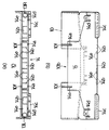
玉タンク装置1は、図1に示すように、遊技島の内部において、設置台2に取り付けられて用いられる。ここで設置台2は、長手方向に亘って所定の長さを有する台である。この設置台2の表面側には、長手方向に亘って複数のパチンコ機3が並列して取り付けられている。このパチンコ機3の裏面における略中央には、玉排出口4が設けられている。また設置台2の上面における各パチンコ機3の中央背後には、タンク部本体10(又は10’)が玉排出口4に臨むように、後述する支持土台40がビス等で固定されて、長手方向に亘って複数の玉タンク装置1が並列して取り付けられている。さらに遊技島の内部における設置台2よりも低い位置には、長手方向左右両端側から中央に向かう方向に下り傾斜して配置される玉回収樋5が設けられている。   As shown in FIG. 1, the ball tank device 1 is used by being attached to an installation base 2 inside the amusement island. Here, the installation table 2 is a table having a predetermined length in the longitudinal direction. A plurality of pachinko machines 3 are attached in parallel to the surface side of the installation table 2 in the longitudinal direction. A ball discharge port 4 is provided in the approximate center of the back surface of the pachinko machine 3. Further, a support base 40 (described later) is fixed with a screw or the like behind the center of each pachinko machine 3 on the upper surface of the installation base 2 so that the tank body 10 (or 10 ') faces the ball outlet 4 and is long. A plurality of ball tank devices 1 are mounted in parallel across the direction. Further, at a position lower than the installation base 2 inside the amusement island, a ball collection basket 5 is provided which is disposed so as to be inclined downward from the left and right ends in the longitudinal direction toward the center.

また玉タンク装置1には、タンク部本体10に受け入れられた排出玉を玉回収樋5に向けて返却するための玉返却口13R,13L(又は図9に示すように、タンク部本体10’に受け入れられた排出玉を玉回収樋5に向けて返却するための玉返却口13R’,13L’)が設けられている。なお複数の玉返却口を特に区別しない場合には、単に「玉返却口13」(又は「玉返却口13’」)という。   Also, the ball tank device 1 has ball return ports 13R and 13L (or tank portion main body 10 ′ as shown in FIG. 9) for returning the discharged balls received by the tank portion main body 10 toward the ball collecting basket 5. Are provided with ball return ports 13R ′, 13L ′) for returning the discharged balls received to the ball collecting basket 5. If there is no particular distinction between a plurality of ball return openings, they are simply referred to as “ball return openings 13” (or “ball return openings 13 '”).

さらに玉タンク装置1には、後述する計数機取付部材52(又は52’),及び玉整列部材53が設けられている。この計数機取付部材52(又は52’)には、玉返却口13から返却された排出玉を計数するためのボックス状の玉計数機50が取り付けられており、また玉計数機50からは、通過するパチンコ玉の勢いを弱めるための蛇腹状の玉返却管51が垂下されている。   Further, the ball tank device 1 is provided with a counter mounting member 52 (or 52 '), which will be described later, and a ball alignment member 53. A box-shaped ball counter 50 for counting discharged balls returned from the ball return port 13 is attached to the counter mounting member 52 (or 52 ′). A bellows-shaped ball return pipe 51 for dampening the momentum of the passing pachinko balls is suspended.

この遊技島において、パチンコ玉は以下のように流動する。まずパチンコ機3の発射装置により発射されたパチンコ玉は、パチンコ機3の遊技領域に打ち込まれ、遊技領域に設けられた入賞口又はアウト口に取り込まれる。次に入賞口に取り込まれた入賞玉は、景品玉を払い出すための処理を行う入賞玉処理装置を経て、パチンコ機3の玉排出口4から落下排出される。またアウト口に取り込まれたアウト玉は、そのままパチンコ機3の玉排出口4から落下排出される。   In this amusement island, pachinko balls flow as follows. First, the pachinko balls launched by the launching device of the pachinko machine 3 are driven into the game area of the pachinko machine 3 and taken into a winning opening or an out port provided in the game area. Next, the winning ball taken into the winning opening is dropped and discharged from the ball discharging port 4 of the pachinko machine 3 through a winning ball processing device that performs a process for paying out a prize ball. Further, the out ball taken into the out port is dropped and discharged from the ball discharge port 4 of the pachinko machine 3 as it is.

次に玉排出口4から落下排出されたパチンコ玉(即ち排出玉=入賞玉+アウト玉)は、玉タンク装置1のタンク部本体10(又は10’)により受け入れられ、受け入れられたパチンコ玉は玉返却口13から返却され、返却されたパチンコ玉は玉計数機50により計数され、計数されたパチンコ玉は玉返却管51から返却されて玉回収樋5により回収される。   Next, the pachinko balls dropped and discharged from the ball discharge port 4 (that is, discharged balls = winning balls + out balls) are received by the tank body 10 (or 10 ′) of the ball tank device 1, and the received pachinko balls are The pachinko balls returned and returned from the ball return port 13 are counted by the ball counting machine 50, and the counted pachinko balls are returned from the ball return tube 51 and collected by the ball collection basket 5.

そして玉回収樋5により回収されたパチンコ玉は、遊技島の中央に配置される玉研磨揚送装置(図示外)により研磨及び揚送され、パチンコ機3及び必要に応じて玉貸機(図示外)に供給される。   Then, the pachinko balls collected by the ball collecting basket 5 are polished and lifted by a ball polishing and lifting device (not shown) arranged at the center of the amusement island, and the pachinko machine 3 and a ball lending machine (shown) as required. Outside).

なおパチンコ機3等の遊技機においては、排出玉の排出位置がそれぞれのメーカーによって異なっているため、玉タンク装置1を設置台2に取り付けたり、設置台2に取り付けられていた遊技機を異なるメーカーのものに交換する場合に、排出玉の排出位置である玉排出口4の位置に応じて、排出玉の受入位置であるタンク部本体10(又は10’)の取付位置を調節可能とする必要がある。   In the gaming machine such as the pachinko machine 3, the discharge position of the discharged ball is different depending on the manufacturer. Therefore, the ball tank device 1 is attached to the installation base 2 or the gaming machine attached to the installation base 2 is different. When replacing with a manufacturer's one, the mounting position of the tank body 10 (or 10 ') that is the receiving position of the discharged ball can be adjusted according to the position of the ball discharge port 4 that is the discharging position of the discharged ball. There is a need.

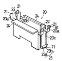
そこで、この玉タンク装置1では、タンク部本体10(又は10’)自体を左右方向,上下方向,及び前後方向の三方向に移動することにより、タンク部本体10(又は10’)の位置調節が可能とされている。具体的には図2に示すように、玉タンク装置1は、主としてタンク部本体10(又は10’),内部支持脚20,外部支持脚30,及び支持土台40の四部品を備え、そのうちの隣接する二部品間(即ち支持土台40と外部支持脚30との間,外部支持脚30と内部支持脚20との間,及び内部支持脚20とタンク部本体10(又は10’)との間)における相対的な移動により、左右方向,上下方向,及び前後方向にタンク部本体10(又は10’)の位置調節が行われる。   Therefore, in this ball tank apparatus 1, the position of the tank body 10 (or 10 ') is adjusted by moving the tank body 10 (or 10') itself in three directions: left and right, up and down, and front and rear. Is possible. Specifically, as shown in FIG. 2, the ball tank apparatus 1 mainly includes four parts of a tank body 10 (or 10 ′), an internal support leg 20, an external support leg 30, and a support base 40, of which Between two adjacent parts (that is, between the support base 40 and the external support leg 30, between the external support leg 30 and the internal support leg 20, and between the internal support leg 20 and the tank body 10 (or 10 ')). ), The position of the tank body 10 (or 10 ′) is adjusted in the left-right direction, the up-down direction, and the front-rear direction.

なお、これら四部品をはじめとして、玉タンク装置1を構成する各構成要素は、例えば硬質の合成樹脂等によって後述する形状に成形される。以下、各構成要素について説明する。   In addition, each component which comprises the ball tank apparatus 1 including these four components is shape | molded by the shape mentioned later with a hard synthetic resin etc., for example. Hereinafter, each component will be described.

[1−1.タンク部本体の構成]
まず図1乃至図8を参照して、タンク部本体10,及びそれに関連する構成について説明する。タンク部本体10は、パチンコ機3から排出される排出玉を受け入れるものであり、図1乃至図3に示すように、ここでは上面が開口し、平面視で横長の長方形状を呈し、正面視で皿状の底板を有する有底容器である。
[1-1. Configuration of tank body]
First, with reference to FIG. 1 thru | or FIG. 8, the tank part main body 10 and the structure relevant to it are demonstrated. The tank body 10 receives the balls discharged from the pachinko machine 3, and as shown in FIG. 1 to FIG. 3, the upper surface is open here and has a horizontally long rectangular shape in plan view, And a bottomed container having a dish-like bottom plate.

タンク部本体10の窪んだ内部は、排出玉を受け入れる受入部10aになっている。このタンク部本体10の内部底面は、図15に示すように、タンク部本体10における端部から中央部に向けて下り傾斜し、かつ図16に示すように、タンク部本体10における後部から前部に向けて下り傾斜しており、受入部10aに受け入れられた排出玉が自重によって転動し、後述する切欠部10bに向けて流下されるようになっている。   The recessed portion of the tank body 10 is a receiving portion 10a that receives the discharged balls. The inner bottom surface of the tank body 10 is inclined downward from the end of the tank body 10 toward the center as shown in FIG. 15, and from the rear of the tank body 10 as shown in FIG. The discharged balls received by the receiving portion 10a roll by their own weight and flow down toward a notch portion 10b described later.

なおタンク部本体10の内部底面には、平面視で逆凸字状を呈する三箇所の弾性体板取付孔10gが設けられ、ゴムシート等の弾性体板(図示外)が該弾性体板取付孔10gに取り付けられて敷設されており、排出玉を受け入れる際に、排出玉が跳ね上がったり衝撃音を発生したりするのを防止している。   The tank body 10 has an inner bottom surface provided with three elastic plate mounting holes 10g having a reverse convex shape in plan view, and an elastic plate (not shown) such as a rubber sheet is attached to the elastic plate. It is laid and attached to the hole 10g to prevent the discharged ball from jumping up or generating an impact sound when receiving the discharged ball.

タンク部本体10の下面には、図15に示すように、外側から順に各二本ずつの板状の固定突片10c,10d,10eが、前後方向に亘って鉛直下向きに突設されている。ここで固定突片10c,10dには、タンク部本体10の前後方向の移動を司る前後被係合部が前後方向に亘って設けられている。具体的には、図17(b)にも示すように、固定突片10cに、前後被係合部を構成する側面視で長方形状の前後案内溝11が、前後方向で所定の範囲に亘って水平に穿設されている。この固定突片10cには、後述する前後方向移動用の目盛80が、前後方向に亘って水平外向きに刻設されている。また、図14にも示すように、固定突片10dに、前後被係合部を構成する平面視で鋸歯状のラック12が、前後方向に亘って水平内向きに延設されている。このラック12の歯は、等辺山形状に形成されてなる。なお固定突片10eは、後述する載置支持片24に載置支持されるものである。   As shown in FIG. 15, two plate-like fixed protrusions 10c, 10d, and 10e are sequentially provided on the lower surface of the tank body 10 so as to protrude vertically downward in the front-rear direction. . Here, the front and rear engaged portions for controlling the movement of the tank body 10 in the front-rear direction are provided in the fixed protrusions 10 c and 10 d in the front-rear direction. Specifically, as shown in FIG. 17B, the front and rear guide grooves 11 that are rectangular in a side view and that constitute the front and rear engaged portions are formed in the fixed protrusion 10c over a predetermined range in the front and rear direction. Are drilled horizontally. A scale 80 for moving in the front-rear direction, which will be described later, is engraved horizontally outward in the front-rear direction on the fixed protrusion 10c. Further, as shown in FIG. 14, a sawtooth rack 12 in a plan view that constitutes the front and rear engaged portions is provided on the fixed protrusion 10 d so as to extend horizontally inward in the front-rear direction. The teeth of the rack 12 are formed in an equilateral mountain shape. The fixed protrusion 10e is placed and supported on a placement support piece 24 described later.

タンク部本体10の前壁における中央部には、図3に示すように、タンク部本体10に受け入れられた排出玉を後述する玉返却部14に向けて流下させるための切欠部10bが設けられている。またタンク部本体10の前壁における切欠部10bの左右両側には、後述する玉誘導部材15の位置決め用突片15fを嵌合するための位置決め用切り込み10f,10fが設けられている。   As shown in FIG. 3, a notch 10 b is provided at the center of the front wall of the tank body 10 to allow the discharged balls received by the tank body 10 to flow toward a ball return portion 14 described later. ing. In addition, positioning notches 10f and 10f for fitting positioning protrusions 15f of a ball guiding member 15 described later are provided on both the left and right sides of the notch 10b on the front wall of the tank body 10.

さらにタンク部本体10の前方には、排出玉を玉回収樋5に向けて返却するための玉返却口13R,13Lを複数備えた玉返却部14が、タンク部本体10の長手方向に沿って設けられている。この玉返却部14は、ここでは正面視で山形を呈する前壁,正面視で谷型を呈する後壁,前壁と後壁の下方においてそれらに連続する側壁,及び底板を有しており、タンク部本体10と一体に設けられ、後述する玉誘導部材15が取り付けられる部位である。   Further, in front of the tank body 10, there is a ball return section 14 provided with a plurality of ball return ports 13 </ b> R and 13 </ b> L for returning the discharged balls toward the ball collection basket 5 along the longitudinal direction of the tank body 10. Is provided. This ball return portion 14 has a front wall that has a mountain shape in front view, a rear wall that has a valley shape in front view, a side wall that continues to the front wall and the rear wall below the rear wall, and a bottom plate. This is a part provided integrally with the tank body 10 and to which a ball guiding member 15 described later is attached.

この玉返却部14の前壁には、位置決め用切り込み10f,10fに対向する箇所に、後述する玉誘導部材15の位置決め用突片15fを嵌合するための位置決め用切り込み14a,14aが設けられている。また玉返却部14の後壁は、タンク部本体10の下縁から連続している。またこれら前壁と後壁との前後方向の間隙は、図4(b)に示すように、玉誘導部材15がぴったりと嵌合可能であると共に、パチンコ玉が一つだけ通過可能な幅に形成されている。   The front wall of the ball return portion 14 is provided with positioning notches 14a and 14a for fitting positioning protrusions 15f of a ball guiding member 15 described later at positions facing the positioning notches 10f and 10f. ing. Further, the rear wall of the ball return unit 14 is continuous from the lower edge of the tank unit body 10. Further, as shown in FIG. 4 (b), the gap between the front wall and the rear wall in the front-rear direction is such that the ball guiding member 15 can be fitted exactly and only one pachinko ball can pass through. Is formed.

また玉返却部14の底板には、図3(a)に示すように、長手方向左右両端側(即ちタンク部本体10の左右両端又はその近傍)に複数の玉返却口13R,13Lが設けられている。この玉返却口13Rは、パチンコ玉を右側から返却するための右側返却用の玉返却口であり、また玉返却口13Lは、パチンコ玉を左側から返却するための左側返却用の玉返却口である。   Further, as shown in FIG. 3A, the ball return portion 14 is provided with a plurality of ball return ports 13R and 13L on the left and right ends in the longitudinal direction (that is, on the left and right ends of the tank body 10 or in the vicinity thereof). ing. This ball return port 13R is a ball return port for returning right side for returning pachinko balls from the right side, and the ball return port 13L is a ball return port for returning left side for returning pachinko balls from the left side. is there.

また玉返却部14の底板には、複数のゴミ落とし口14b(ここでは七つ)が間欠状に設けられており、それら以外の部分の底板が載置部14eとされている。この載置部14eは、図6にも示すように、玉返却部14に取り付けられた後述する玉誘導部材15の支持部15cが載置される位置に形成されており、また図7及び図8にも示すように、向きを変えて玉誘導部材15を取り付けた場合に対応できるように、左右対称の位置に形成されている。   The bottom plate of the ball return unit 14 is provided with a plurality of dust drop openings 14b (seven in this case) in an intermittent manner, and the other part of the bottom plate is a mounting unit 14e. As shown also in FIG. 6, this mounting part 14e is formed in the position where the support part 15c of the ball | bowl guide member 15 mentioned later attached to the ball return part 14 is mounted, and FIG.7 and FIG. As shown also in FIG. 8, it forms in the left-right symmetric position so that it can respond | correspond when it changes the direction and the ball | bowl guide member 15 is attached.

ここで玉誘導部材15は玉誘導部の一例であって、玉返却部14に設けられた複数の玉返却口13R,13Lのうち、いずれかの玉返却口13に向けて排出玉を誘導するためのものであり、図7及び図8に示すように、ここでは玉返却部14に対して着脱可能とされ、その取付態様(具体的には取付の向き)を変更することで、排出玉が返却される玉返却口13を決定するものである。   Here, the ball guiding member 15 is an example of a ball guiding unit, and guides the discharged ball toward one of the ball return ports 13 among the plurality of ball return ports 13R and 13L provided in the ball return unit 14. As shown in FIGS. 7 and 8, here, the ball return portion 14 is detachable, and by changing the mounting mode (specifically, the mounting direction), the discharged balls Is to determine the ball return opening 13 to be returned.

この玉誘導部材15は、図4(a)に示すように、基端側の板材である一つの起立部15aと、起立部15aから先端側に向けて延出する角棒材である一つの傾斜部15bと、傾斜部15bにおける左右両側の適宜の箇所から水平に向けて延出した後に曲折して下方に向けて延出する板材である複数の支持部15cと、起立部15aにおける左右両側の下縁及び傾斜部15bにおける左右両側の適宜の箇所から下方に向けて延出する四つの弾性突片15dと、各弾性突片15dの先端に水平外向きに突設される逆三角形状の固定用係合爪15eと、起立部15aにおける左右両側の上端から水平外向きに突設される二つの位置決め用突片15fとを有する。   As shown in FIG. 4 (a), the ball guiding member 15 includes one upright portion 15a that is a base end side plate material and one square bar material that extends from the upright portion 15a toward the distal end side. Inclined portion 15b, a plurality of support portions 15c which are plates extending horizontally from appropriate portions on both left and right sides of inclined portion 15b and then extending downward, and both left and right sides of standing portion 15a Four elastic protrusions 15d extending downward from appropriate locations on both the left and right sides of the lower edge and the inclined portion 15b, and an inverted triangular shape protruding horizontally outward from the tip of each elastic protrusion 15d. It has a locking engagement claw 15e and two positioning protrusions 15f protruding horizontally outward from the upper left and right ends of the upright portion 15a.

ここで起立部15aは、図7及び図8にも示すように、玉誘導部材15が玉返却部14に取り付けられた状態において、タンク部本体10の切欠部10bから流下された排出玉が、いずれか選択された玉返却口13(例えば玉返却口13R)に向かうように、即ち選択されていない玉返却口13(例えば玉返却口13L)に向かうことがないように、十分な高さ(ここでは玉返却部14の高さと略等しい高さ)に形成される。   Here, as shown in FIG. 7 and FIG. 8, the standing portion 15 a is configured such that in the state where the ball guiding member 15 is attached to the ball returning portion 14, the discharged balls that have flowed down from the notch portion 10 b of the tank body 10 are Sufficiently high so as to go to any selected ball return port 13 (for example, ball return port 13R), that is, not to go to an unselected ball return port 13 (for example, ball return port 13L) ( Here, it is formed at a height substantially equal to the height of the ball return portion 14.

また傾斜部15bは、図7及び図8にも示すように、玉誘導部材15が玉返却部14に取り付けられた状態において、タンク部本体10の切欠部10bから流下された排出玉が、傾斜部15b上を自重により転動していずれか選択された玉返却口13に向かうように、切欠部10bから玉返却口13に至る長さと略等しい長さで、基端部側から先端部側に向けて所定の傾斜角度をもって下り傾斜して形成される。   In addition, as shown in FIGS. 7 and 8, the inclined portion 15 b is inclined when the ball discharged from the notch portion 10 b of the tank main body 10 is inclined when the ball guiding member 15 is attached to the ball returning portion 14. The length from the base end side to the tip end side is approximately equal to the length from the notch 10b to the ball return port 13 so as to roll on the portion 15b by its own weight and move toward the selected ball return port 13. Inclined downward with a predetermined inclination angle toward the surface.

この玉誘導部材15は、選択されたいずれか任意の玉返却口13の方に先端側を向けた状態で、図4(b)に示すように、位置決め用突片15fを左右いずれかの位置決め用切り込み10f,14aに嵌合し、弾性突片15d及び固定用係合爪15eを所定のゴミ落とし口14bに係合することにより、玉返却部14の内部に嵌合されて取り付けられる。   As shown in FIG. 4 (b), the ball guiding member 15 positions the protruding piece 15f on either the left or right side with the tip side directed toward any selected ball return port 13. By fitting into the notches 10f and 14a and engaging the elastic protrusions 15d and the fixing engaging claws 15e with a predetermined dust drop opening 14b, they are fitted and attached inside the ball return portion 14.

玉返却部14の前壁における左右両端側には、図3に示すように、前壁よりも前方に向けて突出する態様で取付部材係合部14c,14cが設けられている。この取付部材係合部14cは第二の取付部の一例であって、複数の玉返却口13R,13Lの各玉返却口13に対応して、後述する計数機取付部材52を取り付けるためのものであり、ここでは玉返却部14の前壁から前方に向けて延出する延出部,及び該延出部の先端に玉返却部14の前壁から離間して平行に取り付けられる係合部を有し、平面視で凹字状を呈する棒材である。   As shown in FIG. 3, mounting member engaging portions 14 c and 14 c are provided on the left and right ends of the front wall of the ball return portion 14 so as to protrude forward from the front wall. This attachment member engaging part 14c is an example of a second attachment part, and is for attaching a counter attachment member 52 to be described later corresponding to each of the ball return ports 13 of the plurality of ball return ports 13R, 13L. Here, the extending portion extending forward from the front wall of the ball return portion 14 and the engaging portion attached to the tip of the extended portion in parallel with being separated from the front wall of the ball return portion 14 It is a bar material that has a concave shape in plan view.

ここで計数機取付部材52は計数機取付部の一例であって、玉計数機50を取り付けるためのものであり、図5(a)に示すように、ここでは左右対称に形成され、十字型を呈する背面板52aと、背面板52aの下縁から前方に向けて延出し、玉計数機50の下面を支持する一つの下面支持部52bと、背面板52aの左右両側縁から前方に向けて延出し、玉計数機50の左右両側面を支持する二つの側面支持部52cと、各側面支持部52cの先端において背面板52aと平行に設けられ、玉計数機50の前面を係止する前面係止爪52dと、背面板52aの上半部から側方に向けて延出した後に曲折して前方に向けて延出する二つの可撓部52eと、各可撓部52eの上縁において下面支持部52bと平行に設けられ、玉計数機50の上面を係止する上面係止爪52fと、各可撓部52eの背面から上方に向けて延出する弾性突片52gと、各弾性突片52gの先端に水平前向きに突設される三角形状の本体係合爪52hとを有する。   Here, the counter mounting member 52 is an example of a counter mounting portion, and is used to mount the ball counter 50. As shown in FIG. The back plate 52a presenting, the one lower surface support portion 52b that extends forward from the lower edge of the back plate 52a and supports the lower surface of the ball counter 50, and the left and right edges of the back plate 52a toward the front. Two side support portions 52c that extend and support the left and right side surfaces of the ball counter 50, and a front surface that is provided parallel to the back plate 52a at the tip of each side support portion 52c and that locks the front surface of the ball counter 50 A locking claw 52d, two flexible portions 52e that bend and extend forward from the upper half of the back plate 52a, and an upper edge of each flexible portion 52e. It is provided in parallel with the lower surface support part 52b, and the ball counter 50 An upper surface locking claw 52f for locking the surface, an elastic protrusion 52g extending upward from the back surface of each flexible portion 52e, and a triangular shape protruding horizontally forward at the tip of each elastic protrusion 52g Main body engaging claw 52h.

ここで玉計数機50は、各可撓部52eを左右に押し広げて撓ませた状態で計数機取付部材52の上方から挿入されることにより、下面支持部52bで下面を支持され、各側面支持部52cで左右両側面を支持され、各前面係止爪52dで前面を係止され、各可撓部52eを元に戻すことにより、上面係止爪52fで上面を係止されて、計数機取付部材52に取り付けられる。   Here, the ball counter 50 is inserted from above the counter mounting member 52 in a state in which each flexible portion 52e is expanded by bending left and right, so that the lower surface is supported by the lower surface support portion 52b, and each side surface is The left and right side surfaces are supported by the support portion 52c, the front surface is locked by the front surface locking claws 52d, and the upper surface is locked by the upper surface locking claws 52f by returning the flexible portions 52e, and counting is performed. It is attached to the machine attachment member 52.

この玉計数機50を取り付けた計数機取付部材52は、選択されたいずれか任意の玉返却口13R又は13Lに対応する取付部材係合部14cに対して下側から装着され、図5(b)に示すように、背面板52aの上端が取付部材係合部14cの裏側に位置し、各弾性突片52gが取付部材係合部14cの表側に位置し、各本体係合爪52hが取付部材係合部14cにおける係合部の上面に引っ掛かることにより、取付部材係合部14cに係合されてタンク部本体10に取り付けられる。なお計数機取付部材52は、玉返却口13と玉計数機50における玉流通路(図示外)とが合致するように位置決めされて取り付けられる。   The counter mounting member 52 to which the ball counter 50 is mounted is mounted from below on the mounting member engaging portion 14c corresponding to any selected ball return port 13R or 13L, as shown in FIG. ), The upper end of the back plate 52a is positioned on the back side of the mounting member engaging portion 14c, each elastic protrusion 52g is positioned on the front side of the mounting member engaging portion 14c, and each main body engaging claw 52h is mounted. By being hooked on the upper surface of the engaging portion in the member engaging portion 14c, the member engaging portion 14c is engaged with and attached to the tank portion main body 10. The counter attachment member 52 is positioned and attached so that the ball return port 13 and the ball flow passage (not shown) in the ball counter 50 match.

玉返却部14の前壁における左右両端側には、図3に示すように、整列部材取付部14d,14dが設けられている。この整列部材取付部14d,14dは第一の取付部の一例であって、複数の玉返却口13R,13Lの各玉返却口13に対応して、後述する玉整列部材53を取り付けるためのものであり、ここでは玉返却部14の前壁において、上縁から下方に向けて形成された二本の溝の間の部分が、該上縁よりも上方に向けて延設される形状を呈し、後述する玉整列部材53を軸支するための孔が形成されたものである。   As shown in FIG. 3, alignment member attachment portions 14 d and 14 d are provided on the left and right ends of the front wall of the ball return portion 14. The alignment member attachment portions 14d and 14d are an example of a first attachment portion, and are for attaching a ball alignment member 53 to be described later corresponding to each ball return port 13 of the plurality of ball return ports 13R and 13L. Here, in the front wall of the ball return portion 14, the portion between the two grooves formed downward from the upper edge exhibits a shape extending upward from the upper edge. A hole for pivotally supporting a ball alignment member 53 to be described later is formed.

ここで玉整列部材53は玉整列部の一例であって、玉返却口13に向けて誘導される排出玉を整列するためのものであり、図6に示すように、ここでは玉返却部14の内部に出退可能に形成される棒材である。この玉整列部材53は、基端部に設けられ、玉整列部材53を水平軸周りで揺動可能に軸支する軸53aと、先端部に設けられ、該先端部を玉返却部14の内部に突出状態に維持する重り53bと、同じく先端部に形成され、突出状態でパチンコ玉の流動を抑止する鉤状部53cとを有する。   Here, the ball aligning member 53 is an example of a ball aligning portion, and is for aligning the discharged balls guided toward the ball return port 13. Here, as shown in FIG. It is the bar material formed in the inside of removably. The ball aligning member 53 is provided at the base end, and is provided at the tip 53 a shaft 53 a that pivotally supports the ball aligning member 53 around the horizontal axis. And a weight 53b that maintains the protruding state, and a hook-like portion 53c that is also formed at the distal end and suppresses the flow of the pachinko balls in the protruding state.

この玉整列部材53は、選択されたいずれか任意の玉返却口13R又は13Lに対応する整列部材取付部14dに対して上側から装着され、軸53aが整列部材取付部14dに形成された孔に遊嵌することにより、取付部材係合部14cに係合されてタンク部本体10に取り付けられる。   The ball alignment member 53 is mounted from above on the alignment member mounting portion 14d corresponding to any selected ball return port 13R or 13L, and the shaft 53a is inserted into a hole formed in the alignment member mounting portion 14d. By loosely fitting, it is engaged with the attachment member engaging portion 14c and attached to the tank portion main body 10.

以上に説明したタンク部本体10を備える玉タンク装置1においては、玉タンク装置1の取付位置に応じて、複数形成される玉返却口13(ここでは二つの玉返却口13R,13L)からいずれかの玉返却口13を選択することにより、該選択されたいずれか任意の玉返却口13からパチンコ玉を振り分けて返却することができる。   In the ball tank device 1 including the tank body 10 described above, depending on the mounting position of the ball tank device 1, a plurality of ball return ports 13 (here, two ball return ports 13R and 13L) are used. By selecting the ball return port 13, the pachinko balls can be sorted and returned from any selected ball return port 13.

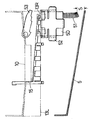
具体的には、例えばパチンコ機3が遊技島の左端寄り(即ち遊技島の左端又はその近傍)に位置する場合には、図7に示すように、玉返却口13として右側返却用の玉返却口13Rを選択し、玉誘導部材15の先端側を玉返却口13Rの方に向けた状態で玉返却部14に取り付け、それに伴い、玉返却管51が右側に位置するように玉計数機50を計数機取付部材52に取り付け、該計数機取付部材52を玉返却口13Rに対応する右側の取付部材係合部14cに取り付け、かつ玉整列部材53を玉返却口13Rに対応する右側の整列部材取付部14dに取り付けた状態の玉タンク装置1を設置台2に設置することにより、パチンコ玉を右側返却用の玉返却口13Rから返却することができ、その際に、玉計数機50から垂下される玉返却管51と、右側に向けて下り傾斜している玉回収樋5との隙間Sを広く取ることができるので、パチンコ玉を詰まらせることなく返却できる。   Specifically, for example, when the pachinko machine 3 is located near the left end of the amusement island (that is, the left end of the amusement island or in the vicinity thereof), as shown in FIG. The mouth counter 15 is selected, and the ball guide member 15 is attached to the ball return portion 14 with the tip side facing the ball return port 13R, and accordingly, the ball counter 50 is positioned so that the ball return pipe 51 is located on the right side. Is mounted on the counter mounting member 52, the counter mounting member 52 is mounted on the right mounting member engaging portion 14c corresponding to the ball return port 13R, and the ball alignment member 53 is aligned on the right side corresponding to the ball return port 13R. By installing the ball tank device 1 attached to the member attaching portion 14d on the installation base 2, the pachinko balls can be returned from the ball return port 13R for returning the right side. Hanging ball return tube 1, it is possible to widen the gap S between the balls collecting trough 5 that inclined downward toward the right, it can return without clogging the pachinko ball.

また、例えばパチンコ機3が遊技島の右端寄り(即ち遊技島の右端又はその近傍)に位置する場合には、図8に示すように、玉返却口13として左側返却用の玉返却口13Lを選択し、玉誘導部材15の先端側を玉返却口13Lの方に向けた状態で玉返却部14に取り付け、それに伴い、玉返却管51が左側に位置するように(即ち図7と比較して垂直軸周りに180度回転させた状態の)玉計数機50を計数機取付部材52に取り付け、該計数機取付部材52を玉返却口13Lに対応する左側の取付部材係合部14cに取り付け、かつ玉整列部材53を玉返却口13Lに対応する左側の整列部材取付部14dに取り付けた状態の玉タンク装置1を設置台2に設置することにより、パチンコ玉を左側返却用の玉返却口13Lから返却することができ、その際に、玉計数機50から垂下される玉返却管51と、左側に向けて下り傾斜している玉回収樋5との隙間Sを広く取ることができるので、パチンコ玉を詰まらせることなく返却できる。   Further, for example, when the pachinko machine 3 is located near the right end of the game island (that is, the right end of the game island or the vicinity thereof), as shown in FIG. The ball guide member 15 is attached to the ball return portion 14 with the front end side of the ball guide member 15 facing the ball return port 13L, and accordingly, the ball return tube 51 is positioned on the left side (that is, compared with FIG. 7). The ball counter 50 (rotated 180 degrees around the vertical axis) is attached to the counter attachment member 52, and the counter attachment member 52 is attached to the left attachment member engaging portion 14c corresponding to the ball return port 13L. In addition, by installing the ball tank device 1 in a state in which the ball alignment member 53 is attached to the left alignment member attachment portion 14d corresponding to the ball return port 13L on the installation base 2, the ball return port for returning the pachinko balls to the left side Return from 13L In that case, since the clearance S between the ball return pipe 51 suspended from the ball counter 50 and the ball collection basket 5 inclined downward toward the left side can be widened, the pachinko balls are clogged. It can be returned without

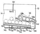
次に図9乃至図11を参照して、変形例に係るタンク部本体10’,及びそれに関連する構成について説明する。タンク部本体10’は、パチンコ機3から排出される排出玉を受け入れるものであり、図9に示すように、前記タンク部本体10と同様に、上面が開口し、平面視で横長の長方形状を呈し、正面視で皿状の底板を有する有底容器である。   Next, with reference to FIGS. 9 to 11, a tank body 10 ′ according to a modification and a configuration related thereto will be described. The tank body 10 'receives the balls discharged from the pachinko machine 3. As shown in FIG. 9, the tank body 10' has an open top surface and a horizontally long rectangular shape in plan view as shown in FIG. And a bottomed container having a dish-like bottom plate in a front view.

このタンク部本体10’は、前記タンク部本体10と比較して、前記受入部10a,切欠部10b,固定突片10c,固定突片10d,固定突片10e,弾性体板取付孔10g,前後案内溝11,及びラック12を有している一方、前記位置決め用切り込み10f,及び玉返却口13が備えられる玉返却部14を有していない。   Compared with the tank body 10, the tank body 10 ′ includes the receiving portion 10 a, the notch 10 b, the fixed protrusion 10 c, the fixed protrusion 10 d, the fixed protrusion 10 e, the elastic plate mounting hole 10 g, front and rear While having the guide groove 11 and the rack 12, it does not have the ball return portion 14 provided with the positioning cut 10f and the ball return port 13.

なおタンク部本体10’の切欠部10bにおいては、図10(a)及び図11(a)に示すように、底板が前壁よりも前方に向けて延出する態様で延出底板が設けられている。この延出底板は、タンク部本体10’に受け入れられた排出玉を、後述する玉受入領域14R’,14L’に確実に流下させるためのものである。   As shown in FIGS. 10A and 11A, the notch 10b of the tank body 10 ′ is provided with an extending bottom plate in such a manner that the bottom plate extends forward from the front wall. ing. The extended bottom plate is for surely letting the discharged balls received by the tank body 10 'flow down to the ball receiving areas 14R' and 14L 'described later.

またタンク部本体10’の前壁における切欠部10bの左右両側には、図10(a)及び図11(a)に示すように、前壁よりも前方に向けて突出する態様でシュート係合部10i’,10i’が設けられている。このシュート係合部10i’は、後述する玉返却シュート14’を取り付けるためのものであり、平面視で凹字状を呈する板材である。   Further, as shown in FIGS. 10 (a) and 11 (a), chute engagement is performed on both the left and right sides of the notch 10b on the front wall of the tank body 10 'so as to protrude forward from the front wall. Portions 10i ′ and 10i ′ are provided. This chute engaging portion 10i 'is for attaching a ball return chute 14' to be described later, and is a plate material having a concave shape in plan view.

タンク部本体10’の前方には、図9乃至図11に示すように、玉返却シュート14’が設けられている。この玉返却シュート14’は、タンク部本体10’に受け入れられた排出玉を受け入れるための玉受入領域14R’,14L’と、該排出玉を玉回収樋5に向けて返却するための玉返却口13R’,13L’を備えるものであり、該タンク部本体10’に対して着脱可能とされている。   A ball return chute 14 'is provided in front of the tank body 10' as shown in FIGS. The ball return chute 14 ′ includes ball receiving areas 14 R ′ and 14 L ′ for receiving the discharged balls received in the tank body 10 ′, and a ball return for returning the discharged balls to the ball collecting basket 5. It is provided with mouths 13R ′ and 13L ′ and is detachable from the tank body 10 ′.

この玉返却シュート14’は、タンク部本体10’の長手方向に沿って、タンク部本体10’の切欠部10bに連通する基端部から該タンク部本体10’の一方端側(図9では右側)である先端部に至る長さに形成されており、前記長手方向に平行な仕切壁14a’を有すると共に、該仕切壁14a’を境にして前後に平行な二条の誘導路15R’,15L’を有する。この誘導路15R’は、パチンコ玉を右側から返却するための右側返却用の通路であり、同様に誘導路15L’は、パチンコ玉を左側から返却するための左側返却用の通路である。   This ball return chute 14 'is arranged along the longitudinal direction of the tank body 10' from the base end communicating with the notch 10b of the tank body 10 '(see FIG. 9). Right side) and has a partition wall 14a 'parallel to the longitudinal direction, and two guide paths 15R' parallel to the front and rear with the partition wall 14a 'as a boundary. 15L ′. The guide path 15R 'is a right-hand return path for returning the pachinko balls from the right side. Similarly, the guide path 15L' is a left-hand return path for returning the pachinko balls from the left side.

この右側返却用の誘導路15R’の底板における先端部側に、右側返却用の玉返却口13R’が設けられており、同様に左側返却用の誘導路15L’の底板における先端部に、左側返却用の玉返却口13L’が設けられている。これら誘導路15R’,15L’の幅は、パチンコ玉が一つだけ通過可能な幅に形成されている。   A right return ball return port 13R ′ is provided on the front end portion of the bottom plate of the right return guide passage 15R ′, and similarly, on the left end of the bottom plate of the left return guide passage 15L ′, A ball return opening 13L ′ for return is provided. The widths of the guide paths 15R 'and 15L' are formed such that only one pachinko ball can pass through.

また右側返却用の誘導路15R’の側壁における基端部側に、右側返却用の玉受入領域14R’が設けられており、同様に左側返却用の誘導路15L’の側壁における基端部に、左側返却用の玉受入領域14L’が設けられている。この玉受入領域14R’,14L’は、ここではタンク部本体10’の切欠部10bと略等しい幅の正面視で長方形状を呈する切欠である。   Further, a ball receiving area 14R ′ for returning the right side is provided on the base end side of the side wall of the right-side return guideway 15R ′, and similarly, on the base end part of the side wall of the left-side return guideway 15L ′. A ball receiving area 14L ′ for returning the left side is provided. The ball receiving areas 14R 'and 14L' are cutouts having a rectangular shape in front view having a width substantially equal to the cutout part 10b of the tank body 10 '.

また玉返却シュート14’には、玉返却シュート14’をタンク部本体10’に取り付けるためのタンク部本体取付部の一例である本体係合爪14e’が複数設けられている。具体的には、玉返却シュート14’の前壁において、左右一対のシュート係合部10i’,10i’に対向する箇所に、左右一対の本体係合爪14e’,14e’が設けられており、同様に玉返却シュート14’の後壁において、左右一対の本体係合爪14e’,14e’が設けられている。   The ball return chute 14 'is provided with a plurality of main body engaging claws 14e' which are an example of a tank part main body attaching part for attaching the ball return chute 14 'to the tank part main body 10'. Specifically, on the front wall of the ball return chute 14 ', a pair of left and right body engaging claws 14e' and 14e 'are provided at locations facing the pair of left and right chute engaging portions 10i' and 10i '. Similarly, a pair of left and right main body engaging claws 14e 'and 14e' are provided on the rear wall of the ball return chute 14 '.

即ち、この玉返却シュート14’においては、玉受入領域14R’,14L’が複数(ここでは前後の二箇所)設けられ、該玉受入領域14R’,14L’に対応して玉受入領域14R’,14L’が設けられ、該玉受入領域14R’,14L’に対応して玉返却口13R’,13L’が設けられ、該玉受入領域14R’,14L’と玉返却口13R’,13L’をつなぐ誘導路15R’,15L’が設けられている。   That is, in this ball return chute 14 ′, a plurality of ball receiving areas 14R ′ and 14L ′ (here, two in front and rear) are provided, and the ball receiving areas 14R ′ corresponding to the ball receiving areas 14R ′ and 14L ′. , 14L ′, and ball return openings 13R ′, 13L ′ are provided corresponding to the ball receiving areas 14R ′, 14L ′. The ball receiving areas 14R ′, 14L ′ and the ball return openings 13R ′, 13L ′ are provided. Guide paths 15R ′ and 15L ′ are provided.

なお本体係合爪14e’は、ここでは前壁及び後壁から水平に向けて延出した後に曲折して下方に向けて延出する板材であり、この本体係合爪14e’がシュート係合部10i’に対して上方から係合されることにより、玉返却シュート14’がタンク部本体10’の前方に係合されて取り付けられる。   Here, the main body engaging claw 14e ′ is a plate material that extends horizontally from the front wall and the rear wall and then bends and extends downward. The main body engaging claw 14e ′ is a chute engaging member. By engaging with the portion 10i ′ from above, the ball return chute 14 ′ is engaged and attached in front of the tank body 10 ′.

また玉返却シュート14’の底板は、図10(b)及び図11(b)に示すように、玉返却シュート14’がタンク部本体10’に取り付けられた状態において、タンク部本体10’の切欠部10bから流下された排出玉が、底板上を自重により転動して玉返却口13’に向かうように、基端部側から先端部側に向けて所定の傾斜角度をもって下り傾斜して形成される。また玉返却シュート14’の底板には、複数のゴミ落とし口(図示外)が間欠状に設けられている。   Further, as shown in FIGS. 10B and 11B, the bottom plate of the ball return chute 14 ′ has a tank return body 14 ′ attached to the tank main body 10 ′. The discharged balls that have flowed down from the notch 10b roll down with a predetermined inclination angle from the base end side toward the tip end side so as to roll on the bottom plate due to their own weight toward the ball return port 13 ′. It is formed. A plurality of dust drop openings (not shown) are provided intermittently on the bottom plate of the ball return chute 14 '.

また玉返却シュート14’の仕切壁14a’は、図10(a)及び図11(a)に示すように、玉返却シュート14’がタンク部本体10’に取り付けられた状態において、タンク部本体10’に受け入れられた排出玉が、いずれか選択された玉返却口13’(例えば玉返却口13R’)に連通する玉受入領域14’(ここでは玉受入領域14R’)に受け入れられるように、即ち選択されていない玉返却口13’(例えば玉返却口13L’)に連通する玉受入領域14’(ここでは玉受入領域14L’)に受け入れられることがないように、十分な高さに形成される。   Further, the partition wall 14a ′ of the ball return chute 14 ′ has a tank portion main body in a state in which the ball return chute 14 ′ is attached to the tank portion main body 10 ′ as shown in FIGS. 10 (a) and 11 (a). The discharged balls received by 10 ′ are received by the ball receiving area 14 ′ (here, the ball receiving area 14R ′) communicating with any selected ball return opening 13 ′ (for example, the ball return opening 13R ′). That is, the height is sufficiently high so that it is not received by the ball receiving area 14 ′ (here, the ball receiving area 14 L ′) communicating with the unselected ball return opening 13 ′ (for example, the ball return opening 13 L ′). It is formed.

また玉返却シュート14’の仕切壁14a’における先端部側には、図9に示すように、整列部材取付部14d’が設けられている。この整列部材取付部14d’は、前記玉整列部材53を取り付けるためのものであり、前記整列部材取付部14dと同様の形状を呈するものである。   Further, as shown in FIG. 9, an alignment member attaching portion 14d 'is provided on the tip end side of the partition wall 14a' of the ball return chute 14 '. The alignment member attachment portion 14d 'is for attaching the ball alignment member 53, and has the same shape as the alignment member attachment portion 14d.

またタンク部本体10’の前壁が下方に向けて延設された延設前壁における左右両端側には、図10(b)及び図11(b)に示すように、取付部材係合孔10h’,10h’が設けられている。この取付部材係合孔10h’は第三の取付部の一例であって、玉返却口13’の位置に対応して、後述する計数機取付部材52’を取り付けるためのものである。   Further, as shown in FIGS. 10 (b) and 11 (b), on the left and right ends of the extended front wall in which the front wall of the tank body 10 'extends downward, the mounting member engaging hole 10h 'and 10h' are provided. The attachment member engagement hole 10h 'is an example of a third attachment portion, and is for attaching a counter attachment member 52' to be described later corresponding to the position of the ball return port 13 '.

ここで計数機取付部材52’は計数機取付部の一例であって、玉計数機50を取り付けるためのものであるが、前記計数機取付部材52と異なり、玉計数機50の背面側に取り付けられ、選択されたいずれか任意の玉返却口13’の位置に対応する取付部材係合孔10h’に対して背面側から取り付けられる。   Here, the counter mounting member 52 ′ is an example of a counter mounting portion, and is for mounting the ball counter 50. Unlike the counter mounting member 52, the counter mounting member 52 ′ is mounted on the back side of the ball counter 50. It is attached from the back side to the attachment member engagement hole 10h ′ corresponding to the position of any selected ball return port 13 ′.

以上に説明した変形例に係るタンク部本体10’を備える玉タンク装置においては、玉タンク装置の取付位置に応じて、タンク部本体10に取り付ける本体係合爪14e’を選択することで、排出玉が返却される玉返却口13’の位置(ここでは右側又は左側)が変更され、該選択されたいずれか任意の玉返却口13’の位置からパチンコ玉を振り分けて返却することができる。   In the ball tank device including the tank body 10 ′ according to the modified example described above, the body engagement claw 14e ′ attached to the tank body 10 is selected according to the attachment position of the ball tank device, thereby discharging. The position (in this case, the right side or the left side) of the ball return port 13 ′ where the balls are returned is changed, and the pachinko balls can be sorted and returned from the position of any selected ball return port 13 ′.

具体的には、例えばパチンコ機3が遊技島の左端寄り(即ち遊技島の左端又はその近傍)に位置する場合には、図10に示すように、玉返却口13’の位置として右側を選択し、切欠部10bと右側返却用の玉受入領域14R’とが連通するように、玉返却シュート14’の先端部側を右側に向けた状態でタンク部本体10’に取り付け、それに伴い、玉返却管51が右側に位置するように玉計数機50を計数機取付部材52’に取り付け、該計数機取付部材52’を右側の取付部材係合孔10h’に取り付け、かつ玉整列部材53を右側返却用の誘導路15R’の内部に出退可能なように整列部材取付部14d’に取り付けた状態の玉タンク装置を設置台2に設置することにより、パチンコ玉を右側返却用の玉返却口13R’から返却することができ、その際に、玉計数機50から垂下される玉返却管51と、右側に向けて下り傾斜している玉回収樋5との隙間Sを広く取ることができるので、パチンコ玉を詰まらせることなく返却できる。   Specifically, for example, when the pachinko machine 3 is located near the left end of the game island (that is, the left end of the game island or the vicinity thereof), the right side is selected as the position of the ball return port 13 ′ as shown in FIG. The ball return chute 14 ′ is attached to the tank body 10 ′ with the tip end side facing the right side so that the cutout portion 10b and the right return ball receiving area 14R ′ communicate with each other. The ball counter 50 is attached to the counter attachment member 52 ′ so that the return pipe 51 is located on the right side, the counter attachment member 52 ′ is attached to the right attachment member engaging hole 10h ′, and the ball alignment member 53 is attached to the counter attachment member 52 ′. By installing a ball tank device mounted on the alignment member mounting portion 14d ′ so as to be able to move in and out of the right-side return guideway 15R ′, the pachinko ball is returned to the right return ball. Return from mouth 13R ' In that case, since the clearance S between the ball return pipe 51 suspended from the ball counter 50 and the ball collection basket 5 inclined downward toward the right side can be widened, the pachinko ball Can be returned without clogging.

また、例えばパチンコ機3が遊技島の右端寄り(即ち遊技島の右端又はその近傍)に位置する場合には、図11に示すように、玉返却口13’の位置として左側を選択し、切欠部10bと左側返却用の玉受入領域14L’とが連通するように、玉返却シュート14’の先端部側を左側に向けた状態でタンク部本体10’に取り付け、それに伴い、玉返却管51が左側に位置するように(即ち図10と比較して垂直軸周りに180度回転させた状態の)玉計数機50を計数機取付部材52’に取り付け、該計数機取付部材52’を左側の取付部材係合孔10h’に取り付け、かつ玉整列部材53を左側返却用の誘導路15L’の内部に出退可能なように整列部材取付部14d’に取り付けた状態の玉タンク装置を設置台2に設置することにより、パチンコ玉を左側返却用の玉返却口13L’から返却することができ、その際に、玉計数機50から垂下される玉返却管51と、左側に向けて下り傾斜している玉回収樋5との隙間Sを広く取ることができるので、パチンコ玉を詰まらせることなく返却できる。   Further, for example, when the pachinko machine 3 is located near the right end of the game island (that is, the right end of the game island or the vicinity thereof), as shown in FIG. The ball return chute 14 ′ is attached to the tank body 10 ′ with the tip of the ball return chute 14 ′ facing left so that the portion 10 b and the ball receiving area 14 L ′ for return on the left side communicate with each other. Is mounted on the counter mounting member 52 ′ so that the counter is located on the left side (ie, rotated 180 degrees around the vertical axis compared to FIG. 10). The ball tank device is installed in the mounting member engaging hole 10h ′ and mounted in the alignment member mounting portion 14d ′ so that the ball alignment member 53 can be moved into and out of the left return guide path 15L ′. By installing on stand 2 The pachinko ball can be returned from the ball return port 13L ′ for returning the left side. At that time, the ball return pipe 51 suspended from the ball counter 50 and the ball collection basket 5 inclined downward toward the left side. Can be widened, so it can be returned without clogging pachinko balls.

[1−2.内部支持脚の構成]
内部支持脚20は、図2及び図12に示すように、タンク部本体10(又は10’)を支持する支持脚を構成するものであり、ここでは上面及び下面が開口した矩形の中空筒である。内部支持脚20の上部における左右の周壁には、各二つずつのL字状の弾性突片20aが、外向きに突設されている。また内部支持脚20の上部における左右の周壁において、各弾性突片20a,20aの間の部分が、板状の可撓片20bとされている。また内部支持脚20の左右の周壁において、下縁から上方に向けて形成された二本の溝の間の部分が、板状の可撓片20cとされている。さらに内部支持脚20の上部における前後の周壁には、板状の載置支持片24が、水平外向きに突設されている。
[1-2. Configuration of internal support legs]
As shown in FIGS. 2 and 12, the internal support leg 20 constitutes a support leg that supports the tank body 10 (or 10 ′). Here, the internal support leg 20 is a rectangular hollow cylinder having an open upper surface and a lower surface. is there. Two L-shaped elastic protrusions 20 a are provided on the left and right peripheral walls at the top of the internal support leg 20 so as to protrude outward. Further, on the left and right peripheral walls in the upper part of the internal support leg 20, a portion between the elastic protrusions 20a and 20a is a plate-like flexible piece 20b. Further, in the left and right peripheral walls of the internal support leg 20, a portion between two grooves formed upward from the lower edge is a plate-like flexible piece 20c. Further, on the front and rear peripheral walls at the upper part of the internal support leg 20, plate-like placement support pieces 24 are provided so as to project horizontally outward.

弾性突片20a及び可撓片20bには、タンク部本体10(又は10’)の前後方向の移動を司る前後係合部が設けられている。具体的には、弾性突片20aの先端部に、前後係合部を構成する正面視で三角形状の前後案内爪21が、前後案内溝11に係合するように水平外向きに突設されている。この前後案内爪21には、後述する前後方向移動用の目印81も刻設されている。また可撓片20bの先端部に、前後係合部を構成する平面視で王冠状の係合爪22が、ラック12に係合するように水平外向きに突設されている。   The elastic projection piece 20a and the flexible piece 20b are provided with a front / rear engaging portion for controlling the movement of the tank body 10 (or 10 ') in the front / rear direction. Specifically, a front and rear guide claw 21 having a triangular shape in front view that constitutes the front and rear engaging portion is provided at the front end of the elastic protruding piece 20 a so as to protrude horizontally outward so as to engage with the front and rear guide groove 11. ing. The front / rear guide claw 21 is also provided with a mark 81 for moving in the front / rear direction, which will be described later. In addition, a crown-like engagement claw 22 in a plan view that constitutes the front-rear engagement portion is provided on the distal end portion of the flexible piece 20 b so as to protrude horizontally outward so as to engage with the rack 12.

可撓片20cには、タンク部本体10(又は10’)の上下方向の移動を司る上下係合部が設けられている。具体的には、可撓片20cの先端部に、上下係合部を構成する上下係合案内爪23が、後述する上下係合案内溝33に係合するように水平外向きに突設されている。この上下係合案内爪23は、後述する幅広溝33aに係合する形状、例えば基端側の幅広部23aと先端側の幅狭部23bが平面視で凸状に形成されてなる。この上下係合案内爪23には、後述する上下方向移動用の目印71も刻設されている。なお載置支持片24は、固定突片10eを載置支持するものである。   The flexible piece 20c is provided with a vertical engagement portion that controls the vertical movement of the tank body 10 (or 10 '). Specifically, a vertical engagement guide claw 23 that constitutes a vertical engagement portion protrudes horizontally at the tip of the flexible piece 20c so as to engage with a vertical engagement guide groove 33 described later. ing. The vertical engagement guide claw 23 has a shape that engages with a wide groove 33a to be described later, for example, a base-side wide portion 23a and a distal-side narrow portion 23b are formed in a convex shape in plan view. The vertical engagement guide claw 23 is also engraved with a mark 71 for vertical movement described later. The placement support piece 24 is for placing and supporting the fixed protrusion 10e.

[1−3.外部支持脚の構成]
外部支持脚30は、図2及び図13に示すように、組立時に内部支持脚20に外嵌されて、タンク部本体10(又は10’)を支持する支持脚を構成するものであり、ここでは上面が開口し正面視で凸状の上げ底を有する矩形の有底筒である。
[1-3. Configuration of external support legs]
As shown in FIGS. 2 and 13, the external support leg 30 is externally fitted to the internal support leg 20 at the time of assembly, and constitutes a support leg that supports the tank body 10 (or 10 ′). Then, it is a rectangular bottomed cylinder having an open top surface and a raised bottom that is convex in a front view.

外部支持脚30の下部には、タンク部本体10(又は10’)の左右方向の移動を司る左右係合部が設けられている。具体的には、外部支持脚30の前後の周壁において、下縁から上方に向けて形成された二本の溝の間の部分が、さらに鉛直下向きに延設されて、板状の弾性突片30aとされており、この弾性突片30aの先端部に、左右係合部を構成する側面視で逆三角形状の左右案内爪31が、後述する左右案内溝41に係合するように水平外向きに突設されている。なお外部支持脚30の前後の周壁の中央には、後述する左右方向移動用の目印61が刻設されている。また外部支持脚30の下面の中央に、一対の湾曲板状の挟持片32aが、左右方向に亘って鉛直下向きに突設されており、この挟持片32aが、左右係合部を構成する嵌合凹部32とされている。   A left and right engaging portion that controls the movement of the tank body 10 (or 10 ′) in the left and right direction is provided at the lower portion of the external support leg 30. Specifically, on the front and rear peripheral walls of the external support leg 30, a portion between two grooves formed upward from the lower edge is further extended vertically downward to form a plate-like elastic protruding piece. The left and right guide claws 31 having an inverted triangle shape when viewed from the side constituting the left and right engaging portions are engaged with the left and right guide grooves 41, which will be described later. Projected in the direction. In the center of the peripheral wall before and after the external support leg 30, a mark 61 for lateral movement described later is formed. In addition, a pair of curved plate-like sandwiching pieces 32a projecting vertically downward in the left-right direction at the center of the lower surface of the external support leg 30, and this sandwiching piece 32a is a fitting that forms a left-right engaging portion. A joint recess 32 is provided.

外部支持脚30の側部には、タンク部本体10(又は10’)の上下方向の移動を司る上下被係合部が上下方向に亘って設けられている。具体的には、外部支持脚30の左右の周壁に、上下被係合部を構成する上下係合案内溝33が、上下方向で所定の範囲に亘って垂直に穿設されている。この上下係合案内溝33は、複数(ここでは三箇所)の幅広溝33aと複数(ここでは二箇所)の幅狭溝33bが立面視で交互に連設された形状(ここでは「王」字状)に形成されてなる。なお上下係合案内溝33の近傍において、外部支持脚30の左右の周壁には、後述する上下方向移動用の目盛70が、上下方向に亘って刻設されている。   On the side portion of the external support leg 30, a vertically engaged portion that controls the vertical movement of the tank body 10 (or 10 ′) is provided in the vertical direction. Specifically, upper and lower engagement guide grooves 33 constituting the upper and lower engaged portions are formed in the left and right peripheral walls of the external support leg 30 vertically in a predetermined range in the vertical direction. The vertical engagement guide groove 33 has a shape in which a plurality (three in this case) wide grooves 33a and a plurality (two in this case) narrow grooves 33b are alternately arranged in an elevational view (here, “king” "Shaped"). In addition, in the vicinity of the vertical engagement guide groove 33, a scale 70 for moving in the vertical direction, which will be described later, is engraved on the left and right peripheral walls of the external support leg 30 in the vertical direction.

[1−4.支持土台の構成]
支持土台40は、図2及び図14乃至図16に示すように、支持脚(即ち内部支持脚20及び外部支持脚30)を支持するものであり、ここでは上面のうち中央のみが窪んだ凹状の底を有する矩形の有底箱である。支持土台40の左右における上面には、支持土台40を設置台2に取り付けるためのビスを挿通するビス孔40aが穿設されている。
[1-4. Structure of support base]
As shown in FIG. 2 and FIGS. 14 to 16, the support base 40 supports the support legs (that is, the internal support legs 20 and the external support legs 30). It is a rectangular bottomed box having a bottom. Screw holes 40a are formed in the upper surfaces of the support base 40 on the left and right sides, and through which screws for attaching the support base 40 to the installation base 2 are inserted.

支持土台40の上面には、タンク部本体10(又は10’)の左右方向の移動を司る左右被係合部が左右方向に亘って設けられている。具体的には、支持土台40の前後における上面に、左右被係合部を構成する平面視で長方形状の左右案内溝41が、左右方向で所定の範囲に亘って水平に穿設されている。また支持土台40の中央における底面上に、左右被係合部を構成する嵌合凸部42が、左右方向に亘って間欠状に突設されている。この嵌合凸部42は、支持土台40の底面から鉛直上向きに間欠状に一定間隔で突設される複数(ここでは九箇所)の突起42aと、それら突起42a同士の間をつなぐ接続片42bからなる。なお左右案内溝41及び嵌合凸部42の近傍において、支持土台40の前後における上面には、後述する左右方向移動用の目盛60が、左右方向に亘って刻設されている。   On the upper surface of the support base 40, left and right engaged portions for controlling the movement of the tank body 10 (or 10 ') in the left-right direction are provided in the left-right direction. Specifically, left and right guide grooves 41 that are rectangular in a plan view that constitute the left and right engaged portions are formed horizontally on a top surface of the support base 40 in the front and rear directions over a predetermined range in the left and right direction. . Further, on the bottom surface at the center of the support base 40, a fitting convex portion 42 constituting a left and right engaged portion is provided so as to protrude intermittently in the left and right direction. The fitting protrusions 42 are a plurality of (in this case, nine) protrusions 42a that protrude intermittently from the bottom surface of the support base 40 at regular intervals and a connecting piece 42b that connects the protrusions 42a. Consists of. In the vicinity of the left and right guide grooves 41 and the fitting convex portion 42, a scale 60 for moving in the left and right direction, which will be described later, is engraved on the upper surface of the support base 40 in the left and right direction.

[1−5.目盛及び目印の構成]
玉タンク装置1は、上記の如く、タンク部本体10(又は10’)の取付位置を把握可能な目盛60,70,80、及びその目盛を指す目印61,71,81を有する。なお、これら目盛及び目印は、設置台2からパチンコ機3を取り外した際に、タンク部本体10(又は10’)を移動して取付位置を調節する作業者が視認できる位置に設けられるのが好ましい。
[1-5. Structure of scale and mark]
As described above, the ball tank apparatus 1 has the scales 60, 70, 80 that can grasp the mounting position of the tank body 10 (or 10 ′), and marks 61, 71, 81 indicating the scales. In addition, when these scales and marks are removed from the installation table 2, the scales and the marks are provided at positions where an operator who moves the tank body 10 (or 10 ′) and adjusts the mounting position can visually recognize it. preferable.

左右方向移動用の目盛60は、図17(a)に示すように、支持土台40に表示され、タンク部本体10(又は10’)の左右方向の取付位置を把握可能なものである。具体的には、目盛60は、左右案内溝41及び嵌合凸部42の近傍において、支持土台40の前後における上面に、左右方向に亘って刻設されている。この目盛60は、ここでは複数の突起42aの位置に対応するように、左側から順に「+4,+3,+2,+1,0,−1,−2,−3,−4」という9段階の数字が表示されており、タンク部本体10(又は10’)が移動できる範囲の中心位置(ここでは「0」)を把握可能な形式で表示されている。   As shown in FIG. 17A, the scale 60 for moving in the left-right direction is displayed on the support base 40 and can grasp the mounting position in the left-right direction of the tank body 10 (or 10 '). Specifically, the scale 60 is engraved on the upper surface of the support base 40 in the vicinity of the left and right guide grooves 41 and the fitting projections 42 in the left-right direction. The scale 60 is a nine-step number “+4, +3, +2, +1, 0, −1, −2, −3, −4” in order from the left side so as to correspond to the positions of the plurality of protrusions 42a. Is displayed in a format in which the center position (here, “0”) of the range in which the tank body 10 (or 10 ′) can move can be grasped.

一方、左右方向移動用の目印61は、図13及び図17(a)に示すように、外部支持脚30に表示され、目盛60を指すものである。具体的には、目印61は、外部支持脚30の前後の周壁の中央に、下向きの矢印として刻設されている。   On the other hand, the mark 61 for moving in the left-right direction is displayed on the external support leg 30 and indicates the scale 60 as shown in FIGS. Specifically, the mark 61 is engraved as a downward arrow at the center of the peripheral wall before and after the external support leg 30.

上下方向移動用の目盛70は、図13及び図17(a)に示すように、外部支持脚30に表示され、タンク部本体10(又は10’)の上下方向の取付位置を把握可能なものである。具体的には、目盛70は、上下係合案内溝33の近傍において、外部支持脚30の左右の周壁に、上下方向に亘って刻設されている。この目盛70は、ここでは複数の幅広溝33aの位置に対応するように、上側から順に「上,中,下」という3段階の漢字が表示されており、タンク部本体10(又は10’)が移動できる範囲の中心位置(ここでは「中」)を把握可能な形式で表示されている。   As shown in FIGS. 13 and 17A, the scale 70 for moving in the vertical direction is displayed on the external support leg 30 and can grasp the vertical mounting position of the tank body 10 (or 10 ′). It is. Specifically, the scale 70 is engraved in the vertical direction on the left and right peripheral walls of the external support leg 30 in the vicinity of the vertical engagement guide groove 33. In this scale 70, three levels of Chinese characters “upper, middle, lower” are displayed in order from the upper side so as to correspond to the positions of the plurality of wide grooves 33a, and the tank body 10 (or 10 ′). Is displayed in a format in which the center position (in this case, “middle”) of the movable range can be grasped.

一方、上下方向移動用の目印71は、図12及び図17(a)に示すように、内部支持脚20に表示され、目盛70を指すものである。具体的には、目印71は、上下係合案内爪23に、横向きの矢印として刻設されている。なお上下係合案内爪23自体を目印として用い、目印71を省略することも可能である。   On the other hand, the mark 71 for moving in the vertical direction is displayed on the internal support leg 20 and indicates the scale 70 as shown in FIGS. Specifically, the mark 71 is engraved on the vertical engagement guide claw 23 as a horizontal arrow. It is also possible to use the vertical engagement guide claw 23 itself as a mark and omit the mark 71.

前後方向移動用の目盛80は、図17(b)に示すように、タンク部本体10(又は10’)に表示され、タンク部本体10(又は10’)の前後方向の取付位置を把握可能なものである。具体的には、目盛80は、タンク部本体10(又は10’)の下面に突設され、前後案内溝11が形成された固定突片10cの下側に、前後方向に亘って水平外向きに刻設されている。この目盛80は、ラック12の任意の歯の位置に対応するように、後側から順に「A,B,C…,J,K,L」という12段階のアルファベット文字が表示されている。   As shown in FIG. 17B, the scale 80 for moving in the front-rear direction is displayed on the tank unit body 10 (or 10 ′) and can grasp the mounting position in the front-rear direction of the tank unit body 10 (or 10 ′). Is something. Specifically, the scale 80 protrudes on the lower surface of the tank body 10 (or 10 '), and is horizontally outward in the front-rear direction on the lower side of the fixed protrusion 10c in which the front-rear guide groove 11 is formed. It is carved in. The scale 80 displays 12 alphabetic characters “A, B, C..., J, K, L” in order from the rear so as to correspond to the position of an arbitrary tooth on the rack 12.

一方、前後方向移動用の目印81は、図12及び図17(b)に示すように、内部支持脚20に表示され、目盛80を指すものである。具体的には、目印81は、パチンコ機3側の前後案内爪21に、下向きの矢印として刻設されている。   On the other hand, the mark 81 for moving in the front-rear direction is displayed on the internal support leg 20 and indicates the scale 80 as shown in FIGS. Specifically, the mark 81 is engraved as a downward arrow on the front and rear guide claws 21 on the pachinko machine 3 side.

作業者はこれら目盛60,70,80、及び目印61,71,81が有ることにより、タンク部本体10(又は10’)の取付位置を容易かつ正確に把握できる。またタンク部本体10(又は10’)を、これら目盛及び目印に基づいて(見ながら,触れながら等)所定方向に移動することにより、移動作業(位置調節)を行うにあたり、タンク部本体10(又は10’)の取付位置を容易かつ正確に把握でき、従って作業に必要以上の時間を要しない。なお目盛60,70は、必ずしも中心位置を把握可能な形式で表示される必要はなく、逆に目盛80は、中心位置を把握可能な形式で表示されるものでも良い。   By having these scales 60, 70, 80 and marks 61, 71, 81, the operator can easily and accurately grasp the mounting position of the tank body 10 (or 10 ′). Further, the tank unit body 10 (or 10 ') is moved in a predetermined direction based on these scales and marks (while viewing, touching, etc.), so that the tank unit body 10 ( Alternatively, the mounting position 10 ') can be easily and accurately grasped, and therefore, the work does not require more time than necessary. The scales 60 and 70 do not necessarily need to be displayed in a format that allows the center position to be grasped. Conversely, the scale 80 may be displayed in a form that allows the center position to be grasped.

[1−6.玉タンク装置の組立]
玉タンク装置1は、前記各構成要素が以下のように組み立てられて構成される。
[1-6. Assembly of ball tank device]
The ball tank apparatus 1 is configured by assembling the respective components as follows.

まず支持土台40と外部支持脚30とは、図16に示すように、支持土台40に対して外部支持脚30を押し込むと、前後の弾性突片30aが内向きに撓んだ後に元位置に復帰して、左右案内爪31が左右案内溝41に係合すると共に、嵌合凹部32が嵌合凸部42に嵌合する。これにより、支持土台40に外部支持脚30が載置支持され、上下方向及び前後方向の移動を拘束しつつ左右方向に移動可能なように、両者が組み立てられる。   First, as shown in FIG. 16, when the external support leg 30 is pushed into the support base 40, the support base 40 and the external support leg 30 return to the original position after the front and rear elastic protrusions 30a are bent inward. Returning, the left and right guide claws 31 engage with the left and right guide grooves 41, and the fitting recess 32 fits into the fitting protrusion 42. Thereby, the external support legs 30 are placed and supported on the support base 40, and both are assembled so as to be movable in the left-right direction while restraining the movement in the up-down direction and the front-rear direction.

また外部支持脚30と内部支持脚20とは、図15に示すように、左右の可撓片20cを内向きに撓ませた状態で、外部支持脚30に対して内部支持脚20を押し込むと、左右の可撓片20cが元位置に復帰して、上下係合案内爪23の幅広部23aが上下係合案内溝33の幅広溝33aに係合する。これにより、外部支持脚30が内部支持脚20に外嵌され、左右方向及び前後方向の移動を拘束しつつ上下方向に移動可能なように、両者が組み立てられる。   Further, as shown in FIG. 15, when the left and right flexible pieces 20 c are bent inward, the external support legs 30 and the internal support legs 20 are pushed into the external support legs 30. The left and right flexible pieces 20c return to their original positions, and the wide portion 23a of the vertical engagement guide claw 23 engages with the wide groove 33a of the vertical engagement guide groove 33. As a result, the outer support leg 30 is externally fitted to the inner support leg 20, and both are assembled so as to be movable in the vertical direction while restraining the movement in the left-right direction and the front-rear direction.

また内部支持脚20とタンク部本体10(又は10’)とは、図15に示すように、タンク部本体10(又は10’)に対して内部支持脚20を押し込むと、左右の弾性突片20aが内向きに撓んだ後に元位置に復帰して、前後案内爪21が前後案内溝11に係合すると共に、係合爪22がラック12に係合する。これにより、内部支持脚20にタンク部本体10(又は10’)が載置支持され、左右方向及び上下方向の移動を拘束しつつ前後方向に移動可能なように、両者が組み立てられる。   Further, as shown in FIG. 15, the internal support leg 20 and the tank body 10 (or 10 ′) are elastic left and right elastic pieces when the internal support leg 20 is pushed into the tank body 10 (or 10 ′). After 20a bends inward, it returns to its original position, the front and rear guide claws 21 engage with the front and rear guide grooves 11, and the engagement claws 22 engage with the rack 12. Accordingly, the tank body 10 (or 10 ') is placed and supported on the internal support leg 20, and both are assembled so as to be movable in the front-rear direction while restricting the movement in the left-right direction and the up-down direction.

さらにタンク部本体10を備える玉タンク装置1においては、図7又は図8に示すように、選択されたいずれか任意の玉返却口13R又は13Lに対応する態様で、玉誘導部材15,玉計数機50が取り付けられた計数機取付部材52,及び玉整列部材53がそれぞれ取り付けられ、また変形例に係るタンク部本体10’を備える玉タンク装置においては、図10又は図11に示すように、選択されたいずれか任意の玉返却口13’の位置に対応する態様で、玉返却シュート14’,玉計数機50が取り付けられた計数機取付部材52’,及び玉整列部材53がそれぞれ取り付けられる。   Furthermore, in the ball tank apparatus 1 provided with the tank part main body 10, as shown in FIG. 7 or FIG. 8, it is the aspect corresponding to any arbitrary ball | bowl return port 13R or 13L selected, and the ball | bowl guide member 15, ball | bowl count In the ball tank apparatus to which the counter mounting member 52 to which the machine 50 is attached and the ball alignment member 53 are respectively attached and the tank unit body 10 ′ according to the modification is provided, as shown in FIG. 10 or FIG. The ball return chute 14 ′, the counter mounting member 52 ′ to which the ball counter 50 is mounted, and the ball aligning member 53 are mounted in a manner corresponding to the position of any selected ball return port 13 ′. .

以上のようにして組み立てられた玉タンク装置1は、タンク部本体10(又は10’)自体の位置調節が行われた上で、支持土台40がビス等で固定されることにより、設置台2に取り付けられる。なお前記各構成要素を組み立てる順序は任意である。また玉タンク装置1の分解は組立と逆の手順で行えば良い。この玉タンク装置1においては各部品が独立しているため、各部品のメンテナンスや部品交換を容易に行うことができる。   The ball tank apparatus 1 assembled as described above is installed on the installation base 2 by adjusting the position of the tank body 10 (or 10 ') itself and fixing the support base 40 with screws or the like. Attached to. In addition, the order which assembles each said component is arbitrary. The ball tank device 1 may be disassembled in the reverse order of assembly. Since each component is independent in this ball tank apparatus 1, maintenance of each component and component replacement can be performed easily.

なお各部品は、図示の如く、係合部がある方よりも被係合部がある方が長く、即ち前後の奥行きにおいて内部支持脚20よりもタンク部本体10(又は10’)の方が長く、左右の幅において外部支持脚30よりも支持土台40の方が長く構成されていれば良く、他の寸法は任意である。   As shown in the figure, each part has a longer engagement portion than an engagement portion, that is, the tank body 10 (or 10 ′) is longer than the internal support leg 20 in the front and rear depths. It is sufficient that the support base 40 is longer than the external support leg 30 in the left and right widths, and other dimensions are arbitrary.

[2.玉タンク装置の作用]
次に、本発明に係る玉タンク装置1の作用について説明する。なお、以下においては、まずタンク部本体10(又は10’)の位置調節について説明し、次に排出玉の受入及び返却について説明を行う。
[2. Action of ball tank device]
Next, the operation of the ball tank apparatus 1 according to the present invention will be described. In the following, the position adjustment of the tank body 10 (or 10 ') will be described first, and then the receiving and returning of the discharged balls will be described.

[2−1.タンク部本体の位置調節]
まずタンク部本体10(又は10’)の左右方向の位置調節は、主に図14(補助的に図15)に示すように、支持土台40に対して外部支持脚30を移動し、左右被係合部に対して左右係合部の係合位置を変更することにより行われる。具体的には、作業者が、外部支持脚30を左方向又は右方向に押動すると、挟持片32aが外向きに撓んで突起42aから外れ、挟持片32aが接続片42bを挟持しながら外部支持脚30が移動し、挟持片32aが所望の位置にある突起42aに嵌合する。
[2-1. Adjustment of tank body position]
First, the horizontal adjustment of the tank body 10 (or 10 ') is performed by moving the external support leg 30 with respect to the support base 40 as shown mainly in FIG. This is done by changing the engagement position of the left and right engagement portions with respect to the engagement portion. Specifically, when the operator pushes the external support leg 30 leftward or rightward, the sandwiching piece 32a bends outward and comes off the projection 42a, and the sandwiching piece 32a holds the connection piece 42b while holding the connection piece 42b. The support leg 30 moves, and the clamping piece 32a is fitted to the protrusion 42a at a desired position.

即ち嵌合凹部32が間欠状に突設された複数の嵌合凸部42に嵌合することにより、外部支持脚30が支持土台40に固定されるので、段階的に、左右方向の位置調節が行われる。またこのとき、左右案内爪31が左右案内溝41の内部を摺動しながら外部支持脚30が移動するので、所定の範囲内で、他の方向にぶれることなく、左右方向の位置調節が行われる。さらに作業者が、左右方向移動用の目盛60及び目印61を見ながら移動作業を行うことにより、タンク部本体10(又は10’)の取付位置を把握しながら位置調節が行われる。   That is, since the outer support leg 30 is fixed to the support base 40 by fitting the fitting recesses 32 into the plurality of fitting projections 42 projecting intermittently, the position adjustment in the left-right direction is gradually performed. Is done. At this time, since the outer support leg 30 moves while the left and right guide claws 31 slide inside the left and right guide grooves 41, the position adjustment in the left and right direction is performed within a predetermined range without shaking in the other direction. Is called. Further, when the operator performs the moving operation while looking at the scale 60 and the mark 61 for moving in the left-right direction, the position is adjusted while grasping the mounting position of the tank body 10 (or 10 ').

またタンク部本体10(又は10’)の上下方向の位置調節は、主に図15(補助的に図16)に示すように、外部支持脚30に対して内部支持脚20を移動し、上下被係合部に対して上下係合部の係合位置を変更することにより行われる。具体的には、作業者が、幅狭部23bを摘んで左右の可撓片20cを内向きに撓ませると(仮想線参照)、幅広部23aが幅広溝33aから外れ、内部支持脚20を上方向又は下方向に移動すると、幅狭部23bが幅狭溝33bの内部を摺動しながら内部支持脚20が移動し、所望の位置で幅狭部23bの摘みを放すと、左右の可撓片20cが元位置に復帰して(実線参照)、幅広部23aが幅広溝33aに係合する。   Further, the vertical position adjustment of the tank body 10 (or 10 ') is mainly performed by moving the internal support leg 20 with respect to the external support leg 30 as shown in FIG. This is done by changing the engaging position of the upper and lower engaging portions with respect to the engaged portion. Specifically, when the operator picks the narrow portion 23b and bends the left and right flexible pieces 20c inwardly (see the phantom line), the wide portion 23a is disengaged from the wide groove 33a, and the internal support leg 20 is removed. When moving upward or downward, the inner support leg 20 moves while the narrow portion 23b slides inside the narrow groove 33b. The bending piece 20c returns to the original position (see the solid line), and the wide portion 23a engages with the wide groove 33a.

即ち突出状態にある上下係合案内爪23の幅広部23aが上下係合案内溝33の幅広溝33aに係合することにより、内部支持脚20が外部支持脚30に固定されるので、段階的に、上下方向の位置調節が行われる。またこのとき、上下係合案内爪23が上下係合案内溝33の内部を摺動しながら内部支持脚20が移動するので、所定の範囲内で、他の方向にぶれることなく、上下方向の位置調節が行われる。さらに作業者が、上下方向移動用の目盛70及び目印71を見ながら移動作業を行うことにより、タンク部本体10(又は10’)の取付位置を把握しながら位置調節が行われる。   That is, the wide support portion 23a of the vertically engaged guide claw 23 in the protruding state engages with the wide groove 33a of the vertically engaged guide groove 33, so that the internal support leg 20 is fixed to the external support leg 30. In addition, the vertical position adjustment is performed. At this time, the inner support leg 20 moves while the upper and lower engagement guide claws 23 slide in the upper and lower engagement guide grooves 33, so that the upper and lower engagement guide claws 23 do not move in the other direction within a predetermined range. Position adjustment is performed. Further, when the operator performs the moving operation while looking at the scale 70 and the mark 71 for moving in the vertical direction, the position is adjusted while grasping the mounting position of the tank body 10 (or 10 ').

さらにタンク部本体10(又は10’)の前後方向の位置調節は、主に図16(補助的に図14)に示すように、内部支持脚20に対してタンク部本体10(又は10’)を移動し、前後係合部に対して前後被係合部の係合位置を変更することにより行われる。具体的には、作業者が、タンク部本体10(又は10’)を前方向又は後方向に押動すると、可撓片20bが内向きに撓んで係合爪22がラック12の歯から外れ、係合爪22がラック12の歯に順次係合しながらタンク部本体10(又は10’)が移動し、係合爪22が所望の位置にあるラック12の歯に係合する。   Further, the position adjustment of the tank body 10 (or 10 ′) in the front-rear direction is mainly performed as shown in FIG. 16 (supplementally FIG. 14) with respect to the internal support leg 20. And the engagement position of the front / rear engaged portion is changed with respect to the front / rear engaging portion. Specifically, when the worker pushes the tank body 10 (or 10 ′) forward or backward, the flexible piece 20b bends inward and the engaging claw 22 is disengaged from the teeth of the rack 12. The tank body 10 (or 10 ') moves while the engaging claws 22 are sequentially engaged with the teeth of the rack 12, and the engaging claws 22 are engaged with the teeth of the rack 12 at a desired position.

即ち係合爪22が鋸歯状のラック12の歯に係合しながらタンク部本体10(又は10’)が移動するので、段階的に、前後方向の位置調節が行われる。なおラック12の歯が等辺山形状に形成されてなるので、前後いずれの方向にも容易にタンク部本体10(又は10’)を位置調節できる。またこのとき、前後案内爪21が前後案内溝11の内部を摺動しながらタンク部本体10(又は10’)が移動するので、所定の範囲内で、他の方向にぶれることなく、前後方向の位置調節が行われる。さらに作業者が、前後方向移動用の目盛80及び目印81を見ながら移動作業を行うことにより、タンク部本体10(又は10’)の取付位置を把握しながら位置調節が行われる。   That is, since the tank main body 10 (or 10 ') moves while the engaging claw 22 engages with the teeth of the sawtooth rack 12, the position adjustment in the front-rear direction is performed stepwise. In addition, since the teeth of the rack 12 are formed in an equilateral mountain shape, the position of the tank body 10 (or 10 ') can be easily adjusted in any of the front and rear directions. At this time, the tank body 10 (or 10 ') moves while the front / rear guide claw 21 slides in the front / rear guide groove 11, so that the front / rear direction does not shake in the other direction within a predetermined range. The position is adjusted. Further, when the operator performs the moving operation while looking at the scale 80 and the mark 81 for moving in the front-rear direction, the position is adjusted while grasping the mounting position of the tank body 10 (or 10 ').

このような操作により、作業者は、玉タンク装置1を設置台2に最初に取り付けたり、設置台に取り付けられていたパチンコ機3を異なるメーカーのものに交換する場合に、図14乃至図16に示すように、タンク部本体10(又は10’)自体を最大で仮想線の位置まで移動可能であり、玉排出口4の位置に合わせて左右方向,上下方向,及び前後方向の三方向をそれぞれ独立して容易に位置調節できる。このとき目盛60,70,80及び目印61,71,81に基づいて(見ながら,触れながら等)作業を行えば、所望の取付位置を容易かつ正確に把握できる。   By such an operation, when the worker first attaches the ball tank apparatus 1 to the installation base 2 or replaces the pachinko machine 3 attached to the installation base with one of a different manufacturer, FIG. 14 to FIG. As shown in FIG. 4, the tank body 10 (or 10 ′) itself can be moved to the position of the imaginary line at the maximum. Each position can be easily adjusted independently. At this time, if an operation is performed based on the scales 60, 70, 80 and the marks 61, 71, 81 (while looking, touching, etc.), a desired mounting position can be easily and accurately grasped.

[2−2.排出玉の受入及び返却]
上記の如く、タンク部本体10(又は10’)自体の位置が調節され、また図1に示すように、設置台2に取り付けられた玉タンク装置1においては、パチンコ機3の玉排出口4から落下排出されるパチンコ玉(即ち排出玉)がタンク部本体10(又は10’)により受け入れられる。ここでタンク部本体10(又は10’)の内部底面は、タンク部本体10(又は10’)における端部から中央部に向かう方向及び後部から前部に向かう方向に皿状に下り傾斜しているので、受入部10aに受け入れられたパチンコ玉は自重によって転動し、切欠部10bに向けてスムーズに誘導される。
[2-2. Acceptance and return of discharged balls]
As described above, the position of the tank body 10 (or 10 ′) itself is adjusted, and as shown in FIG. 1, in the ball tank device 1 attached to the installation base 2, the ball discharge port 4 of the pachinko machine 3 is used. Pachinko balls that are dropped and discharged from the tank (that is, discharged balls) are received by the tank body 10 (or 10 '). Here, the inner bottom surface of the tank body 10 (or 10 ') is inclined downward in a dish shape in the direction from the end to the center of the tank body 10 (or 10') and in the direction from the rear to the front. Therefore, the pachinko balls received by the receiving part 10a roll by their own weight and are smoothly guided toward the notch part 10b.

ここで図7に示すように、タンク部本体10を備える玉タンク装置1で右側返却用の玉返却口13Rが選択されている場合には、切欠部10bから流下されたパチンコ玉は、玉返却部14の前壁及び後壁に規制されながら、玉誘導部材15の傾斜部15b上を自重によって転動して玉整列部材53の部位に誘導され、後述する玉整列部材53の作用によって一列に整列されて、玉返却口13Rから返却される。なお選択されていない左側返却用の玉返却口13Lに向かう方向は、起立部15aによって閉鎖されているので、切欠部10bから流下されたパチンコ玉が該玉返却口13Lに向かうことはない。また図6に示すように、パチンコ玉に付着しているゴミは、支持部15cの隙間及びゴミ落とし口14bを通過して落下する。   Here, as shown in FIG. 7, when the ball return port 13 </ b> R for the right return is selected in the ball tank device 1 including the tank body 10, the pachinko balls that have flowed down from the notch 10 b are returned as balls. While being regulated by the front wall and the rear wall of the portion 14, it rolls on the inclined portion 15 b of the ball guiding member 15 by its own weight and is guided to the portion of the ball alignment member 53, and is aligned in a row by the action of the ball alignment member 53 described later. Arranged and returned from the ball return opening 13R. In addition, since the direction which goes to the ball return opening 13L for the left side return which is not selected is closed by the standing part 15a, the pachinko ball which flowed down from the notch part 10b does not go to the ball return opening 13L. Moreover, as shown in FIG. 6, the dust adhering to the pachinko ball falls through the gap of the support portion 15c and the dust drop opening 14b.

また図8に示すように、タンク部本体10を備える玉タンク装置1で左側返却用の玉返却口13Lが選択されている場合には、切欠部10bから流下されたパチンコ玉は、玉返却部14の前壁及び後壁に規制されながら、玉誘導部材15の傾斜部15b上を自重によって転動して玉整列部材53の部位に誘導され、後述する玉整列部材53の作用によって一列に整列されて、玉返却口13Lから返却される。なお選択されていない右側返却用の玉返却口13Rに向かう方向は、起立部15aによって閉鎖されているので、切欠部10bから流下されたパチンコ玉が該玉返却口13Rに向かうことはない。また図6に示すように、パチンコ玉に付着しているゴミは、支持部15cの隙間及びゴミ落とし口14bを通過して落下する。   Moreover, as shown in FIG. 8, when the ball return port 13L for left side return is selected with the ball tank apparatus 1 provided with the tank part main body 10, the pachinko ball flowed down from the notch part 10b is a ball return part. While being regulated by the front wall 14 and the rear wall 14, it rolls by its own weight on the inclined portion 15 b of the ball guide member 15 and is guided to the portion of the ball alignment member 53, and is aligned in a row by the action of the ball alignment member 53 described later. And returned from the ball return opening 13L. In addition, since the direction which goes to the ball return port 13R for the right side return which is not selected is closed by the standing part 15a, the pachinko ball which flowed down from the notch part 10b does not go to this ball return port 13R. Moreover, as shown in FIG. 6, the dust adhering to the pachinko ball falls through the gap of the support portion 15c and the dust drop opening 14b.

一方、図10に示すように、変形例に係るタンク部本体10’を備える玉タンク装置で玉返却口13’の位置として右側が選択されている場合には、切欠部10bから流下されたパチンコ玉は、右側返却用の玉受入領域14R’から受け入れられ、右側返却用の誘導路15R’の底板上を自重によって転動して玉整列部材53の部位に誘導され、後述する玉整列部材53の作用によって一列に整列されて、右側返却用の玉返却口13R’から返却される。なお、この場合には、図10(a)に示すように、仕切壁14a’よりも手前側に位置する左側返却用の玉受入領域14L’,誘導路15L’,及び玉返却口13L’は使用されない。またパチンコ玉に付着しているゴミは、ゴミ落とし口(図示外)を通過して落下する。   On the other hand, as shown in FIG. 10, when the right side is selected as the position of the ball return port 13 ′ in the ball tank apparatus including the tank body 10 ′ according to the modification, the pachinko that has flowed down from the notch portion 10b. The balls are received from the ball receiving area 14R ′ for returning the right side, are rolled by their own weight on the bottom plate of the guide path 15R ′ for returning the right side, are guided to the position of the ball aligning member 53, and are described later. Are arranged in a line by the action of and are returned from the ball return port 13R ′ for right return. In this case, as shown in FIG. 10A, the left-side return ball receiving area 14L ′, the guide path 15L ′, and the ball return port 13L ′, which are located on the front side of the partition wall 14a ′, Not used. Moreover, the dust adhering to the pachinko ball passes through the dust outlet (not shown) and falls.

また図11に示すように、変形例に係るタンク部本体10’を備える玉タンク装置で玉返却口13’の位置として左側が選択されている場合には、切欠部10bから流下されたパチンコ玉は、左側返却用の玉受入領域14L’から受け入れられ、左側返却用の誘導路15L’の底板上を自重によって転動して玉整列部材53の部位に誘導され、後述する玉整列部材53の作用によって一列に整列されて、左側返却用の玉返却口13L’から返却される。なお、この場合には、図11(a)に示すように、仕切壁14a’よりも手前側に位置する右側返却用の玉受入領域14R’,誘導路15R’,及び玉返却口13R’は使用されない。またパチンコ玉に付着しているゴミは、ゴミ落とし口(図示外)を通過して落下する。   Moreover, as shown in FIG. 11, when the left side is selected as the position of the ball return port 13 ′ in the ball tank device including the tank unit body 10 ′ according to the modification, the pachinko balls that have flowed down from the notch 10b. Is received from the ball receiving area 14L ′ for returning the left side, and rolls by its own weight on the bottom plate of the guide path 15L ′ for returning the left side, and is guided to the part of the ball aligning member 53. They are arranged in a line by the action and returned from the ball return opening 13L ′ for returning on the left side. In this case, as shown in FIG. 11 (a), the ball receiving area 14R ′ for right return, the guide path 15R ′, and the ball return port 13R ′ located on the front side of the partition wall 14a ′ are Not used. Moreover, the dust adhering to the pachinko ball passes through the dust outlet (not shown) and falls.

次に図6に基づいて、前記各場合における玉整列部材53の作用について説明する。この玉整列部材53の部位におけるパチンコ玉は、平面視では一列に整列されているが、立面視では上下二段に積み上がった状態の場合がある。このような場合において、先頭のパチンコ玉は、実線で表す突出状態にある玉整列部材53の鉤状部53cにより抑止されるが、パチンコ玉の数が増えて押圧力が強まると、抑止されていた先頭のパチンコ玉は、玉整列部材53を仮想線で表す退避状態に揺動して、玉整列部材53の部位を通過する。なお玉整列部材53は、先頭のパチンコ玉が通過した後に、重り53bにより退避状態から再び突出状態に戻り、次のパチンコ玉を抑止する。従ってパチンコ玉は、出退する玉整列部材53の作用により、一つずつ玉整列部材53の部位を通過するので、立面視でも一列に整列される。   Next, the operation of the ball alignment member 53 in each case will be described with reference to FIG. The pachinko balls at the part of the ball alignment member 53 are aligned in a line in a plan view, but may be stacked in two upper and lower stages in an elevation view. In such a case, the leading pachinko ball is restrained by the bowl-shaped portion 53c of the ball alignment member 53 in a protruding state represented by a solid line, but is restrained when the number of pachinko balls increases and the pressing force increases. The leading pachinko ball swings in the retracted state where the ball alignment member 53 is represented by a virtual line, and passes through the portion of the ball alignment member 53. The ball alignment member 53 returns to the protruding state from the retracted state by the weight 53b after the leading pachinko ball has passed, and suppresses the next pachinko ball. Accordingly, the pachinko balls pass through the portions of the ball aligning member 53 one by one by the action of the ball aligning member 53 that moves in and out, so that the pachinko balls are aligned in a row even in an elevational view.

そして図7,図8,図10,又は図11に示すように、一列に整列されたパチンコ玉は、選択された玉返却口13又は13’から返却され、返却されたパチンコ玉が玉計数機50により計数され、計数されたパチンコ玉が蛇腹状の玉返却管51から返却されて玉回収樋5により回収される。ここで玉返却管51と玉回収樋5との隙間Sは十分に広く取られているので、パチンコ玉を詰まらせることなく返却できる。   Then, as shown in FIG. 7, FIG. 8, FIG. 10, or FIG. 11, pachinko balls arranged in a row are returned from the selected ball return port 13 or 13 ', and the returned pachinko balls are ball counters. The pachinko balls counted by 50 are returned from the bellows-shaped ball return pipe 51 and collected by the ball collection basket 5. Here, since the clearance S between the ball return pipe 51 and the ball collection basket 5 is sufficiently wide, it can be returned without clogging the pachinko balls.

[3.玉タンク装置の変形例]
最後に、本発明に係る玉タンク装置1の変形例について説明する。
[3. Variation of ball tank device]
Finally, a modified example of the ball tank apparatus 1 according to the present invention will be described.

まず上記の実施の形態では、支持土台40が外部支持脚30を支持し、内部支持脚20がタンク部本体10(又は10’)を支持する例について説明したが、本発明はこれに限られず、これとは逆に支持土台が内部支持脚を支持し、外部支持脚がタンク部本体を支持するように構成することも可能である。また各部品に設けられる係合部と被係合部が逆であるように構成することも可能である。   First, in the above-described embodiment, the example in which the support base 40 supports the external support leg 30 and the internal support leg 20 supports the tank body 10 (or 10 ′) has been described, but the present invention is not limited to this. On the contrary, the support base can support the internal support legs, and the external support legs can support the tank body. Moreover, it is also possible to comprise so that the engaging part and engaged part which are provided in each component may be reverse.

また上記の実施の形態では、支持土台40の下面が水平に形成されている例について説明したが、本発明はこれに限られず、例えば設置台2が前後方向に傾斜している場合において、タンク部本体10(又は10’)が水平に保たれるように、支持土台40の下面を設置台2の傾斜に合わせて前後方向に傾斜して構成することも可能である。   In the above-described embodiment, an example in which the lower surface of the support base 40 is formed horizontally has been described. However, the present invention is not limited to this example. For example, when the installation base 2 is inclined in the front-rear direction, the tank It is also possible to configure the lower surface of the support base 40 to be inclined in the front-rear direction in accordance with the inclination of the installation base 2 so that the part main body 10 (or 10 ′) is kept horizontal.

また上記の実施の形態では、玉誘導手段が玉返却部14に対して着脱可能とされた玉誘導部材15である例について説明したが、本発明はこれに限られず、例えば玉誘導手段が玉返却部に対して水平軸周りに回動可能とされた回動部材であり、該回動部材を回動させることや、また磁力によってパチンコ玉を誘導することで、排出玉が返却される玉返却口13を決定するように構成することも可能である。   In the above embodiment, the example in which the ball guiding means is the ball guiding member 15 that can be attached to and detached from the ball return unit 14 has been described. However, the present invention is not limited to this, and for example, the ball guiding means is a ball. A rotating member that can be rotated around a horizontal axis with respect to the return part, and a ball to which discharged balls are returned by rotating the rotating member or guiding a pachinko ball by magnetic force. It is also possible to configure so as to determine the return port 13.

また上記の実施の形態では、玉返却シュート14’において、右側返却用の玉返却口13R’及び誘導路15R’と、左側返却用の玉返却口13L’及び誘導路15L’とが、それぞれ別々に設けられている例について説明したが、本発明はこれに限られず、例えば右側返却用の誘導路15R’と左側返却用の誘導路15L’が、玉受入領域14R’,14L’から先端部側に向けて暫く進んだ地点で一体の通路となり、該一体の通路の先端部側に一つの玉返却口が備えられるように構成することも可能である。換言すれば、玉返却シュート14’においては、必ずしも複数の玉返却口や複数の誘導路が設けられていなくても良い。   Further, in the above embodiment, in the ball return chute 14 ′, the ball return port 13R ′ and the guideway 15R ′ for returning right side, and the ball return port 13L ′ and the guideway 15L ′ for returning left side are separately provided. However, the present invention is not limited to this example. For example, the right-side return guidance path 15R ′ and the left-side return guidance path 15L ′ are arranged from the ball receiving areas 14R ′ and 14L ′ to the tip portions. It is also possible to form an integrated passage at a point advanced for a while toward the side, and a single ball return opening is provided on the tip end side of the integrated passage. In other words, the ball return chute 14 ′ does not necessarily include a plurality of ball return openings and a plurality of guide paths.

また上記の実施の形態では、玉返却シュート14’において、仕切壁14a’を境に、右側返却用の玉受入領域14R’に連通する誘導路15R’と、左側返却用の玉受入領域14L’に連通する誘導路15L’とが、それぞれ別々に設けられている例について説明したが、本発明はこれに限られず、右側返却用の玉受入領域14R’と左側返却用の玉受入領域14L’の双方に連通する仕切壁14a’のない一条の通路を設け、例えば右側返却用の玉受入領域14R’から排出玉が受け入れられる場合には、左側返却用の玉受入領域14L’から排出玉が飛び出さないように該玉受入領域14L’を閉塞部材により閉塞し、逆に左側返却用の玉受入領域14L’から排出玉が受け入れられる場合には、右側返却用の玉受入領域14R’から排出玉が飛び出さないように該玉受入領域14R’を閉塞部材により閉塞するように構成することも可能である。この場合において、左側閉塞用の閉塞部材と右側閉塞用の閉塞部材は共通のものである。   In the above embodiment, in the ball return chute 14 ′, the guide path 15R ′ communicating with the right-side return ball receiving area 14R ′ and the left-side return ball receiving area 14L ′ at the partition wall 14a ′. However, the present invention is not limited to this, and the ball receiving area 14R ′ for returning the right side and the ball receiving area 14L ′ for returning the left side are described. For example, when a discharged ball is received from the ball receiving area 14R ′ for returning the right side, the discharged ball is received from the ball receiving area 14L ′ for returning the left side. When the ball receiving area 14L ′ is closed by a closing member so as not to jump out, and when the discharged balls are received from the ball receiving area 14L ′ for returning the left side, the ball receiving area 14R ′ for returning the right side is used. It is also possible payout is configured to close the closing member the 該玉 receiving area 14R 'so as not to jump out. In this case, the closing member for closing the left side and the closing member for closing the right side are common.

また上記の実施の形態では、計数機取付部材52又は52’が取付部に対して着脱されて取付位置が変更される例について説明したが、本発明はこれに限られず、例えば計数機取付部材52又は52’が長手方向にスライド移動されて取付位置が変更されるように構成することも可能である。   In the above-described embodiment, the example in which the counter mounting member 52 or 52 ′ is attached to and detached from the mounting portion and the mounting position is changed has been described. However, the present invention is not limited to this example. It is also possible to configure so that 52 or 52 ′ is slid in the longitudinal direction to change the mounting position.

また上記の実施の形態では、排出玉が返却される方向が右側又は左側であり、複数が「二」である例について説明したが、本発明はこれに限られず、排出玉が他の方向に返却されるように構成することも可能である。この場合には、複数は「二以上」となる。   In the above embodiment, the example in which the direction in which the discharged balls are returned is the right side or the left side and the plurality is “two”, but the present invention is not limited to this, and the discharged balls are in other directions. It can also be configured to be returned. In this case, the plurality is “two or more”.

なお遊技機はパチンコ玉を遊技媒体とするパチンコ機3には限られず、玉を用いて遊技を行う遊技機であれば良く、例えばアレンジボールやピンボール等の弾球遊技機でも良く、パチンコ玉を用いて遊技を行うスロットマシン(いわゆるパチロット)等でも良い。   Note that the gaming machine is not limited to the pachinko machine 3 that uses a pachinko ball as a game medium, and may be any gaming machine that uses a ball to play a game. For example, a ball game machine such as an arrangement ball or a pinball may be used. It may be a slot machine (so-called pachilot) or the like for playing games.

1…玉タンク装置
2…設置台
3…パチンコ機
4…玉排出口
5…玉回収樋
10…タンク部本体
10a…受入部
10b…切欠部
10c…固定突片
10d…固定突片
10e…固定突片
10f…位置決め用切り込み
10g…弾性体板取付孔
11…前後案内溝
12…ラック
13R…(右側返却用の)玉返却口
13L…(左側返却用の)玉返却口
14…玉返却部
14a…位置決め用切り込み
14b…ゴミ落とし口
14c…取付部材係合部
14d…整列部材取付部
14e…載置部
15…玉誘導部材
15a…起立部
15b…傾斜部
15c…支持部
15d…弾性突片
15e…固定用係合爪
15f…位置決め用突片
20…内部支持脚
20a…弾性突片
20b…可撓片
20c…可撓片
21…前後案内爪
22…係合爪
23…上下係合案内爪
23a…幅広部
23b…幅狭部
24…載置支持片
30…外部支持脚
30a…弾性突片
31…左右案内爪
32…嵌合凹部
32a…挟持片
33…上下係合案内溝
33a…幅広溝
33b…幅狭溝
40…支持土台
40a…ビス孔
41…左右案内溝
42…嵌合凸部
42a…突起
42b…接続片
50…玉計数機
51…玉返却管
52…計数機取付部材
52a…背面板
52b…下面支持部
52c…側面支持部
52d…前面係止爪
52e…可撓部
52f…上面係止爪
52g…弾性突片
52h…本体係合爪
53…玉整列部材
53a…軸
53b…重り
53c…鉤状部
60…(左右方向移動用の)目盛
61…(左右方向移動用の)目印
70…(上下方向移動用の)目盛
71…(上下方向移動用の)目印
80…(前後方向移動用の)目盛
81…(前後方向移動用の)目印
S…隙間
10’…(変形例に係る)タンク部本体
10h’…取付部材係合孔
10i’…シュート係合部
13R’…(右側返却用の)玉返却口
13L’…(左側返却用の)玉返却口
14’…玉返却シュート
14a’…仕切壁
14d’…整列部材取付部
14e’…本体係合爪
14R’…(右側返却用の)玉受入領域
14L’…(左側返却用の)玉受入領域
15R’…(右側返却用の)誘導路
15L’…(左側返却用の)誘導路
52’…計数機取付部材
DESCRIPTION OF SYMBOLS 1 ... Ball tank apparatus 2 ... Installation stand 3 ... Pachinko machine 4 ... Ball discharge port 5 ... Ball collection bowl 10 ... Tank part main body 10a ... Receiving part 10b ... Notch part 10c ... Fixed protrusion 10d ... Fixed protrusion 10e ... Fixed protrusion Piece 10f ... Positioning cut 10g ... Elastic plate attachment hole 11 ... Front / rear guide groove 12 ... Rack 13R ... Ball return opening 13L (for right return) 13L ... Ball return opening 14 ... Ball return section 14a ... Positioning notch 14b ... Dust dropping port 14c ... Mounting member engaging portion 14d ... Aligning member mounting portion 14e ... Placement portion 15 ... Ball guiding member 15a ... Standing portion 15b ... Inclined portion 15c ... Supporting portion 15d ... Elastic protrusion 15e ... Fixing engagement claw 15f ... positioning protrusion 20 ... internal support leg 20a ... elastic protrusion 20b ... flexible piece 20c ... flexible piece 21 ... front and rear guide claw 22 ... engagement claw 23 ... vertical engagement guide claw 2 3a ... Wide part 23b ... Narrow part 24 ... Placement support piece 30 ... External support leg 30a ... Elastic protrusion 31 ... Left and right guide claw 32 ... Fitting recess 32a ... Holding piece 33 ... Vertical engagement guide groove 33a ... Wide groove 33b ... narrow groove 40 ... support base 40a ... screw hole 41 ... left and right guide groove 42 ... fitting convex part 42a ... projection 42b ... connection piece 50 ... ball counter 51 ... ball return tube 52 ... counter attachment member 52a ... back Face plate 52b ... bottom support 52c ... side support 52d ... front locking claw 52e ... flexible portion 52f ... top locking claw 52g ... elastic protrusion 52h ... main body engagement claw 53 ... ball alignment member 53a ... shaft 53b ... weight 53c ... bowl-shaped part 60 ... scale (for moving in the left-right direction) 61 ... mark for (moving in the left-right direction) 70 ... scale (for moving in the up-down direction) 71 ... mark (for moving in the up-down direction) 80 ... (front-back direction) Scale (for movement) 81 ... ( Mark for moving back and forth S ... Gap 10 '... (According to modified example) Tank body 10h' ... Mounting member engaging hole 10i '... Chute engaging portion 13R' ... (Right return) ball return port 13L '... Ball return port 14' (for left side return) 14 'Ball return chute 14a' ... Partition wall 14d '... Alignment member mounting portion 14e' ... Body engaging claw 14R '... Ball reception area 14L' (for right side return) ... Roll receiving area 15R '(for left return) Taxiway 15L' (for right return) Taxiway 52 '... Counter mounting member

Claims (1)

遊技機から排出される排出玉を受け入れて、玉回収樋に向けて該排出玉を返却する玉タンク装置であって、
前記排出玉を受け入れるタンク部本体と、
前記タンク部本体の長手方向左右両端側に各々設けられ、前記排出玉を前記玉回収樋に向けて返却するための玉返却口を備えた玉返却部と、
前記玉返却部に設けられた玉返却口のうち、いずれかの玉返却口に向けて前記排出玉を誘導する玉誘導部と、
を備えることを特徴とする玉タンク装置。
A ball tank device that accepts discharged balls discharged from a gaming machine and returns the discharged balls to a ball collecting basket,
A tank body for receiving the discharged balls;
Each is provided in the longitudinal direction of both left and right ends of the tank body, and a ball return unit for the discharge ball painting Bei ball return opening for returning towards the ball collecting trough,
Among the ball return ports provided in the ball return unit, a ball guide unit that guides the discharged balls toward one of the ball return ports,
A ball tank apparatus comprising:
JP2011026544A 2011-02-09 2011-02-09 Ball tank equipment Expired - Fee Related JP4987130B2 (en)

Priority Applications (1)

Application Number Priority Date Filing Date Title
JP2011026544A JP4987130B2 (en) 2011-02-09 2011-02-09 Ball tank equipment

Applications Claiming Priority (1)

Application Number Priority Date Filing Date Title
JP2011026544A JP4987130B2 (en) 2011-02-09 2011-02-09 Ball tank equipment

Related Parent Applications (1)

Application Number Title Priority Date Filing Date
JP2001055080A Division JP4697915B2 (en) 2001-02-28 2001-02-28 Ball tank equipment

Publications (3)

Publication Number Publication Date
JP2011088016A JP2011088016A (en) 2011-05-06
JP2011088016A5 JP2011088016A5 (en) 2012-02-16
JP4987130B2 true JP4987130B2 (en) 2012-07-25

Family

ID=44106801

Family Applications (1)

Application Number Title Priority Date Filing Date
JP2011026544A Expired - Fee Related JP4987130B2 (en) 2011-02-09 2011-02-09 Ball tank equipment

Country Status (1)

Country Link
JP (1) JP4987130B2 (en)

Families Citing this family (2)

* Cited by examiner, † Cited by third party
Publication number Priority date Publication date Assignee Title
JP6223192B2 (en) * 2014-01-09 2017-11-01 大和製衡株式会社 Combination scale
DE102016209302A1 (en) 2016-05-30 2017-12-14 Continental Reifen Deutschland Gmbh Method for sealing and inflating inflatable articles

Family Cites Families (1)

* Cited by examiner, † Cited by third party
Publication number Priority date Publication date Assignee Title
JPH0432134Y2 (en) * 1986-07-05 1992-07-31

Also Published As

Publication number Publication date
JP2011088016A (en) 2011-05-06

Similar Documents

Publication Publication Date Title
JP4987130B2 (en) Ball tank equipment
JP4697915B2 (en) Ball tank equipment
JP4649232B2 (en) Out tank equipment for gaming machines
JP5052036B2 (en) Out ball tank
JP2013034744A (en) Game machine island and game unit apparatus
JP2002153659A (en) Ball tank device
JP2002035391A (en) Ball tank device
JP5292044B2 (en) Ball supply pipe of inter-unit unit
JP2002035392A (en) Ball tank device
JPH1157192A (en) Pachinko ball collector
JP4384716B1 (en) Game machine frame unit
JP4347191B2 (en) Buffer member for ball receiving tank
JP6016176B2 (en) Game machine
JP5512390B2 (en) Game medium receiving device and game medium guide unit
JP5456543B2 (en) Out tank and base of out tank
JP5610447B2 (en) Out tank equipment for gaming machines
JP5608431B2 (en) Out tank
JP2006026225A (en) Game machine
JP3957189B2 (en) Pachinko machine
JP4986153B2 (en) Game media storage unit
JP5927548B2 (en) Game machine
JP5046408B2 (en) Out ball collection device
JP4384713B1 (en) Game machine frame unit
JP2007007370A (en) Token falling direction control method
JP5688285B2 (en) Medal supply chute structure

Legal Events

Date Code Title Description
A521 Written amendment

Free format text: JAPANESE INTERMEDIATE CODE: A523

Effective date: 20111222

Free format text: JAPANESE INTERMEDIATE CODE: A821

Effective date: 20111222

TRDD Decision of grant or rejection written
A01 Written decision to grant a patent or to grant a registration (utility model)

Free format text: JAPANESE INTERMEDIATE CODE: A01

Effective date: 20120403

A01 Written decision to grant a patent or to grant a registration (utility model)

Free format text: JAPANESE INTERMEDIATE CODE: A01

A61 First payment of annual fees (during grant procedure)

Free format text: JAPANESE INTERMEDIATE CODE: A61

Effective date: 20120424

R150 Certificate of patent or registration of utility model

Free format text: JAPANESE INTERMEDIATE CODE: R150

Ref document number: 4987130

Country of ref document: JP

Free format text: JAPANESE INTERMEDIATE CODE: R150

FPAY Renewal fee payment (event date is renewal date of database)

Free format text: PAYMENT UNTIL: 20150511

Year of fee payment: 3

R250 Receipt of annual fees

Free format text: JAPANESE INTERMEDIATE CODE: R250

R250 Receipt of annual fees

Free format text: JAPANESE INTERMEDIATE CODE: R250

R250 Receipt of annual fees

Free format text: JAPANESE INTERMEDIATE CODE: R250

R250 Receipt of annual fees

Free format text: JAPANESE INTERMEDIATE CODE: R250

R250 Receipt of annual fees

Free format text: JAPANESE INTERMEDIATE CODE: R250

LAPS Cancellation because of no payment of annual fees