JP4649232B2 - Out tank equipment for gaming machines - Google Patents
Out tank equipment for gaming machines Download PDFInfo
- Publication number
- JP4649232B2 JP4649232B2 JP2005055968A JP2005055968A JP4649232B2 JP 4649232 B2 JP4649232 B2 JP 4649232B2 JP 2005055968 A JP2005055968 A JP 2005055968A JP 2005055968 A JP2005055968 A JP 2005055968A JP 4649232 B2 JP4649232 B2 JP 4649232B2
- Authority
- JP
- Japan
- Prior art keywords
- tank
- inclined passage
- gaming machine
- counter
- locking
- Prior art date
- Legal status (The legal status is an assumption and is not a legal conclusion. Google has not performed a legal analysis and makes no representation as to the accuracy of the status listed.)
- Active
Links
Images


Description
本発明は、遊技店の遊技機設置島に設置された遊技機から排出される排出玉を受け入れ、この受け入れた排出玉を送出する遊技機用アウトタンク装置に関する。 The present invention relates to an out tank device for a gaming machine that receives discharged balls discharged from a gaming machine installed on a gaming machine installation island of a gaming store and sends out the received discharged balls.
パチンコ機の発射装置が操作されると、パチンコ玉がパチンコ機の遊技領域に打ち込まれる。遊技領域には入賞口とアウト口とが設けられており、パチンコ玉が入賞口に入るとパチンコ機から景品玉が払い出される。入賞口に入ったパチンコ玉(セーフ玉)と、どの入賞口にも入らずにアウト口に入ったパチンコ玉(アウト玉)は、パチンコ機の裏側の玉排出口から排出玉(以下、これらのアウト玉及びセーフ玉を合せて排出玉と略称する。)として排出される。遊技店では、各遊技機から排出された排出玉を計数して、各々の遊技機の稼動状況を知るために、また、計数した排出玉の数値を使用して、出玉率、差玉、機械割数などを算出するために、遊技機設置島に遊技機用アウトタンク装置を各遊技機に対応させて設置している。なお、出玉率は、景品玉÷排出玉、差玉は、排出玉−景品玉、機械割数は、(貸玉−差玉)÷貸玉で算出する。また、貸玉は、遊技客が借りた玉数、言い換えれば、売り上げた玉数である。 When the pachinko machine launcher is operated, pachinko balls are driven into the game area of the pachinko machine. The game area has a winning opening and an out opening, and when the pachinko ball enters the winning opening, a prize ball is paid out from the pachinko machine. Pachinko balls (safe balls) that have entered the winning opening and pachinko balls (out balls) that have entered the out opening without entering any of the winning openings are discharged from the ball outlet on the back of the pachinko machine (hereinafter referred to as these balls). Out balls and safe balls are combined and abbreviated as discharged balls). At the amusement store, in order to know the operating status of each gaming machine by counting the discharged balls discharged from each gaming machine, and using the counted number of discharged balls, In order to calculate the machine split, etc., an out tank device for gaming machines is installed corresponding to each gaming machine on the gaming machine installation island. Note that the payout rate is calculated as premium balls / discharge balls, the difference balls are calculated as discharge balls-premium balls, and the machine discount is calculated as (rental balls-difference balls) / rental balls. The ball rental is the number of balls borrowed by the player, in other words, the number of balls sold.
ところで、遊技機のメーカーが異なると、遊技機の裏機構盤の構成が別異なことから、排出玉を機外へ排出するための玉排出口の位置も異なっていることが多い。また、同一メーカーの場合でも、遊技機がフルモデルチェンジした際には、この玉排出口の位置が変更になっている可能性もある。また、セーフ玉用の玉排出口とアウト玉用の玉排出口をそれぞれ別個に設けているメーカーもある。このため、新規に遊技機を遊技機設置島に設置する場合や、既に設置されている遊技機を遊技店内の配置替えのために別な機種の遊技機と入れ替える場合には、遊技機の玉排出口の位置に応じて、排出玉を受け入れるための遊技機用アウトタンク装置のタンク部を、前後左右上下に適宜に移動させて、的確に配置させることにより、前記遊技機の玉排出口から排出された玉がこのタンク部から飛び出すなどして発生する計数漏れを防止している。なお、計数漏れが発生すると、遊技機の稼動、出玉率や機械割数が不正確な数値となり、遊技場の経営が不正確な数値に基づいて行われることになってしまう。 By the way, if the manufacturer of the gaming machine is different, the configuration of the back mechanism board of the gaming machine is different, so the position of the ball outlet for discharging the discharged ball to the outside of the machine is often different. Even in the case of the same manufacturer, there is a possibility that the position of the ball outlet is changed when the game machine is fully remodeled. Some manufacturers also have a ball outlet for safe balls and a ball outlet for out balls. For this reason, when installing a new gaming machine on the gaming machine installation island, or when replacing a gaming machine that has already been installed with another type of gaming machine for relocation within the gaming store, According to the position of the discharge port, the tank part of the gaming machine out tank device for receiving the discharged ball is appropriately moved from front to back, right and left, up and down, and placed accurately so that it can be placed from the ball discharge port of the gaming machine. This prevents counting leaks that occur when the discharged balls jump out of the tank. In addition, if the counting omission occurs, the operation of the gaming machine, the number of balls to be played, and the machine number will be inaccurate values, and the management of the game hall will be performed based on the inaccurate values.
一方、既に設置されている遊技機を別な遊技機と入れ替える場合には、この設置された遊技機用アウトタンク装置が遊技機入れ替え作業の邪魔になるために、また、アウトタンク装置自身の破損防止のために、作業時に当該遊技機用アウトタンク装置を一旦外し、作業完了後に再び付け直すことも行なわれている。 On the other hand, when replacing an already-installed gaming machine with another gaming machine, the installed out-tank device for the gaming machine interferes with the gaming machine replacement work, and the out-tank device itself is damaged. In order to prevent this, the out-tank device for gaming machines is temporarily removed at the time of work, and is reattached after the work is completed.
遊技店では、設置可能な遊技機の台数には限りがあるため、以前から設置している遊技機の稼動が悪くなって、売り上げがダウンしてくると、稼動を良くして、売り上げをあげるために、別な機種の遊技機に入れ替えるということが頻繁に行なわれている。近年、特定の人気機種以外の遊技機では、遊技機の稼動が悪くなって売り上げがダウンするペースが早くなり、設置期間がどんどん短くなってきている。また、遊技機の稼動も売り上げもそれほど悪くなっていないにもかかわらず、中古機として高値で売るために、設置した遊技機を約1ヶ月後に取り外して、別な機種の遊技機に入れ替える遊技店も出てきている。以上のような理由から、月に一回どころか二回、三回と、毎週のように遊技機の入れ替えを行なう遊技店も出てきている。このように、最近は遊技機の入れ替え頻度が、以前に比べて非常にアップしたため、遊技機用アウトタンク装置の位置調整をする機会や、取り外す機会が必然的に増加しているのが現状である。 At game stores, the number of game machines that can be installed is limited, so if the operation of a game machine that has already been installed deteriorates and sales turn down, the operation will improve and sales will increase. Therefore, it is frequently performed to replace the game machine with another model. In recent years, in gaming machines other than specific popular models, the operating speed of gaming machines has deteriorated, and the pace of sales has decreased, and the installation period has become shorter. In addition, even though the operation and sales of gaming machines are not so bad, in order to sell as a used machine at a high price, the installed gaming machine is removed after about one month and replaced with another type of gaming machine Has also come out. For the reasons described above, there are also amusement stores that change gaming machines every week, twice or three times a month. In this way, the frequency of replacement of gaming machines has recently increased significantly compared to before, so the opportunity to adjust the position of the out tank device for gaming machines and the opportunity to remove it inevitably increase at present. is there.
なお、この明細書では、遊技機用アウトタンク装置のタンク部が、受け入れる排出玉を排出する遊技機に近づく方向を前方向、該遊技機から遠ざかる方向を後方向とし、タンク部が、該遊技機の上面の方向へ移動する場合を上方向、該遊技機の底面の方向へ移動する場合を下方向とし、遊技機を設置する遊技機設置島の長手方向に略平行な方向を左右方向として説明する。 In this specification, the tank part of the out-tank device for gaming machines is referred to as the forward direction in the direction approaching the gaming machine that discharges the discharged balls to be received, and the direction away from the gaming machine as the backward direction. When moving in the direction of the top surface of the machine, the upward direction, when moving in the direction of the bottom surface of the gaming machine is the downward direction, and the direction substantially parallel to the longitudinal direction of the gaming machine installation island where the gaming machine is installed as the horizontal direction explain.
また、遊技機用アウトタンク装置から排出された排出玉は、遊技機設置島の略中央に配設された研磨揚送装置に向けて下り傾斜をしている回収樋に送出され、回収樋を自重により転動し、回収樋に連通する研磨揚送装置により研磨及び揚送され、研磨揚送装置から補給樋に送出され、パチンコ機に補給される。なお、玉貸機が設置された遊技機設置島では、玉貸機にも補給される。 Also, the discharged balls discharged from the gaming machine out-tank device are sent to a collecting rod that is inclined downward toward a polishing lifting device disposed in the approximate center of the gaming machine installation island. Rolled by its own weight, polished and lifted by a polishing and lifting device communicating with a recovery rod, sent from the polishing and lifting device to a replenishing rod, and replenished to a pachinko machine. In addition, on the gaming machine installation island where the ball lending machine is installed, the ball lending machine is also replenished.
近年は、所定の条件を満たした場合、特賞確率が遊技客に有利な方向に変動するパチンコ機が主流となり、特賞が連続して発生して、短時間で大量の景品玉が払い出される頻度が高くなっている。また、大量に景品玉が払い出されていることを、遊技店内の遊技客にアピールするために、払い出された景品玉を、特賞終了後に所謂ジェットカウンターと呼ばれるパチンコ玉計数機により計数して遊技機設置島内に戻すことを、遊技客に強制しない遊技店が増えてきている。遊技客が、景品玉の計数を希望しない場合、払い出された景品玉を所謂ドル箱と呼ばれる収納ケースに入れ、特賞の発生した遊技機の遊技客の周りに積み重ねて配置することが行なわれている。以上の理由から、遊技機設置島内のパチンコ玉が不足して、特賞発生時にパチンコ機が必要とするパチンコ玉が補給できなくなることを防止するために、遊技機設置島にパチンコ玉の貯留タンクを設けたり、隣接する遊技機設置島との間でパチンコ玉のやりとりが可能なようにしている。 In recent years, pachinko machines where the probability of a special prize fluctuates in a direction that is advantageous to the player have become mainstream when a predetermined condition is met, and there is a frequency that a lot of premium balls are paid out in a short period of time. It is high. In addition, in order to appeal to the players in the game store that a large amount of premium balls have been paid out, the paid-out premium balls are counted by a pachinko ball counter called a so-called jet counter after the end of the special prize. There are an increasing number of game stores that do not force players to return to the island where game machines are installed. When a player does not wish to count the prize balls, the dispensed prize balls are placed in a storage case called a so-called dollar box and stacked around the player of the gaming machine where the special prize is generated. ing. For the above reasons, a pachinko ball storage tank is installed on the gaming machine installation island to prevent the pachinko balls on the island where the gaming machine is installed from becoming insufficient and the pachinko balls required by the pachinko machine cannot be supplied when a special prize occurs. Pachinko balls can be exchanged between adjacent islands where game machines are installed.
遊技機設置島に貯留タンクを設ける場合、遊技機設置島の上部に、研磨揚送装置が揚送した玉を貯留する上部タンクを設ける場合や、回収樋の下方の開いている空間を利用して、下部タンクを設ける場合や、遊技機設置島の長手方向の端部にジェットカウンターを設けた場合、ジェットカウンターの上部の開いているスペースにタンクを設ける場合などがある。下部タンクを設ける場合には、下部タンクの貯留可能量を増やすために、下部タンクの上方の回収樋の位置を、下部タンクが無い場合に比べて上方向に移動させることがある。 When a storage tank is provided on the gaming machine installation island, an upper tank that stores the balls lifted by the polishing and lifting device is provided on the upper part of the gaming machine installation island, or an open space below the recovery basket is used. There are cases where a lower tank is provided, a jet counter is provided at the longitudinal end of the gaming machine installation island, and a tank is provided in an open space above the jet counter. When the lower tank is provided, in order to increase the storable amount of the lower tank, the position of the recovery tank above the lower tank may be moved upward compared to the case where there is no lower tank.
また、一つの遊技機設置島には通常1台の研磨揚送装置が設けられるが、研磨揚送装置の台数を減らすことにより、遊技店の設備に関するコストを下げるために、一つの遊技機設置島に設置する遊技機の台数を可能な限り多くしたいという要望、言い換えれば、1台の研磨揚送装置が担当する遊技機の台数を可能な限り多くしたいという要望がある。しかし、パチンコ玉が自重により転動可能とするために、回収樋は、研磨揚送装置に向けて下り傾斜をしており、また、回収樋に連通する研磨揚送装置のパチンコ玉の入口の位置が決まっているため、研磨揚送装置から遠い遊技機ほど、遊技機用アウトタンク装置と回収樋との距離が接近する。そのため、一つの遊技機設置島に設置可能な最大の遊技機の数は、遊技機設置島の長手方向の端部に設置された遊技機に対応するアウトタンク装置と回収樋との距離によって決定される。 One gaming machine installation island is usually equipped with one polishing and lifting device, but one gaming machine is installed to reduce the cost related to the equipment of the game store by reducing the number of polishing and lifting devices. There is a desire to increase the number of gaming machines installed on the island as much as possible, in other words, a desire to increase the number of gaming machines that one polishing / lifting device is responsible for as much as possible. However, in order to allow the pachinko balls to roll under their own weight, the recovery rod is inclined downward toward the polishing and lifting device, and the pachinko ball entrance of the polishing and lifting device communicating with the recovery rod is Since the position is determined, the farther the gaming machine is from the polishing and lifting device, the closer the distance between the out tank device for the gaming machine and the recovery basket is. Therefore, the maximum number of gaming machines that can be installed on one gaming machine installation island is determined by the distance between the out tank device corresponding to the gaming machine installed at the longitudinal end of the gaming machine installation island and the collection basket. Is done.
また、研磨揚送装置にゴミなどが入り込むことを防止するため、研磨揚送装置の近傍の回収樋に、スノコ状などのゴミ除去部を設けて、ゴミやコイン等を除去している。そのため、遊技機用アウトタンク装置から排出された排出玉が、ゴミ除去部の上流に流れるようにするために、ゴミ除去部の上方に、遊技機設置島の長手方向の端部に向けて傾斜する、言い換えれば、回収樋とは反対方向に傾斜する、上部回収樋を設ける場合がある。その場合、除去したゴミの回収などの作業を行なう空間を確保するために、上部回収樋をできるだけ上方に設けた時には、研磨揚送装置に隣接するパチンコ遊技機に対応させて設置された遊技機用アウトタンク装置と上部回収樋との間隔が、接近した状態となる。 Further, in order to prevent dust and the like from entering the polishing / lifting apparatus, a dust removing portion such as a saw blade is provided in a collection basket near the polishing / lifting apparatus to remove dust, coins, and the like. Therefore, in order for the discharged balls discharged from the out-tank device for gaming machines to flow upstream of the dust removal section, it is inclined toward the longitudinal end of the gaming machine installation island above the garbage removal section. In other words, there is a case where an upper recovery tub that is inclined in a direction opposite to the recovery tub is provided. In that case, in order to secure a space for collecting the removed garbage and the like, when the upper recovery basket is provided as high as possible, the gaming machine installed corresponding to the pachinko gaming machine adjacent to the polishing and lifting device The space between the out tank device for use and the upper recovery tank is close.
従来の所謂玉タンク装置(本発明における遊技機用アウトタンク装置)は、タンク部と内部支持脚と外部支持脚と支持土台から構成され、タンク部の下面に鋸歯状のラックを有する前後被係合部を設け、内部支持脚の上部には係合爪を有する前後係合部を設け、内部支持脚の側部には上下係合案内爪を設け、外部支持脚の側部には上下係合案内溝を設けた玉タンク装置がある。 A conventional so-called ball tank device (out tank device for gaming machine in the present invention) is composed of a tank part, an internal support leg, an external support leg, and a support base, and includes a front and rear engaged member having a sawtooth rack on the lower surface of the tank part. A front / rear engaging part having an engaging claw is provided on the upper part of the inner support leg, a vertical engaging guide claw is provided on the side part of the inner supporting leg, and a vertical engaging part is provided on the side part of the outer supporting leg. There is a ball tank device with a guide groove.
この従来の玉タンク装置におけるタンク部の前後方向の位置調整は、タンク部の鋸歯状のラックに係合する内部支持脚の前後係合部の係合爪の位置を変更することにより行なっている。また、タンク部の上下方向の位置調整は、内部支持脚の上下係合案内爪を押して、内部支持脚を上または下に移動させ、内部支持脚の上下係合案内爪が係合する外部支持脚の上下係合案内溝を変更することにより行なっている。また、玉誘導部材または玉返却シュートと玉計数機と計数機取付部材とを外して付け直すことにより、パチンコ玉を右側の玉返却口から返却するか、左側の玉返却口から返却するかを変更可能にしている(例えば特許文献1)。 In the conventional ball tank apparatus, the position adjustment in the front-rear direction of the tank part is performed by changing the position of the engagement claw of the front-rear engagement part of the internal support leg that engages the sawtooth rack of the tank part. . In addition, the vertical position adjustment of the tank part is performed by pressing the vertical engagement guide claw of the internal support leg to move the internal support leg up or down and engaging the vertical engagement guide claw of the internal support leg. This is done by changing the vertical engagement guide groove of the leg. Also, remove the ball guide member or ball return chute, the ball counter and the counter mounting member and reattach them to return the pachinko ball from the right ball return port or the left ball return port. It can be changed (for example, Patent Document 1).
また、従来の所謂パチンコ玉回収装置(本発明における遊技機用アウトタンク装置)は、回収ケースと、回収ケースを保持する保持部材と固定ネジとから構成され、前記保持部材は、回収ケースを摺動可能に挟持する一対の保持板と、保持板の外面に水平方向に摺動可能に設けられた一対のスライド板と、スライド板の端縁から直角に延びるガイド板と、レール部材とからなり、前記回収ケースにはネジ穴を設け、スライド板には固定ネジを挿通するための長孔を上下方向に設け、更に長孔から分岐する水平孔を上下方向に複数個設け、保持板には固定ネジを貫通させる貫通孔を設けたパチンコ玉回収装置がある。 In addition, a conventional so-called pachinko ball collection device (a gaming machine out tank device in the present invention) includes a collection case, a holding member that holds the collection case, and a fixing screw, and the holding member slides the collection case. It consists of a pair of movable holding plates, a pair of slide plates that are slidable in the horizontal direction on the outer surface of the holding plate, a guide plate that extends perpendicularly from the edge of the slide plate, and a rail member The collection case is provided with a screw hole, the slide plate is provided with a long hole for inserting a fixing screw in the vertical direction, and a plurality of horizontal holes branched from the long hole are provided in the vertical direction. There is a pachinko ball collecting device provided with a through hole through which a fixing screw passes.
この従来のパチンコ玉回収装置における回収ケースの上下方向の位置調整は、固定ネジを緩め、ネジを挿通する位置を長孔の上または下に移動させた後、固定ネジを締める事により行なっている。また、長孔から分岐する水平孔にネジをずらすことにより、回収ケースが下方へずれることを防止している。回収ケースの前後方向の位置調整は、固定ネジを緩め、スライド板を水平方向に摺動させることにより行なっている。更に、ガイド板を回収ケースの側面に当接させることにより回収ケースの回動を阻止している。また、回収ケースの下部に、回動可能な樋を設けている(例えば特許文献2)。 In the conventional pachinko ball collection device, the vertical position adjustment of the collection case is performed by loosening the fixing screw, moving the screw insertion position above or below the elongated hole, and then tightening the fixing screw. . Further, the recovery case is prevented from shifting downward by shifting the screw to the horizontal hole branched from the long hole. The position adjustment of the collection case in the front-rear direction is performed by loosening the fixing screw and sliding the slide plate in the horizontal direction. Further, the collection case is prevented from rotating by bringing the guide plate into contact with the side surface of the collection case. In addition, a rotatable gutter is provided at the bottom of the collection case (for example, Patent Document 2).
しかしながら、従来の前記玉タンク装置では、その構成において内部支持脚と外部支持脚を必要とする複雑で大型構成のものであった。 However, the conventional ball tank apparatus has a complicated and large configuration that requires an internal support leg and an external support leg in its configuration.
また、上下方向の調整の場合、上下係合案内爪を押しながら内部支持脚を移動させなければならないという問題があった。 Further, in the case of adjustment in the vertical direction, there is a problem that the internal support leg has to be moved while pressing the vertical engagement guide claw.
更に、上下方向の調整の場合、外部支持脚と内部支持脚との係合する位置を変更する必要があり、前後移動の場合、タンク部と内部支持脚との係合する位置を変更する必要があるという問題があった。つまり、上下方向の調整と前後方向の調整は別々に行なう必要があった。 Furthermore, when adjusting in the vertical direction, it is necessary to change the position where the external support leg and the internal support leg are engaged. When moving back and forth, it is necessary to change the position where the tank unit and the internal support leg are engaged. There was a problem that there was. In other words, the vertical adjustment and the front-back adjustment need to be performed separately.
加えて、玉返却部または玉返却シュートには、玉返却口が二つあるが、パチンコ玉を右側の玉返却口から返却するか、左側の玉返却口から返却するかによって、玉誘導部材または玉返却シュートと玉計数機と計数機取付部材とを外して付け直さなければならないという問題があった。 In addition, the ball return part or the ball return chute has two ball return ports. Depending on whether the pachinko balls are returned from the right ball return port or the left ball return port, the ball guiding member or There was a problem that the ball return chute, the ball counter and the counter mounting member had to be removed and reattached.
また、玉返却口の位置を右か左のどちらかにしか変えられないという問題があった。 There was also a problem that the position of the ball return port could only be changed to either the right or left.
更に、前記した従来のパチンコ玉回収装置には、以下のような様々な問題点があった。 Furthermore, the above-described conventional pachinko ball collecting apparatus has various problems as described below.
ネジが使用されており、ネジが緩んで外れて遊技機設置島内に落下したり、タンク部を取り外すためにネジを外した際に、ネジが遊技機設置島内に落下したりして、遊技機設置島内でのパチンコ玉の回収に悪影響を及ぼす可能性がある。 A screw is used, and the screw loosens and falls and falls into the gaming machine installation island, or when the screw is removed to remove the tank part, the screw falls into the gaming machine installation island, and the gaming machine There is a possibility of adversely affecting the collection of pachinko balls on the island.
ネジが両スライド片に使用されており、タンク部の移動や取り外しに手間と時間がかかる。 Screws are used for both slide pieces, and it takes time and effort to move and remove the tank.
左右方向の移動の場合にも、ネジが2箇所使用されており、タンク部の移動に手間と時間がかかる。 Even in the case of movement in the left-right direction, two screws are used, and it takes time and effort to move the tank portion.
ネジを軸心として回動することを防止するためにガイド板が必要である。 A guide plate is necessary to prevent the screw from rotating about the axis.
回収ケースを押して前後方向に移動させる際、水平孔を設けなければ、ガイド板が回収ケースに接した状態を維持できるが、回収ケースが下方へずれる可能性がある。 When the recovery case is pushed and moved in the front-rear direction, if the horizontal hole is not provided, the guide plate can be kept in contact with the recovery case, but the recovery case may be shifted downward.
回収ケースを押して前後方向に移動させる際、回収ケースが下方へずれることを防止するために水平孔を設けた場合には、回収ケースを遊技機から離れる方向に移動させる時には、ガイド板が回収ケースに接した状態を維持できるが、遊技機に近づく方向に移動させる時には、長孔から分岐する水平孔の水平方向の幅の分まで、ガイド板が回収ケースから離れた状態になってしまう可能性があり、その場合、スライド板を移動させ、ガイド板が回収ケースに接した状態にしなければならない。 When the recovery case is pushed and moved in the front-rear direction, if a horizontal hole is provided to prevent the recovery case from shifting downward, the guide plate will be used when the recovery case is moved away from the gaming machine. However, when moving in a direction approaching the gaming machine, the guide plate may be separated from the collection case by the horizontal width of the horizontal hole that branches off from the long hole. In this case, the slide plate must be moved so that the guide plate is in contact with the collection case.
樋が回収ケースの下部にあるために、保持板が平行に立設され、回収ケースを挟持する構造となっており、回収ケースの左右方向への移動可能な範囲が、回収ケースの左右方向の幅の影響を受ける。 Since the cage is at the bottom of the collection case, the holding plate is erected in parallel and sandwiches the collection case.The range of movement of the collection case in the left-right direction is Influenced by width.
樋が回収ケースの下部にあるために、樋の回動可能な範囲が、保持板により制限を受けてしまう。 Since the bag is in the lower part of the collection case, the range in which the bag can be rotated is limited by the holding plate.
本発明は、タンク部を容易に位置調整することができ、遊技機設置島に配設した遊技機の玉排出口の位置が異なっていても、玉排出口から排出される排出玉を正しく受け入れる位置にタンク部を配置することができる遊技機用アウトタンク装置を提供することを目的とする。 The present invention can easily adjust the position of the tank, and correctly accepts the discharged balls discharged from the ball discharge port even if the position of the ball discharge port of the gaming machine arranged on the gaming machine installation island is different. An object of the present invention is to provide an out tank device for a gaming machine in which a tank portion can be arranged at a position.
更に、本発明は、玉出口と回収樋の間隔が、パチンコ玉がスムーズに流れるには不十分な場合に、計数機側傾斜通路をタンク部側傾斜通路に取り付ける方向を、左右方向に変更することにより、より広い間隔をとることができる遊技機用アウトタンク装置を提供することを目的とする。 Furthermore, the present invention changes the direction in which the counter-side inclined passage is attached to the tank-side inclined passage to the left-right direction when the interval between the ball outlet and the recovery rod is insufficient for the pachinko balls to flow smoothly. Accordingly, an object of the present invention is to provide an out tank device for a gaming machine that can take a wider interval.
更に、本発明は、計数機側傾斜通路を回動可能にすることにより、計数機側傾斜通路を取り外すことなく、回動操作により送出位置の変更が左右方向だけでなく、前後方向にも変更することができる遊技機用アウトタンク装置を提供することを目的とする。 Furthermore, the present invention makes it possible to turn the counter-side inclined passage so that the sending position can be changed not only in the left-right direction but also in the front-back direction without removing the counter-side inclined passage. An object of the present invention is to provide an out tank device for a gaming machine that can be used.
更に、本発明は、タンク部側傾斜通路をタンク部の側面に設けたことにより、計数機側傾斜通路の回動可能範囲を広くすることができる遊技機用アウトタンク装置を提供することを目的とする。 It is another object of the present invention to provide an out tank device for a gaming machine that can widen the rotatable range of the counter side inclined passage by providing the tank portion side inclined passage on the side surface of the tank portion. And
本発明の請求項1に係る発明は、遊技機設置島に設置された遊技機から排出される排出玉を受け入れ、受け入れた前記排出玉を送出する遊技機用アウトタンク装置において、前記遊技機用アウトタンク装置は、前記排出玉を受け入れるタンク部と、前記タンク部を支持する支持部と、前記遊技機設置島に固定されるベース部と、を有し、前記タンク部または前記支持部のどちらか一方に前後方向に延設される案内溝を上下方向に複数設けると共に他方に何れかの前記案内溝にスライド可能に係合するスライド部を設け、各案内溝の延設端部を前後方向に開放して前記スライド部が当該延設端部を介して何れかの案内溝内に進入または当該案内溝から外れるよう構成することで、前記スライド部が係合する前記案内溝を変更可能にして前記タンク部の上下方向の位置を調整可能な上下方向位置調整機構を形成し、前記タンク部または前記支持部のどちらか一方に第1係止凸部を有する第1弾性係止部を設けると共に他方に前記スライド部と前記案内溝とを係合することで前記第1係止凸部と係止する第1被係止部を設け、前記第1被係止部を前記案内溝の延設方向に沿って設けた複数の凹部により構成することで、前記スライド部が前記案内溝を前後方向にスライドすることにより前記第1係止凸部が係止する前記凹部を変更可能にして前記タンク部の前後方向の位置を調整可能な前後方向位置調整機構を形成したことを特徴とする。
The invention according to
請求項2に係る発明は、請求項1に記載した構成に加えて、前記ベース部にベース部係合部を設け、前記支持部に前記ベース部係合部が係合するベース部側被係合部を設け、前記ベース部係合部または前記ベース部側被係合部のどちらか一方に第2弾性係止部を設けると共に他方に前記第2弾性係止部に係止する第2被係止部を設け、前記第2弾性係止部には第2係止凸部を形成すると共に、前記第2被係止部には複数の係止凹部を左右方向に形成することで、前記第2係止凸部が係止する前記係止凹部を変更可能にして前記タンク部の左右方向の位置を調整可能な左右方向位置調整機構を設けたことを特徴とする。
Invention, in addition to the configuration described in
請求項3に係る発明は、請求項1又は2に記載した構成に加えて、前記タンク部に、受け入れた前記排出玉を送出するための送出口を有する傾斜通路を設け、
前記傾斜通路には、前記送出口に連通するように計数機を取り付け可能な計数機取付部を設け、前記傾斜通路は、タンク部側傾斜通路と、計数機側傾斜通路とから構成され、前記計数機側傾斜通路を前記タンク部側傾斜通路に取り付ける方向を、左右方向に変更可能にしたことを特徴とする。
In addition to the configuration described in
The inclined passage is provided with a counter attachment portion to which a counter can be attached so as to communicate with the delivery port, and the inclined passage includes a tank portion side inclined passage and a counter side inclined passage, A direction in which the counter-side inclined passage is attached to the tank-side inclined passage can be changed in the left-right direction.
請求項4に係る発明は、請求項1又は2に記載した構成に加えて、前記タンク部に、受け入れた前記排出玉を送出するための送出口を有する傾斜通路を設け、前記傾斜通路には、前記送出口に連通するように計数機を取り付け可能な計数機取付部を設け、前記傾斜通路は、タンク部側傾斜通路と、計数機側傾斜通路とから構成され、前記計数機側傾斜通路を前記タンク部側傾斜通路に対して回動可能に取り付けたことを特徴とする。
In addition to the structure described in
請求項5に係る発明は、請求項3又は4に記載した構成に加えて、前記タンク部側傾斜通路を、前記タンク部の側面に設け、前記タンク部の側面には、前記タンク部側傾斜通路に連通する切欠部を設けたことを特徴とする。 According to a fifth aspect of the present invention, in addition to the configuration described in the third or fourth aspect, the tank portion side inclined passage is provided on a side surface of the tank portion, and the tank portion side inclined surface is provided on a side surface of the tank portion. A notch portion communicating with the passage is provided.
請求項1に係る発明によれば、アウトタンク装置のタンク部を移動することにより、前後方向、上下方向への位置調整が可能になる。つまり、複数ある案内溝の内、どの案内溝とスライド部を係合させるかによって、タンク部の上下方向の位置が段階的に且つ容易に変更でき、また、弾性係止部の係止凸部を被係止部の複数の凹部の内のどの凹部と係止させるかによって、前後方向の位置が段階的に且つ容易に変更できるという効果がある。
According to the invention which concerns on
更に、請求項1に係る発明は、以下のような効果を奏することができる。
Furthermore, the invention according to
従来装置のように内部支持脚と外部支持脚を必要としないため、単純な構成となり、上下方向の調整の場合、上下係合案内爪を押しながら内部支持脚を移動させる必要がない。 Since the internal support leg and the external support leg are not required as in the conventional apparatus, the configuration is simple, and in the case of adjustment in the vertical direction, it is not necessary to move the internal support leg while pressing the vertical engagement guide claw.
案内溝とスライド部が係合しているため、回動を防止するためのガイド板が不要であり、そのため、タンク部の位置を前方向に移動後、ガイド板がタンク部に接するように調整するという必要がない。 Since the guide groove is engaged with the slide part, there is no need for a guide plate to prevent rotation. Therefore, after the position of the tank part is moved forward, the guide plate is adjusted so that it contacts the tank part. There is no need to do.
案内溝とスライド部が係合する構成としているため、保持状態が強固となってタンク部が下方へずれない。 Since the guide groove and the slide portion are engaged with each other, the holding state is strong and the tank portion does not shift downward.
弾性係止部の係止凸部と被係止部の凹部とにより係止しており、ネジにより係止していないため、ネジが緩んで外れて遊技機設置島内に落下したり、タンク部を取り外すためにネジを外した際に、ネジが遊技機設置島内に落下したりして、遊技機設置島内でのパチンコ玉の回収に悪影響を及ぼす可能性がない。 Since it is locked by the locking convex part of the elastic locking part and the recessed part of the locked part, it is not locked by the screw, so the screw loosens and falls into the gaming machine installation island, or the tank part There is no possibility that when the screw is removed to remove the ball, the screw will fall into the gaming machine installation island and adversely affect the collection of pachinko balls in the gaming machine installation island.
弾性係止部の係止凸部と被係止部の凹部とにより係止しており、ネジにより係止していないため、タンク部の取り外しや移動が容易に行なえる。 Since it is locked by the locking convex part of the elastic locking part and the concave part of the locked part and is not locked by the screw, the tank part can be easily removed and moved.
請求項2に係る発明によれば、更に、ベース部係合部またはベース部側被係合部のどちらか一方に第2係止凸部を有する第2弾性係止部を設け、もう一方に複数の係止凹部を左右方向に形成した第2被係止部を設け、第2係止凸部が係止する係止凹部を変更することにより、左右方向へのタンク部の位置調整が段階的に且つ容易に行なえるという効果がある。
According to the invention of
請求項3に係る発明によれば、更に、計数機側傾斜通路をタンク部側傾斜通路に取り付ける方向を、左右方向に変更可能なため、玉出口と回収樋の間隔が、パチンコ玉がスムーズに流れるには不十分な場合に、計数機側傾斜通路をタンク部側傾斜通路に取り付ける方向を、左右方向に変更することにより、より広い間隔をとることができるようになるという効果がある。 According to the third aspect of the present invention, the direction in which the counter side inclined passage is attached to the tank portion side inclined passage can be changed to the left and right directions, so that the interval between the ball outlet and the collection basket is smooth for the pachinko balls. When it is insufficient for flow, there is an effect that a wider interval can be taken by changing the direction in which the counter side inclined passage is attached to the tank portion side inclined passage to the left and right directions.
請求項4に係る発明によれば、更に、計数機側傾斜通路を回動可能にしたことにより、計数機側傾斜通路を取り外すことなく回動操作により簡単に送出位置が変更可能となり、また、送出位置の変更が左右方向だけでなく、前後方向にも可能になる。
According to the invention of
請求項5に係る発明によれば、従来装置のようにタンク部を外側から保持板で挟持して、タンク部の下部に回動可能な樋を設けた場合に比べて、計数機側傾斜通路の回動可能な幅が広く取れて、調整幅が広がるという効果がある。
According to the invention which concerns on
本発明は、遊技機設置島に設置された遊技機から排出される排出玉を受け入れ、受け入れた前記排出玉を送出する遊技機用アウトタンク装置において、
前記排出玉を受け入れるタンク部と、前記タンク部を支持する支持部と、前記遊技機設置島に固着されるベース部と、を有し、
前記ベース部にベース部係合部を設け、前記支持部に前記ベース部係合部が係合するベース部側被係合部を設け、前記ベース部係合部に弾性係止部を設けると共にベース部側係合部に被係止部を設け、前記弾性係止部には係止凸部を形成すると共に、前記被係止部には複数の係止凹部を形成して、前記係止凸部が係止する前記被係止凹部を変更することにより、左右方向に前記タンク部の位置調整が行なわれる左右方向位置調整機構を構成し、
前記タンク部にタンク部係合部を設けると共に、前記支持部に前記タンク部係合部が係合するタンク部側被係合部を設け、前記タンク部係合部にスライド部を設けると共に、前記タンク部側被係合部に複数の案内溝を略平行に設け、前記スライド部に弾性係止部を設けると共に他方に、案内溝に被係止部を設けて、前記スライド部が係合する前記案内溝を変更することにより、上下方向に前記タンク部の位置調整が行なわれる上下方向位置調整機構を構成し、
前記弾性係止部には係止凸部を形成すると共に、前記被係止部には複数の凹部を形成して、前記係止凸部が係止する前記被係止部の凹部を変更することにより、前後方向に前記タンク部の位置調整が行なわれる前後方向位置調整機構を構成し、
前記タンク部には、受け入れた前記排出玉を送出するための送出口を有する傾斜通路を設け、該傾斜通路には前記送出口に連通するように計数機を取り付け可能な計数機取付部を設け、前記傾斜通路はタンク部側傾斜通路と計数機側傾斜通路とから構成され、前記計数機側傾斜通路を前記タンク部側傾斜通路に対して回動可能に取り付けて、
遊技機用アウトタンク装置を実現した。
The present invention is an out tank device for gaming machines that accepts discharged balls discharged from gaming machines installed on gaming machine installation islands and sends out the received discharged balls.
A tank portion that receives the discharged balls, a support portion that supports the tank portion, and a base portion that is fixed to the gaming machine installation island,
The base part is provided with a base part engaging part, the support part is provided with a base part side engaged part with which the base part engaging part is engaged, and the base part engaging part is provided with an elastic locking part. A locking portion is provided on the base side engaging portion, a locking projection is formed on the elastic locking portion, and a plurality of locking recesses are formed on the locking portion, so that the locking By changing the locked recessed portion that the convex portion locks, it constitutes a left-right direction position adjustment mechanism that adjusts the position of the tank portion in the left-right direction,
The tank portion is provided with a tank portion engaging portion, the support portion is provided with a tank portion side engaged portion with which the tank portion engaging portion is engaged, and the tank portion engaging portion is provided with a slide portion, The tank portion side engaged portion is provided with a plurality of guide grooves substantially in parallel, the slide portion is provided with an elastic locking portion, and on the other hand, the guide groove is provided with a locked portion, and the slide portion is engaged. By configuring the guide groove to constitute a vertical position adjustment mechanism for adjusting the position of the tank portion in the vertical direction,
A locking projection is formed on the elastic locking portion, and a plurality of recesses are formed on the locked portion, and the recess of the locked portion locked by the locking projection is changed. By configuring the front-rear direction position adjustment mechanism in which the position of the tank portion is adjusted in the front-rear direction,
The tank portion is provided with an inclined passage having a delivery port for sending out the received discharged balls, and the inclined passage is provided with a counter mounting portion to which a counter can be attached so as to communicate with the delivery port. The inclined passage is composed of a tank portion side inclined passage and a counter side inclined passage, and the counter side inclined passage is rotatably attached to the tank portion side inclined passage.
An out-tank device for gaming machines has been realized.
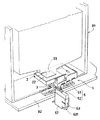
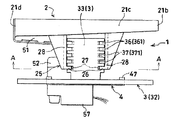
以下、本発明の実施例を、図面を参照して説明する。図1は、本発明に係る遊技機用アウトタンク装置(以下、アウトタンク装置と略称することがある)を遊技機設置島に設置した状態を示す斜視図である。また、図2は本発明に係る遊技機用アウトタンク装置の斜視図、図3は同正面図、図4は同背面図、図5は同底面図、図6は図4のA−A線断面図、図7はベース部の斜視図、図8はベース部に支持部を組み付けた状態の正面図、図9はベース部に支持部を組み付けた状態の底面図、図10は図8のB−B線断面図、図11はタンク部を下降させ且つ前進させた位置に配置した側面図、図12はタンク部を上昇させ且つ後退させた位置に配置した側面図である。なお、本実施例では、遊技機の例としてパチンコ機91を例に説明を行なうが、パチンコ玉を排出する遊技機であれば、パチンコ機91に限られるものではない。
Embodiments of the present invention will be described below with reference to the drawings. FIG. 1 is a perspective view showing a state in which an out tank device for a gaming machine according to the present invention (hereinafter sometimes abbreviated as an out tank device) is installed on a gaming machine installation island. 2 is a perspective view of an out tank apparatus for gaming machines according to the present invention, FIG. 3 is a front view thereof, FIG. 4 is a rear view thereof, FIG. 5 is a bottom view thereof, and FIG. 6 is a line AA in FIG. FIG. 7 is a perspective view of the base portion, FIG. 8 is a front view of the base portion with the support portion assembled, FIG. 9 is a bottom view of the base portion with the support portion assembled, and FIG. FIG. 11 is a cross-sectional view taken along the line BB, FIG. 11 is a side view arranged at a position where the tank portion is lowered and advanced, and FIG. 12 is a side view arranged at a position where the tank portion is raised and retracted. In the present embodiment, a
本発明に係る遊技機用アウトタンク装置1は、排出玉を受け入れるタンク部2と、前記タンク部2を支持する支持部3と、遊技機設置島に固着されるベース部4と、を有している。
The gaming machine out
図1に示すように、遊技機設置島の設置部92には、パチンコ機91が、遊技機設置島の長手方向に列設される。パチンコ機91の裏側には、玉排出口93が設けられ、遊技機用アウトタンク装置1は、タンク部2が玉排出口93に臨むように設置部92に設置される。
As shown in FIG. 1,
次に、パチンコ玉(図示せず)の動きを説明する。パチンコ機91の発射装置(図示せず)が操作されると、パチンコ玉がパチンコ機の遊技領域(図示せず)に打ち込まれる。遊技領域には入賞口(図示せず)とアウト口(図示せず)とが設けられており、パチンコ玉が入賞口に入るとパチンコ機91から景品玉が払い出される。入賞口に入ったセーフ玉と、どの入賞口にも入らずにアウト口に入ったアウト玉は、パチンコ機91の玉排出口93から排出玉として下方へ排出される。
Next, the movement of a pachinko ball (not shown) will be described. When a launching device (not shown) of the
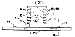
そして、排出玉は、タンク部2によって受け入れられ、タンク部2の底部22を転動し、後述する傾斜通路5を通り、計数機取付部57に取り付けられた計数機63により計数された後、玉出口631から回収樋(図示せず)に送出される。玉出口631と回収樋の距離が離れている場合には、排出玉の落下速度を減速するために、蛇腹状の管(図示せず)を玉出口に631に連通するように取り付け、蛇腹状の管を経由して回収樋(図示せず)に送出される。なお、傾斜通路5は、タンク部側傾斜通路51と計数機側傾斜通路52から構成されている。回収樋により回収された排出玉は、遊技機設置島の略中央に配設された研磨揚送装置(図示せず)により研磨及び揚送され、パチンコ機91に補給される。なお、玉貸機(図示せず)が設置された遊技機設置島では、玉貸機にも補給される。
The discharged balls are received by the
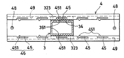
図2及び図3に示すように、タンク部2は、パチンコ機91から排出される排出玉を受け入れるための浅い皿状であって、例えば四方を起立壁21(21a,21b,21c,21d)によって囲まれた略矩形に形成される。
As shown in FIGS. 2 and 3, the
また、タンク部2の底部22には傾斜を設けて、受け入れた玉を所定の方向に集めて流出させるようにする。即ち、本実施例では、底部22を、長手方向に下り傾斜する第1傾斜底部221と、この第1傾斜底部221の下端側に段差部223を介して連通する短手方向に下り傾斜する第2傾斜底部222と、から形成している。そして、起立壁21cと第1傾斜底部221との角部、起立壁21dと第2傾斜底部222との角部には、それぞれ、ゴミを除去するためにタンク部切欠孔224を設けている。
In addition, the
第1傾斜底部221と第2傾斜底部222のそれぞれには、ゴムなどの弾性体からなる板状の部材(図示せず)が敷設される。それぞれの板状の部材は、第1傾斜底部221と第2傾斜底部と略同じ形状であり、板状の部材には凸部(図示せず)が設けられ、第1傾斜底部221と第2傾斜底部222にそれぞれ設けられた凹部(図示せず)に嵌合させて取り付けられる。また、板状の部材は、タンク部切欠孔224の底部22側の形状と略同じ形状に切り欠けていて、切り欠けた部分が、タンク部切欠孔224と連通するようになっている。
A plate-like member (not shown) made of an elastic body such as rubber is laid on each of the first
そして、第2傾斜底部222の流下端側が臨む側面(起立壁21a)に、受け入れた排出玉を傾斜通路5へ送出するための切欠部24を開設している。切欠部24には、前記タンク部2が受け入れた排出玉を、計数機63に送出するための送出口58を有する傾斜通路5を連通させる。
And the
傾斜通路5は、タンク部側傾斜通路51と計数機側傾斜通路52とから構成され、計数機側傾斜通路52は、タンク部側傾斜通路51に対して、本実施例では、回動可能に設けている。
The
タンク部側傾斜通路51は、タンク部側傾斜通路構成部材により形成され、このタンク部側傾斜通路構成部材は、図示していないが、例えばタンク部2の後面側の起立壁21aに取り付ける取付板と、この取付板に略玉1個分の間隔を開けて組み付ける組付板と、から形成されている。取付板には、前記タンク部2の起立壁21aと当接する当接部と、前記タンク部2の切欠部24に対応して開設した開口部53と、を設ける。取付板の下縁には下り傾斜を設け、この傾斜する下縁に沿ってタンク部側傾斜通路51の底板となる通路板を延設する。
The tank portion side inclined
一方、前記のような取付板に組み付ける組付板には、前記した取付板と同様に下縁に下り傾斜を設け、この傾斜する下縁に沿って前記取付板の通路板と突き合わさってタンク部側傾斜通路51の底部を形成する通路片を延設する。
On the other hand, the assembling plate to be assembled to the mounting plate as described above is provided with a downward slope at the lower edge in the same manner as the above-described mounting plate, and is abutted against the passage plate of the mounting plate along the inclined lower edge. A passage piece that forms the bottom of the part-side
前記のような取付板と組付板とは、両者の適宜位置に設けた組付部においてネジ止めして一体化する。また、前記取付板と通路板との角部、及び前記組付板と通路片との角部には、適宜に切欠孔54を開設して、ゴミの除去に利用するとよい。
The mounting plate and the assembly plate as described above are integrated by screwing at an assembly portion provided at an appropriate position between them. Moreover, it is good to open the
前記取付板の当接部には取付孔を開口させて、前記タンク部2の後面側起立壁21aに設けた取付爪を係止可能とする。また、前記組付板の側端縁に前向きに延出する取付片を設け、この取付片には取付孔を開口させて、前記タンク部2の側面側の起立壁21dに設けた取付爪を係止可能とする。このように、取付爪と取付孔とで、タンク部側傾斜通路51をタンク部2に着脱自在に設けることができる。
An attachment hole is opened in the abutting portion of the attachment plate so that an attachment claw provided on the rear
そして、前記通路板と通路片とが組み合わされて形成されるタンク部側傾斜通路51の流下端には、タンク部側玉出口55を形成する(図5参照)。このタンク部側玉出口55には、計数機側傾斜通路52の玉入口を臨ませる。例えば、本実施例では、計数機側傾斜通路52を、後述する回動取付部62を介して、前記タンク部側傾斜通路51に回動可能に臨ませている。
And the tank part side ball |
計数機側傾斜通路52は、計数機側傾斜通路構成部材により形成され、この計数機側傾斜通路構成部材は、計数機63を略挟着状態で装着するための計数機取付部57を備えている。この計数機側傾斜通路構成部材は、略対称に2分割された部材であって、組み合わせたときに略角筒状の計数機側傾斜通路52を形成するための、断面略コ字の凹状通路部を備えている。凹状通路部は玉が転動可能な下り傾斜を有し、傾斜上流側には、前記したタンク部側傾斜通路51のタンク部側玉出口55に連通可能な計数機側傾斜通路52の玉入口を備える回動取付部62が設けてある。一方、傾斜下流側には、後述する計数機の玉入口に連通する、送出口58が設けてあり、円弧状の曲面部を経て流下方向が略直角に変更される。
The counter-side
計数機取付部57は、略対称に2分割された部材であって、樹脂などの弾性体から構成され、例えば、略矩形に形成された一対の面板部と、両面板部の間に形成される開放状態の開放側面部と、略中程まで閉塞された閉塞側面部と、切欠開口部を備えると共に一対の支持片を備える底面部と、から構成されている。それぞれの面板部の開放側面部側の側端縁に、もう一方の面板部に向けて延出する係止片を設け、面板部には係止片の上端部と下端部にそれぞれ切欠部を設け、係止片の間隔が容易に広がるようにしている。
The
なお、本実施例では、計数機側傾斜通路52と計数機取付部57を一体で成型しているため、計数機取付部57の上面は、前記した凹状通路部の底部となっているが、計数機取付部57に上面を設けて、別体で成型して、両者の適宜位置に設けた組付部において、ネジなどにより止めて一体化しても良い。
In this embodiment, since the counter-side
上記のような計数機取付部に計数機63を装着するには、係止片の間隔を広げて、計数機63を開放側側面部から閉塞側側面部に向って挿入し、計数機63の奥端面を閉塞側側面部に当接するまで押し込めばよい。この状態では、面板部の縁に設けた係止片が計数機63の側縁に係止すると共に、底面部の支持片が計数機63を下方から支える。
In order to attach the
なお、計数機63の具体的な構造は図示していないが、玉入口及び玉出口631を有する計数通路を通過する玉によってスプロケットが所定角度回動し、例えば10個の玉が通過して前記スプロケットが1回転すると、検出信号として1パルスを発するように構成してある。
Although the specific structure of the
タンク部側傾斜通路51に対して計数機側傾斜通路52を回動可能に取り付ける回動取付部62は、例えば、計数機側傾斜通路構成部材の上面に設けたフランジ部を、タンク部側傾斜通路構成部材の下面に設けた回動溝に係止させることにより構成してある。また、タンク部側傾斜通路構成部材の下面で前記タンク部側玉出口55の周囲に、複数の係止歯部621を略半円の円弧状に配設すると共に、計数機側傾斜通路構成部材の上面に前記係止歯部621に係止可能な弾性係止腕622を設け、前記係止歯部621の何れかに前記弾性係止腕622を係止させることにより、計数機側傾斜通路構成部材を所望の回動位置で停止可能に構成してある。本実施例では、タンク部2の側方に回動取付部62を設けたことにより、タンク部2の下部に回動取付部62を設けた場合に比べて、回動可能な範囲が広くなっている。
For example, the
そこで、例えば図1に示す中央位置から、計数機側傾斜通路構成部材を右方向に回動させれば、送出口58に連通する計数機63の玉出口631が右側に位置する。一方、左方向に回動させれば、送出口58に連通する計数機63の玉出口631が左側に位置する。従って、回収樋の傾斜上流側では、回収樋からの高さを充分に確保できない場合であっても、回収樋の傾斜下流側に計数機63の玉出口631を設定すれば、回収樋と干渉することなくアウトタンク装置1を配置可能となる。そして、計数機63で計数された排出玉は、玉出口631から回収樋へ向けて送出される。なお、玉出口631と回収樋の間に十分なスペースがあれば、蛇腹状の管を経由して回収樋へ送出しても良い。
Therefore, for example, if the counter side inclined passage constituting member is rotated rightward from the center position shown in FIG. 1, the
また、回収樋の下方に下部タンクを設けている場合、回収樋が下部タンクの上部を完全に塞いでしまうと、タンク内部の玉の状態が確認できないため、下部タンクの幅より、回収樋の幅を狭くして、タンク内部の玉の状態を上部から確認できるようにしていることがある。その場合、計数機側傾斜通路構成部材の回動操作により送出口58の位置を前後方向に移動させることにより、排出玉を下部タンクに落下させるか、回収樋に落下させるかを選択することが可能となる。
In addition, when a lower tank is provided below the recovery tank, if the recovery tank completely closes the upper part of the lower tank, the state of the balls inside the tank cannot be confirmed. The width may be narrowed so that the state of the ball inside the tank can be confirmed from above. In that case, it is possible to select whether the discharged balls are dropped into the lower tank or the collection tank by moving the position of the
また、人気がある遊技機のため、入れ替えをする必要がなく、同一の遊技機を数年に渡って使用するような場合、回動操作により送出口58の位置を少しずつ変更することにより、回収樋の略同じ位置に排出玉が当たり続けることにより回収樋が痛むことを避けることが可能となる。
In addition, because it is a popular gaming machine, it is not necessary to replace it, and when using the same gaming machine for several years, by changing the position of the
図7に示すように、ベース部4は、遊技機設置島の設置部92に固着される。ベース部4の両端付近に開設した取付孔48(図5参照)にネジを通し、このネジを遊技機設置島の設置部92に締め付けることにより、当該ベース部4を設置部92に固着している。
As shown in FIG. 7, the
図7及び図10に示すように、ベース部4は、ベース部構成部材から構成される。ベース部構成部材は、板状の部材であるベース底面部41と、長手方向に延びる一対の主起立リブ42と、長手方向に延びる一対の副起立リブ44と、主起立リブ42と副起立リブとの間隔を結ぶ、間隔保持リブ43と後述するガイド爪47とからなる。
As shown in FIG.7 and FIG.10, the
副起立リブ44は、外側の端部が自由端になっており、主起立リブ42との間隔を狭める方向に弾性を有し、この自由端に弾性係止部45を形成している。更に、自由端側の先端、即ち弾性係止部45の先端には、外向きの山形に突出する係止凸部451が設けてある。そして、この係止凸部451を設けた弾性係止部45は、ベース部4におけるベース部係合部46を構成している。
The
ガイド爪47は、後述する支持部3の長手方向の移動をガイドするためのもので、ベース底面部41の四隅に設けている。また、ガイド爪47には、外向きのガイド段部471を設け、このガイド段部471に、後述する支持部3が係止する。なお、ベース底面部41には、適宜に補強リブを設けて、強度を上げるようにするとよい。
The
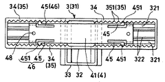
図8に示すように、支持部3は、前記タンク部2を支持するためのものであって、支持部構成部材31からなり、この支持部構成部材31は、図示の実施例によれば、前記したベース部4に対応する土台部32と、この土台部32に立設する柱部33とからなる。
As shown in FIG. 8, the
土台部32は、前記ベース部4に対応するように、設置部92の長手方向に延びる板状の部材である。一方、前記タンク部2を支える柱部33は、土台部32の上に角柱状に形成されている。なお、前記土台部32と柱部33とは、一体的に形成されている。また、本実施例では、前記柱部33の中心は、土台部32の中心から偏心した位置に設けてある。言い換えると、柱部33の前後方向の幅は土台部32の前後方向の幅よりも長く、柱部33の一端面と土台部32の一端面は揃っているが、柱部33の他方の端面は土台部32の端面から突出している(図11参照)。なお、柱部33の前後方向の幅を、土台部32の前後方向の幅と同じ長さにしても良い。その場合、後述するタンク部係合部25の互いに対向する係合片281のそれぞれに、複数の弾性係止部27を適宜設ければよい。
The
図5及び図9に示すように、支持部3には、前記ベース部係合部46が係合するベース部側被係合部34を設ける。即ち、前記ベース部4に設けたベース部係合部46である弾性係止部45が係止するように、ベース部側被係合部34として被係止部35を設ける。この被係止部35は、複数の係止凹部351を土台部32の側縁壁の内側に形成してなる。そこで、前記した弾性係止部45の係止凸部451が、何れかの係止凹部351に嵌合し、左右の位置が調整でき、これらが左右方向位置調整機構を構成している。
As shown in FIGS. 5 and 9, the
また、図9及び図10に示すように、土台部32には、前記したガイド部のガイド爪47が挿通されるガイド溝321を設けると共に、前記ベース部4の主起立リブ42に対応するガイドリブ322を裏面側に設けている。そこで、主起立リブ42にガイドリブ322が摺接すると共に、前記ガイド溝321に通したガイド爪47のガイド段部471が、ガイド溝321の縁部に係止して、ベース部4の長さ方向、即ち左右方向にガイドされる。なお、このとき弾性係止部45の係止凸部451が、被係止部35の係止凹部351の山を乗り越える。
As shown in FIGS. 9 and 10, the
図4、図8及び図12に示すように、支持部3には、後述するタンク部係合部25に対応するタンク部側被係合部36を設ける。このタンク部側被係合部36は、支持部3を形成する柱部33の側面に、複数の案内溝361を上下方向に略平行に設けることにより構成してある。また、各案内溝361には、後述するタンク部2のスライド部26に設ける弾性係止部27が係止する被係止部37を設ける。この被係止部37は、例えば案内溝361の奥部に谷型の凹部371を、当該案内溝361に沿って連続的に設けることにより構成する。
As shown in FIGS. 4, 8, and 12, the
図4及び図6に示すように、前記したタンク部側被係合部36に対応するタンク部係合部25を、タンク部2の下方に設ける。このタンク部係合部25は、例えばタンク部2の底面に支持壁28を設け、この支持壁28の下縁に互いに対向する係合片281を設けて構成する。そして、この係合片281が前記した案内溝361にスライド可能に嵌合し、タンク部2に設けるスライド部26を構成する。このスライド部26、即ち係合片281には、更に前記案内溝361に設けた被係止部37に係止する弾性係止部27を設ける。
As shown in FIGS. 4 and 6, a tank
弾性係止部27は、例えば、前記係合片281に弾性空間部を切り欠くことによって構成する。また、この弾性係止部27の先端には、前記した案内溝361の被係止部37に係合する係止凸部271を設ける。
The
そこで、支持部3に設けた複数の案内溝361から、一つの案内溝361を選択し、この選択した案内溝361に、タンク部2に設けたスライド部26を係合させると、タンク部2を支持部3により支持することができる。そして、スライド部26を係合させる案内溝361を変更すると、タンク部2の上下方向の位置を調整できる。即ち、タンク部2のタンク部係合部25及び支持部3のタンク部側被係合部36が、上下方向位置調整機構を構成する。
Therefore, when one
例えば、図11に示すように、支持部3に設けた一番下の案内溝361に、タンク部2のスライド部26を係合させれば、タンク部2の高さ位置を下げることができる。一方、図12に示すように、支持部3に設けた一番上の案内溝361に、タンク部2のスライド部26を係合させれば、タンク部2の高さ位置を上げることができる。
For example, as shown in FIG. 11, if the
このとき、前記スライド部26の弾性係止部27に設けた係止凸部271が、支持部3に設けた案内溝361の被係止部37の凹部371に係止する。従って、係止凸部271が係止する凹部371を変更することにより、タンク部2の前後方向の位置調整が可能となる。そして、タンク部2のタンク部係合部25及び支持部3のタンク部側被係合部36、具体的には、タンク部2のタンク部係合部25のスライド部26に設けた弾性係止部27の係止凸部271、及び支持部3の案内溝361に設けた被係止部37の凹部371が、前後方向位置調整機構を構成する。
At this time, the locking
そこで、例えば、図11に示すように、タンク部2の係止凸部271を、支持部3の比較的前側(図において右側)の凹部371に係止させれば、タンク部2をパチンコ機91に比較的近づけて配置することができる。一方、図12に示すように、タンク部2の係止凸部271を、支持部3の後側(図において左側)の凹部371に係止させれば、タンク部2をパチンコ機91から比較的遠ざけて配置することができる。
Therefore, for example, as shown in FIG. 11, if the locking
前記したようなアウトタンク装置1によれば、タンク部2の位置を、左右方向、上下方向、及び前後方向に、容易に調整することができ、遊技機設置島の設置部92に配設したパチンコ機91の玉排出口93の位置が異なっていても、玉排出口93から排出される排出玉を正しく受け入れる位置にタンク部2を配置することができる。従って、パチンコ機91から排出される排出玉の計数漏れが発生しにくくなり、遊技場の経営をより正確な数値に基づいて行なうことができる。また、パチンコ機91の設置作業や交換作業のときには、タンク部2を容易に外すことができ、作業に支障をきたしたり、タンク部2を破損する恐れもない。
According to the
図13は、本発明に係るアウトタンク装置1の他の実施例を示す、要部の概略正面図である。即ち、この実施例では、支持部3を土台部32と柱部33とから構成し、タンク部側被係合部36を柱部33の内側に形成し、タンク部係合部25をタンク部2の下方に前記柱部33の内部に嵌合するように形成している。具体的には、中空状の柱部33の内壁に、複数の案内溝361を上下方向に略平行に設け、各案内溝361には被係止部37として凹部371を設けている。
FIG. 13: is a schematic front view of the principal part which shows the other Example of the
一方、タンク部係合部25は、タンク部2の下方に突設した支持柱29に、前記案内溝361に嵌合するスライド部26を設け、該スライド部26には更に係止凸部271を有する弾性係止部27を設けて構成する。
On the other hand, the tank
この実施例によっても、スライド部26を嵌合する案内溝361を選択することにより、タンク部2の上下方向の位置を調整することができる。また、案内溝内に設けた凹部371に、スライド部26の係止凸部271を係止させることにより、タンク部2の前後方向の位置を調整することができる。
Also in this embodiment, the vertical position of the
図14は、アウトタンク装置1の他の実施例を示す概略正面図である。この実施例では、支持部3の内側にタンク部2が位置するように構成してある。即ち、柱部33の上方に、タンク部2を内包可能な装着部38を設け、この装着部38の内壁に複数の案内溝361を設けている。また、この案内溝361に嵌合するスライド部26をタンク部2の側面に設けている。なお、図示していないが、この実施例においても、タンク部側被係合部36としての前記案内溝361の内部に被係止部として凹部を設け、タンク部係合部25としてのスライド部26には、弾性係止部としての係止凸部を設けている。
FIG. 14 is a schematic front view showing another embodiment of the
この実施例によっても、スライド部26を嵌合する案内溝361を選択することにより、タンク部2の上下方向の位置を調整することができる。また、案内溝361内に設けた凹部に、スライド部26の係止凸部を係止させることにより、タンク部2の前後方向の位置を調整することができる。なお、この実施例において、左右方向の位置調整は、前記した実施例と同様に、ベース部4と支持部3との関係によって調整する。
Also in this embodiment, the vertical position of the
図15は、アウトタンク装置1の他の実施例を示す概略正面図である。この実施例では、支持部3の内側にタンク部2が位置するように構成してある。即ち、柱部33の上方に、タンク部2を内包可能な装着部38を設け、この装着部38の内壁にタンク部側被係合部36としてスライド部362を設けている。一方、タンク部2の側面に複数の案内溝251を設けている。この実施例においても、図示していないが、タンク部側被係合部36としての前記スライド部362には、弾性係止部としての係止凸部を設け、タンク部係合部25としての案内溝251の内部には被係止部としての凹部が設けてある。
FIG. 15 is a schematic front view showing another embodiment of the
この実施例によっても、スライド部362を嵌合する案内溝251を選択することにより、タンク部2の上下方向の位置を調整することができる。また、案内溝251内に設けた凹部に、スライド部362の係止凸部を係止させることにより、タンク部2の前後方向の位置を調整することができる。なお、この実施例において、左右方向の位置調整は、前記した実施例と同様に、ベース部4と支持部3との関係によって調整する。
Also in this embodiment, the vertical position of the
図16は、アウトタンク装置1の更に他の実施例を示す要部の説明図である。この実施例においては、計数機側傾斜通路52の取付方向を、左右方向に変更可能に構成している。即ち、この実施例では、タンク部側傾斜通路51の流下端に、挿入取付部64を設け、この挿入取付部64に計数機側傾斜通路52の取付片56を挿入することにより、計数機側傾斜通路52の取付方向を変更可能としている。
FIG. 16 is an explanatory view of a main part showing still another embodiment of the
具体的には、タンク部側傾斜通路51に設ける挿入取付部64は、対向する一対の挿入溝641からなり、図16において手前側の面及び下面が開放している。一方、計数機側傾斜通路52に設ける取付片56は、当該計数機側傾斜通路52の流下上流部分に、鍔状に突設した部材であって、図示していないが、中央に計数機側傾斜通路52の玉入口を備えている。
Specifically, the
そこで、例えば図16に示すように、計数機63の玉出口631を右側にした状態で、タンク部側傾斜通路51に設けた挿入取付部64の挿入溝641に、計数機側傾斜通路52に設けた取付片56を挿入すれば、取付片56が挿入溝641の縁に係止するため、計数機側傾斜通路52とタンク部側傾斜通路51とが連通し、玉出口631を右側に備える傾斜通路5を形成することができる。一方、図16の左半部分に示しように、計数機63の玉出口631を左側にした状態で、計数機側傾斜通路52の取付片56を挿入溝641に挿入すれば、玉出口631を左側に備える傾斜通路5を形成することができる。なお、挿入取付部64に、挿入された取付片56を係止する弾性係止部を設けても良い。
Therefore, for example, as shown in FIG. 16, with the
この実施例によれば、計数機63の玉出口631を、左右何れにも位置させることができ、図示していない回収樋との間隔が充分にない場合であっても、アウトタンク装置1を配設することができる。なお、前記した実施例と同じ機能を有する部位には、同じ符号を付して説明を省略する。
According to this embodiment, the
図17は、ベース部4と支持部3の他の実施例を示す正面図である。図18は、図17のC−C線断面図である。図19はベース部に支持部を組み付ける途中を示す図である。
FIG. 17 is a front view showing another embodiment of the
図17から図19に示すように、本実施例では、支持部3は、柱部33と土台部32から構成される。土台部32は、ベース部側被係合部34とガイド部323から構成される。ベース部側被係合部34は、複数の係止凹部351を有する。
As shown in FIGS. 17 to 19, in the present embodiment, the
ベース部4は、ガイド溝49を有し、ガイド溝49にガイド部323が嵌合することにより長手方向の移動をガイドしている。ベース部4の取付口48にネジを通し、このネジを設置部92に締め付けることにより、当該ベース部4を設置部92に固着している。当該ベース部4は、ベース部係合部46を有し、ベース部係合部46は、弾性係止部45を有し、弾性係止部45は係止凸部451を有する。ベース部4の係止凸部451は、支持部3の係止凹部351に係止する。従って、ベース部4の係止凸部451が係止する、支持部3の係止凹部351を変更することにより、タンク部2の左右方向の位置調整が可能となる。そして、ベース部4のベース部係合部46及び支持部3のベース部側被係合部34が左右方向位置調整機構を構成する。
The
本実施例では、ベース部4に弾性係止部45を複数設け、土台部32の左右方向の幅を、ベース部4の左右方向の幅より狭くしたことにより、タンク部2の左右方向の移動可能な幅を広くすることが可能となる。
In this embodiment, the
以上本発明を図面の実施例について説明したが、本発明は前記した各実施例に限定されるものではなく、特許請求の範囲に記載した構成を変更しない限り適宜に実施できる。例えば、タンク部係合部にスライド部を設け、このスライド部に弾性係止部を設けると共に、タンク部側被係合部に案内溝を設け、この案内溝に被係止部として凹部を設けているが、タンク部係合部に案内溝を設けると共に、タンク部側被係合部にスライド部を設けてもよい。また、スライド部に被係止部を設けると共に、案内溝に弾性係止部を設けるようにしてもよい。 Although the present invention has been described with reference to the embodiments shown in the drawings, the present invention is not limited to the embodiments described above, and can be appropriately implemented without changing the configuration described in the claims. For example, a slide part is provided in the tank part engaging part, an elastic locking part is provided in the sliding part, a guide groove is provided in the tank part side engaged part, and a concave part is provided in the guide groove as a locked part. However, a guide groove may be provided in the tank portion engaging portion, and a slide portion may be provided in the tank portion side engaged portion. Moreover, while providing a to-be-latched part in a slide part, you may make it provide an elastic latching | locking part in a guide groove.
1 遊技機用アウトタンク装置
2 タンク部
3 支持部
4 ベース部
5 傾斜通路
24 切欠部
25 タンク部係合部
26 スライド部
27 弾性係止部
31 支持部構成部材
32 土台部
33 柱部
34 ベース部側被係合部
35 被係止部
36 タンク部側被係合部
37 被係止部
41 ベース底面部
45 弾性係止部
46 ベース部係合部
51 タンク部側傾斜通路
52 計数機側傾斜通路
57 計数機取付部
58 送出口
62 回動取付部
63 計数機
91 パチンコ機
92 設置部
93 玉排出口
251 案内溝
271 係止凸部
281 係合片
351 係止凹部
361 案内溝
362 スライド部
371 凹部
451 係止凸部
631 玉出口
DESCRIPTION OF
Claims (5)
前記遊技機用アウトタンク装置は、前記排出玉を受け入れるタンク部と、前記タンク部を支持する支持部と、前記遊技機設置島に固定されるベース部と、を有し、
前記タンク部または前記支持部のどちらか一方に前後方向に延設される案内溝を上下方向に複数設けると共に他方に何れかの前記案内溝にスライド可能に係合するスライド部を設け、
各案内溝の延設端部を前後方向に開放して前記スライド部が当該延設端部を介して何れかの案内溝内に進入または当該案内溝から外れるよう構成することで、前記スライド部が係合する前記案内溝を変更可能にして前記タンク部の上下方向の位置を調整可能な上下方向位置調整機構を形成し、
前記タンク部または前記支持部のどちらか一方に第1係止凸部を有する第1弾性係止部を設けると共に他方に前記スライド部と前記案内溝とを係合することで前記第1係止凸部と係止する第1被係止部を設け、
前記第1被係止部を前記案内溝の延設方向に沿って設けた複数の凹部により構成することで、前記スライド部が前記案内溝を前後方向にスライドすることにより前記第1係止凸部が係止する前記凹部を変更可能にして前記タンク部の前後方向の位置を調整可能な前後方向位置調整機構を形成したことを特徴とする遊技機用アウトタンク装置。 In an out tank device for gaming machines that accepts discharged balls discharged from gaming machines installed on the gaming machine installation island and sends out the discharged balls received,
The gaming machine out tank apparatus has a tank portion that receives the discharged balls, a support portion that supports the tank portion, and a base portion that is fixed to the gaming machine installation island,
A plurality of guide grooves extending in the front-rear direction are provided in either the tank part or the support part in the up- and- down direction, and a slide part that is slidably engaged with any of the guide grooves is provided in the other,
The slide portion is configured such that the extended end portion of each guide groove is opened in the front-rear direction so that the slide portion enters or exits any of the guide grooves via the extended end portion. Forming a vertical position adjustment mechanism capable of changing the guide groove with which the tank portion engages and adjusting the vertical position of the tank portion;
Either the tank portion or the support portion is provided with a first elastic locking portion having a first locking convex portion, and the other locking portion is engaged with the slide portion and the guide groove, thereby the first locking. A first locked portion that locks with the convex portion is provided,
By configuring the first locked portion by a plurality of concave portions provided along the extending direction of the guide groove, the slide portion slides the guide groove in the front-rear direction so that the first locking protrusion An out-tank device for a gaming machine, characterized in that a front-rear direction position adjustment mechanism capable of adjusting the front-rear direction position of the tank part by changing the concave part to which the part is locked is formed.
前記ベース部係合部または前記ベース部側被係合部のどちらか一方に第2弾性係止部を設けると共に他方に前記第2弾性係止部に係止する第2被係止部を設け、
前記第2弾性係止部には第2係止凸部を形成すると共に、前記第2被係止部には複数の係止凹部を左右方向に形成することで、前記第2係止凸部が係止する前記係止凹部を変更可能にして前記タンク部の左右方向の位置を調整可能な左右方向位置調整機構を設けたことを特徴とする請求項1記載の遊技機用アウトタンク装置。 A base portion engaging portion is provided in the base portion, and a base portion side engaged portion with which the base portion engaging portion is engaged is provided in the support portion;
A second elastic locking portion is provided on either the base portion engaging portion or the base portion side engaged portion, and a second locked portion is provided on the other side to be locked to the second elastic locking portion. ,
A second locking projection is formed on the second elastic locking portion, and a plurality of locking recesses are formed on the second locked portion in the left-right direction. The out-tank device for a gaming machine according to claim 1, further comprising a left-right position adjustment mechanism capable of adjusting the position of the tank portion in the left-right direction by changing the locking recess to be locked.
前記傾斜通路には、前記送出口に連通するように計数機を取り付け可能な計数機取付部を設け、
前記傾斜通路は、タンク部側傾斜通路と、計数機側傾斜通路とから構成され、
前記計数機側傾斜通路を前記タンク部側傾斜通路に取り付ける方向を、左右方向に変更可能にしたことを特徴とする請求項1又は2記載の遊技機用アウトタンク装置。 In the tank part, an inclined passage having a delivery port for delivering the received discharged balls is provided,
The inclined passage is provided with a counter mounting portion capable of mounting a counter so as to communicate with the delivery port,
The inclined passage is composed of a tank portion side inclined passage and a counter side inclined passage,
The out tank device for a gaming machine according to claim 1 or 2, wherein a direction in which the counter side inclined passage is attached to the tank portion side inclined passage can be changed in a left-right direction.
前記傾斜通路には、前記送出口に連通するように計数機を取り付け可能な計数機取付部を設け、
前記傾斜通路は、タンク部側傾斜通路と、計数機側傾斜通路とから構成され、
前記計数機側傾斜通路を前記タンク部側傾斜通路に対して回動可能に取り付けたことを特徴とする請求項1又は2記載の遊技機用アウトタンク装置。 In the tank part, an inclined passage having a delivery port for delivering the received discharged balls is provided,
The inclined passage is provided with a counter mounting portion capable of mounting a counter so as to communicate with the delivery port,
The inclined passage is composed of a tank portion side inclined passage and a counter side inclined passage,
The out tank device for a gaming machine according to claim 1 or 2, wherein the counter side inclined passage is rotatably attached to the tank portion side inclined passage.
前記タンク部の側面には、前記タンク部側傾斜通路に連通する切欠部を設けたことを特徴とする請求項3又は4記載の遊技機用アウトタンク装置。 The tank portion side inclined passage is provided on a side surface of the tank portion,
The out tank apparatus for a gaming machine according to claim 3 or 4, wherein a cutout portion communicating with the tank portion side inclined passage is provided on a side surface of the tank portion.
Priority Applications (1)
| Application Number | Priority Date | Filing Date | Title |
|---|---|---|---|
| JP2005055968A JP4649232B2 (en) | 2005-03-01 | 2005-03-01 | Out tank equipment for gaming machines |
Applications Claiming Priority (1)
| Application Number | Priority Date | Filing Date | Title |
|---|---|---|---|
| JP2005055968A JP4649232B2 (en) | 2005-03-01 | 2005-03-01 | Out tank equipment for gaming machines |
Related Child Applications (1)
| Application Number | Title | Priority Date | Filing Date |
|---|---|---|---|
| JP2010185152A Division JP2010253326A (en) | 2010-08-20 | 2010-08-20 | Out tank device for game machine |
Publications (3)
| Publication Number | Publication Date |
|---|---|
| JP2006238999A JP2006238999A (en) | 2006-09-14 |
| JP2006238999A5 JP2006238999A5 (en) | 2009-07-02 |
| JP4649232B2 true JP4649232B2 (en) | 2011-03-09 |
Family
ID=37045996
Family Applications (1)
| Application Number | Title | Priority Date | Filing Date |
|---|---|---|---|
| JP2005055968A Active JP4649232B2 (en) | 2005-03-01 | 2005-03-01 | Out tank equipment for gaming machines |
Country Status (1)
| Country | Link |
|---|---|
| JP (1) | JP4649232B2 (en) |
Families Citing this family (8)
| Publication number | Priority date | Publication date | Assignee | Title |
|---|---|---|---|---|
| JP5194422B2 (en) * | 2006-10-17 | 2013-05-08 | 株式会社三洋物産 | Game machine |
| JP5069972B2 (en) * | 2007-08-20 | 2012-11-07 | アイ電子株式会社 | Outlet counter for pachinko machine |
| JP2009183395A (en) * | 2008-02-05 | 2009-08-20 | Daito Hanbai Kk | Game ball recovery device |
| JP4783800B2 (en) * | 2008-02-21 | 2011-09-28 | 大都販売株式会社 | Game ball collection device |
| JP5160509B2 (en) * | 2009-07-21 | 2013-03-13 | 株式会社大都製作所 | Ball supply device for gaming machines |
| JP5471298B2 (en) * | 2009-10-26 | 2014-04-16 | 株式会社竹屋 | Out ball container |
| JP6060354B2 (en) * | 2012-08-23 | 2017-01-18 | 株式会社ソフイア | Game machine |
| CN112960291B (en) * | 2021-02-26 | 2022-08-19 | 中国水利水电第九工程局有限公司 | Discharge hopper for machine-made sand shell breaking, core keeping and desliming process |
Family Cites Families (5)
| Publication number | Priority date | Publication date | Assignee | Title |
|---|---|---|---|---|
| JPH0515654A (en) * | 1991-07-10 | 1993-01-26 | Ace Denken:Kk | Magnetic card for game machine |
| JP2758364B2 (en) * | 1994-09-06 | 1998-05-28 | 秀工電子株式会社 | Counter mounting device |
| JP3843466B2 (en) * | 1995-04-06 | 2006-11-08 | 株式会社竹屋 | Pachinko ball collection device |
| JP4270592B2 (en) * | 1997-04-07 | 2009-06-03 | 株式会社三和商会 | Out ball tank device of pachinko machine |
| JPH1157192A (en) * | 1997-08-26 | 1999-03-02 | Daito Seisakusho:Kk | Pachinko ball collector |
-
2005
- 2005-03-01 JP JP2005055968A patent/JP4649232B2/en active Active
Also Published As
| Publication number | Publication date |
|---|---|
| JP2006238999A (en) | 2006-09-14 |
Similar Documents
| Publication | Publication Date | Title |
|---|---|---|
| JP4649232B2 (en) | Out tank equipment for gaming machines | |
| JP2002210173A (en) | Game machine | |
| JP3847455B2 (en) | Game media lending machine and its nozzle chute | |
| JP5610447B2 (en) | Out tank equipment for gaming machines | |
| JP2010253326A (en) | Out tank device for game machine | |
| JP2004275744A (en) | Pachinko game machine | |
| JP4483326B2 (en) | Ball hopper | |
| JP5179735B2 (en) | Game machine | |
| JP4115346B2 (en) | Game machine | |
| JP2003181113A (en) | Pachinko ball collector | |
| JP2007007059A (en) | Ball feeder of pinball game machine | |
| JP2017064523A5 (en) | ||
| JP4674876B1 (en) | Medal payout device and medal game machine using the same | |
| JPH1157192A (en) | Pachinko ball collector | |
| JP4551707B2 (en) | Game machine | |
| JP2019115854A (en) | Game machine | |
| JP2019115853A (en) | Game machine | |
| JP5794663B2 (en) | Ball dispensing device in pachinko machines | |
| JP2001231999A5 (en) | ||
| JP2018126623A (en) | Game machine | |
| JP2006043054A (en) | Aligning path, storage tank and ball hopper | |
| JP4573999B2 (en) | Ball tank equipment | |
| JP3480921B2 (en) | Pachinko machine | |
| JP2017124278A5 (en) | ||
| JP5342032B2 (en) | Game machine |
Legal Events
| Date | Code | Title | Description |
|---|---|---|---|
| A621 | Written request for application examination |
Free format text: JAPANESE INTERMEDIATE CODE: A621 Effective date: 20071001 |
|
| A521 | Request for written amendment filed |
Free format text: JAPANESE INTERMEDIATE CODE: A523 Effective date: 20090519 |
|
| A131 | Notification of reasons for refusal |
Free format text: JAPANESE INTERMEDIATE CODE: A131 Effective date: 20100622 |
|
| A977 | Report on retrieval |
Free format text: JAPANESE INTERMEDIATE CODE: A971007 Effective date: 20100624 |
|
| A521 | Request for written amendment filed |
Free format text: JAPANESE INTERMEDIATE CODE: A523 Effective date: 20100820 |
|
| TRDD | Decision of grant or rejection written | ||
| A01 | Written decision to grant a patent or to grant a registration (utility model) |
Free format text: JAPANESE INTERMEDIATE CODE: A01 Effective date: 20101124 |
|
| A01 | Written decision to grant a patent or to grant a registration (utility model) |
Free format text: JAPANESE INTERMEDIATE CODE: A01 |
|
| A61 | First payment of annual fees (during grant procedure) |
Free format text: JAPANESE INTERMEDIATE CODE: A61 Effective date: 20101213 |
|
| FPAY | Renewal fee payment (event date is renewal date of database) |
Free format text: PAYMENT UNTIL: 20131217 Year of fee payment: 3 |
|
| R150 | Certificate of patent or registration of utility model |
Ref document number: 4649232 Country of ref document: JP Free format text: JAPANESE INTERMEDIATE CODE: R150 Free format text: JAPANESE INTERMEDIATE CODE: R150 |
|
| R250 | Receipt of annual fees |
Free format text: JAPANESE INTERMEDIATE CODE: R250 |
|
| R250 | Receipt of annual fees |
Free format text: JAPANESE INTERMEDIATE CODE: R250 |
|
| R250 | Receipt of annual fees |
Free format text: JAPANESE INTERMEDIATE CODE: R250 |
|
| R250 | Receipt of annual fees |
Free format text: JAPANESE INTERMEDIATE CODE: R250 |
|
| R250 | Receipt of annual fees |
Free format text: JAPANESE INTERMEDIATE CODE: R250 |
|
| R250 | Receipt of annual fees |
Free format text: JAPANESE INTERMEDIATE CODE: R250 |
|
| R250 | Receipt of annual fees |
Free format text: JAPANESE INTERMEDIATE CODE: R250 |
|
| R250 | Receipt of annual fees |
Free format text: JAPANESE INTERMEDIATE CODE: R250 |