JP4986552B2 - Measuring method of inclination angle of conical part of threaded drum - Google Patents
Measuring method of inclination angle of conical part of threaded drum Download PDFInfo
- Publication number
- JP4986552B2 JP4986552B2 JP2006242272A JP2006242272A JP4986552B2 JP 4986552 B2 JP4986552 B2 JP 4986552B2 JP 2006242272 A JP2006242272 A JP 2006242272A JP 2006242272 A JP2006242272 A JP 2006242272A JP 4986552 B2 JP4986552 B2 JP 4986552B2
- Authority
- JP
- Japan
- Prior art keywords
- cone
- drum
- screw
- shaped portion
- measurement
- Prior art date
- Legal status (The legal status is an assumption and is not a legal conclusion. Google has not performed a legal analysis and makes no representation as to the accuracy of the status listed.)
- Expired - Fee Related
Links
- 238000000034 method Methods 0.000 title claims description 23
- 238000005259 measurement Methods 0.000 claims description 48
- 238000000691 measurement method Methods 0.000 claims description 5
- 238000010586 diagram Methods 0.000 description 4
- 238000012545 processing Methods 0.000 description 4
- NCGICGYLBXGBGN-UHFFFAOYSA-N 3-morpholin-4-yl-1-oxa-3-azonia-2-azanidacyclopent-3-en-5-imine;hydrochloride Chemical compound Cl.[N-]1OC(=N)C=[N+]1N1CCOCC1 NCGICGYLBXGBGN-UHFFFAOYSA-N 0.000 description 2
- 238000007796 conventional method Methods 0.000 description 2
- 238000013461 design Methods 0.000 description 2
- 239000000523 sample Substances 0.000 description 2
- 238000012937 correction Methods 0.000 description 1
Images
Landscapes
- A Measuring Device Byusing Mechanical Method (AREA)
Description
この発明は、テーパころ軸受のテーパころ等の外径面を、センタレス研削加工や超仕上げ加工する際等に用いられるねじ状ドラムの円錐形状部の傾斜角度測定方法に関するものである。 The present invention relates to a method for measuring an inclination angle of a conical portion of a screw-like drum used when an outer diameter surface such as a tapered roller of a tapered roller bearing is subjected to centerless grinding or superfinishing.
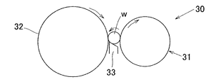
図4に示すようなテーパころ軸受用のテーパころ1は、図5および図6に示すセンタレス研削装置30や、図7および図8に示すような超仕上げ加工装置40によって研削加工や仕上げ加工がなされる。センタレス研削装置30は、ねじ状回転軸ドラム31と回転砥石32との間に、テーパころワークwをブレード33によって支持した状態で配する。この状態で、ねじ状回転軸ドラム31および砥石32を図5および図6のように回転させ、ドラム31の表面に形成された円錐形状部31aの回転作用により、図6の白抜矢示a方向にワークwを推進させながら、回転する砥石32によって研削加工する。ドラム31は、ドラム軸軸受サポート部31bによって支持されている。
The
超仕上げ加工装置40では、2本の平行なねじ状回転軸ドラム41,42の間にテーパころ用ワークwを配し、ワークwに固定の砥石43を当接させる。ドラム41,42を図7および図8のように回転させ、ドラム41,42の表面に形成された円錐形状部41a,42aの回転作用により、図8の白抜矢示b方向にワークwを推進させながら砥石43によって仕上げ加工する。ドラム41,42はドラム軸軸受サポート部41b,42bによって支持されている。
In the
これらの研削加工および仕上げ加工装置30,40においては、ワークwを支持するねじ状回転軸ドラム31,41,42が用いられる。これらドラム31,41,42の円錐形状部31a,41a,42aは、加工時にワークwの外径面に接しており、その角度はワークwの外径面の頂角や加工条件によって決まる。そのため、円錐形状部31a,41a,42aの角度を正確に作る必要がある。このようなドラム31,41,42は、図9および図10に示すねじ研削盤50によって研削加工される。
In these grinding and
このねじ研削盤50は、テーブル51上のドラム軸軸受サポート部52にドラム31(41,42)用ワークWを支持させ、このワークWの表面に研削作用面が所定角度に形成された回転砥石53を当接させる。ワークWおよび回転砥石53を、図9,図10のように回転させ、かつワークWを図9の白抜矢示c方向にトラバースさせることによって、ワークWの表面に角度δdの円錐形状部Waを研削加工形成する。
The
上記のように研削加工して得たねじ状回転軸ドラム用ワークWの円錐形状部Waの角度δdは、図11に示すように求める。すなわち、ねじ研削盤50上で、砥石53側よりゲージ60を円錐形状部Waに当て、ワークWは回転させないで、軸方向(白抜矢示d方向)に移動させ、その移動距離Lmとゲージ振れ量Hmとにより、ドラム円錐形状部の傾斜角度δdが次式(1)により求められる。
δd=tan-1(Hm/Lm) ……(1)
The angle δd of the conical portion Wa of the threaded rotary shaft drum workpiece W obtained by grinding as described above is obtained as shown in FIG. That is, on the
δd = tan −1 (Hm / Lm) (1)
上記のような測定方法においては、ゲージ振れ量および移動距離の両方を正確に測定する必要があり、測定に時間が掛かっていた。また、移動開始時や終了時にゲージ60の指示値が変化し易く、精度の良い測定ができなかった。そしてこのように研削加工して得たドラム31(41,42)を用いて、テーパころ用ワークwをセンタレス研削した場合、ワークwの角度(頂角)が狙い角度とずれ、あるいは超仕上げ加工した場合、ワークwと砥石43との悪い接触状態により、ワークwの表面の所定の仕上精度が得られず、ねじ研削盤50にて再度ドラム31(41,42)の円錐形状部角度δdの修正加工をする必要があり、多くの工数と時間を要していた。
In the measurement method as described above, it is necessary to accurately measure both the amount of gauge deflection and the movement distance, and the measurement takes time. Moreover, the indicated value of the
この発明の目的は、ねじ状ドラムの円錐形状部傾斜角度を正確かつ容易に測定することができるねじ状ドラム円錐形状部傾斜角度測定方法を提供することである。 An object of the present invention is to provide a threaded drum cone-shaped portion inclination angle measuring method capable of accurately and easily measuring a cone-shaped portion inclination angle of a screw drum.
この発明に係るねじ状ドラム円錐形状部傾斜角度測定方法は、螺旋状に続くねじ溝の各周の底面が、円錐形状部を成すねじ状ドラムにおける、前記円錐形状部の傾斜角度を測定する方法であって、任意の円錐形状部から他の任意の円錐形状部までの平行段差を測定し、この平行段差の測定値とねじ溝のリードとから円錐形状部の傾斜角度を求めることを特徴とする。
この測定方法によれば、任意の円錐形状部から他の任意の円錐形状部までの平行段差の測定値と、設計的に予め定められたねじ溝のリードとから円錐形状部の傾斜角度を求めるから、ゲージをドラム円錐形状部に当て、ドラムを移動させて測定する前記従来方法と異なり、円錐形状部の長さに影響を受けずに正確に円錐形状部の傾斜角度を測定することができる。また、ドラムを移動させるような操作を要しないから、操作も容易でかつ測定時間の短縮も図ることができる。
The threaded drum cone-shaped portion inclination angle measuring method according to the present invention measures the inclination angle of the conical-shaped portion in the screw-shaped drum in which the bottom surface of each circumference of the screw groove following the spiral forms a cone-shaped portion. A method of measuring a parallel step from an arbitrary conical shape portion to another arbitrary conical shape portion, and obtaining an inclination angle of the conical shape portion from a measurement value of the parallel step and a lead of a thread groove. And
According to this measurement method, the inclination angle of the cone-shaped portion is obtained from the measured value of the parallel step from any cone-shaped portion to any other cone-shaped portion and the lead of the thread groove predetermined by design. Thus, unlike the conventional method in which the gauge is applied to the drum cone-shaped portion and the drum is moved, the inclination angle of the cone-shaped portion can be accurately measured without being affected by the length of the cone-shaped portion. . Further, since an operation for moving the drum is not required, the operation is easy and the measurement time can be shortened.
この発明に係るねじ状ドラム円錐形状部傾斜角度測定方法は、より具体的には、基準面を有する治具本体および前記基準面に対する垂直方向の距離を測定する測定ゲージを備えた測定治具を用いる。この測定治具の前記基準面を前記ねじ状ドラムの任意の円錐形状部に当て、他の任意の円錐形状部に前記測定ゲージの測定子を当て、前記基準面を当てた円錐形状部と測定ゲージを当てた円錐形状部との平行段差を測定することにより、この平行段差の測定値とねじ溝のリードとから円錐形状部の傾斜角度を求める。
この測定方法によれば、前記基準面を任意の円錐形状部に当てた上で、他の任意の円錐形状部に前記測定ゲージの測定子を当てることにより、前記基準面を当てた円錐形状部と測定ゲージを当てた円錐形状部との平行段差を測定するようにしている。このため、測定ゲージの測定子を円錐形状部に当てる際、その長さの影響を受けず、また前記従来方法と異なり、ドラムを移動させるような操作を要さず、正確かつ容易に傾斜角度の測定が可能で測定時間の短縮も図ることができる。
More specifically, the method for measuring the tilt angle of the threaded drum cone-shaped portion according to the present invention comprises a jig body having a reference surface and a measurement jig provided with a measurement gauge for measuring a distance in the direction perpendicular to the reference surface. Use. The reference surface of the measuring jig is applied to an arbitrary cone-shaped portion of the threaded drum, the probe of the measurement gauge is applied to another arbitrary cone-shaped portion, and the cone-shaped portion applied to the reference surface is measured. By measuring the parallel step with the cone-shaped portion to which the gauge is applied, the inclination angle of the conical-shaped portion is obtained from the measured value of the parallel step and the lead of the thread groove.
According to this measurement method, the reference surface is applied to an arbitrary cone-shaped portion, and then the measurement piece of the measurement gauge is applied to another arbitrary cone-shaped portion, whereby the cone-shaped portion applied to the reference surface. And a step parallel to the conical portion to which the measurement gauge is applied are measured. For this reason, when the probe of the measurement gauge is applied to the cone-shaped portion, it is not affected by the length, and unlike the conventional method, an operation for moving the drum is not required, and the inclination angle can be accurately and easily performed. Can be measured and the measurement time can be shortened.
この発明において、前記測定治具の前記基準面および測定ゲージを各円錐形状部に当てて測定ゲージの測定値を読み取るときに、治具本体または測定ゲージを、これら治具本体または測定ゲージが当たる箇所におけるねじ状ドラムの円周方向に移動させて得られる測定値の最大値を、求める平行段差の測定値とするようにしても良い。
この方法によれば、治具本体または測定ゲージを、ねじ状ドラムの円周方向に移動させて得られる測定値の最大値は、上記測定箇所における接線方向での測定値に相当することになるから、これによって得られる平行段差の測定値は、より正確なものとなる。
In this invention, when the measurement value of the measurement gauge is read by applying the reference plane and the measurement gauge of the measurement jig to each cone-shaped portion, the jig main body or the measurement gauge hits the jig main body or the measurement gauge. You may make it make the maximum value of the measured value obtained by moving to the circumference direction of the screw-shaped drum in a location be the measured value of the parallel level difference calculated | required.
According to this method, the maximum value of the measurement value obtained by moving the jig body or the measurement gauge in the circumferential direction of the threaded drum corresponds to the measurement value in the tangential direction at the measurement location. Therefore, the measured value of the parallel step obtained by this is more accurate.
この発明に係るねじ状ドラム円錐形状部傾斜角度測定方法は、螺旋状に続くねじ溝の各周の底面が、円錐形状部を成すねじ状ドラムにおける、前記円錐形状部の傾斜角度を測定する方法であって、任意の円錐形状部から他の任意の円錐形状部までの平行段差を測定し、この平行段差の測定値とねじ溝のリードとから円錐形状部の傾斜角度を求めるようにしたため、円錐形状部の平行段差を正確かつ容易に測定することができ、その結果ねじ状ドラムの円錐形状部傾斜角度を正確かつ容易に求めることができ、ねじ状ドラムを精度良く、効率的に加工することができる。したがって、このねじ状ドラムを用いてテーパころ軸受用のテーパころ等を生産する場合、精度良く効率的な生産が可能とされ、テーパころ軸受等の信頼性が向上する。 The threaded drum cone-shaped portion inclination angle measuring method according to the present invention measures the inclination angle of the conical-shaped portion in the screw-shaped drum in which the bottom surface of each circumference of the screw groove following the spiral forms a cone-shaped portion. This is a method for measuring a parallel step from an arbitrary conical shape portion to another arbitrary conical shape portion, and obtaining the inclination angle of the conical shape portion from the measured value of the parallel step and the lead of the thread groove. The parallel step of the cone-shaped part can be measured accurately and easily. As a result, the inclination angle of the cone-shaped part of the screw drum can be obtained accurately and easily, and the screw drum is processed accurately and efficiently. can do. Therefore, when producing a tapered roller or the like for a tapered roller bearing using this threaded drum, it is possible to produce the product with high accuracy and efficiency, and the reliability of the tapered roller bearing or the like is improved.
この発明方法において、基準面を有する治具本体および前記基準面に対する垂直方向の距離を測定する測定ゲージを備えた測定治具を用い、この測定治具の前記基準面を前記ねじ状ドラムの任意の円錐形状部に当て、他の任意の円錐形状部に前記測定ゲージの測定子を当て、前記基準面を当てた円錐形状部と測定ゲージを当てた円錐形状部との平行段差を測定することにより、この平行段差の測定値とねじ溝のリードとから円錐形状部の傾斜角度を求めるようにした場合は、基準面および測定ゲージの円錐形状部に対する押し当て操作だけで、正確かつ容易に平行段差を測定することができる。 In the method of the present invention, a jig body having a reference surface and a measurement jig provided with a measurement gauge for measuring a distance in a direction perpendicular to the reference surface are used, and the reference surface of the measurement jig is used as an arbitrary part of the screw drum. The measurement gauge of the measurement gauge is applied to any other cone-shaped part, and the parallel step between the cone-shaped part applied to the reference surface and the cone-shaped part applied to the measurement gauge is measured. Therefore, when the inclination angle of the cone-shaped part is obtained from the measured value of this parallel step and the lead of the thread groove, it can be accurately and easily paralleled only by pressing against the reference surface and the cone-shaped part of the measurement gauge. The step can be measured.
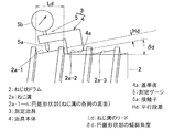
この発明の一実施形態を図1と共に説明する。ねじ状ドラム2は、螺旋状に続くねじ溝2aの各周の底面が円錐形状部2a−1,2,3・・・を成し、ねじ溝2aのリードがLdとされたものである。測定治具3は、底面が基準面4aとなる治具本体4、および前記基準面4aに対する垂直方向の距離を測定する測定ゲージ5を備える。測定ゲージ5は、治具本体4に上記基準面4aに対する垂直方向の移動が可能な状態で保持された針状測定子5aと、この測定子5aの移動距離を示すメータ5bとよりなる。
An embodiment of the present invention will be described with reference to FIG. The screw-
同図に示すように、基準面4aを円錐形状部2a−2の表面に当て、隣接する円錐形状部2a−1に測定子5aを当て、このときの測定子5aを円錐形状部2a−1に当てるに要する基準面4aに対する距離をメータ5bから読み取り、これを円錐形状部2a−1,2a−2間の平行段差Hdとする。ねじリードLdは、設計値として予め定められているから、円錐形状部の傾斜角度δdは次式(2)により求められる。
δd=sin-1(Hd/Ld) ……(2)
As shown in the figure, the
δd = sin −1 (Hd / Ld) (2)
上記平行段差Hdの測定は、基準面4aを円錐形状部2a−2の表面に当てた上で隣接する円錐形状部2a−1に測定子5aを当てるだけでなされるから、その操作は極めて容易であり、円錐形状部に基準面4aを当てることができれば、その長さに影響を受けずに正確に測定することができる。この平行段差Hdの測定に際しては、治具本体4または測定ゲージ5を、ねじ状ドラム2の円周方向に振りながら測定し、その測定値の最大値を平行段差Hdとする。この最大値は、ねじ溝2aの表面の接線位置での測定値に相当することになるから、得られた平行段差値Hdは、高度に正確なものである。
The parallel level difference Hd is measured simply by placing the
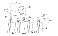
図2は、図1に示す例とは、測定治具3の向きを逆にして測定する方法である。基準面4aを円錐形状部2a−1の表面に当て、隣接する円錐形状部2a−2に測定子5aを当て、このときの測定子5aの基準面4aに対する距離をメータ5bから読み取り、これを円錐形状部2a−1,2a−2間の平行段差Hdとする。この場合も、上記数式(2)により、円錐形状部の傾斜角度δdを求めることができる。
FIG. 2 is a method for measuring the
図1および図2は、隣接する円錐形状部2a−1,2a−2に跨るように測定治具3をセットして、両円錐形状部2a−1,2a−2間の平行段差Hdを測定し、円錐形状部の傾斜角度δdを求めているが、図3に示すように、n個(図3では3個)離れた円錐形状部に測定治具3をセットしてこれらの円錐形状部間の平行段差Hdを測定することによって円錐形状部の傾斜角度δdを求めるようにしても良い。この場合は、n個分のリードLdにおいて測定することになるから、円錐形状部の傾斜角度δdは数式(3)によって求めることができる。
δd=sin-1{Hd/(n・Ld)} ……(3)
1 and 2, the
δd = sin −1 {Hd / (n · Ld)} (3)
また、測定される平行段差Hdは、n個分の円錐形状部の平行段差であり、このように測定範囲を広くすることにより、数式(3)中のHd/(n・Ld)は、平均値を求めることに等しく、これによって、より精度の高い円錐形状部の傾斜角度δdを求めることができる。 Moreover, the parallel step Hd to be measured is a parallel step of n cone-shaped portions, and thus, by widening the measurement range, Hd / (n · Ld) in Equation (3) is an average. This is equivalent to obtaining the value, and thereby, the inclination angle δd of the cone-shaped portion with higher accuracy can be obtained.
図9および図10に示すねじ研削盤50によってねじ状ドラム2を研削加工するに際して、上記のような測定方法によってその円錐形状部の傾斜角度を随時測定しながら研削加工が行なわれるようにした場合は、所定の円錐形状部の傾斜角度を高精度に備えたねじ状ドラム2が得られる。このように作製されたねじ状ドラム2は、図5および図6に示すセンタレス研削装置30のねじ状回転軸ドラム31や、図7および図8に示す超仕上げ加工装置40のねじ状回転軸ドラム41,42としてこれらの装置に組み込まれ、図4に示すテーパころ軸受用テーパころ1の研削加工や仕上げ加工に供される。したがって、これらセンタレス研削装置30や超仕上げ加工装置40によって得られるテーパころ1は、極めて精度の高いものであり、テーパころ軸受の信頼性の向上に大きく寄与する。
When the threaded
なお、上記実施形態では、テーパころ軸受用テーパころの外径面をセンタレス研削加工や超仕上げ加工する際に用いられるねじ状ドラムにおける円錐形状部の傾斜角度を測定する方法について述べたが、その他の加工装置に用いられる同様のねじ状ドラムにおける円錐形状部の傾斜角度の測定にも適用しても良い。 In the above embodiment, the method for measuring the inclination angle of the conical portion in the threaded drum used when the outer diameter surface of the tapered roller for the tapered roller bearing is subjected to centerless grinding or superfinishing is described. You may apply also to the measurement of the inclination-angle of the cone-shaped part in the same screw-shaped drum used for the processing apparatus of (ii).
2…ねじ状ドラム
2a…ねじ溝
2a−1〜n…円錐形状部(ねじ溝の各周の底面)
3…測定治具
4…治具本体
4a…基準面
5…測定ゲージ
5a…測定子
Hd…平行段差
Ld…ねじ溝のリード
δd…円錐形状部の傾斜角度
2 ... Screw-shaped
3 ... Measuring
Claims (3)
任意の円錐形状部から他の任意の円錐形状部までの平行段差を測定し、この平行段差の測定値とねじ溝のリードとから円錐形状部の傾斜角度を求めることを特徴とするねじ状ドラム円錐形状部傾斜角度測定方法。 A screw drum in which the bottom surface of each circumference of the screw groove following the spiral forms a cone-shaped portion, and is a method for measuring an inclination angle of the cone-shaped portion,
A screw-like drum characterized by measuring a parallel step from an arbitrary cone-shaped portion to another arbitrary cone-shaped portion, and obtaining an inclination angle of the cone-shaped portion from a measured value of the parallel step and a lead of a thread groove Cone-shaped portion inclination angle measurement method.
基準面を有する治具本体および前記基準面に対する垂直方向の距離を測定する測定ゲージを備えた測定治具を用い、この測定治具の前記基準面を前記ねじ状ドラムの任意の円錐形状部に当て、他の任意の円錐形状部に前記測定ゲージの測定子を当て、前記基準面を当てた円錐形状部と測定ゲージを当てた円錐形状部との平行段差を測定することにより、この平行段差の測定値とねじ溝のリードとから円錐形状部の傾斜角度を求めることを特徴とするねじ状ドラム円錐形状部傾斜角度測定方法。 A screw drum in which the bottom surface of each circumference of the screw groove following the spiral forms a cone-shaped portion, and is a method for measuring an inclination angle of the cone-shaped portion,
Using a jig body having a reference surface and a measurement jig having a measurement gauge for measuring a distance in the vertical direction with respect to the reference surface, the reference surface of the measurement jig is formed into an arbitrary conical shape portion of the screw drum. By applying a measuring element of the measurement gauge to any other cone-shaped part, and measuring the parallel step between the cone-shaped part applied with the reference surface and the cone-shaped part applied with the measurement gauge, A method for measuring a tilt angle of a cone-shaped portion of a threaded drum, wherein the tilt angle of the cone-shaped portion is obtained from the measured value of the screw and the lead of the thread groove.
Priority Applications (1)
| Application Number | Priority Date | Filing Date | Title |
|---|---|---|---|
| JP2006242272A JP4986552B2 (en) | 2006-09-07 | 2006-09-07 | Measuring method of inclination angle of conical part of threaded drum |
Applications Claiming Priority (1)
| Application Number | Priority Date | Filing Date | Title |
|---|---|---|---|
| JP2006242272A JP4986552B2 (en) | 2006-09-07 | 2006-09-07 | Measuring method of inclination angle of conical part of threaded drum |
Publications (2)
| Publication Number | Publication Date |
|---|---|
| JP2008064582A JP2008064582A (en) | 2008-03-21 |
| JP4986552B2 true JP4986552B2 (en) | 2012-07-25 |
Family
ID=39287427
Family Applications (1)
| Application Number | Title | Priority Date | Filing Date |
|---|---|---|---|
| JP2006242272A Expired - Fee Related JP4986552B2 (en) | 2006-09-07 | 2006-09-07 | Measuring method of inclination angle of conical part of threaded drum |
Country Status (1)
| Country | Link |
|---|---|
| JP (1) | JP4986552B2 (en) |
Families Citing this family (3)
| Publication number | Priority date | Publication date | Assignee | Title |
|---|---|---|---|---|
| JP4986558B2 (en) * | 2006-09-20 | 2012-07-25 | Ntn株式会社 | Threaded crowning drum shape measurement method |
| CN103568065B (en) * | 2013-10-29 | 2016-08-17 | 南通恒康数控机械股份有限公司 | A kind of sponge cutting machine is based on servomotor detection and the control method of fine setting guide rail parallelism |
| CN103940322A (en) * | 2014-03-19 | 2014-07-23 | 潍柴动力股份有限公司 | Detection tool and method for measuring conical surface height of valve seat ring |
Family Cites Families (3)
| Publication number | Priority date | Publication date | Assignee | Title |
|---|---|---|---|---|
| US4947555A (en) * | 1989-02-10 | 1990-08-14 | Allen Gauge & Tool Company | Hand held pitch diameter gauge |
| JP3971968B2 (en) * | 2002-07-05 | 2007-09-05 | 株式会社ミツトヨ | Helix shape analyzing method and helix shape analyzing apparatus |
| UA82694C2 (en) * | 2003-06-06 | 2008-05-12 | Sumitomo Metal Ind | Threaded joint for steel pipes |
-
2006
- 2006-09-07 JP JP2006242272A patent/JP4986552B2/en not_active Expired - Fee Related
Also Published As
| Publication number | Publication date |
|---|---|
| JP2008064582A (en) | 2008-03-21 |
Similar Documents
| Publication | Publication Date | Title |
|---|---|---|
| US9151588B2 (en) | Method of measuring a circular shape characteristic and circular shape characteristic measuring device and program | |
| JP5954119B2 (en) | Grinding wheel centering method in screw grinder and measuring device for centering | |
| CN109059766B (en) | Method for detecting inner ring groove position of deep groove ball bearing | |
| JP2016159397A5 (en) | Groove grinding apparatus, groove processing method, and ball bearing manufacturing method | |
| CN110579199A (en) | Method and device for measuring bar straightness | |
| JP4986552B2 (en) | Measuring method of inclination angle of conical part of threaded drum | |
| JP2010194623A (en) | Thread grinding machine and thread groove grinding method | |
| JP2013152195A (en) | Shape measuring method and measuring apparatus for object | |
| JP2004130512A (en) | Method of measuring the parameters of the surface to be machined simultaneously with the machining | |
| JP4986558B2 (en) | Threaded crowning drum shape measurement method | |
| JP6383632B2 (en) | Threaded grinding wheel dressing method | |
| JP2019157919A (en) | Bearing adjustment assisting device and bearing adjustment assisting method | |
| JP6893850B2 (en) | Rolling bearing squareness measuring device and rolling bearing squareness measuring method | |
| JP2017207436A (en) | Outer diameter dimension measurement method and jig for outer diameter dimension measurement | |
| JP5471243B2 (en) | Machining layer detection device, machining layer detection method, and centerless grinding machine | |
| RU2166729C1 (en) | Method of check of shape and diameters of inner sections of large- sized cylindrical parts | |
| KR101288968B1 (en) | Apparatus for measuring diameter of object and method for measuring the same | |
| JP6398488B2 (en) | Apparatus and method for measuring surface roughness of raceway in rolling bearing | |
| JP6786934B2 (en) | Grinding burn inspection method and grinding burn inspection equipment for workpieces | |
| JP2009113161A (en) | Grinding method and grinder | |
| CN108020128A (en) | A kind of measuring adjustable type fulcrum bearing of taper roll bearing axial error | |
| JP2020142328A (en) | Grinding method for silicon single crystal ingot | |
| JP7348037B2 (en) | processing equipment | |
| JP6186739B2 (en) | Grinding machine and grinding method | |
| JP6107212B2 (en) | Article shape measuring method and measuring apparatus |
Legal Events
| Date | Code | Title | Description |
|---|---|---|---|
| A621 | Written request for application examination |
Free format text: JAPANESE INTERMEDIATE CODE: A621 Effective date: 20090828 |
|
| TRDD | Decision of grant or rejection written | ||
| A01 | Written decision to grant a patent or to grant a registration (utility model) |
Free format text: JAPANESE INTERMEDIATE CODE: A01 Effective date: 20120424 |
|
| A01 | Written decision to grant a patent or to grant a registration (utility model) |
Free format text: JAPANESE INTERMEDIATE CODE: A01 |
|
| A61 | First payment of annual fees (during grant procedure) |
Free format text: JAPANESE INTERMEDIATE CODE: A61 Effective date: 20120424 |
|
| R150 | Certificate of patent or registration of utility model |
Ref document number: 4986552 Country of ref document: JP Free format text: JAPANESE INTERMEDIATE CODE: R150 Free format text: JAPANESE INTERMEDIATE CODE: R150 |
|
| FPAY | Renewal fee payment (event date is renewal date of database) |
Free format text: PAYMENT UNTIL: 20150511 Year of fee payment: 3 |
|
| R250 | Receipt of annual fees |
Free format text: JAPANESE INTERMEDIATE CODE: R250 |
|
| R250 | Receipt of annual fees |
Free format text: JAPANESE INTERMEDIATE CODE: R250 |
|
| R250 | Receipt of annual fees |
Free format text: JAPANESE INTERMEDIATE CODE: R250 |
|
| R250 | Receipt of annual fees |
Free format text: JAPANESE INTERMEDIATE CODE: R250 |
|
| R250 | Receipt of annual fees |
Free format text: JAPANESE INTERMEDIATE CODE: R250 |
|
| LAPS | Cancellation because of no payment of annual fees |


