JP4984875B2 - Lens array - Google Patents

Lens array Download PDF

Info

Publication number
JP4984875B2
JP4984875B2 JP2006341595A JP2006341595A JP4984875B2 JP 4984875 B2 JP4984875 B2 JP 4984875B2 JP 2006341595 A JP2006341595 A JP 2006341595A JP 2006341595 A JP2006341595 A JP 2006341595A JP 4984875 B2 JP4984875 B2 JP 4984875B2
Authority
JP
Japan
Prior art keywords
liquid
lens
common substrate
lens array
liquids
Prior art date
Legal status (The legal status is an assumption and is not a legal conclusion. Google has not performed a legal analysis and makes no representation as to the accuracy of the status listed.)
Expired - Fee Related
Application number
JP2006341595A
Other languages
Japanese (ja)
Other versions
JP2008040455A (en
JP2008040455A5 (en
Inventor
雄一 高井
Current Assignee (The listed assignees may be inaccurate. Google has not performed a legal analysis and makes no representation or warranty as to the accuracy of the list.)
Sony Corp
Original Assignee
Sony Corp
Priority date (The priority date is an assumption and is not a legal conclusion. Google has not performed a legal analysis and makes no representation as to the accuracy of the date listed.)
Filing date
Publication date
Application filed by Sony Corp filed Critical Sony Corp
Priority to JP2006341595A priority Critical patent/JP4984875B2/en
Priority to US12/306,909 priority patent/US7952809B2/en
Publication of JP2008040455A publication Critical patent/JP2008040455A/en
Publication of JP2008040455A5 publication Critical patent/JP2008040455A5/ja
Application granted granted Critical
Publication of JP4984875B2 publication Critical patent/JP4984875B2/en
Expired - Fee Related legal-status Critical Current
Anticipated expiration legal-status Critical

Links

Images

Description

本発明は、エレクトロウェッティング効果(電気毛管現象)を利用したレンズアレイに関する。   The present invention relates to a lens array using an electrowetting effect (electrocapillarity).

近年、エレクトロウェッティング効果を利用した光学素子の開発が進められている。エレクトロウェッティング効果は、導電性を有する液体と電極との間に電圧を印加したときに電極表面と液体との固液界面のエネルギーが変化し、液体表面の形状が変化する現象をいう。   In recent years, development of optical elements using the electrowetting effect has been advanced. The electrowetting effect is a phenomenon in which when a voltage is applied between a conductive liquid and an electrode, the energy of the solid-liquid interface between the electrode surface and the liquid changes, and the shape of the liquid surface changes.

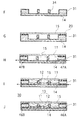
図14A,Bは、エレクトロウェッティング効果を説明する原理図である。図14Aに示すように、電極1の表面には絶縁膜2が形成されており、この絶縁膜2の上に電解液の液滴3が置かれている。絶縁膜2の表面は撥水処理が施されており、図14Aに示す無電圧状態では絶縁膜2の表面と液滴3との間の相互作用エネルギーは低く接触角θ0は大きい。ここで、接触角θ0は絶縁膜2表面と液滴3の正接線の間の角度であり、液滴3の表面張力や絶縁膜2の表面エネルギーなどの性質に依存する。   14A and 14B are principle diagrams for explaining the electrowetting effect. As shown in FIG. 14A, an insulating film 2 is formed on the surface of the electrode 1, and an electrolytic solution droplet 3 is placed on the insulating film 2. The surface of the insulating film 2 is subjected to water repellent treatment, and in the no-voltage state shown in FIG. 14A, the interaction energy between the surface of the insulating film 2 and the droplet 3 is low and the contact angle θ0 is large. Here, the contact angle θ 0 is an angle between the surface of the insulating film 2 and the tangent line of the droplet 3, and depends on properties such as the surface tension of the droplet 3 and the surface energy of the insulating film 2.

一方、図14Bに示すように、電極1と液滴3との間に所定電圧を印加すると、液滴3側の電解質イオンが絶縁膜2表面へ集中することによって電荷二重層の帯電量変化が生じ、液滴3の表面張力の変化が誘発される。この現象がエレクトロウェッティング効果であり、印加電圧の大きさによって液滴3の接触角θvが変化する。すなわち、図14Bにおいて、接触角θvは、電圧Vの関数として以下の(1)式で表される。   On the other hand, as shown in FIG. 14B, when a predetermined voltage is applied between the electrode 1 and the droplet 3, the electrolyte ions on the droplet 3 side concentrate on the surface of the insulating film 2, thereby changing the charge amount of the charge double layer. As a result, a change in the surface tension of the droplet 3 is induced. This phenomenon is an electrowetting effect, and the contact angle θv of the droplet 3 changes depending on the magnitude of the applied voltage. That is, in FIG. 14B, the contact angle θv is expressed by the following equation (1) as a function of the voltage V.

Figure 0004984875
Figure 0004984875

以上のように、電極1と液滴3との間に印加する電圧Vの大きさによって、液滴3の表面形状(曲率)が変化する。従って、液滴3をレンズ素子として用いた場合に焦点位置を電気的に制御できる光学素子を実現できることになる。   As described above, the surface shape (curvature) of the droplet 3 changes depending on the magnitude of the voltage V applied between the electrode 1 and the droplet 3. Therefore, when the droplet 3 is used as a lens element, an optical element capable of electrically controlling the focal position can be realized.

さて、このような光学素子を用いた光学装置の開発が進められている。例えば下記特許文献1には、ストロボ装置向けのレンズアレイが提案されている。これは、基板表面の撥水膜上にアレイ状に配置された絶縁性液体の液滴と導電性液体を封入して可変焦点レンズを構成したものである。この構成では、絶縁性液体と導電性液体との間の界面形状で個々のレンズが形成され、エレクトロウェッティング効果を利用して個々のレンズ形状を電気的に制御し焦点距離を変化させている。   Now, development of an optical device using such an optical element is underway. For example, Patent Document 1 below proposes a lens array for a strobe device. This is a variable focus lens configured by enclosing insulating liquid droplets and conductive liquid arranged in an array on a water-repellent film on a substrate surface. In this configuration, individual lenses are formed in the shape of the interface between the insulating liquid and the conductive liquid, and the focal length is changed by electrically controlling the individual lens shapes using the electrowetting effect. .

また、下記特許文献2には、エレクトロウェッティング効果を利用した表示装置の構成が開示されている。この表示装置は、着色液滴を収容したセルをアレイ状に配列し、セルを選択的に駆動することで所望のカラー画像を表示する。上記セルは、画像の表示部としてだけでなく、可変焦点レンズ等のレンズ素子として構成することも可能である。その構成例を図15A,Bに示す。図15は、当該レンズ素子をアレイ状に配列して構成したレンズアレイ50の概略構成を示しており、Aはレンズアレイ50を構成する共通基板54の平面図、Bはレンズアレイ50の要部断面図である。   Patent Document 2 below discloses a configuration of a display device using an electrowetting effect. In this display device, cells containing colored droplets are arranged in an array and a desired color image is displayed by selectively driving the cells. The cell can be configured not only as an image display unit but also as a lens element such as a variable focus lens. An example of the configuration is shown in FIGS. 15A and 15B. FIG. 15 shows a schematic configuration of a lens array 50 configured by arranging the lens elements in an array. A is a plan view of a common substrate 54 constituting the lens array 50, and B is a main part of the lens array 50. It is sectional drawing.

このレンズアレイ50は、導電性の第1の液体51と絶縁性の第2の液体52との界面でレンズ面を形成する複数のレンズ素子53を備えている。第1,第2の液体51,52は互いに異なる屈折率を有しており、互いに混和することなく存在している。各レンズ素子53は、透明な共通基板54と透明な蓋体55との間に形成された密閉性の液室内に二次元的に配列されており、隣接するレンズ素子53の間は仕切壁56を介して仕切られている。共通基板54の下面には透明電極膜58が形成され、共通基板54上面の第2の液体52が接する領域には撥水処理が施されている。蓋体55の下面の第1の液体51が接する領域には対向電極として透明電極膜57が形成されている。   The lens array 50 includes a plurality of lens elements 53 that form a lens surface at the interface between the conductive first liquid 51 and the insulating second liquid 52. The first and second liquids 51 and 52 have different refractive indexes and exist without being mixed with each other. Each lens element 53 is two-dimensionally arranged in an airtight liquid chamber formed between a transparent common substrate 54 and a transparent lid 55, and a partition wall 56 is provided between adjacent lens elements 53. It is partitioned through. A transparent electrode film 58 is formed on the lower surface of the common substrate 54, and a water repellent treatment is performed on a region where the second liquid 52 is in contact with the upper surface of the common substrate 54. A transparent electrode film 57 is formed as a counter electrode in a region where the first liquid 51 is in contact with the lower surface of the lid 55.

以上のような構成のレンズアレイ50は、一対の透明電極57,58間に印加する電圧を制御することによって、各レンズ素子53の第1,第2の液体51,52間の界面形状が変化する。これにより、レンズアレイ50を透過する光の焦点距離を可逆的に変化させることが可能となり、カメラのストロボ装置用の可変焦点レンズに好適に用いることができる。   In the lens array 50 configured as described above, the shape of the interface between the first and second liquids 51 and 52 of each lens element 53 changes by controlling the voltage applied between the pair of transparent electrodes 57 and 58. To do. Thereby, it becomes possible to reversibly change the focal length of the light transmitted through the lens array 50, and it can be suitably used for a variable focus lens for a strobe device of a camera.

特開2000−356708号公報JP 2000-356708 A 特開2004−252444号公報JP 2004-252444 A

しかしながら、上述した従来のレンズアレイ50においては、個々のレンズ素子53の周囲が仕切壁56で囲まれているため、レンズアレイ50の製造工程において、レンズ素子51を構成する第1,第2の液体51,52のうち、特に第2の液体52を個々のセルに一つずつ供給する作業が必要であり、素子数の増大により作業量が増加したり、セル間で供給量のバラツキが生じてレンズ素子53の特性の不均一性が発生する場合がある。   However, in the above-described conventional lens array 50, the periphery of each lens element 53 is surrounded by the partition wall 56. Therefore, in the manufacturing process of the lens array 50, the first and second lenses constituting the lens element 51 are provided. Of the liquids 51 and 52, it is particularly necessary to supply the second liquid 52 to each cell one by one, and the amount of work increases due to the increase in the number of elements, and the supply amount varies between cells. As a result, non-uniformity of the characteristics of the lens element 53 may occur.

本発明は上述の問題に鑑みてなされ、レンズ素子の特性の均一化を図ることができるレンズアレイを提供することを課題とする。   The present invention has been made in view of the above-described problems, and an object of the present invention is to provide a lens array that can achieve uniform characteristics of lens elements.

以上の課題を解決するに当たり、本発明のレンズアレイは、導電性の第1の液体と、第1の液体と屈折率が異なる絶縁性の第2の液体と、第1,第2の液体の界面でレンズ面を形成する複数のレンズ素子とを備え、印加電圧の出力制御によってレンズ素子のレンズ面が可逆的に変化するレンズアレイであって、隣接する複数のレンズ素子間が互いに液的に連通していることを特徴とする。   In solving the above-described problems, the lens array of the present invention includes a conductive first liquid, an insulating second liquid having a refractive index different from that of the first liquid, and the first and second liquids. A lens array having a plurality of lens elements forming a lens surface at an interface, wherein the lens surface of the lens element is reversibly changed by output control of an applied voltage, and a plurality of adjacent lens elements are liquidated to each other. It is characterized by communication.

本発明では、個々のレンズ素子の周囲を完全に覆う構成に代えて、隣接する複数のレンズ素子間が互いに液的に連通する構成とすることにより、レンズ素子間における第1,第2の液量のバラツキを回避し、レンズ特性の均一化を図るようにしている。   In the present invention, instead of a configuration that completely covers the periphery of each lens element, a configuration in which a plurality of adjacent lens elements are in fluid communication with each other allows the first and second liquids between the lens elements. The variation in the amount is avoided, and the lens characteristics are made uniform.

具体的に、本発明のレンズアレイにおいては、複数のレンズ素子が、共通基板と蓋体との間に形成された液室内に配列されており、第1,第2の液体のうち少なくとも一方が、隣接する複数のレンズ素子間において互いに連通している。   Specifically, in the lens array of the present invention, the plurality of lens elements are arranged in a liquid chamber formed between the common substrate and the lid, and at least one of the first and second liquids is The plurality of adjacent lens elements communicate with each other.

この場合、複数のレンズ素子は、上記共通基板上に立設した複数の突起で区画することができる。上記突起は、個々のレンズ素子の四隅位置に配置された柱状突起とすることができる。また、上記突起は、隣接するレンズ素子の間に配置され、当該隣接するレンズ素子間における液連通を許容する通路が形成された線状突起で構成することができる。   In this case, the plurality of lens elements can be partitioned by a plurality of protrusions erected on the common substrate. The protrusions can be columnar protrusions arranged at the four corner positions of each lens element. The protrusion may be a linear protrusion that is disposed between adjacent lens elements and has a passage that allows liquid communication between the adjacent lens elements.

一方、複数のレンズ素子は、液室内に配置した多孔板の非開口部で区画することができる。この多孔板は、少なくとも上記共通基板との間に液連通を許容する通路を形成する。多孔板の開口部の形状は例えば円形とされるが、これに限定されず、楕円、多角形状などでもよい。   On the other hand, the plurality of lens elements can be partitioned by a non-opening portion of a perforated plate disposed in the liquid chamber. The perforated plate forms a passage allowing liquid communication with at least the common substrate. The shape of the opening of the perforated plate is, for example, a circle, but is not limited to this, and may be an ellipse or a polygon.

以上述べたように、本発明のレンズアレイによれば、複数のレンズ素子間が互いに液的に連通しているので、レンズ素子間における第1,第2の液体の構成量のバラツキを回避し、レンズ特性の均一化を図ることができる。また、シリンジやディスペンサノズルなどの方法では液体充填できないような微小な寸法をもつ構造にも対応することができる。   As described above, according to the lens array of the present invention, since the plurality of lens elements are in fluid communication with each other, variation in the constituent amounts of the first and second liquids between the lens elements is avoided. The lens characteristics can be made uniform. Moreover, it is possible to cope with a structure having a minute dimension that cannot be filled with a liquid by a method such as a syringe or a dispenser nozzle.

以下、本発明の各実施形態について図面を参照して説明する。なお、本発明は以下の各実施形態に限定されることはなく、本発明の技術的思想に基づいて種々の変形が可能である。   Embodiments of the present invention will be described below with reference to the drawings. The present invention is not limited to the following embodiments, and various modifications can be made based on the technical idea of the present invention.

(第1の実施形態)
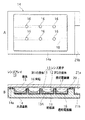
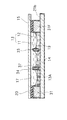
図1A,Bは本発明の第1の実施形態によるレンズアレイ10の概略構成を示しており、Aはレンズアレイ10を構成する共通基板14の平面図であり、Bはレンズアレイ10の要部断面図である。本実施形態のレンズアレイ10は、導電性の第1の液体11と絶縁性の第2の液体12との界面13Aでレンズ面を形成する複数のレンズ素子13を備えている。レンズアレイ10は、例えば照明光学系に用いられ、当該レンズアレイ10を透過する光の焦点距離を任意に変化させる可変焦点レンズとして構成されている。
(First embodiment)
1A and 1B show a schematic configuration of the lens array 10 according to the first embodiment of the present invention, where A is a plan view of a common substrate 14 constituting the lens array 10, and B is a main part of the lens array 10. It is sectional drawing. The lens array 10 of the present embodiment includes a plurality of lens elements 13 that form a lens surface at an interface 13A between the conductive first liquid 11 and the insulating second liquid 12. The lens array 10 is used as an illumination optical system, for example, and is configured as a variable focus lens that arbitrarily changes the focal length of light transmitted through the lens array 10.

第1の液体11としては、導電性を有する透明な液体が用いられ、例えば、水、電解液(塩化カリウムや塩化ナトリウム、塩化リチウム等の電解質の水溶液)、分子量の小さなメチルアルコール、エチルアルコール等のアルコール類、常温溶融塩(イオン性液体)などの有極性液体を用いることができる。   As the first liquid 11, a transparent liquid having conductivity is used. For example, water, an electrolytic solution (aqueous solution of an electrolyte such as potassium chloride, sodium chloride, or lithium chloride), methyl alcohol having a low molecular weight, ethyl alcohol, or the like. Polar liquids such as alcohols and room temperature molten salts (ionic liquids) can be used.

第2の液体12としては、絶縁性を有する透明な液体が用いられ、例えば、デカン、ドデカン、ヘキサデカンもしくはウンデカン等の炭化水素系の材料、シリコーンオイル、フッ素系の材料などの無極性溶媒を用いることができる。   As the second liquid 12, a transparent liquid having insulating properties is used. For example, a hydrocarbon-based material such as decane, dodecane, hexadecane, or undecane, a nonpolar solvent such as silicone oil or a fluorine-based material is used. be able to.

第1,第2の液体11,12は、互いに異なる屈折率を有するとともに、互いに混和することなく存在できる材料が選ばれる。具体的に、本実施形態では、第1の液体11として塩化リチウム水溶液(濃度3.66wt%、屈折率1.34)が用いられ、第2の液体12としてシリコーンオイル(GE東芝シリコーン社製TSF437、屈折率1.49)が用いられる。また、第1,第2の液体11,12は互いに同等の比重をもつことが好ましい。また、必要に応じて、第1,第2の液体11,12は着色されていてもよい。   The first and second liquids 11 and 12 are selected from materials having different refractive indexes and capable of existing without being mixed with each other. Specifically, in the present embodiment, an aqueous lithium chloride solution (concentration 3.66 wt%, refractive index 1.34) is used as the first liquid 11, and silicone oil (TSF437 manufactured by GE Toshiba Silicone Co., Ltd.) is used as the second liquid 12. , Refractive index 1.49) is used. The first and second liquids 11 and 12 preferably have the same specific gravity. Moreover, the 1st, 2nd liquids 11 and 12 may be colored as needed.

共通基板14と蓋体15との間に形成された密閉性の液室内には、第1,第2の液体11,12によって充填されているとともに、各レンズ素子13が二次元的に配列されている。共通基板14は、光学的に透明で、電気絶縁性のプラスチック材料の射出成形体あるいは切削加工体等で構成することができる。蓋体15は、光学的に透明で、電気絶縁性のプラスチック材料やガラス材料等で構成することができる。   A hermetic liquid chamber formed between the common substrate 14 and the lid 15 is filled with the first and second liquids 11 and 12, and the lens elements 13 are two-dimensionally arranged. ing. The common substrate 14 can be formed of an optically transparent, electrically-insulating plastic material injection-molded body or cutting body. The lid 15 can be made of an optically transparent and electrically insulating plastic material or glass material.

蓋体15は、共通基板14の側壁14aの上面に密封部材20を介して固定されている。蓋体15の液室側となる内面側には、端子部21aと接続される透明電極膜17が形成されている。なお、透明電極膜17としては、金属、導電性酸化物、半導体材料等を用いることができる。また、透明電極以外にも、光の透過面を避けてパターニングするようにすれば、光学的に不透明な電極材料を用いることも可能である。   The lid 15 is fixed to the upper surface of the side wall 14 a of the common substrate 14 via a sealing member 20. A transparent electrode film 17 connected to the terminal portion 21a is formed on the inner surface side that is the liquid chamber side of the lid 15. As the transparent electrode film 17, a metal, a conductive oxide, a semiconductor material, or the like can be used. In addition to the transparent electrode, it is also possible to use an optically opaque electrode material if patterning is performed while avoiding the light transmission surface.

隣接するレンズ素子13の間は、共通基板14の上面に立設された複数の突起16で区画されている。突起16は、共通基板14と一体的に形成されており、個々のレンズ素子13の四隅位置に対応して配置された柱状を有している。突起16は、例えば、共通基板14の射出成形時に同時に形成される。なお、成形した共通基板14に対して接着や圧入などの後加工によって突起16を形成してもよい。   The adjacent lens elements 13 are partitioned by a plurality of protrusions 16 erected on the upper surface of the common substrate 14. The protrusions 16 are formed integrally with the common substrate 14 and have columnar shapes arranged corresponding to the four corner positions of the individual lens elements 13. The protrusion 16 is formed at the same time when the common substrate 14 is injection molded, for example. Note that the protrusion 16 may be formed on the formed common substrate 14 by post-processing such as adhesion or press-fitting.

ここで、共通基板14の上面には透明電極膜18が形成されている。本実施形態においては、透明電極膜18は、共通基板14の側壁14aの内周面と突起16の外表面を覆うようにパターン形成されているが、共通基板14の上面全域に透明電極膜18を形成してもよい。透明電極膜18は、共通基板14の一側壁部を介して端子部21bに接続されている。なお、透明電極膜18としては、金属、導電性酸化物、半導体材料等を用いることができる。また、電極膜がパターン形成される場合には、光の透過を大きく妨げない範囲で非透明な電極膜を用いても構わない。   Here, a transparent electrode film 18 is formed on the upper surface of the common substrate 14. In the present embodiment, the transparent electrode film 18 is patterned so as to cover the inner peripheral surface of the side wall 14 a of the common substrate 14 and the outer surface of the protrusion 16, but the transparent electrode film 18 is formed on the entire upper surface of the common substrate 14. May be formed. The transparent electrode film 18 is connected to the terminal portion 21 b through one side wall portion of the common substrate 14. As the transparent electrode film 18, a metal, a conductive oxide, a semiconductor material, or the like can be used. Further, when the electrode film is patterned, a non-transparent electrode film may be used as long as light transmission is not greatly hindered.

また、共通基板14の表面は、透明電極膜18を被覆するように絶縁膜19が形成されている。本実施形態では、絶縁膜19は、共通基板14の外面全域に形成されているが、例えば、共通基板14の上面側にのみ形成するだけでも構わない。   An insulating film 19 is formed on the surface of the common substrate 14 so as to cover the transparent electrode film 18. In this embodiment, the insulating film 19 is formed over the entire outer surface of the common substrate 14, but may be formed only on the upper surface side of the common substrate 14, for example.

絶縁膜19は、電気絶縁性の物質であれば特に制限されず、好適には、誘電率が比較的高い物質が選択される。また、比較的大きな静電容量を得るために絶縁膜19の膜厚は薄い方が好ましいが、絶縁強度を確保できる膜厚以上であることが必要である。誘電率の比較的高い材料としては、例えば、酸化タンタル、酸化チタンなどの金属酸化物が挙げられるが、勿論これに限定されない。絶縁膜19の形成方法も特に制限されず、スパッタ法、CVD法、蒸着法等の真空薄膜形成方法のほか、めっき法、電着法、コート法、ディップ法等の各種コーティング方法が採用可能である。   The insulating film 19 is not particularly limited as long as it is an electrically insulating material, and a material having a relatively high dielectric constant is preferably selected. In order to obtain a relatively large capacitance, it is preferable that the insulating film 19 is thin, but it is necessary that the insulating film 19 has a thickness that can ensure the insulation strength. Examples of the material having a relatively high dielectric constant include metal oxides such as tantalum oxide and titanium oxide, but of course, the material is not limited thereto. The formation method of the insulating film 19 is not particularly limited, and various coating methods such as a plating method, an electrodeposition method, a coating method, and a dip method can be employed in addition to a vacuum thin film forming method such as a sputtering method, a CVD method, and an evaporation method. is there.

また、絶縁膜19は、第2の液体12が接触する領域において撥水性を有することが好ましい。撥水膜の形成方法としては、例えばポリパラキシリレンをCVD法で成膜する方法、フッ素系のポリマーであるPVDF(ポリビニリデンフルオライド)、PTFE(ポリテトラフルオロエチレン)などの材料を共通基板14上にコーティングする方法などが挙げられる。また、高誘電率材料と撥水性材料とを複数組み合わせた積層構造で絶縁膜19を構成してもよい。   The insulating film 19 preferably has water repellency in a region where the second liquid 12 is in contact. As a method of forming the water repellent film, for example, a method of forming polyparaxylylene by a CVD method, a material such as PVDF (polyvinylidene fluoride), PTFE (polytetrafluoroethylene), which is a fluorine-based polymer, is used as a common substrate 14 or the like. Further, the insulating film 19 may be configured by a laminated structure in which a plurality of high dielectric constant materials and water repellent materials are combined.

本実施形態のレンズアレイ10は、第1の液体11が蓋体15側に、第2の液体12が共通基板14側にそれぞれ偏在した複数のレンズ素子13を備えている。各レンズ素子13は、共通基板14の側壁14a内周部及び突起16によって、それぞれの配列位置が決定される。即ち、図1Aに示した例では、側壁14aの内周部とこれに隣接する突起16の間、及び隣接する複数の突起16間において、3行4列の合計12個の四角形状のレンズ素子13が面内にアレイ状に配列される。なお、実際は、突起16は図示の例より更に多く立設されるため、レンズ素子13の配列数は更に多くなる。   The lens array 10 of this embodiment includes a plurality of lens elements 13 in which the first liquid 11 is unevenly distributed on the lid 15 side and the second liquid 12 is unevenly distributed on the common substrate 14 side. Each lens element 13 has its arrangement position determined by the inner peripheral portion of the side wall 14 a of the common substrate 14 and the protrusion 16. That is, in the example shown in FIG. 1A, a total of 12 rectangular lens elements of 3 rows and 4 columns between the inner peripheral portion of the side wall 14a and the adjacent protrusions 16 and between the adjacent protrusions 16 are provided. 13 are arranged in an array in the plane. Actually, since the protrusions 16 are more erected than the illustrated example, the number of lens elements 13 arranged is further increased.

図1Bに示す状態において、各レンズ素子13のレンズ面13Aは、第1の液体11が共通基板14の側壁14a内面又は突起16の周囲に対して所定の接触角で接することで所定の曲面形状を形成している。レンズ面13Aは側壁14a内面と突起16の間、及び突起16間をつなぐ線が稜線を描くような曲面形状を有し、四角形状の素子中央部が凹状に湾曲している。   In the state shown in FIG. 1B, the lens surface 13A of each lens element 13 has a predetermined curved surface shape when the first liquid 11 contacts the inner surface of the side wall 14a of the common substrate 14 or the periphery of the protrusion 16 at a predetermined contact angle. Is forming. The lens surface 13A has a curved surface shape in which a line connecting the inner surface of the side wall 14a and the protrusion 16 and between the protrusions 16 draws a ridge line, and a square element central portion is curved in a concave shape.

この状態で、端子部21a,21b間に電圧を印加すると、エレクトロウェッティング効果(電気毛管現象)によって、第1の液体11が側壁14a内周及び突起16の周囲に濡れ広がる。これにより、側壁14a内周及び突起16の周囲に対する第1の液体11の接触角が変化し、レンズ面13Aの形状変化を引き起こす。レンズ面13Aの形状変化は可逆的である。従って、端子部21a,21bに印加する電圧の大きさにより、各レンズ素子13のレンズ面13Aが任意に変化する。具体的に、印加電圧を大きくするとレンズ面13Aの曲率半径が大きくなり、その結果、焦点距離も大きくなる。これにより、レンズアレイ10を透過する光について当該レンズアレイ10を可変焦点レンズとして機能させることができる。   When a voltage is applied between the terminal portions 21a and 21b in this state, the first liquid 11 wets and spreads around the inner periphery of the side wall 14a and the periphery of the protrusion 16 due to the electrowetting effect (electrocapillary phenomenon). As a result, the contact angle of the first liquid 11 with respect to the inner periphery of the side wall 14a and the periphery of the protrusion 16 changes, causing a change in the shape of the lens surface 13A. The shape change of the lens surface 13A is reversible. Accordingly, the lens surface 13A of each lens element 13 is arbitrarily changed depending on the magnitude of the voltage applied to the terminal portions 21a and 21b. Specifically, when the applied voltage is increased, the radius of curvature of the lens surface 13A is increased, and as a result, the focal length is also increased. Thereby, the lens array 10 can be made to function as a variable focus lens with respect to light transmitted through the lens array 10.

そこで、本実施形態によれば、隣接する複数のレンズ素子13間において第1,第2の液体11,12が柱状の突起16間を介して互いに連通しているので、従来のように各レンズ素子の周囲を仕切壁で囲む構成に比べて、レンズ素子間の仕切形成領域をはるかに少なくすることができ、これによりレンズの有効面積を大きくすることができるとともに、透過率の向上を図ることができる。   Therefore, according to the present embodiment, the first and second liquids 11 and 12 communicate with each other via the columnar protrusions 16 between the adjacent lens elements 13, so that each lens as in the related art. Compared to a configuration in which the periphery of the element is surrounded by a partition wall, the partition formation area between the lens elements can be made much smaller, thereby increasing the effective area of the lens and improving the transmittance. Can do.

また、各レンズ素子13の形状精度を突起16の加工精度で制御することができるようになるため、レンズ素子13の形状精度を出すための加工領域を従来よりも少なくでき、レンズアレイ10の作製コストの大幅な低減を図ることができる。   In addition, since the shape accuracy of each lens element 13 can be controlled by the processing accuracy of the protrusion 16, the processing area for obtaining the shape accuracy of the lens element 13 can be reduced as compared with the conventional case, and the lens array 10 is manufactured. Costs can be significantly reduced.

更に、本実施形態によれば、隣接する複数のレンズ素子13間において第1,第2の液体11,12が互いに連通する構成であるので、第1の液体11と第2の液体12との間の界面はひとつにつながっている。そして、この界面エネルギーは最小になるように働くので、個々のレンズ素子13のバラツキは均一化される。これにより、レンズ素子13ごとの第1,第2の液体11,12の液量のバラツキを抑えることができる。また、素子単位で液量を高精度に調整する必要がなくなる。以上により、レンズアレイ10を構成する各レンズ素子13のレンズ特性を容易かつ均一化することができるとともに、レンズアレイ10の組立ても容易となる。
Furthermore, according to the present embodiment, the first and second liquids 11 and 12 communicate with each other between a plurality of adjacent lens elements 13, so that the first liquid 11 and the second liquid 12 The interface between them is connected to one. And since this interface energy works to become the minimum, the variation of the individual lens elements 13 is made uniform. Thereby, variation in the liquid amount of the first and second liquids 11 and 12 for each lens element 13 can be suppressed. In addition, it is not necessary to adjust the liquid amount with high accuracy for each element. As described above, the lens characteristics of the lens elements 13 constituting the lens array 10 can be easily and uniformized , and the lens array 10 can be easily assembled.

更に、液室内の気泡の発生が抑えられ、気泡が発生したとしても液室内の液体が素子間で連通しているため外部へ抜き易くなる。また、液室内に混入した異物も排出し易くなるという効果も有する。   Further, the generation of bubbles in the liquid chamber is suppressed, and even if bubbles are generated, the liquid in the liquid chamber communicates between the elements, so that it is easy to draw out. In addition, there is an effect that foreign matters mixed in the liquid chamber can be easily discharged.

ここで、レンズ素子13の形状、大きさ等は、突起16の形成間隔、断面形状等に応じてほぼ任意に設定することができる。例えば、突起16を図1において上下左右方向いずれも等間隔で形成することにより、平面視正方形状のレンズ素子を構成することができると同時に、同様なレンズ特性を備えたレンズアレイを構成することができる。逆に、突起16の形成間隔を領域毎に異ならせることで、異なるレンズ特性を有するレンズアレイを構成することができる。   Here, the shape, size, and the like of the lens element 13 can be set almost arbitrarily according to the formation interval, the cross-sectional shape, and the like of the protrusions 16. For example, by forming the protrusions 16 at equal intervals in the vertical and horizontal directions in FIG. 1, it is possible to form a square-shaped lens element in plan view, and at the same time, to configure a lens array having similar lens characteristics. Can do. Conversely, by varying the formation interval of the protrusions 16 for each region, a lens array having different lens characteristics can be configured.

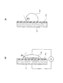
また、隣接する複数の突起16間の距離あるいは共通基板側壁14a内面とこれに隣接する突起16間の距離は、毛管長以下の長さに設定される。毛管長とは、界面張力に対して重力の影響を無視できる最大の長さをいい、導電性液体と絶縁性液体との関係においては下記(2)式で表される。   Further, the distance between the plurality of adjacent protrusions 16 or the distance between the inner surface of the common substrate side wall 14a and the protrusion 16 adjacent thereto is set to a length equal to or shorter than the capillary length. The capillary length means the maximum length that can ignore the influence of gravity on the interfacial tension, and the relationship between the conductive liquid and the insulating liquid is expressed by the following equation (2).

Figure 0004984875
Figure 0004984875

図2Aは、突起16間の距離が毛管長(κ-1)以下のときの第1,第2の液体11,12の界面形状を示している。突起16間の距離が毛管長以下のとき、第1,第2の液体11,12の界面は重力の影響を受けずに曲面形状を維持し、電気毛管現象による界面形状の制御が可能となる。これに対して、突起16間の距離が毛管長より長くなると、図2Bに示すように、重力による影響を受けて第1,第2の液体11,12の界面は中央部において平坦となり、電気毛管現象を利用した界面形状の変化が困難になる。従って、隣接する複数の突起16間の距離あるいは共通基板側壁14a内面とこれに隣接する突起16間の距離は、毛管長以下の長さに設定される必要がある。換言すると、四角形状のレンズ素子の一辺の長さ及び対角線長が毛管長以下に設定されることになる。 FIG. 2A shows the interface shape of the first and second liquids 11 and 12 when the distance between the protrusions 16 is equal to or shorter than the capillary length (κ −1 ). When the distance between the protrusions 16 is equal to or shorter than the capillary length, the interface between the first and second liquids 11 and 12 maintains a curved surface shape without being affected by gravity, and the interface shape can be controlled by electrocapillarity. . On the other hand, when the distance between the protrusions 16 becomes longer than the capillary length, the interface between the first and second liquids 11 and 12 becomes flat at the center due to the influence of gravity, as shown in FIG. It becomes difficult to change the interface shape using capillary action. Therefore, the distance between the plurality of adjacent protrusions 16 or the distance between the inner surface of the common substrate side wall 14a and the protrusion 16 adjacent thereto needs to be set to a length equal to or shorter than the capillary length. In other words, the length and the diagonal length of one side of the rectangular lens element are set to be equal to or shorter than the capillary length.

毛管長は、界面を構成する2つの媒体の種類によって異なる。図3は、2媒体が水と空気、水と油の場合のそれぞれの界面張力、密度差、毛管長を比較して示している。水と空気の場合の毛管長は2.7mmであるのに対して、水と油の場合の毛管長は15.2mmである。従って、上述の第1,第2の液体11,12の密度差(比重差)を0.0129まで小さくすることで、15.2mmまで突起16の間隔を広げられることになる。   The capillary length varies depending on the types of the two media constituting the interface. FIG. 3 shows a comparison of the interfacial tension, density difference, and capillary length when the two media are water and air and water and oil. The capillary length for water and air is 2.7 mm, while the capillary length for water and oil is 15.2 mm. Therefore, by reducing the density difference (specific gravity difference) between the first and second liquids 11 and 12 to 0.0129, the interval between the protrusions 16 can be increased to 15.2 mm.

柱状の突起16の断面形状は図示の例では円形とされるが、勿論これに限られず、楕円体、三角系や四角形等の多角形状であってもよい。また、突起16の高さは、図1Bに示したように共通基板14の側壁14aの高さよりも低くする場合に限らず、側壁14aの高さと一致させてもよい。この場合、突起16の上端が蓋体15に接するため、レンズアレイ10の面積を大きくしても外力等によって基板14と蓋体15との間隔が変化することが防止される。従って、レンズアレイ10の大きさや使用条件によって、突起16の上端と蓋体15との間に隙間を設けてもよいし、突起16の幾つかだけを蓋体15と接する高さに形成するようにしてもよい。
The cross-sectional shape of the columnar protrusion 16 is circular in the illustrated example, but of course it is not limited to this, and may be an ellipsoid, a polygonal shape such as a triangular system or a quadrangle. The height of the protrusion 16 is not limited to the height of the side wall 14a of the common substrate 14 as shown in FIG. 1B, but may be the same as the height of the side wall 14a. In this case, since the upper end of the protrusion 16 is in contact with the lid 15, even if the area of the lens array 10 is increased, the distance between the substrate 14 and the lid 15 is prevented from being changed by an external force or the like. Therefore, a gap may be provided between the upper end of the projection 16 and the lid 15 depending on the size of the lens array 10 and usage conditions, or only some of the projections 16 may be formed at a height in contact with the lid 15. It may be.

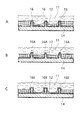
更に、突起16の側面は基板14に対して垂直である場合に限らず、先細り形状あるいは先太り形状としてもよい。図4は突起形状の相違による第1,第2の液体11,12の界面の初期形状を比較して示す。図4Aは直筒形状の突起16の例を示し、図4Bは先細り形状の突起16Aの例を示し、図4Cは先太り形状の突起16Bの例を示している。   Further, the side surfaces of the protrusions 16 are not limited to being perpendicular to the substrate 14, and may be tapered or tapered. FIG. 4 shows a comparison of the initial shapes of the interfaces of the first and second liquids 11 and 12 due to the difference in projection shape. 4A shows an example of a straight cylindrical protrusion 16, FIG. 4B shows an example of a tapered protrusion 16A, and FIG. 4C shows an example of a tapered protrusion 16B.

突起側面に対する第1の液体11の接触角は同一であるが、突起側面の形成角度によって2液体の界面形状が大きく変化する様子がわかる。先細り形状の突起16Aの場合は直筒形状の突起16と比較して界面の曲率が小さくなり、先太り形状の突起16Bの場合は直筒形状の突起16と比較して界面の曲率が大きくなる。突起形状を最適化することにより、レンズアレイの可変焦点範囲を任意に調整することが可能となる。   Although the contact angle of the 1st liquid 11 with respect to a protrusion side is the same, it turns out that the interface shape of two liquids changes with the formation angles of a protrusion side. In the case of the tapered protrusion 16A, the curvature of the interface is smaller than that of the straight cylindrical protrusion 16, and in the case of the tapered protrusion 16B, the curvature of the interface is larger than that of the straight cylindrical protrusion 16. By optimizing the projection shape, the variable focal range of the lens array can be arbitrarily adjusted.

(第2の実施形態)
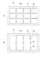
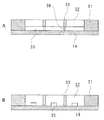
図5A,Bは本発明の第2の実施形態を示している。本実施形態では、個々のレンズ素子の形成範囲を区画する突起が線状に形成されている点で、上述の第1の実施形態と異なっている。なお、図において上述の第1の実施形態と対応する部分については同一の符号を付し、その詳細な説明は省略するものとする。
(Second Embodiment)
5A and 5B show a second embodiment of the present invention. This embodiment is different from the first embodiment described above in that the projections that define the formation ranges of the individual lens elements are formed in a linear shape. In the figure, portions corresponding to those of the first embodiment described above are denoted by the same reference numerals, and detailed description thereof is omitted.

図5Aは、レンズアレイを構成する共通基板14の平面図であり、線状の突起26を2次元の格子状に配列して、隣接する複数の突起26間において3行×4列の合計12個の四角形状のレンズ素子形成領域を区画した例を示している。突起26には、隣接するレンズ素子間における液連通を許容するための通路27が形成されている。通路27は、直線的に並ぶ複数の突起26間に形成されているが、突起26の一部を切り欠いて形成してもよい。   FIG. 5A is a plan view of the common substrate 14 constituting the lens array, in which linear protrusions 26 are arranged in a two-dimensional lattice pattern, and a total of 3 rows × 4 columns 12 between a plurality of adjacent protrusions 26. An example in which a rectangular lens element formation region is partitioned is shown. The protrusion 26 is formed with a passage 27 for allowing liquid communication between adjacent lens elements. The passage 27 is formed between the plurality of linearly arranged protrusions 26, but may be formed by cutting out a part of the protrusion 26.

図5Bは、レンズアレイを構成する共通基板14の平面図であり、線状の突起26を1次元の格子状に配列して、隣接する複数の突起26間において1行×4列の合計4本のシリンドリカルレンズ(あるいはレンチキュラーレンズ)の形成領域を区画した例を示している。この例においても、隣接するレンズ素子間における液連通を許容するための通路27が形成されている。   FIG. 5B is a plan view of the common substrate 14 constituting the lens array, in which linear protrusions 26 are arranged in a one-dimensional lattice pattern, and a total of 4 in 1 row × 4 columns between a plurality of adjacent protrusions 26. An example is shown in which a formation region of a cylindrical lens (or lenticular lens) is partitioned. Also in this example, a passage 27 for allowing liquid communication between adjacent lens elements is formed.

これらの例においても、上述の実施形態と同様に、レンズの有効面積の増大と透過率の向上を図れるようになる。また、素子間における液量のバラツキを抑制してレンズ特性の均一化を図れるようになる。   In these examples, as in the above-described embodiment, the effective area of the lens can be increased and the transmittance can be improved. In addition, it is possible to make the lens characteristics uniform by suppressing variations in the liquid amount between the elements.

(第3の実施形態)
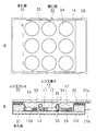
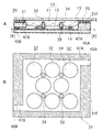
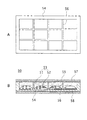
図6A,Bは本発明の第3の実施形態によるレンズアレイ30の概略構成を示しており、Aはレンズアレイ30の内部構造を示す平面図、Bはレンズアレイ30の要部断面図である。なお、図において上述の第1の実施形態と対応する部分については同一の符号を付し、その詳細な説明は省略するものとする。
(Third embodiment)
6A and 6B show a schematic configuration of the lens array 30 according to the third embodiment of the present invention, where A is a plan view showing the internal structure of the lens array 30, and B is a cross-sectional view of the main part of the lens array 30. FIG. . In the figure, portions corresponding to those of the first embodiment described above are denoted by the same reference numerals, and detailed description thereof is omitted.

上述の第1の実施形態と同様に、共通基板14と蓋体15との間に形成された液室内には、第1,第2の液体11,12からなる複数のレンズ素子13が二次元的に配列されている。なお、本実施形態において、共通基板14は、蓋体15と同様に、その表面及び裏面が平坦な透明な板材で構成されている。   Similar to the first embodiment described above, a plurality of lens elements 13 composed of the first and second liquids 11 and 12 are two-dimensionally arranged in the liquid chamber formed between the common substrate 14 and the lid 15. Are arranged. In the present embodiment, the common substrate 14 is formed of a transparent plate material whose front and back surfaces are flat, similarly to the lid body 15.

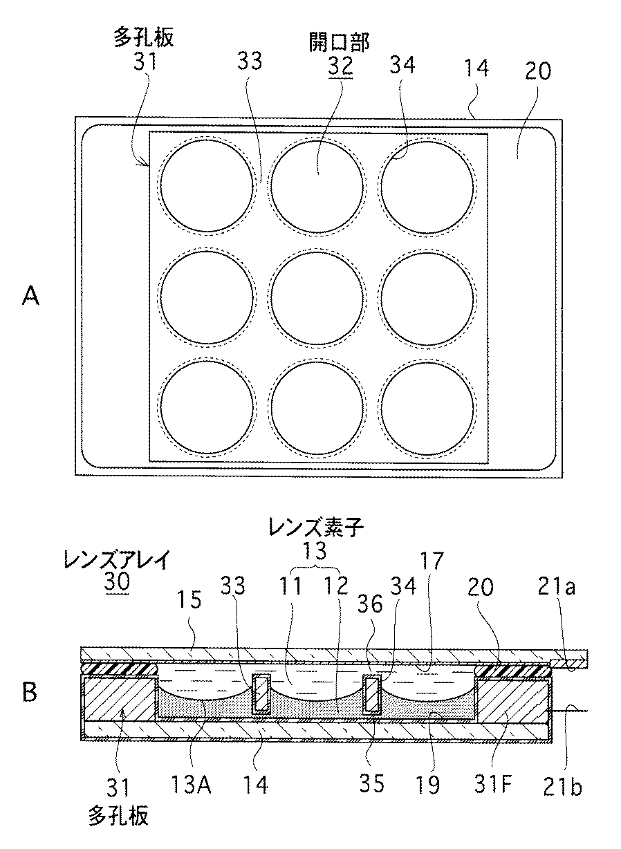
本実施形態では、共通基板14と蓋体15との間に多孔板31を配置し、この多孔板31の面内に形成された複数の円形の開口部32内に個々のレンズ素子13を収容し、多孔板31の非開口部33によって各々のレンズ素子13を区画するようにしている。多孔板31と共通基板14との間には、隣接する開口部32間の液連通を許容する通路35が形成されており、多孔板31と蓋体15との間には、隣接する開口部32間の液連通を許容する通路36が形成されている。一方の通路35は、多孔板31の共通基板34と対向する側の面を凹状に形成することで形成され、他方の通路36は、液室構成時における密封部材20の形成厚で形成される。   In the present embodiment, a porous plate 31 is arranged between the common substrate 14 and the lid 15, and each lens element 13 is accommodated in a plurality of circular openings 32 formed in the plane of the porous plate 31. Each lens element 13 is partitioned by the non-opening portion 33 of the perforated plate 31. Between the perforated plate 31 and the common substrate 14, a passage 35 that allows liquid communication between the adjacent openings 32 is formed, and between the perforated plate 31 and the lid 15, adjacent openings A passage 36 that allows liquid communication between 32 is formed. One passage 35 is formed by forming a concave surface of the porous plate 31 on the side facing the common substrate 34, and the other passage 36 is formed by the formation thickness of the sealing member 20 when the liquid chamber is configured. .

多孔板31は、その周囲の枠部31Fの下面が共通基板14上に接合されているとともに、この枠部31Fの上面が密封部材20を介して蓋体15に密着固定されている。本実施形態において、多孔板31は、シリコン基板等の半導体材料で構成されているが、これ以外にも、金属板や、ガラス、セラミックス、樹脂等の絶縁性基板で構成されていても構わない。絶縁性樹脂の場合は、導電性材料による電極膜を形成する。多孔板31は端子部21bを介して外部の電圧源(図示略)に接続されている。多孔板31の表裏面および開口部32の周縁は、絶縁膜34で被覆されており、導電性の第1の液体11と当該多孔板31との間の電気的絶縁が図られている。   The perforated plate 31 has a lower surface of the surrounding frame portion 31F bonded to the common substrate 14, and an upper surface of the frame portion 31F is closely fixed to the lid 15 via the sealing member 20. In this embodiment, the perforated plate 31 is made of a semiconductor material such as a silicon substrate, but may be made of an insulating substrate such as a metal plate, glass, ceramics, or resin. . In the case of an insulating resin, an electrode film made of a conductive material is formed. The perforated plate 31 is connected to an external voltage source (not shown) via the terminal portion 21b. The front and back surfaces of the perforated plate 31 and the periphery of the opening 32 are covered with an insulating film 34, so that electrical insulation between the conductive first liquid 11 and the perforated plate 31 is achieved.

絶縁膜34は、撥水性、透明性、所定の絶縁耐圧、均一な膜厚・膜質であれば、特に材料は限られない。レンズ素子13の動作電圧は、絶縁膜34の厚さと誘電率によって変化する。絶縁膜34の膜厚が薄く、誘電率が高くなるほど動作電圧は低くなる。絶縁膜34の形成は、多孔板31と共通基板14の接合前に行ってもよいし、接合後に行ってもよい。   The insulating film 34 is not particularly limited as long as it has water repellency, transparency, predetermined withstand voltage, and uniform film thickness / film quality. The operating voltage of the lens element 13 varies depending on the thickness and dielectric constant of the insulating film 34. The operating voltage decreases as the thickness of the insulating film 34 decreases and the dielectric constant increases. The insulating film 34 may be formed before the porous plate 31 and the common substrate 14 are bonded or after the bonding.

多孔板31と共通基板14との間の接合は、多孔板31及び共通基板14の材質等によって各種接合法を採用することができる。例えば、上述のように多孔板31がシリコン基板で構成され、共通基板14がガラス材料で構成される場合には、多孔板31と共通基板14との間は陽極接合法により接合することができる。また、多孔板31及び共通基板14がともに合成樹脂で構成される場合には、拡散接合法や超音波接合法等が採用可能である。更に、接着剤を用いた接合法も適用可能であり、多孔板31及び共通基板14の材質の組合せを問わず使用することができる。   For joining between the perforated plate 31 and the common substrate 14, various joining methods can be adopted depending on the material of the perforated plate 31 and the common substrate 14. For example, when the porous plate 31 is made of a silicon substrate and the common substrate 14 is made of a glass material as described above, the porous plate 31 and the common substrate 14 can be bonded by an anodic bonding method. . Further, when both the porous plate 31 and the common substrate 14 are made of synthetic resin, a diffusion bonding method, an ultrasonic bonding method, or the like can be employed. Furthermore, a bonding method using an adhesive is also applicable, and any combination of materials for the perforated plate 31 and the common substrate 14 can be used.

上述した構成の本実施形態のレンズアレイ30においては、第1の実施形態と同様に、第1の液体11が蓋体15側に、第2の液体12が共通基板14側にそれぞれ偏在した複数のレンズ素子13を備えている。各レンズ素子13は、多孔板31の開口部32の形成位置によってそれぞれの配列位置が決定され、図6Aに示した例においては、3行×3列の合計9個の円形状のレンズ素子13が面内にアレイ状に配列される。なお、レンズ素子13の配列数はこれに限定されず、開口部32の形成数に合わせてレンズ素子13の配列数を任意に調整することができる。   In the lens array 30 of the present embodiment having the above-described configuration, a plurality of first liquids 11 are unevenly distributed on the lid 15 side and the second liquid 12 is unevenly distributed on the common substrate 14 side, as in the first embodiment. The lens element 13 is provided. The arrangement positions of the lens elements 13 are determined depending on the positions where the openings 32 of the perforated plate 31 are formed. In the example shown in FIG. 6A, a total of nine circular lens elements 13 in 3 rows × 3 columns. Are arranged in an array in the plane. The number of lens elements 13 arranged is not limited to this, and the number of lens elements 13 arranged can be arbitrarily adjusted according to the number of openings 32 formed.

図6Bに示す状態において、各レンズ素子13のレンズ面13Aは、第1の液体11が多孔板31の開口部32の周縁に対して所定の接触角で接することで所定の曲面形状を形成している。レンズ面13Aは、素子中央部が凹状に湾曲した曲面形状を有している。   In the state shown in FIG. 6B, the lens surface 13A of each lens element 13 forms a predetermined curved surface shape by the first liquid 11 contacting the peripheral edge of the opening 32 of the porous plate 31 at a predetermined contact angle. ing. The lens surface 13A has a curved surface shape in which the central portion of the element is curved in a concave shape.

この状態で、端子部21a,21b間に電圧を印加すると、エレクトロウェッティング効果(電気毛管現象)によって、第1の液体11が開口部32の周縁部に濡れ広がる。これにより、開口部32の周縁部に対する第1の液体11の接触角が変化し、レンズ面13Aの形状変化を引き起こす。レンズ面13Aの形状変化は可逆的である。従って、端子部21a,21bに印加する電圧の大きさにより、各レンズ素子13のレンズ面13Aが任意に変化する。具体的に、印加電圧を大きくするとレンズアレイ30を透過する光について当該レンズアレイ30を可変焦点レンズとして機能させることができる。   In this state, when a voltage is applied between the terminal portions 21a and 21b, the first liquid 11 wets and spreads around the peripheral portion of the opening 32 due to an electrowetting effect (electrocapillarity). Thereby, the contact angle of the 1st liquid 11 with respect to the peripheral part of the opening part 32 changes, and causes the shape change of 13 A of lens surfaces. The shape change of the lens surface 13A is reversible. Accordingly, the lens surface 13A of each lens element 13 is arbitrarily changed depending on the magnitude of the voltage applied to the terminal portions 21a and 21b. Specifically, when the applied voltage is increased, the lens array 30 can function as a variable focus lens with respect to light transmitted through the lens array 30.

本実施形態によれば、共通基板14と蓋体15との間に多孔板31を配置し、当該多孔板31の非開口部33で複数のレンズ素子13を区画するとともに、通路35,36を介して、隣接する複数のレンズ素子13間の液な連通を図るようにしている。これにより、レンズ素子13ごとの第1,第2の液体11,12の液量のバラツキを抑えることができる。また、素子単位で液量を高精度に調整する必要がなくなる。以上により、レンズアレイ30を構成する各レンズ素子13のレンズ特性を容易かつ均一化することができるとともに、レンズアレイ30の組立ても容易となる。
According to the present embodiment, the porous plate 31 is disposed between the common substrate 14 and the lid 15, the plurality of lens elements 13 are partitioned by the non-opening portion 33 of the porous plate 31, and the passages 35 and 36 are formed. through it, so that achieve the liquid specific communication between a plurality of lens elements 13 adjacent to each other. Thereby, variation in the liquid amount of the first and second liquids 11 and 12 for each lens element 13 can be suppressed. In addition, it is not necessary to adjust the liquid amount with high accuracy for each element. As described above, the lens characteristics of the lens elements 13 constituting the lens array 30 can be easily and uniformized , and the lens array 30 can be easily assembled.

本実施形態において、開口部32を構成する多孔板31の厚さは、印加電圧の設定範囲においてレンズ面13Aの形状変化を妨げない程度の厚さとされる。また、開口部32の形状は円形に限らず、四角形等の多角形、楕円形などの他の幾何学的形状でも構わない。なお、開口部32を円形とすることで、レンズ素子13のレンズとしての有効面積を大きくすることができるので、光学特性に優れたレンズ素子13を構成することができる。また、開口部32を多角形状とすることにより、開口部32の開口面積を大きくすることができる。開口部32の大きさは、第1の実施形態において説明したように、毛管長以下の長さに設定されることが好ましい。   In the present embodiment, the thickness of the perforated plate 31 constituting the opening 32 is set to a thickness that does not hinder the shape change of the lens surface 13A in the set range of the applied voltage. The shape of the opening 32 is not limited to a circle, and may be other geometric shapes such as a polygon such as a quadrangle, and an ellipse. In addition, since the effective area as a lens of the lens element 13 can be enlarged by making the opening part 32 circular, the lens element 13 excellent in optical characteristics can be configured. Moreover, the opening area of the opening part 32 can be enlarged by making the opening part 32 into a polygonal shape. As described in the first embodiment, the size of the opening 32 is preferably set to a length equal to or shorter than the capillary length.

また、開口部32の形成位置は、図6Aに示したように縦方向および横方向に整列配置させる場合に限らず、例えば図7Aに示すように、行方向に整列する開口部32の間に次の行の開口部32がそれぞれ位置するような開口部32の稠密配置構造を採用してもよい。   In addition, the formation position of the openings 32 is not limited to the case where the openings 32 are aligned in the vertical direction and the horizontal direction as shown in FIG. 6A. For example, as shown in FIG. 7A, the openings 32 are formed between the openings 32 aligned in the row direction. You may employ | adopt the dense arrangement structure of the opening part 32 so that the opening part 32 of the next line may each be located.

一方、多孔板32をガラスやプラスチック、セラミック等の絶縁性材料で構成する場合には、図7Bに示すように、各々の開口部32の周縁部に、電極37としてITO等の透明導電膜をパターン形成し、図8に示すように電極37を撥水性の絶縁膜34で被覆すればよい。電極37は、各開口部32間で網目に引き回され、多孔板31の枠部31Fの外面に形成した連絡部37Pを介して、共通基板14の表面の一側部に形成した端子部21bに共通に接続される。なお、各開口部32の電極37を各々独立して形成し、各開口部に対応して設けた端子部21bに個別に接続することで、個々のレンズ素子13を独立して駆動させることが可能となる。
On the other hand, when the perforated plate 32 is made of an insulating material such as glass, plastic, or ceramic, as shown in FIG. 7B, a transparent conductive film such as ITO is used as an electrode 37 on the periphery of each opening 32. A pattern is formed, and the electrode 37 may be covered with a water-repellent insulating film 34 as shown in FIG. The electrode 37 is drawn in a mesh shape between the openings 32 and is formed on one side of the surface of the common substrate 14 via a connecting portion 37P formed on the outer surface of the frame portion 31F of the porous plate 31. 21b is commonly connected. In addition, each lens element 13 can be driven independently by forming the electrode 37 of each opening part 32 independently, and connecting individually to the terminal part 21b provided corresponding to each opening part. It becomes possible.

また、多孔板31が共通基板14及び蓋体15に対し、それぞれ液連通用の通路35及び通路36を介して対向する構成に代えて、例えば、多孔板31と蓋体15との間を密着させ、多孔板31と共通基板14との間の通路35のみで液連通を確保する構成を採用しても構わない。   Further, instead of the configuration in which the porous plate 31 is opposed to the common substrate 14 and the lid body 15 via the liquid communication passage 35 and the passage 36, respectively, for example, the porous plate 31 and the lid body 15 are in close contact with each other. Alternatively, a configuration in which liquid communication is ensured only by the passage 35 between the perforated plate 31 and the common substrate 14 may be employed.

更に、図9Aに示すように、多孔板31と共通基板14との間に支柱38を配置することで、多孔板31と共通基板14との間のクリアランスを一定に保持でき、レンズ素子13間の液量のバラツキを防止できる。また、外部ストレスに対する耐久性の向上を図ることが可能となる。ここで、支柱38は、多孔板31の非開口部33と共通基板14との間に形成される。支柱38の大きさ、形状、形成数は特に制限されない。支柱38は、共通基板14側に形成してもよいし、多孔板31側に形成してもよい。支柱38は、共通基板14または多孔板31と一体形成する場合に限らず、別部材で構成されていても構わない。   Furthermore, as shown in FIG. 9A, by arranging the support column 38 between the perforated plate 31 and the common substrate 14, the clearance between the perforated plate 31 and the common substrate 14 can be kept constant, and the distance between the lens elements 13 can be maintained. Variation in the amount of liquid can be prevented. In addition, durability against external stress can be improved. Here, the support column 38 is formed between the non-opening 33 of the perforated plate 31 and the common substrate 14. There are no particular restrictions on the size, shape, and number of columns 38 formed. The support column 38 may be formed on the common substrate 14 side or may be formed on the porous plate 31 side. The support 38 is not limited to being integrally formed with the common substrate 14 or the perforated plate 31, and may be formed of a separate member.

一方、図9Bは、多孔板31の下面に通路35を形成して隣接する開口部32間を液に連通可能とした構成例要部断面図である。通路35の形状、大きさ、形成数、形成位置は特に制限されないが、開口部32内への第1,第2の液体11,12の導入のし易さを確保できる程度に設計するのが好ましい。
On the other hand, FIG. 9B is a cross-sectional view of the essential part configuration example between apertures 32 adjacent to a passage 35 to the lower surface of the porous plate 31 liquid to and can communicate. The shape, size, number of formation, and formation position of the passage 35 are not particularly limited, but the passage 35 is designed so as to ensure ease of introduction of the first and second liquids 11 and 12 into the opening 32. preferable.

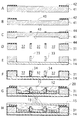
続いて、本実施形態のレンズアレイ30の製造方法について説明する。   Then, the manufacturing method of the lens array 30 of this embodiment is demonstrated.

図10は、レンズアレイ30の一製造方法を説明するための要部工程断面図である。図示の例では、多孔板31としてシリコン基板を用い、共通基板14としてパイレックスガラス(商品名)等のガラス基板を用いた例を示している。   FIG. 10 is a process cross-sectional view of a main part for explaining one manufacturing method of the lens array 30. In the illustrated example, a silicon substrate is used as the perforated plate 31, and a glass substrate such as Pyrex glass (trade name) is used as the common substrate 14.

まず、図10Aに示すように、多孔板31を構成するシリコン基板41の一方の面に、フォトリソグラフィ技術を用いて所定形状にパターニングされたレジスト層42を形成する。そして、図10Bに示すように、レジスト層42をマスクとしてシリコン基板41の一方の面を所定量エッチングする。これにより、シリコン基板41の一方の面に所定深さの凹部43が形成される。この凹部43は、レンズアレイ30において、多孔板31と共通基板14との間に形成される液連通用の通路35(図6B)を構成する。   First, as shown in FIG. 10A, a resist layer 42 patterned in a predetermined shape is formed on one surface of a silicon substrate 41 constituting the porous plate 31 by using a photolithography technique. Then, as shown in FIG. 10B, a predetermined amount of one surface of the silicon substrate 41 is etched using the resist layer 42 as a mask. As a result, a recess 43 having a predetermined depth is formed on one surface of the silicon substrate 41. The recess 43 constitutes a liquid communication passage 35 (FIG. 6B) formed between the porous plate 31 and the common substrate 14 in the lens array 30.

次に、レジスト層42を除去し、図10Cに示すように、シリコン基板41の他方の面に、フォトリソグラフィ技術を用いて所定形状にパターニングされたレジスト層44を形成する。そして、図10Dに示すように、レジスト層44をマスクとしてシリコン基板41の他方の面をエッチングし、シリコン基板41を貫通する複数の開口部32を形成する。以上のようにして、共通基板14と蓋体15との間に配置される多孔板31が作製される。   Next, the resist layer 42 is removed, and as shown in FIG. 10C, a resist layer 44 that is patterned into a predetermined shape using a photolithography technique is formed on the other surface of the silicon substrate 41. 10D, the other surface of the silicon substrate 41 is etched using the resist layer 44 as a mask to form a plurality of openings 32 penetrating the silicon substrate 41. As described above, the porous plate 31 disposed between the common substrate 14 and the lid 15 is manufactured.

続いて、レジスト層44を除去し、図10Eに示すように、多孔板31の一方の面と共通基板14の上面とを陽極接合して一体化する。その後、図10Fに示すように、多孔板31及び共通基板14の各々の表面に絶縁膜34を形成する。これにより、多孔板31の非開口部33が絶縁膜34で被覆される。   Subsequently, the resist layer 44 is removed, and as shown in FIG. 10E, the one surface of the perforated plate 31 and the upper surface of the common substrate 14 are anodically bonded and integrated. Thereafter, as shown in FIG. 10F, an insulating film 34 is formed on the surfaces of the perforated plate 31 and the common substrate 14. As a result, the non-opening 33 of the porous plate 31 is covered with the insulating film 34.

次に、図10Gに示すように、多孔板31の枠部上面に密封部材20を設けることで液室を形成するとともに、多孔板31の開口部32内に導電性の第1の液体11と絶縁性の第2の液体12を充填する。第1,第2の液体11,12の充填方法としては、シリンジあるいはディスペンサノズル等の液滴下手段を用いて各開口部32に所定量の第2の液体12を注入した後、液室を第1の液体11で充填する方法のほか、最初に第1の液体11で液室を充填した後、各開口部32に個々に第2の液体12を所定量注入する方法がある。   Next, as shown in FIG. 10G, the liquid chamber is formed by providing the sealing member 20 on the upper surface of the frame portion of the porous plate 31, and the conductive first liquid 11 is formed in the opening 32 of the porous plate 31. The insulating second liquid 12 is filled. As a filling method of the first and second liquids 11 and 12, a predetermined amount of the second liquid 12 is injected into each opening 32 using a droplet dropping means such as a syringe or a dispenser nozzle, and then the liquid chamber is changed to the first liquid chamber. In addition to the method of filling with one liquid 11, there is a method of filling a predetermined amount of the second liquid 12 into each opening 32 after first filling the liquid chamber with the first liquid 11.

最後に、図10Hに示すように、密封部材20の上に蓋体15を配置し、液室内の第1,第2の液体11,12を封止する。これにより、第1,第2の液体11,12からなるレンズ素子13が複数二次元的に配列されたレンズアレイ30が作製される。   Finally, as shown in FIG. 10H, the lid 15 is disposed on the sealing member 20, and the first and second liquids 11 and 12 in the liquid chamber are sealed. Thereby, a lens array 30 in which a plurality of lens elements 13 made of the first and second liquids 11 and 12 are two-dimensionally arranged is manufactured.

本実施形態によれば、隣接する複数のレンズ素子13間が液的に連通された構成であるので、レンズ素子13間の液量のバラツキを抑えることができる。また、素子単位で液量を高精度に調整する必要をなくすことができる。以上により、レンズアレイ30を構成する各レンズ素子13のレンズ特性を容易かつ均一化することができるとともに、レンズアレイ30の組立ても容易となる。
According to the present embodiment, since the adjacent lens elements 13 are in fluid communication with each other, variation in the liquid amount between the lens elements 13 can be suppressed. In addition, it is possible to eliminate the need to adjust the liquid amount with high accuracy in units of elements. As described above, the lens characteristics of the lens elements 13 constituting the lens array 30 can be easily and uniformized , and the lens array 30 can be easily assembled.

次に、図11〜図13を参照して、レンズアレイ30の他の製造方法を説明する。ここで、図11Aは、レンズアレイ30の構成を示す要部断面図、図11Bは図11Aにおける[B]−[B]線方向断面図、図12及び図13はレンズアレイ30の製造方法を説明する工程断面図である。   Next, another method for manufacturing the lens array 30 will be described with reference to FIGS. Here, FIG. 11A is a cross-sectional view of the main part showing the configuration of the lens array 30, FIG. 11B is a cross-sectional view in the direction [B]-[B] in FIG. 11A, and FIGS. It is process sectional drawing to demonstrate.

図11に示すレンズアレイ30は、多孔板31の枠部31Fの所定位置に、液室内へ第1,第2の液体11,12を導入するための液導入口47Aと、液室内から第1,第2の液体11,12を排出するための液排出口47Bがそれぞれ形成されているとともに、これら液導入口47A及び液排出口47Bがシール部材46A,46Bによってそれぞれ封止された構成を有している。液導入口47A及び液排出口47Bの形成位置は特に限定されないが、本例では、多孔板31の中心に関して対称な位置にそれぞれ形成されている。   The lens array 30 shown in FIG. 11 has a liquid introduction port 47A for introducing the first and second liquids 11 and 12 into the liquid chamber at a predetermined position of the frame portion 31F of the perforated plate 31, and a first from the liquid chamber. The liquid discharge ports 47B for discharging the second liquids 11 and 12 are respectively formed, and the liquid introduction port 47A and the liquid discharge port 47B are respectively sealed by the seal members 46A and 46B. is doing. The formation positions of the liquid introduction port 47 </ b> A and the liquid discharge port 47 </ b> B are not particularly limited, but in this example, they are formed at symmetrical positions with respect to the center of the porous plate 31.

また、図11に示すレンズアレイ30は、多孔板31の非開口部33と共通基板14との間に支柱38が設けられている。支柱38は図9Aに示したような構成を有しており、ここではその詳しい説明は省略する。なお、本例において支柱38は、多孔板31と一体形成されている。   In the lens array 30 shown in FIG. 11, a column 38 is provided between the non-opening 33 of the perforated plate 31 and the common substrate 14. The column 38 has a configuration as shown in FIG. 9A, and a detailed description thereof is omitted here. In this example, the support column 38 is integrally formed with the perforated plate 31.

上述した構成のレンズアレイ30の製造方法について図12及び図13を参照して説明する。まず、図12Aに示すように、多孔板31を構成するシリコン基板61の一方の面に、フォトリソグラフィ技術を用いて所定形状にパターニングされたレジスト層62を形成する。そして、図12Bに示すように、レジスト層62をマスクとしてシリコン基板61の一方の面を所定量エッチングする。これにより、シリコン基板61の一方の面に所定深さの凹部63が形成されるとともに、支柱38、液導入口47A及び液排出口47Bが形成される。なお、凹部63は、多孔板31と共通基板14との間に形成される液連通用の通路を構成する。   A method for manufacturing the lens array 30 having the above-described configuration will be described with reference to FIGS. First, as shown in FIG. 12A, a resist layer 62 patterned into a predetermined shape is formed on one surface of a silicon substrate 61 constituting the porous plate 31 by using a photolithography technique. Then, as shown in FIG. 12B, a predetermined amount of one surface of the silicon substrate 61 is etched using the resist layer 62 as a mask. As a result, a recess 63 having a predetermined depth is formed on one surface of the silicon substrate 61, and a support 38, a liquid inlet 47A, and a liquid outlet 47B are formed. The recess 63 constitutes a liquid communication passage formed between the perforated plate 31 and the common substrate 14.

次に、レジスト層62を除去し、図12Cに示すように、シリコン基板61の他方の面に、フォトリソグラフィ技術を用いて所定形状にパターニングされたレジスト層64を形成する。そして、図12Dに示すように、レジスト層64をマスクとしてシリコン基板61の他方の面をエッチングし、シリコン基板61を貫通する複数の開口部32を形成する。以上のようにして、共通基板14と蓋体15との間に配置される多孔板31が作製される。   Next, the resist layer 62 is removed, and as shown in FIG. 12C, a resist layer 64 patterned into a predetermined shape using a photolithography technique is formed on the other surface of the silicon substrate 61. Then, as shown in FIG. 12D, the other surface of the silicon substrate 61 is etched using the resist layer 64 as a mask to form a plurality of openings 32 penetrating the silicon substrate 61. As described above, the porous plate 31 disposed between the common substrate 14 and the lid 15 is manufactured.

続いて、レジスト層64を除去し、図12Eに示すように、多孔板31の枠部の上記一方の面及び支柱38の先端と共通基板14の上面とを陽極接合して一体化する。その後、図13Fに示すように、多孔板31及び共通基板14の各々の表面に絶縁膜34を形成する。これにより、多孔板31の支柱38を含む非開口部33が絶縁膜34で被覆される。   Subsequently, the resist layer 64 is removed, and as shown in FIG. 12E, the one surface of the frame portion of the perforated plate 31 and the tip of the column 38 and the upper surface of the common substrate 14 are anodically bonded and integrated. Thereafter, as shown in FIG. 13F, an insulating film 34 is formed on the surfaces of the perforated plate 31 and the common substrate 14. As a result, the non-opening 33 including the support post 38 of the porous plate 31 is covered with the insulating film 34.

次に、図13Gに示すように、多孔板31の枠部上面に密封部材20を介して蓋体15を配置することで液室を形成する。次に、図13Hに示すように、液導入口47Aから第1の液体11を導入し、多孔板31と共通基板14および蓋体15との間に形成された液連通用の通路を介して液室内に第1の液体11を充填する。このとき、液排出口47Bは開放しておき、液室内の残留空気と第1の液体11の余剰分を当該液排出口47Bから排出する。なお、図13H以降においては、液導入口47A及び液排出口47Bを断面で示す。   Next, as shown in FIG. 13G, a liquid chamber is formed by disposing the lid 15 on the upper surface of the frame portion of the perforated plate 31 via the sealing member 20. Next, as shown in FIG. 13H, the first liquid 11 is introduced from the liquid introduction port 47A, and the liquid communication passage formed between the perforated plate 31, the common substrate 14, and the lid 15 is provided. The liquid chamber is filled with the first liquid 11. At this time, the liquid discharge port 47B is kept open, and the remaining air in the liquid chamber and the excess of the first liquid 11 are discharged from the liquid discharge port 47B. In FIG. 13H and thereafter, the liquid inlet 47A and the liquid outlet 47B are shown in cross section.

次に、図13Iに示すように、液排出口47Bを開放した状態のまま、液導入口47Aから第2の液体12を導入する。第2の液体12は、多孔板31と共通基板14との間の液連通用の通路を介して液室の全域に行き渡り、撥水性の絶縁膜34によって多孔板31の開口部32周縁に濡れ広がる。第2の液体12の導入当初、液排出口47Bから第1の液体11が排出されるが、第2の液体12が液排出口47Bに達すると、第1の液体11は排出されなくなる。最後に、図13Jに示すように、液導入口47Aと液排出口47Bをシール部材46A,46Bを用いてそれぞれ封止する。   Next, as shown in FIG. 13I, the second liquid 12 is introduced from the liquid introduction port 47A while the liquid discharge port 47B is opened. The second liquid 12 spreads throughout the liquid chamber through a liquid communication path between the porous plate 31 and the common substrate 14, and is wetted around the periphery of the opening 32 of the porous plate 31 by the water-repellent insulating film 34. spread. At the beginning of the introduction of the second liquid 12, the first liquid 11 is discharged from the liquid discharge port 47B. However, when the second liquid 12 reaches the liquid discharge port 47B, the first liquid 11 is not discharged. Finally, as shown in FIG. 13J, the liquid introduction port 47A and the liquid discharge port 47B are sealed using seal members 46A and 46B, respectively.

なお、第2の液体12の濡れ広がり速度が遅い場合には、液排出口47Bに到達後も第2の液体12の導入作業を続行し、液室内における第2の液体12の液量を増やして、第1の液体11と第2の液体の界面の上昇を促すようにする。   If the wetting and spreading speed of the second liquid 12 is slow, the introduction operation of the second liquid 12 is continued even after reaching the liquid discharge port 47B, and the amount of the second liquid 12 in the liquid chamber is increased. Thus, an increase in the interface between the first liquid 11 and the second liquid is promoted.

以上のようにして、液室内に第1、第2の液体11,12からなるレンズ素子13が複数二次元的に配列されたレンズアレイ30を作製することができる。本実施形態によれば、隣接する複数のレンズ素子13間が液的に連通された構成であるので、レンズ素子13間の液量のバラツキを抑えることができる。また、素子単位で液量を高精度に調整する必要をなくすことができる。以上により、レンズアレイ30を構成する各レンズ素子13のレンズ特性を均一化することができるとともに、レンズアレイ30の組立ても容易となる。   As described above, it is possible to manufacture the lens array 30 in which a plurality of lens elements 13 made of the first and second liquids 11 and 12 are two-dimensionally arranged in the liquid chamber. According to the present embodiment, since the adjacent lens elements 13 are in fluid communication with each other, variation in the liquid amount between the lens elements 13 can be suppressed. In addition, it is possible to eliminate the need to adjust the liquid amount with high accuracy in units of elements. As described above, the lens characteristics of the lens elements 13 constituting the lens array 30 can be made uniform, and the lens array 30 can be easily assembled.

本実施形態によれば、液室の側方から第1,第2の液体11,12を順に導入することでレンズアレイ30を作製するようにしているので、第2の液体12を液量調整して個々に滴下注入する作業が不要となり、レンズアレイ30の組立て作業を更に容易に行うことができる。更に、シリンジやディスペンサノズル等を用いる方法では液体充填できないような微小なレンズ径(例えば数μm〜数十μm)をもつ構造にも容易に対応することができるようになる。   According to this embodiment, since the lens array 30 is produced by sequentially introducing the first and second liquids 11 and 12 from the side of the liquid chamber, the liquid amount of the second liquid 12 is adjusted. Thus, the operation of dropping and injecting individually becomes unnecessary, and the assembly operation of the lens array 30 can be performed more easily. Furthermore, it becomes possible to easily cope with a structure having a minute lens diameter (for example, several μm to several tens μm) that cannot be filled with liquid by a method using a syringe, a dispenser nozzle, or the like.

また、本実施形態によれば、第1,第2の液体11,12の導入圧を適宜調整することが可能である。例えば、液室内を大気圧よりも大きな圧力状態に保つことで、外部環境(例えば高山での減圧、水中での加圧)などの影響を受けにくいデバイスを構成することができる。   Further, according to the present embodiment, the introduction pressures of the first and second liquids 11 and 12 can be adjusted as appropriate. For example, by maintaining the pressure in the liquid chamber at a pressure greater than atmospheric pressure, a device that is less susceptible to the influence of the external environment (for example, decompression in high mountains, pressurization in water) can be configured.

また、シール部材46A,46Bとしては、ゴム栓のような弾性体を液導入口47A,液排出口47Bに圧入した後、接着剤で外側を接着硬化させたり、液導入口47A,液排出口47Bに直接接着剤を注入して硬化させたりする方法がある。また、シール部材46A,46Bを、液流れ方向を規制したチェック弁(逆止弁)で構成するようにしてもよい。   Further, as the sealing members 46A and 46B, an elastic body such as a rubber plug is press-fitted into the liquid introduction port 47A and the liquid discharge port 47B, and then the outside is bonded and cured with an adhesive, or the liquid introduction port 47A and the liquid discharge port. There is a method in which an adhesive is directly injected into 47B and cured. Further, the sealing members 46A and 46B may be configured by check valves (check valves) that regulate the liquid flow direction.

本発明の第1の実施形態によるレンズアレイの概略構成図であり、Aは共通基板の平面図、Bはレンズアレイの要部断面図である。BRIEF DESCRIPTION OF THE DRAWINGS FIG. 1 is a schematic configuration diagram of a lens array according to a first embodiment of the present invention, in which A is a plan view of a common substrate and B is a cross-sectional view of a main part of the lens array. 図1のレンズアレイにおいて各レンズ素子を区画する突起の形成間隔を説明する断面図である。It is sectional drawing explaining the formation space | interval of the processus | protrusion which partitions each lens element in the lens array of FIG. 水と空気、水と油の組合せ例における界面張力、密度差、毛管長の大きさを比較して説明する図である。It is a figure which compares and demonstrates the magnitude | size of the interfacial tension, the density difference, and capillary length in the combination example of water and air and water and oil. 図1のレンズアレイにおいて各レンズ素子を区画する突起の形状の相違によるレンズ面の初期形状を説明する断面図である。It is sectional drawing explaining the initial shape of the lens surface by the difference in the shape of the processus | protrusion which partitions each lens element in the lens array of FIG. 本発明の第2の実施形態によるレンズアレイの構成を説明する共通基板の平面図である。It is a top view of the common board | substrate explaining the structure of the lens array by the 2nd Embodiment of this invention. 本発明の第3の実施形態によるレンズアレイの概略構成図であり、Aはレンズアレイの内部構造を示す平面図、Bはレンズアレイの要部断面図である。FIG. 4 is a schematic configuration diagram of a lens array according to a third embodiment of the present invention, in which A is a plan view showing an internal structure of the lens array, and B is a cross-sectional view of a main part of the lens array. 本発明の第3の実施形態によるレンズアレイの構成の変形例を示す多孔板の平面図である。It is a top view of the perforated plate which shows the modification of the structure of the lens array by the 3rd Embodiment of this invention. 図7Bに示した構成の多孔板を有するレンズアレイの要部断面図である。It is principal part sectional drawing of the lens array which has a perforated plate of the structure shown to FIG. 7B. 本発明の第3の実施形態によるレンズアレイの構成の他の変形例を示す多孔板の断面図である。It is sectional drawing of the perforated plate which shows the other modification of the structure of the lens array by the 3rd Embodiment of this invention. 本発明の第3の実施形態のレンズアレイの製造方法を説明する要部の工程断面図である。It is process sectional drawing of the principal part explaining the manufacturing method of the lens array of the 3rd Embodiment of this invention. 本発明の第3の実施形態のレンズアレイの構成の変形例を示す図であり、Aはレンズアレイの要部断面図、Bは図11Aにおける[B]−[B]線方向断面図である。It is a figure which shows the modification of the structure of the lens array of the 3rd Embodiment of this invention, A is principal part sectional drawing of a lens array, B is a [B]-[B] line direction sectional drawing in FIG. 11A. . 図11に示したレンズアレイの製造方法を説明する要部の工程断面図である。It is process sectional drawing of the principal part explaining the manufacturing method of the lens array shown in FIG. 図11に示したレンズアレイの製造方法を説明する要部の工程断面図である。It is process sectional drawing of the principal part explaining the manufacturing method of the lens array shown in FIG. 電気毛管現象を説明する原理図である。It is a principle figure explaining an electrocapillary phenomenon. 従来のレンズアレイの概略構成図であり、Aは共通基板の平面図、Bはレンズアレイの要部断面図である。It is a schematic block diagram of the conventional lens array, A is a top view of a common substrate, B is principal part sectional drawing of a lens array.

符号の説明Explanation of symbols

10,30…レンズアレイ、11…第1の液体、12…第2の液体、13…レンズ素子、13A…界面(レンズ面)、14…共通基板、15…蓋体、16…突起(柱状突起)、17,18,37…透明電極、19,34…絶縁膜、20…密封部材、26…突起(線状突起)、27,35,36…通路、31…多孔板、32…開口部、33…非開口部、38…支柱、46A,46B…シール部材、47A…液導入口、47B…液排出口   DESCRIPTION OF SYMBOLS 10,30 ... Lens array, 11 ... 1st liquid, 12 ... 2nd liquid, 13 ... Lens element, 13A ... Interface (lens surface), 14 ... Common substrate, 15 ... Cover, 16 ... Protrusion (columnar protrusion) , 17, 18, 37 ... transparent electrode, 19, 34 ... insulating film, 20 ... sealing member, 26 ... projection (linear projection), 27, 35, 36 ... passage, 31 ... perforated plate, 32 ... opening, 33 ... Non-opening part, 38 ... Post, 46A, 46B ... Seal member, 47A ... Liquid inlet, 47B ... Liquid outlet

Claims (3)

導電性の第1の液体と、
前記第1の液体と屈折率が異なる絶縁性の第2の液体と、
前記第1、第2の液体の界面でレンズ面を形成する複数のレンズ素子であって、共通基板と、前記共通基板に対向する蓋体との間に形成された液室内において、前記共通基板上に立設された柱状突起を四隅として区画され、二次元的に配列された複数のレンズ素子と
を具備するレンズアレイ。
A conductive first liquid;
An insulating second liquid having a refractive index different from that of the first liquid;
A plurality of lens elements forming a lens surface at an interface between the first and second liquids , wherein the common substrate is formed in a liquid chamber formed between a common substrate and a lid body facing the common substrate. A plurality of lens elements, which are partitioned in two corners, with columnar protrusions standing upright as four corners, and
A lens array.
導電性の第1の液体と、
前記第1の液体と屈折率が異なる絶縁性の第2の液体と、
前記第1、第2の液体の界面でレンズ面を形成する複数のレンズ素子であって、共通基板と、前記共通基板に対向する蓋体との間に形成された液室内において、前記共通基板上に立設された液連通を許容する通路が形成された線状突起で区画され、二次元的に配列された複数のレンズ素子と
を具備するレンズアレイ。
A conductive first liquid;
An insulating second liquid having a refractive index different from that of the first liquid;
A plurality of lens elements forming a lens surface at an interface between the first and second liquids , wherein the common substrate is formed in a liquid chamber formed between a common substrate and a lid body facing the common substrate. A plurality of lens elements arranged in a two-dimensional manner, partitioned by linear protrusions formed with passages allowing liquid communication standing on the top ;
A lens array.
請求項1又は2に記載のレンズアレイであって、
前記共通基板と前記蓋体の間には、前記液室の外部から内部へ前記第1、第2の液体を導入する液導入口と、前記液室の内部から外部へ前記第1、第2の液体を排出する液排出口が設けられている
レンズアレイ。
The lens array according to claim 1 or 2,
Between the common substrate and the lid, a liquid inlet for introducing the first and second liquids from the outside to the inside of the liquid chamber, and the first and second from the inside of the liquid chamber to the outside. A lens array that is provided with a liquid outlet for discharging liquid.
JP2006341595A 2006-07-10 2006-12-19 Lens array Expired - Fee Related JP4984875B2 (en)

Priority Applications (2)

Application Number Priority Date Filing Date Title
JP2006341595A JP4984875B2 (en) 2006-07-10 2006-12-19 Lens array
US12/306,909 US7952809B2 (en) 2006-07-10 2007-07-10 Lens array

Applications Claiming Priority (3)

Application Number Priority Date Filing Date Title
JP2006188781 2006-07-10
JP2006341595A JP4984875B2 (en) 2006-07-10 2006-12-19 Lens array

Publications (3)

Publication Number Publication Date
JP2008040455A JP2008040455A (en) 2008-02-21
JP2008040455A5 JP2008040455A5 (en) 2010-02-12
JP4984875B2 true JP4984875B2 (en) 2012-07-25

Family

ID=39175466

Family Applications (1)

Application Number Title Priority Date Filing Date
JP2006341595A Expired - Fee Related JP4984875B2 (en) 2006-07-10 2006-12-19 Lens array

Country Status (1)

Country Link
JP (1) JP4984875B2 (en)

Cited By (1)

* Cited by examiner, † Cited by third party
Publication number Priority date Publication date Assignee Title
US9733484B2 (en) 2014-04-29 2017-08-15 Samsung Display Co., Ltd. Image display apparatus

Families Citing this family (6)

* Cited by examiner, † Cited by third party
Publication number Priority date Publication date Assignee Title
JP2009251339A (en) * 2008-04-08 2009-10-29 Sony Corp Optical device, illuminator, and camera
JP5256843B2 (en) * 2008-05-13 2013-08-07 ソニー株式会社 Optical element and manufacturing method thereof
FR2962557B1 (en) * 2010-07-12 2013-06-07 Commissariat Energie Atomique METHOD FOR MANUFACTURING A MEMBRANE DEVICE IMPRINTING A FLUID
JP5685891B2 (en) * 2010-11-02 2015-03-18 ソニー株式会社 Optical element and stereoscopic display device
JP2012181513A (en) * 2011-02-10 2012-09-20 Daikin Ind Ltd Hydrophobic dielectric film for electrowetting
TWI467228B (en) * 2012-11-30 2015-01-01 Nat Univ Chung Hsing An electric wetting element and its making method

Family Cites Families (7)

* Cited by examiner, † Cited by third party
Publication number Priority date Publication date Assignee Title
US5731792A (en) * 1996-05-06 1998-03-24 Xerox Corporation Electrocapillary color display sheet
JP2000356708A (en) * 1999-06-16 2000-12-26 Canon Inc Photodiffusion element and stroboscopic device utilizing the same
JP2000356750A (en) * 1999-06-16 2000-12-26 Canon Inc Display element and display device
JP2002162507A (en) * 2000-11-27 2002-06-07 Canon Inc Optical element, illuminator and photographing device
JP2002169110A (en) * 2000-11-30 2002-06-14 Canon Inc Optical element, optical device and photographing device
DE60330685D1 (en) * 2002-09-19 2010-02-04 Koninkl Philips Electronics Nv OPTICAL SWITCH BASED ON ELECTROCONDUCTION
US6847493B1 (en) * 2003-08-08 2005-01-25 Lucent Technologies Inc. Optical beamsplitter with electro-wetting actuation

Cited By (1)

* Cited by examiner, † Cited by third party
Publication number Priority date Publication date Assignee Title
US9733484B2 (en) 2014-04-29 2017-08-15 Samsung Display Co., Ltd. Image display apparatus

Also Published As

Publication number Publication date
JP2008040455A (en) 2008-02-21

Similar Documents

Publication Publication Date Title
KR101426970B1 (en) Lens array
JP4984875B2 (en) Lens array
JP4760426B2 (en) Optical element and lens array
US7898742B2 (en) Variable focus microlens
JP4332176B2 (en) Variable focus lens with multiple projections formed at one end of fluid chamber
CN107690597B (en) Optical device with variable aperture
JP2007225779A (en) Optical element and method of manufacturing same
KR100674866B1 (en) Variable-focus lens and fabrication method thereof
JP2009518676A (en) Prevention of solution flow in a fluid focus lens.
JP4862659B2 (en) Manufacturing method of electrowetting device
JP2006243169A (en) Image display device
JP5382944B2 (en) Variable focus lens and liquid filling method thereof
KR100797676B1 (en) Liquid-lens module
KR20080035252A (en) Liquid lens making focal point in 3-dimensional space
US8031408B2 (en) Fluid displacement mechanism
WO2019226733A1 (en) Electrowetting devices
JP2005316321A (en) Display device
KR20060129780A (en) Optical instrument
JP2012048244A (en) Variable focus microlens

Legal Events

Date Code Title Description
A521 Written amendment

Free format text: JAPANESE INTERMEDIATE CODE: A523

Effective date: 20091217

A621 Written request for application examination

Free format text: JAPANESE INTERMEDIATE CODE: A621

Effective date: 20091217

A131 Notification of reasons for refusal

Free format text: JAPANESE INTERMEDIATE CODE: A131

Effective date: 20120117

A521 Written amendment

Free format text: JAPANESE INTERMEDIATE CODE: A523

Effective date: 20120309

TRDD Decision of grant or rejection written
A01 Written decision to grant a patent or to grant a registration (utility model)

Free format text: JAPANESE INTERMEDIATE CODE: A01

Effective date: 20120403

A01 Written decision to grant a patent or to grant a registration (utility model)

Free format text: JAPANESE INTERMEDIATE CODE: A01

A61 First payment of annual fees (during grant procedure)

Free format text: JAPANESE INTERMEDIATE CODE: A61

Effective date: 20120416

FPAY Renewal fee payment (event date is renewal date of database)

Free format text: PAYMENT UNTIL: 20150511

Year of fee payment: 3

LAPS Cancellation because of no payment of annual fees