JP4984790B2 - Vehicle fuel meter control device - Google Patents
Vehicle fuel meter control device Download PDFInfo
- Publication number
- JP4984790B2 JP4984790B2 JP2006262228A JP2006262228A JP4984790B2 JP 4984790 B2 JP4984790 B2 JP 4984790B2 JP 2006262228 A JP2006262228 A JP 2006262228A JP 2006262228 A JP2006262228 A JP 2006262228A JP 4984790 B2 JP4984790 B2 JP 4984790B2
- Authority
- JP
- Japan
- Prior art keywords
- fuel
- amount
- display
- remaining amount
- value
- Prior art date
- Legal status (The legal status is an assumption and is not a legal conclusion. Google has not performed a legal analysis and makes no representation as to the accuracy of the status listed.)
- Expired - Fee Related
Links
Images


Description
この発明は、車両のフューエルメータ制御装置に関し、特に、車両の走行状態の如何に関わらずフューエルメータの表示を正確におこなうことができる車両のフューエルメータ制御装置に関する。 The present invention relates to a fuel meter control device for a vehicle, and more particularly to a fuel meter control device for a vehicle that can accurately display the fuel meter regardless of the traveling state of the vehicle.
従来より、車両においては、燃料タンク内の燃料残量をドライバーに認識させるため、運転席の計器類の中に、燃料残量表示計、いわゆるフューエルメータを設けている。 Conventionally, in a vehicle, in order to make the driver recognize the remaining amount of fuel in the fuel tank, a remaining fuel indicator, a so-called fuel meter, is provided in the instrumentation of the driver's seat.
このフューエルメータは、燃料タンク内に設けたフロートセンサで燃料タンク内の燃料残量を検出し、この検出信号を制御装置内に取り込んだ後、制御装置内で表示処理された表示信号によって、所定の残量値を針等により表示するように構成されている。 This fuel meter detects the remaining amount of fuel in the fuel tank with a float sensor provided in the fuel tank, takes this detection signal into the control device, and then uses the display signal displayed in the control device to perform a predetermined process. The remaining amount value is displayed with a needle or the like.
このフューエルメータでは、フロート(浮き)を使ったフロートセンサで燃料タンク内の燃料の液面位置を検出しているため、車両の走行状態(走行時の加減速度、路面勾配等)により、実際の残量よりも多く又は少なく残量を検出するおそれがある。 In this fuel meter, the liquid level position of the fuel in the fuel tank is detected by a float sensor that uses a float (float). Therefore, depending on the vehicle's running condition (acceleration / deceleration, road gradient, etc.) There is a risk of detecting the remaining amount more or less than the remaining amount.
このため、例えば、下記特許文献1に示すように、フューエルメータの表示速度を遅らせる等して、こうした表示誤差を少なくするように構成したフューエルメータ制御装置が知られている。
ところで、車両は、様々な走行状態に応じて前後左右方向Gを受ける。これに伴い、燃料タンク内の燃料もタンク内で前後左右に揺動することになる。
このため、燃料の液面位置も大きく上下に揺動することになり、フロートセンサのフロートも上下方向に大きく移動することになる。
By the way, the vehicle receives the front-rear and left-right directions G according to various traveling states. Accordingly, the fuel in the fuel tank also swings back and forth and left and right in the tank.
For this reason, the liquid level of the fuel also largely fluctuates up and down, and the float of the float sensor also moves greatly in the vertical direction.
このとき、フューエルメータ制御装置では、所定回数検出した検出値の平均値等から、燃料タンク内の燃料残量の真値を推定して、フューエルメータの表示量を算出しているが、燃料残量と走行状態によっては、フロートセンサの検出値に所定の傾向が生じるため、定常走行時の値と加減速走行時の値との間にズレが生じる場合がある。 At this time, the fuel meter control device calculates the fuel meter display amount by estimating the true value of the fuel remaining amount in the fuel tank from the average value of the detected values detected a predetermined number of times. Depending on the amount and the running state, a predetermined tendency occurs in the detection value of the float sensor, and thus there may be a deviation between the value during steady running and the value during acceleration / deceleration running.
図6の模式図は、その所定の傾向を説明するための模式図である。この模式図は、ほぼ真四角の立方体形状の燃料タンクにおいて、フロートセンサを略中央位置に設置した場合における、フロートの上下動を表したものであり、上段が燃料残量が燃料タンク容量の約1/2より多い場合の模式図、下段が燃料残量が燃料タンク容量の約1/2より少ない場合の模式図である。 The schematic diagram of FIG. 6 is a schematic diagram for explaining the predetermined tendency. This schematic diagram shows the vertical movement of the float when the float sensor is installed at a substantially central position in a substantially square cubic fuel tank. A schematic diagram in the case of more than 1/2, and a lower diagram is a schematic diagram in a case where the remaining amount of fuel is less than about 1/2 of the fuel tank capacity.
燃料残量が約1/2より多い場合、すなわち、燃料がタンク内エアよりも多い場合では、燃料タンクが前後方向に大きく揺動すると、エアが燃料タンクの前後位置に移動することになり、結果的に中央の液面位置が定常状態の位置より上方に上がってしまい、フロートが上方に移動してしまう。 When the remaining amount of fuel is more than about 1/2, that is, when the fuel is larger than the air in the tank, if the fuel tank swings greatly in the front-rear direction, the air moves to the front-rear position of the fuel tank, As a result, the central liquid surface position rises upward from the steady state position, and the float moves upward.
これに対して、燃料残量が約1/2より多い場合、すなわち、燃料がタンク内エアよりも少ない場合では、燃料タンクが前後方向に大きく揺動すると、逆に燃料が燃料タンクの前後位置に移動することになり、中央の液面位置が定常状態の位置より下方に下がってしまい、フロートが下方に移動してしまう。 On the other hand, when the remaining amount of fuel is more than about 1/2, that is, when the fuel is less than the air in the tank, if the fuel tank swings greatly in the front-rear direction, the fuel is conversely moved back and forth in the fuel tank. As a result, the center liquid level position falls below the steady state position, and the float moves downward.
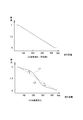
こうしたフロートの傾向から、図7の燃料表示特性図に示すように、(b)に示す加減速走行時には、燃料残量が多い状態で(a)に示す定常走行時の値より表示値が多く表示されることになり、燃料残量が少ない状態で(a)に示す定常走行時の値よりも表示値が少なく表示されるといったズレが生じるのである。 From the tendency of the float, as shown in the fuel display characteristic diagram of FIG. 7, during acceleration / deceleration running shown in (b), the display value is larger than the value during steady running shown in (a) with a large amount of remaining fuel. This results in a deviation in that the display value is displayed less than the value during steady running shown in (a) when the remaining amount of fuel is low.
このズレに対しては、前述の特許文献1のように表示速度を低くしたとしても、基礎とする検出値自体が、真値と大きなズレがあるため、フューエルメータで正確な残量表示を行なうことができず、十分には対策することができない。
For this deviation, even if the display speed is lowered as in the above-mentioned
そこで、本発明は、車両のフューエルメータ制御装置において、走行状態によって変動する燃料タンクの燃料残量の表示量を、できるだけ定常走行時の値に近づけて、より正確な燃料残量を表示することができるフューエルメータ制御装置を提供することを目的とする。 In view of this, the present invention provides a fuel meter control device for a vehicle that displays the remaining amount of fuel in the fuel tank, which fluctuates depending on the traveling state, as close as possible to the value during steady traveling, and displays a more accurate remaining fuel amount. An object of the present invention is to provide a fuel meter control device capable of performing
この発明の車両のフューエルメータ制御装置は、燃料タンク内の燃料残量を検出する燃料残量検出手段と、該燃料残量検出手段の検出信号を受けて当該検出信号の変化に基いて燃料残量を表示する燃料残量表示手段とを備えた車両のフューエルメータ制御装置において、燃料残量の検出信号と車両の走行状態の検出信号とに基いて、前記燃料残量検出手段から求められる燃料残量表示手段の表示量を補正する補正手段を備え、前記燃料タンク内の燃料残量が、燃料タンク半分近傍の所定値より多い状態では、燃料残量検出手段の検出信号から求められる燃料残量表示手段の表示量を減少補正するものである。 A fuel meter control device for a vehicle according to the present invention comprises a fuel remaining amount detecting means for detecting a remaining amount of fuel in a fuel tank, and a fuel remaining amount detecting means based on a change in the detected signal upon receiving a detection signal from the remaining fuel amount detecting means. In a fuel meter control device for a vehicle comprising a fuel remaining amount display means for displaying the amount of fuel, the fuel obtained from the fuel remaining amount detecting means based on a detection signal for the remaining amount of fuel and a detection signal for the running state of the vehicle Correction means for correcting the display amount of the remaining amount display means, and in a state where the remaining amount of fuel in the fuel tank is greater than a predetermined value near the half of the fuel tank, the remaining fuel amount obtained from the detection signal of the remaining fuel amount detecting means The display amount of the amount display means is corrected to decrease .
上記構成によれば、補正手段によって、燃料残量と車両の走行状態に基いて燃料残量表示手段の表示量が補正されることになる。
このため、車両の走行状態に応じて変化する検出値と定常走行時の検出値とのズレ量を、補正によって少なくすることができ、より定常走行時の値に近い値を表示することができる。
また、上記構成によれば、燃料タンク内の燃料残量が多い時には、表示量が減少補正されることになる。
このため、燃料残量が多い場合に、車両の走行状態によって燃料残量の検出値が定常走行時の値よりも上昇しても、表示量を定常走行時の値により近い値にすることができる。
よって、車両の走行状態に関わらず、定常走行時の値により近い値で、燃料残量表示手段の表示を行なうことができる。
According to the above configuration, the display amount of the remaining fuel amount display unit is corrected by the correcting unit based on the remaining fuel amount and the running state of the vehicle.
For this reason, the amount of deviation between the detected value that changes in accordance with the running state of the vehicle and the detected value during steady running can be reduced by correction, and a value closer to the value during steady running can be displayed. .
Further, according to the above configuration, when the remaining amount of fuel in the fuel tank is large, the display amount is corrected to decrease.
For this reason, when the remaining amount of fuel is large, even if the detected value of the remaining amount of fuel rises above the value at the time of steady running due to the running state of the vehicle, the display amount can be made closer to the value at the time of steady running. it can.
Therefore, regardless of the running state of the vehicle, the fuel remaining amount display means can be displayed with a value closer to the value during steady running.
なお、燃料残量表示手段であるフューエルメータは、針表示のアナログタイプであってもよいし、液晶表示のデジタルタイプであってもよい。
また、車両の走行状態は、横Gセンサ、前後Gセンサ、勾配センサ等で検出してもよいし、舵角センサ、ペダルセンサ等による操作系のセンサから検出してもよい。
The fuel meter that is the fuel remaining amount display means may be an analog type with a needle display or a digital type with a liquid crystal display.
Further, the traveling state of the vehicle may be detected by a lateral G sensor, a front-rear G sensor, a gradient sensor, or the like, or may be detected by an operation system sensor such as a steering angle sensor or a pedal sensor.
この発明の一実施態様においては、前記燃料残量検出手段の検出信号に含まれる検出値の所定回数ごとの平均を算出し、又は一定期間ごとの検出値の平均を連続的に算出する移動平均の平均化処理によって、燃料残量を算出するものであり、前記検出値の検出回ごとの変化に基いて、前記車両の走行状態を検出するものである。
上記構成によれば、車両の走行状態を、燃料タンク内の液面の変動によって検出することになる。
このため、前後Gセンサや横Gセンサ等を新たに設けることなく、燃料残量検出手段の検出信号の振幅を検出するだけで、フューエルメータの補正制御を行なうことができる。
よって、燃料残量検出手段に、走行状態を検出する検出手段としての機能も兼ねさせることで、コストを掛けることなく、燃料残量検出手段の検出値のズレ量を補正することができる。
In one embodiment of the present invention, a moving average that calculates an average of detection values included in a detection signal of the fuel remaining amount detection means every predetermined number of times, or continuously calculates an average of detection values every predetermined period. In this averaging process, the remaining fuel amount is calculated, and the running state of the vehicle is detected based on the change of the detection value for each detection time .
According to the above configuration, the traveling state of the vehicle is detected by the fluctuation of the liquid level in the fuel tank.
For this reason, it is possible to perform correction control of the fuel meter only by detecting the amplitude of the detection signal of the remaining fuel amount detection means without newly providing a front-rear G sensor or a lateral G sensor.
Therefore, by making the fuel remaining amount detecting means also function as a detecting means for detecting the running state, it is possible to correct the deviation amount of the detection value of the fuel remaining amount detecting means without incurring costs.
この発明の一実施態様においては、前記燃料タンク内の燃料残量が、燃料タンク半分近傍の所定値より少ない状態では、燃料残量検出手段の検出信号から求められる燃料残量表示手段の表示量を増大補正するものである。
上記構成によれば、燃料タンク内の燃料残量が少ない時には、表示量が増大補正されることになる。
このため、燃料残量が少ない場合に、車両の走行状態によって燃料残量の検出値が定常走行時の値よりも降下しても、表示量を定常走行時の値により近い値にすることができる。
よって、車両の走行状態に関わらず、定常走行時の値に近い値で燃料残量表示手段の表示を行なうことができる。
In one embodiment of the present invention, when the remaining amount of fuel in the fuel tank is less than a predetermined value in the vicinity of the half of the fuel tank, the display amount of the remaining fuel amount display means obtained from the detection signal of the remaining fuel amount detection means Is corrected to increase.
According to the above configuration, when the remaining amount of fuel in the fuel tank is small, the display amount is corrected to increase.
For this reason, when the remaining amount of fuel is low, even if the detected value of the remaining amount of fuel falls below the value at the time of steady running due to the running state of the vehicle, the display amount can be made closer to the value at the time of steady running. it can.
Therefore, regardless of the traveling state of the vehicle, the fuel remaining amount display means can be displayed with a value close to the value during steady traveling.
なお、これらの補正方向については、個々の燃料タンクの形状等に応じて変更するようにしてもよい。 Note that these correction directions may be changed according to the shape of each fuel tank.
この発明の一実施態様においては、車両の走行状態の変動が大きい場合には、変動が小さい場合よりも燃料残量検出手段の検出信号から求められる燃料残量表示手段の表示量の補正量を大きく設定したものである。 In one embodiment of the present invention, when the fluctuation of the running state of the vehicle is large, the correction amount of the display amount of the fuel remaining amount display means obtained from the detection signal of the fuel remaining amount detecting means is larger than when the fluctuation is small. It is a large setting.
上記構成によれば、車両の走行状態の変動量に応じて、燃料残量表示手段の表示量の補正量が変化することになる。
このため、走行状態の変動量に応じて変化する検出値と定常走行時の値との間のズレ量を、補正量を変化させることによって、確実に少なくすることができる。
よって、より定常走行時の値に近い値で、燃料残量表示手段の表示を行なうことができる。
なお、車両の走行状態を燃料残量検出手段の検出信号の振幅によって検出する場合には、振幅の振幅長さや振幅頻度等によって変動量を検出することになる。
According to the above configuration, the correction amount of the display amount of the remaining fuel amount display means changes according to the fluctuation amount of the running state of the vehicle.
For this reason, the amount of deviation between the detected value that changes in accordance with the amount of change in the running state and the value during steady running can be reliably reduced by changing the correction amount.
Therefore, the fuel remaining amount display means can be displayed with a value closer to the value during steady running.
In the case where the running state of the vehicle is detected by the amplitude of the detection signal of the fuel remaining amount detecting means, the amount of variation is detected by the amplitude length or amplitude frequency of the amplitude.
この発明の一実施態様においては、前記燃料残量表示手段における表示速度を低速化する表示速度変更手段を備えたものである。
上記構成によれば、表示速度変更手段で表示速度が低速化されることで、フューエルメータの針等が徐々に表示目標値に移動することになる。
このため、フューエルメータの針等の急激な変動が抑制され、ドライバーに違和感を与えることをなくすことができる。
よって、フューエルメータ表示の外乱の影響を少なくして、表示値の精度の向上を図ることができる。
In one embodiment of the present invention, there is provided display speed changing means for reducing the display speed of the remaining fuel amount display means.
According to the above configuration, the display speed is reduced by the display speed changing means, so that the fuel meter needle and the like gradually move to the display target value.
For this reason, rapid fluctuations in the fuel meter needle and the like can be suppressed, and the driver can be prevented from feeling uncomfortable.
Therefore, the influence of disturbance on the fuel meter display can be reduced and the accuracy of the display value can be improved.
この発明の一実施態様においては、燃料消費量を検出する燃料消費量検出手段を備え、前記表示速度変更手段が、該燃料消費量検出手段からの検出信号に基いて、燃料消費量が少ない時は、多い時に対して表示速度を低速化するように構成したものである。
上記構成によれば、燃料消費量が少ない時には表示速度が低速化されて、燃料消費量が多い時には高速化されるため、フューエルメータの針等は、燃料消費量が少ない時に燃料タンクの液面の変動の影響を受け難くなり、燃料消費量が多い時には燃料タンクの液面の変動をより正確に反映することになる。
よって、燃料消費量が少ない場合には、フューエルメータの針等の変動を抑えてドライバーに違和感を与えることをなくし、また、燃料消費量が多い場合には、ドライバーに燃料残量が減少していることを早期に認識させて、ガス欠の虞を回避することができる。
In one embodiment of the present invention, the fuel consumption amount detecting means for detecting the fuel consumption amount is provided, and the display speed changing means is based on a detection signal from the fuel consumption amount detecting means when the fuel consumption amount is small. Is configured to reduce the display speed when there are many.
According to the above configuration, when the fuel consumption is low, the display speed is reduced, and when the fuel consumption is high, the display speed is increased. Therefore, when the fuel consumption is large, the change in the liquid level of the fuel tank is more accurately reflected.
Therefore, when the fuel consumption is small, the fluctuation of the needle of the fuel meter is suppressed so that the driver does not feel uncomfortable. When the fuel consumption is large, the remaining amount of fuel is reduced for the driver. Can be recognized at an early stage, and the risk of running out of gas can be avoided.
この発明によれば、車両の走行状態に応じて変化する検出値と定常走行時の検出値とのズレ量を、補正によって少なくすることができ、より定常走行時の値に近い値を表示することができる。
よって、車両のフューエルメータ制御装置において、走行状態によって変動する燃料タンクの燃料残量の表示量を、できるだけ定常走行時の値に近づけて、より正確な燃料残量を表示することができる。
また、燃料タンク内の燃料残量が多い時には、表示量が減少補正されることになる。
このため、燃料残量が多い場合に、車両の走行状態によって燃料残量の検出値が定常走行時の値よりも上昇しても、表示量を定常走行時の値により近い値にすることができる。
よって、車両の走行状態に関わらず、定常走行時の値により近い値で、燃料残量表示手段の表示を行なうことができる。
According to the present invention, the amount of deviation between the detected value that changes according to the running state of the vehicle and the detected value during steady running can be reduced by correction, and a value closer to the value during steady running is displayed. be able to.
Therefore, in the fuel meter control device of the vehicle, the display amount of the fuel remaining amount of the fuel tank that varies depending on the traveling state can be displayed as close as possible to the value at the time of steady traveling, thereby displaying the more accurate fuel remaining amount.
Further, when the remaining amount of fuel in the fuel tank is large, the display amount is corrected to decrease.
For this reason, when the remaining amount of fuel is large, even if the detected value of the remaining amount of fuel rises above the value at the time of steady running due to the running state of the vehicle, the display amount can be made closer to the value at the time of steady running. it can.
Therefore, regardless of the running state of the vehicle, the fuel remaining amount display means can be displayed with a value closer to the value during steady running.
本発明の実施形態について、以下、図面に基づいて詳述する。
図1は第一実施形態の車両のフューエルメータ制御装置に関するシステムブロック図である。
フューエルメータ制御装置1は、燃料タンクT(図2参照)内に設置されるフロートセンサ2と、フロートセンサ2からの検出信号を受けて、表示信号を算出するフューエルメータ制御ユニット3と、運転席の計器内に設置され、フューエルメータ制御ユニット3からの表示信号を受けて、燃料残量を表示するフューエルメータ本体4とを備えている。
Hereinafter, embodiments of the present invention will be described in detail with reference to the drawings.
FIG. 1 is a system block diagram relating to a fuel meter control device for a vehicle according to a first embodiment.
The fuel
また、その他に、4つの車輪速センサ5a、5b、5c、5dと、その車輪速センサ5a、5b、5c、5dからの検出信号を受けて車速を算出する車速検出ユニット6と、さらに、エンジン(図示せず)に吸入される空気量を検出するエアフローセンサ7と、エンジンの回転数を検出するエンジン回転数センサ8と、車速信号、エアフローセンサ及びエンジン回転数センサ等の検出信号を受けて燃料噴射量等を算出するエンジン制御ユニット9と、その算出された燃料噴射量によって実際にエンジンに燃料噴射を行なう燃料噴射弁10とを備えている。
In addition, four
前述の車速検出ユニット6では、車輪速センサ5a、5b、5c、5dから4つの車輪の車輪速を検出し、この検出した車輪速から車速(車体速度)を算出している。例えば、4つの検出信号のうち、最大値を除く、3つの値の平均値から車速(車体速度)を算出している。
In the vehicle
前述のエンジン制御ユニット9では、エアフローセンサ7、エンジン回転数センサ8等のエンジン状態を検出するセンサの検出信号に基いて燃料噴射量を算出している。
In the engine control unit 9 described above, the fuel injection amount is calculated based on detection signals from sensors that detect engine conditions such as the
前述のフューエルメータ制御ユニット3には、前述のフロートセンサ2の検出信号の他に、エンジン制御ユニット9から車速と燃料噴射量が入力されるように構成している。
In addition to the detection signal of the
このフューエルメータ制御ユニット3では、フロートセンサ2の検出信号を取り込んで、目標値算定処理や時定数処理(表示速度処理)を行った上で、フューエルメータ本体4に表示信号として出力している。
The fuel
ここで、時定数処理とは、車両の走行状態等によって変動する燃料タンクTの液面位置(液位)を、外乱の影響を除いて正確に表示するために、フューエルメータ本体4の針を、直接燃料残量値(目標値)に変化させるのではなく、徐々に燃料残量値(目標値)に近づくように表示速度をおくらせる制御(いわゆる「なまし制御」)を行うことをいう。 Here, the time constant process means that the liquid level position (liquid level) of the fuel tank T, which fluctuates depending on the traveling state of the vehicle, etc., is displayed accurately without the influence of disturbance. , Instead of directly changing to the remaining fuel value (target value), performing control (so-called “smoothing control”) for gradually increasing the display speed so as to gradually approach the remaining fuel value (target value). .
なお、時定数は、燃料タンクTの容量や燃費の違いにより適宜設定する必要があるが、例えば、燃料タンクTの容量を60リットル、燃費5km/リットル、フューエルメータ本体4の針の振れ角を90°としている場合は、時定数を30秒/1°(針を1°移動させるのに30秒の時間が必要)〜3000秒/1°(針を1°移動させるのに3000秒の時間が必要)の範囲内で、適切な値で設定することが考えられる。
The time constant needs to be set as appropriate depending on the capacity of the fuel tank T and the fuel consumption. For example, the capacity of the fuel tank T is 60 liters, the fuel consumption is 5 km / liter, and the needle swing angle of the
本実施形態のフューエルメータ制御ユニット3では、この時定数のパターンを後述のように3パターンほど有しており、この3パターンの時定数を、給油や燃料消費量等によって切換えるようにしている。
The fuel
次に、燃料タンクTの燃料残量を検出するフロートセンサ2について説明する。図2は、フロートセンサ2を示した概略模式図である。
Next, the
この概略模式図に示すように、フロートセンサ2は、燃料タンクT内の略中央位置に設置され、フロート21とアーム22とセンサ本体23とで構成している。
フロート21は、ゴム製の円筒部材等で形成しており、燃料の液面Wに浮遊する状態に設置しており、燃料残量の増減に応じて、燃料タンクT内を上下方向に移動するように構成している。
As shown in this schematic diagram, the
The
アーム22は、長尺のロッド部材で形成して、一端をフロート21に枢着し、他端をセンサ本体23に枢着している。センサ本体23に枢着された回動支点22aを中心として上下方向に揺動するように構成している。
The
センサ本体23は、アーム22を軸支する共に、アーム22の揺動位置を検出し、その検出値を検出信号として前述のフューエルメータ制御ユニット3に出力している。
The
このように、フロートセンサ2は、燃料の液面位置をフロート21によって検出しているため、車両の走行状態によって検出値が変動することになるが、できるだけその変動を抑えるために、所定回数ごとの検出値の平均を算出したり、又は一定期間ごとの検出値の平均を連続的に算出する移動平均等の平均化処理を行っている。
As described above, since the
しかし、前後Gや横Gが繰返し作用する走行状態が長期間継続するような場合には、こうした平均化処理を行っても、燃料タンクTの燃料残量に応じてフロートセンサ2の検出値に、所定の傾向が生じることから、真値から大きく外れることになり、正確な残量表示ができないことになる。
However, when the traveling state in which the front and rear G and the lateral G repeatedly act continues for a long period of time, the detected value of the
この所定の傾向は、燃料タンクTの形状等によっても変化するものの、基本的には、前述した図6の模式図に示すように、燃料タンクT内の燃料とエアの比率に応じて定まる。図6は、真四角の立方体形状の燃料タンクT内に、フロートセンサ2を略中央位置に設置した場合におけるフロート21の動きを示した模式図である。
Although this predetermined tendency changes depending on the shape of the fuel tank T and the like, it is basically determined according to the ratio of the fuel and air in the fuel tank T as shown in the schematic diagram of FIG. FIG. 6 is a schematic diagram showing the movement of the
燃料残量が燃料タンク容量の1/2より多い場合(上段)には、燃料タンクTの上部に位置するエアKの量が燃料Nの量に比較して少ない。このため、前方Gが作用した時も後方Gが作用した時もいずれも、エアKが前方又は後方に移動して、結果的に、フロート21の位置が上方に移動することになる。
When the remaining amount of fuel is greater than ½ of the fuel tank capacity (upper stage), the amount of air K located above the fuel tank T is smaller than the amount of fuel N. For this reason, both when the front G acts and when the rear G acts, the air K moves forward or backward, and as a result, the position of the
このように、燃料残量が多い場合には、燃料タンクTがどのように揺動した場合でも、フロート21が上方に移動するため、検出値を平均化処理したとしても、真値よりも燃料残量を多く検出してしまうことになる。
Thus, when the remaining amount of fuel is large, the
一方、燃料残量が燃料タンク容量の1/2より少ない場合(下段)には、燃料タンクTの上部から中央に位置するエアKの量が燃料Nの量に比較して多い。このため、前方Gが作用した時も後方Gが作用した時もいずれも、燃料Nが前方又は後方に移動して、結果的に、フロート21の位置が下方に移動することになる。
On the other hand, when the remaining amount of fuel is less than ½ of the fuel tank capacity (lower stage), the amount of air K located from the upper part to the center of the fuel tank T is larger than the amount of fuel N. For this reason, both when the front G acts and when the rear G acts, the fuel N moves forward or backward, and as a result, the position of the
このように、燃料残量が少ない場合には、燃料タンクTがどのように揺動した場合でも、フロート21が下方に移動するため、検出値を平均化したとしても、真値よりも燃料残量を少なく表示してしまうことになる。
As described above, when the remaining amount of fuel is small, the
このようなフロートセンサ2の傾向があることから、図7の燃料表示特性図に示すように、(b)に示す加減速走行時の場合には、(a)の定常走行時の場合のように、走行距離に応じてフューエルメータ本体4の針が直線的に降下するのではなく、Fから1/2付近までは比較的緩やかに降下して(L1)、1/2付近からEまでは急激に降下する(L2)ことになる。
Since there is such a tendency of the
この(b)に示すような表示特性となることで、ドライバーには違和感を与えることになり、さらには、フューエルメータ本体4の表示量に対する信頼性を損なうおそれもある。
The display characteristics as shown in (b) give the driver a sense of incongruity, and may also impair the reliability of the display amount of the
そこで、本実施形態では、以下に説明する制御フローによって、この加減速走行時の表示特性と定常走行時の表示特性のズレ量sを少なくして、正確な燃料残量を表示するようにしている。図3は、本実施形態の制御フローチャートである。 Therefore, in the present embodiment, the amount of deviation s between the display characteristics during acceleration / deceleration running and the display characteristics during steady running is reduced by the control flow described below so that an accurate fuel remaining amount is displayed. Yes. FIG. 3 is a control flowchart of the present embodiment.
まず、ステップS1で、車速検出ユニット6で検出された車速、エンジン制御ユニット9で算出された燃料噴射量、それと、フロートセンサ2によって検出された燃料残量を、フューエルメータ制御ユニット3に読込む。
First, in
次に、ステップS2で給油したかを判断する。具体的には、車速が0で、前回の燃料残量と今回の燃料残量を比較して8リットル以上の増加があったかを判断する。なお、この給油判定を行なう閾値は、8リットル以下であってもよいが、フロートセンサ2が走行状態等により誤って給油と判定しない程度の値とするのが望ましい。
Next, it is determined whether refueling has been performed in step S2. Specifically, the vehicle speed is 0, and the previous fuel remaining amount and the current fuel remaining amount are compared to determine whether there has been an increase of 8 liters or more. Note that the threshold value for determining the refueling may be 8 liters or less, but it is desirable to set the value so that the
ステップS2でYESと判定された場合、つまり、停車中に給油がなされたとみなされる場合には、ドライバー等には、フューエルメータ本体4の針の速やかな上昇によって給油確認をしたいという要求があるため、ステップS3に移行して、最も表示速度の速い第1時定数を設定する。
If it is determined YES in step S2, that is, if it is considered that refueling has been performed while the vehicle is stopped, the driver or the like has a request to confirm refueling by promptly raising the needle of the
一方、ステップS2でNOと判断された場合には、ステップS4に移行して、表示目標値の算定を行なう。具体的には、図4に示す表示目標値算定の制御フローによって、表示目標値を算定する。 On the other hand, if NO is determined in step S2, the process proceeds to step S4 to calculate the display target value. Specifically, the display target value is calculated according to the control flow for display target value calculation shown in FIG.
ここで、表示目標値を算定することで、前述した定常走行時の表示特性と加減速走行時の表示特性とのズレ量sを少なくするようにしている。 Here, by calculating the display target value, the above-described deviation amount s between the display characteristic during steady traveling and the display characteristic during acceleration / deceleration traveling is reduced.
図4の表示目標値算定の制御フローは、まず、ステップS11で、フロートセンサ2の検出値の平均化処理を行なう。この平均化処理は、前述したように、燃料タンクT内の液面変動をできるだけ、フューエルメータ本体4に表示させないようにするために行う。この平均化処理によって、燃料残量のセンサ値(検出値を平均した値)を算出する。
In the control flow for calculating the display target value shown in FIG. 4, first, the detected value of the
次に、ステップS12でフロートセンサ2の揺動量の判定処理を行なう。この揺動量判定処理では、フロートセンサ2の検出値が検出回ごとに大きく揺動(変化)しているか否かを検出して、車両の走行状態が加減速走行等であるか否かを判定する。また、その揺動量(変化の幅や、変化の頻度)も検出して、その揺動量に応じて車両の加減速度合等も判定する。
Next, in step S12, a determination process for the swing amount of the
その次に、ステップS13で補正値を算出する。この補正値の算出は、図5に示す平均値補正処理MAPによって行なう。このMAPは、縦軸をフロートセンサ2の揺動量として、横軸をセンサ値として構成しており、各マス目には各値での補正値を記載している。
Next, a correction value is calculated in step S13. This correction value is calculated by an average value correction process MAP shown in FIG. This MAP is configured such that the vertical axis is the swing amount of the
各マス目の補正値は、センサ値の1/2を中心としてF側(満タン側)をマイナス方向に補正し、E側(カラ側)をプラス方向に補正する値を規定しており、また、センサ値の3/4と1/4の補正値を最も大きくなるように設定している。また、揺動量の大きさに比例して補正値の絶対値が大きくなるように設定している。なお、各補正値の単位はリットルである。 The correction value for each square prescribes a value for correcting the F side (full tank side) in the minus direction and correcting the E side (color side) in the plus direction around ½ of the sensor value. Further, the correction values of 3/4 and 1/4 of the sensor value are set to be the largest. Further, the absolute value of the correction value is set so as to increase in proportion to the magnitude of the swing amount. The unit of each correction value is liters.
例えば、満タン容量が60リットルの燃料タンクTで、センサ値が45リットルで、揺動量が中程度と判断した場合には、60リットルのうち45リットルをセンサ値として算出しているため、センサ値の3/4の縦マスを選び、また、揺動量が中程度であるため、この縦マスの下から3マス目を選ぶことになる。こうした算出処理により、補正値「−4」を算定することになる。 For example, when it is determined that the fuel tank T has a full tank capacity of 60 liters, the sensor value is 45 liters, and the swing amount is medium, 45 liters of the 60 liters are calculated as the sensor value. A vertical square having a value of 3/4 is selected, and since the amount of oscillation is medium, the third square from the bottom of this vertical square is selected. With such a calculation process, the correction value “−4” is calculated.
その次に、ステップS14でセンサ値の補正処理を行なう。このセンサ値補正処理は、算出したセンサ値に補正値を加算することによって行なう。例えば、前述の例では、センサ値の45リットルに対して「−4」リットルの補正値を加算することで、「41」リットルを算出する。 Next, sensor value correction processing is performed in step S14. This sensor value correction process is performed by adding a correction value to the calculated sensor value. For example, in the above-described example, “41” liter is calculated by adding the correction value of “−4” liter to the sensor value of 45 liter.
最後に、ステップS15で、表示目標値を決定する。前述の例では「41リットル」を表示目標値として決定することになる。 Finally, in step S15, a display target value is determined. In the above example, “41 liters” is determined as the display target value.
このように、表示目標値算定の制御フローでは、フロートセンサ2で検出した値(センサ値)に補正値を加算することで、表示目標値を決定している。
この表示目標値の算出によって、定常走行時の検出値(真値)とほぼ同じ値を得ることができる。
In this way, in the control flow for calculating the display target value, the display target value is determined by adding the correction value to the value (sensor value) detected by the
By calculating the display target value, it is possible to obtain substantially the same value as the detected value (true value) during steady running.
この後、図3の制御フローに戻り、ステップS5に移行する。このステップS5では、燃料噴射量が設定値以下かを判定する。 Thereafter, the process returns to the control flow of FIG. 3 and proceeds to step S5. In step S5, it is determined whether the fuel injection amount is equal to or less than a set value.
ステップS5の判定でYESと判断された場合、すなわち、燃料消費量が少ないと判断される場合には、フューエルメータ本体4の表示速度を遅らせても、ドライバーに対する給油の動機付けに影響を与えることなく、また、走行状態等の外乱の影響によるフューエルメータ本体4の針の変動を抑える必要があるため、ステップS6に移行して、最も表示速度の遅い第2時定数を設定する。
If the determination in step S5 is YES, that is, if it is determined that the fuel consumption is low, even if the display speed of the
また、ステップS5の判定でNOと判断された場合、すなわち、燃料消費量が多いと判断される場合には、フューエルメータ本体4の針の表示を速くして、燃料消費量の追従性を確保する必要があることから、ステップS7に移行して、第2時定数より応答性の高い(表示速度が速い)第3時定数を設定する。
If NO is determined in the determination in step S5, that is, if it is determined that the amount of fuel consumption is large, the display of the needle of the
そして、最終ステップであるステップS8で、ステップS3、S6、S7のいずれかのステップで設定された時定数に基いて、針が前述の表示目標値を表示するようにフューエルメータ本体4を駆動制御する。
Then, in step S8, which is the final step, the fuel meter
なお、この制御フローでは、第二時定数と第三時定数を固定値として別々に設定しているが、時定数の値を、燃料噴射量の増大に応じてリニアに高速化するようにしてもよい。 In this control flow, the second time constant and the third time constant are separately set as fixed values, but the time constant value is linearly increased as the fuel injection amount increases. Also good.
次に、このように構成した本実施形態の作用効果について詳述する。
この実施形態の車両のフューエルメータ制御装置1は、フロートセンサ2の検出信号と、その検出信号の振幅とに基いて補正値を算出して(ステップS13)、その補正値でセンサ値を補正して(ステップS14)、表示目標値を決定している(ステップS15)。
これにより、燃料残量とその振幅に基いて、フューエルメータ本体4の表示量が補正されることになる。
このため、車両の走行状態に応じて変化する検出値と定常走行時の値とのズレ量sを、補正によって少なくすることができ、より定常走行時の値に近い値を表示することができる。
Next, the function and effect of the present embodiment configured as described above will be described in detail.
The vehicle fuel
Thereby, the display amount of the fuel meter
For this reason, the amount of deviation s between the detected value that changes according to the running state of the vehicle and the value during steady running can be reduced by correction, and a value closer to the value during steady running can be displayed. .
よって、車両のフューエルメータ制御装置において、走行状態によって変動する燃料タンクTの燃料残量の表示量を、できるだけ定常走行時の値に近づけて、より正確な燃料残量をフューエルメータ本体4に表示させることができる。
Therefore, in the fuel meter control device of the vehicle, the fuel remaining amount display amount of the fuel tank T that varies depending on the traveling state is brought as close as possible to the value at the time of steady traveling, and a more accurate fuel remaining amount is displayed on the
なお、本実施形態では、MAPを使って補正値を算出したが、係数等を掛けてリニアに、補正値を算出してもよい。
また、この実施形態では、車両の走行状態を、フロートセンサ2の検出信号の振幅によって検出している。
このため、前後Gセンサや横Gセンサを新たに設けることなく、フロートセンサ2の検出信号の振幅を検出するだけで、フューエルメータ制御装置1の補正制御を行なうことができる。
よって、フロートセンサ2に、走行状態を検出する検出手段としての機能も兼ねさせることで、コストを掛けることなく、フロートセンサ2のセンサ値のズレ量sを補正することができる。
In the present embodiment, the correction value is calculated using MAP. However, the correction value may be calculated linearly by multiplying by a coefficient or the like.
In this embodiment, the running state of the vehicle is detected by the amplitude of the detection signal of the
For this reason, the correction control of the fuel
Therefore, by causing the
なお、より正確に車両の走行状態を検出する場合には、前後Gセンサや横Gセンサを設けてもよい。 In addition, when detecting the driving | running | working state of a vehicle more correctly, you may provide a front-back G sensor and a lateral G sensor.
また、この実施形態では、燃料タンクT内の燃料残量が、燃料タンクT容量の1/2よりも多い状態で、フロートセンサ2のセンサ値を、減少補正している(図5参照)。
これにより、燃料タンクT内の燃料残量が多い時には、表示量が減少補正されるため、燃料残量が多い場合に、車両の走行状態によって燃料残量の検出値が定常走行時の値より上昇しても、表示量を定常走行時の値により近い値にすることができる。
よって、車両の走行状態に関わらず、定常走行時の値により近い値で、フューエルメータ本体4の表示を行なうことができる。
In this embodiment, the sensor value of the
As a result, when the remaining amount of fuel in the fuel tank T is large, the display amount is corrected to decrease. Therefore, when the remaining amount of fuel is large, the detected value of the remaining amount of fuel depends on the traveling state of the vehicle. Even if it rises, the display amount can be made closer to the value during steady running.
Therefore, the fuel meter
また、この実施形態では、燃料タンクT内の燃料残量が、燃料タンク容量の1/2よりも少ない状態で、フロートセンサ2のセンサ値を、増大補正している(図5参照)。
これにより、燃料タンクT内の燃料残量が少ない時には、表示量が増大補正されるため、燃料残量が少ない場合に、車両の走行状態によって燃料残量の検出値が定常走行時の値より降下しても、表示量を定常走行時の値により近い値にすることができる。
よって、車両の走行状態に関わらず、定常走行時の値に近い値で、フューエルメータ本体4の表示を行なうことができる。
In this embodiment, the sensor value of the
As a result, when the remaining amount of fuel in the fuel tank T is small, the display amount is corrected to be increased. Therefore, when the remaining amount of fuel is small, the detected value of the remaining amount of fuel depends on the running state of the vehicle. Even if it descends, the display amount can be made closer to the value during steady running.
Therefore, the fuel meter
また、この実施形態では、フロートセンサ2の検出信号の振幅が大きい場合には、振幅が小さい場合よりも、補正量を大きく設定している(図5参照)。
In this embodiment, when the amplitude of the detection signal of the
これにより、車両の走行状態の変動量に応じて変化する検出値と、定常走行時の値との間のズレ量を、補正量を変化させることによって、確実に少なくすることができる。
よって、より定常走行時の値に近い値で、フューエルメータ本体4の表示を行なうことができる。
As a result, the amount of deviation between the detected value that changes in accordance with the amount of change in the running state of the vehicle and the value during steady running can be reliably reduced by changing the correction amount.
Therefore, the
また、この実施形態では、フューエルメータ本体4の表示速度を低速化する時定数処理(ステップS8)を行っている。
In this embodiment, time constant processing (step S8) for reducing the display speed of the
これにより、フューエルメータ本体4の針が徐々に表示目標値に移動することになるため、フューエルメータ本体4の針の急激な変動が抑制され、ドライバーに違和感を与えることをなくすことができる。
よって、フューエルメータ本体4の表示に外乱の影響を少なくして、表示の精度の向上を図ることができる。
As a result, the needle of the fuel meter
Therefore, it is possible to reduce the influence of disturbance on the display of the fuel meter
また、この実施形態では、燃料消費量を算出するエンジン制御ユニット9を備え、フューエルメータ制御ユニット3は、エンジン制御ユニット9からの算出信号に基いて、燃料消費量が少ない時は、多い時に対して表示速度を低速化する時定数(第2時定数)を設定している(ステップS6)。
これにより、燃料消費量が少ない時には表示速度が低速化されて(ステップS6)、燃料消費量が多い時には高速化される(ステップS7)ため、フューエルメータ本体4の針は、燃料消費量が少ない時に燃料タンクTの液面の変動の影響を受け難くなり、燃料消費量が多い時には燃料タンクTの液面の変動をより正確に反映することになる。
よって、燃料消費量が少ない場合には、フューエルメータ本体4の針の変動を抑えてドライバーに違和感を与えることなく、また、燃料消費量が多い場合には、ドライバーに燃料残量が減少していることを早期に認識させて、ガス欠の虞を回避することができる。
Further, in this embodiment, the engine control unit 9 for calculating the fuel consumption is provided, and the fuel
As a result, the display speed is reduced when the fuel consumption is low (step S6), and the display speed is increased when the fuel consumption is high (step S7). Therefore, the needle of the
Therefore, when the fuel consumption is small, the fluctuation of the needle of the
なお、以上の実施形態では、フューエルメータ本体4を針表示のアナログタイプで説明したが、液晶表示のデジタルタイプのフューエルメータで、本発明を実施してもよい。
In the above embodiment, the fuel meter
以上、この発明の構成と、前述の実施形態との対応において、
この発明の燃料残量検出手段は、実施形態のフロートセンサ2に対応し、
以下、同様に
燃料残量表示手段は、フューエルメータ本体4に対応し、
補正手段は、フューエルメータ制御ユニット3に対応するも
この発明は、前述の実施形態に限定されるものではなく、あらゆる車両のフューエルメータ制御装置に適用する実施形態を含むものである。
As described above, in the correspondence between the configuration of the present invention and the above-described embodiment,
The fuel remaining amount detecting means of the present invention corresponds to the
Hereinafter, similarly, the remaining fuel amount display means corresponds to the fuel meter
The correction means corresponds to the fuel
1…フューエルメータ制御装置
2…フロートセンサ
3…フューエルメータ制御ユニット
4…フューエルメータ本体
DESCRIPTION OF
Claims (6)
燃料残量の検出信号と車両の走行状態の検出信号とに基いて、前記燃料残量検出手段から求められる燃料残量表示手段の表示量を補正する補正手段を備え、
前記燃料タンク内の燃料残量が、燃料タンク半分近傍の所定値より多い状態では、燃料残量検出手段の検出信号から求められる燃料残量表示手段の表示量を減少補正する
車両のフューエルメータ制御装置。 Fuel remaining amount detecting means for detecting the remaining amount of fuel in the fuel tank, and fuel remaining amount displaying means for receiving a detection signal of the remaining fuel amount detecting means and displaying the remaining amount of fuel based on a change in the detected signal In a vehicle fuel meter control device comprising:
Correction means for correcting a display amount of the fuel remaining amount display means obtained from the fuel remaining amount detecting means based on a detection signal of the remaining amount of fuel and a detection signal of the running state of the vehicle ;
When the amount of remaining fuel in the fuel tank is greater than a predetermined value near the half of the fuel tank, the display amount of the remaining fuel amount display means obtained from the detection signal of the remaining fuel amount detecting means is corrected to decrease. Fuel meter control device.
前記検出値の検出回ごとの変化に基いて、前記車両の走行状態を検出する
請求項1記載の車両のフューエルメータ制御装置。 By calculating the average of the detection values included in the detection signal of the fuel remaining amount detection means every predetermined number of times, or by calculating the moving average that continuously calculates the average of the detection values for each fixed period, the fuel remaining amount Is calculated,
The vehicle fuel meter control device according to claim 1 , wherein a traveling state of the vehicle is detected based on a change of the detection value every detection time .
請求項1又は2記載の車両のフューエルメータ制御装置。 3. The display amount of the fuel remaining amount display means obtained from the detection signal of the fuel remaining amount detecting means is increased and corrected when the fuel remaining amount in the fuel tank is smaller than a predetermined value near the half of the fuel tank. The vehicle fuel meter control device described.
請求項1〜3いずれか記載の車両のフューエルメータ制御装置。 If the variation of the running state of the vehicle is large, any claim 1-3 in which fluctuation is set to a large correction amount of the labeled amount of the fuel quantity display means to be determined from the detection signal of the fuel level detecting unit than smaller A fuel meter control device for a vehicle according to claim 1.
請求項1〜4いずれか記載の車両のフューエルメータ制御装置。 The fuel meter control device for a vehicle according to any one of claims 1 to 4 , further comprising display speed changing means for reducing a display speed of the remaining fuel amount display means.
前記表示速度変更手段が、該燃料消費量検出手段からの検出信号に基いて、燃料消費量が少ない時は、多い時に対して表示速度を低速化するように構成した
請求項5記載の車両のフューエルメータ制御装置。 A fuel consumption detecting means for detecting the fuel consumption,
6. The vehicle according to claim 5, wherein the display speed changing means is configured to reduce the display speed when the fuel consumption is small based on the detection signal from the fuel consumption detection means when the fuel consumption is small. Fuel meter control device.
Priority Applications (1)
| Application Number | Priority Date | Filing Date | Title |
|---|---|---|---|
| JP2006262228A JP4984790B2 (en) | 2006-09-27 | 2006-09-27 | Vehicle fuel meter control device |
Applications Claiming Priority (1)
| Application Number | Priority Date | Filing Date | Title |
|---|---|---|---|
| JP2006262228A JP4984790B2 (en) | 2006-09-27 | 2006-09-27 | Vehicle fuel meter control device |
Publications (2)
| Publication Number | Publication Date |
|---|---|
| JP2008082834A JP2008082834A (en) | 2008-04-10 |
| JP4984790B2 true JP4984790B2 (en) | 2012-07-25 |
Family
ID=39353862
Family Applications (1)
| Application Number | Title | Priority Date | Filing Date |
|---|---|---|---|
| JP2006262228A Expired - Fee Related JP4984790B2 (en) | 2006-09-27 | 2006-09-27 | Vehicle fuel meter control device |
Country Status (1)
| Country | Link |
|---|---|
| JP (1) | JP4984790B2 (en) |
Families Citing this family (5)
| Publication number | Priority date | Publication date | Assignee | Title |
|---|---|---|---|---|
| JP5205765B2 (en) * | 2007-02-13 | 2013-06-05 | トヨタ自動車株式会社 | Device, method, and program for detecting change in measured value in tank liquid volume measuring means due to condition change |
| JP5229077B2 (en) * | 2009-04-07 | 2013-07-03 | 株式会社デンソー | Fuel level indicator |
| JP5536542B2 (en) * | 2010-05-28 | 2014-07-02 | 矢崎総業株式会社 | Fuel remaining amount display method and fuel remaining amount display device |
| JP5402862B2 (en) * | 2010-07-12 | 2014-01-29 | 株式会社デンソー | Liquid volume display device |
| KR102331757B1 (en) * | 2017-04-04 | 2021-11-26 | 현대자동차주식회사 | Controlling apparatus and method for responsibility of fuel guage of high performance car |
Family Cites Families (2)
| Publication number | Priority date | Publication date | Assignee | Title |
|---|---|---|---|---|
| JPH01257222A (en) * | 1987-04-03 | 1989-10-13 | Yazaki Corp | Electronic type fuel residue meter |
| JP2005195449A (en) * | 2004-01-07 | 2005-07-21 | Nissan Motor Co Ltd | Liquid quantity measuring device |
-
2006
- 2006-09-27 JP JP2006262228A patent/JP4984790B2/en not_active Expired - Fee Related
Also Published As
| Publication number | Publication date |
|---|---|
| JP2008082834A (en) | 2008-04-10 |
Similar Documents
| Publication | Publication Date | Title |
|---|---|---|
| US9827853B2 (en) | Wading vehicle advisory speed display | |
| US20100145638A1 (en) | System And Method For Measuring A Fuel Level In A Vehicle Fuel Tank | |
| JP4984790B2 (en) | Vehicle fuel meter control device | |
| US9175996B2 (en) | Apparatus and method for displaying distance to empty of vehicle | |
| JP4106634B2 (en) | Fuel remaining amount display device and display method thereof | |
| US20070173997A1 (en) | Sideslip angle estimation apparatus and method and automotive vehicle incorporating the same | |
| KR101836242B1 (en) | Method and apparatus for measuring tilt angle during turn of vehicle | |
| CN103459224A (en) | Vehicle driving force control device | |
| JP7096037B2 (en) | Vehicle fuel level calculation device | |
| US20170088197A1 (en) | Method of using pressure sensors to diagnose active aerodynamic system and verify aerodynamic force estimation for a vehicle | |
| JP5458465B2 (en) | Vehicle fuel meter control device | |
| CN111551230A (en) | Method and system for detecting liquid level of oil tank in inclined state and vehicle-mounted terminal | |
| JP2010089577A (en) | Stability factor estimation device for vehicle | |
| JP2008185418A (en) | Road shape calculating device and vehicle sensor correcting device | |
| US8321159B2 (en) | Controller for remaining liquid amount meter, remaining liquid amount meter, and vehicle | |
| CN104280044B (en) | Road matching method for navigating instrument | |
| JP4175211B2 (en) | Vehicle fuel meter control device | |
| JP2009006749A (en) | Fuel oil supply amount determination system | |
| KR20110055797A (en) | Apparatus for displaying fuel level and method thereof | |
| JP2004317254A (en) | Fuel remaining amount measuring device | |
| KR20000010473U (en) | Fuel level indicator | |
| JPS63200017A (en) | On-vehicle detecting device for residual fuel quantity | |
| JPH05312585A (en) | Navigation device for vehicle | |
| JP2006105602A (en) | Apparatus for displaying remaining quantity of fuel for vehicle | |
| JP2008114789A (en) | State detection device for vehicle, state detection method, program for achieving its method, and recording medium for recording its program |
Legal Events
| Date | Code | Title | Description |
|---|---|---|---|
| A621 | Written request for application examination |
Free format text: JAPANESE INTERMEDIATE CODE: A621 Effective date: 20090330 |
|
| A131 | Notification of reasons for refusal |
Free format text: JAPANESE INTERMEDIATE CODE: A131 Effective date: 20120110 |
|
| A521 | Request for written amendment filed |
Free format text: JAPANESE INTERMEDIATE CODE: A523 Effective date: 20120308 |
|
| TRDD | Decision of grant or rejection written | ||
| A01 | Written decision to grant a patent or to grant a registration (utility model) |
Free format text: JAPANESE INTERMEDIATE CODE: A01 Effective date: 20120403 |
|
| A01 | Written decision to grant a patent or to grant a registration (utility model) |
Free format text: JAPANESE INTERMEDIATE CODE: A01 |
|
| A61 | First payment of annual fees (during grant procedure) |
Free format text: JAPANESE INTERMEDIATE CODE: A61 Effective date: 20120416 |
|
| R150 | Certificate of patent or registration of utility model |
Ref document number: 4984790 Country of ref document: JP Free format text: JAPANESE INTERMEDIATE CODE: R150 Free format text: JAPANESE INTERMEDIATE CODE: R150 |
|
| FPAY | Renewal fee payment (event date is renewal date of database) |
Free format text: PAYMENT UNTIL: 20150511 Year of fee payment: 3 |
|
| LAPS | Cancellation because of no payment of annual fees |