JP4984375B2 - Boiling water type light water reactor core - Google Patents
Boiling water type light water reactor core Download PDFInfo
- Publication number
- JP4984375B2 JP4984375B2 JP2004075509A JP2004075509A JP4984375B2 JP 4984375 B2 JP4984375 B2 JP 4984375B2 JP 2004075509 A JP2004075509 A JP 2004075509A JP 2004075509 A JP2004075509 A JP 2004075509A JP 4984375 B2 JP4984375 B2 JP 4984375B2
- Authority
- JP
- Japan
- Prior art keywords
- fuel
- water
- rod
- core
- fuel assembly
- Prior art date
- Legal status (The legal status is an assumption and is not a legal conclusion. Google has not performed a legal analysis and makes no representation as to the accuracy of the status listed.)
- Expired - Fee Related
Links
Images


Classifications
-
- Y—GENERAL TAGGING OF NEW TECHNOLOGICAL DEVELOPMENTS; GENERAL TAGGING OF CROSS-SECTIONAL TECHNOLOGIES SPANNING OVER SEVERAL SECTIONS OF THE IPC; TECHNICAL SUBJECTS COVERED BY FORMER USPC CROSS-REFERENCE ART COLLECTIONS [XRACs] AND DIGESTS
- Y02—TECHNOLOGIES OR APPLICATIONS FOR MITIGATION OR ADAPTATION AGAINST CLIMATE CHANGE
- Y02E—REDUCTION OF GREENHOUSE GAS [GHG] EMISSIONS, RELATED TO ENERGY GENERATION, TRANSMISSION OR DISTRIBUTION
- Y02E30/00—Energy generation of nuclear origin
- Y02E30/30—Nuclear fission reactors
Description
本発明は、沸騰水型軽水炉(BWR)炉心に関する。 The present invention relates to a boiling water reactor (BWR) reactors heart.
軽水を中性子減速材兼冷却材として用いる軽水炉炉心は、多数の燃料集合体、そこを流れる軽水,燃料集合体間に出入りする制御棒等で構成されている。従来のBWR炉心に装荷されている燃料集合体並びに制御棒構成は、特許文献1の第8図に示されているように、BWR燃料集合体はチャンネルボックスに囲まれており、その内側領域にウラン,プルトニウム,マイナーアクチニドを封入した燃料棒が正方格子状に配列されている。ABWR炉心では燃料棒内にウラン,プルトニウム,マイナーアクチニドが封入された部分の垂直方向の長さ(本発明では燃料有効長と略記する。なお燃料集合体が燃料棒長さの異なる燃料棒で構成されている場合には、燃料集合体内での最大値を燃料有効長とする。)は約3.7mであり、872体の燃料集合体と205本の十字型制御棒で構成されている。
A light water reactor core that uses light water as a neutron moderator and coolant is composed of a number of fuel assemblies, light water flowing therethrough, control rods that enter and exit the fuel assemblies, and the like. As shown in FIG. 8 of
軽水炉は水が中性子の減速と燃料棒の冷却を兼ねているため、できるだけ燃料棒と水を均等に配置するのが良いとされ、現在運転中のPWRではほぼ燃料棒と水は均質に配置されている。一方、直接サイクルであるBWRでは炉心中に蒸気が存在し二相流状態になり、蒸気相の炉心横方向のクロスフローをなくすためチャンネルボックスが設けられ十字型制御棒をチャンネルボックス間のすきまに挿入する構造になっている。さらに近年の高燃焼度燃料では濃縮度の増加に対応したH/HM(水素対重金属原子数比、なお重金属とはウラン,プルトニウム、及びNp,Am,Cm等のマイナーアクチニドを示す。)4〜5を確保するため、燃料集合体中央部に水ロッドが設けられており一見非均質に見える。しかしながら、これらの非均質性はチャンネルボックスと十字型制御棒という構造からやむをえず生じたもので、できるだけ均質化をめざすという基本的な考え方はPWRと同じである。その結果、二相流で十分な減速効果を得るために燃料集合体格子ピッチ約155mmのABWR炉心では炉心の貴重な空間の40%以上が二相流で占められており、肝心の燃料物質領域の体積割合(本発明では燃料ペレット領域の体積割合を示す)はわずか20%である。また更なる使用済燃料体発生量の低減と燃料経済性向上の観点からは取出燃焼度の大幅増大が望まれているが、中性子減速と除熱という軽水の二つの機能を同時に達成できる構成にとらわれており高濃縮度化に伴う炉停止余裕の減少,反応度係数の改善のためにH/HMをさらに大きくする設計が検討されている。一方、特許文献2及び特許文献3には、チャンネルボックス内外の減速材分布を変更した設計が示されているが、いずれもH/HM範囲の前提を4〜5とした公知例であり、燃料を積極的に増加させる検討は実施されてこなかった。
In light water reactors, water serves as both a neutron moderation and fuel rod cooling. Therefore, it is recommended that fuel rods and water be evenly distributed as much as possible. In PWRs currently in operation, fuel rods and water are arranged almost uniformly. ing. On the other hand, in the BWR, which is a direct cycle, steam exists in the core and enters a two-phase flow state, and a channel box is provided to eliminate the cross flow of the steam phase in the lateral direction of the core. It has a structure to insert. Further, in recent high burnup fuels, H / HM corresponding to an increase in enrichment (hydrogen to heavy metal atom ratio, where heavy metals indicate uranium, plutonium, and minor actinides such as Np, Am, and Cm). In order to secure 5, a water rod is provided at the center of the fuel assembly, which appears to be non-uniform. However, these inhomogeneities are unavoidably caused by the structure of the channel box and the cross-shaped control rod, and the basic idea of homogenization as much as possible is the same as that of PWR. As a result, more than 40% of the valuable space in the core is occupied by the two-phase flow in the ABWR core with a fuel assembly lattice pitch of about 155 mm in order to obtain a sufficient deceleration effect in the two-phase flow. The volume ratio (indicating the volume ratio of the fuel pellet region in the present invention) is only 20%. In addition, from the viewpoint of further reducing the amount of spent fuel bodies and improving fuel economy, it is desired to greatly increase the burn-up burnup. However, it has a structure that can simultaneously achieve two functions of light water, neutron moderation and heat removal. In order to reduce the furnace shutdown margin associated with higher enrichment and to improve the reactivity coefficient, a design to further increase H / HM is being studied. On the other hand,
すなわち従来のBWR炉心燃料設計は、中性子減速と除熱という軽水の二つの機能を同時に達成する構成にとらわれたものであり、軽水の機能を徹底的に分離する設計概念、さらにその結果燃料経済性,熱的余裕を損なうことなく単位体積あたりの燃料装荷量を大幅に増大できることを示した炉心設計は検討されてこなかった。 In other words, the conventional BWR core fuel design is confined to the structure that simultaneously achieves the two functions of light water, neutron moderation and heat removal, and the design concept that thoroughly separates the functions of light water, resulting in fuel economy. However, no core design has been studied that shows that the fuel load per unit volume can be significantly increased without sacrificing thermal margin.
本発明の第1の目的は、熱的余裕や安全性を現在運転中のBWRと同程度に保ちつつ、炉心の高さを大幅に低減し発電所の建設コスト低減に寄与する沸騰水型軽水炉炉心を提供することである。 A first object of the present invention is a boiling water light water reactor that contributes to reducing the construction cost of a power plant by significantly reducing the height of the core while maintaining thermal margin and safety at the same level as the BWR currently in operation. it is to provide a furnace heart.
本発明の第2の目的は、熱的余裕や安全性を現在運転中のBWRと同程度に保ちつつ、運転中のプルトニウム生産量を増加させ、燃料集合体の寿命を延長して燃料サイクルコスト低減に寄与する沸騰水型軽水炉炉心を提供することである。 The second object of the present invention is to increase the production amount of plutonium during operation while extending the life of the fuel assembly while maintaining the thermal margin and safety at the same level as the BWR currently being operated. to provide a contributing boiling water reactor furnace heart reduced.
本発明の第3の目的は、熱的余裕や安全性を現在運転中のBWRと同程度に保ちつつ、プラントの連続運転期間を増加させプラント利用率を向上させ発電コスト低減に寄与する沸騰水型軽水炉炉心を提供することである。 The third object of the present invention is to provide boiling water that contributes to reducing the power generation cost by increasing the continuous operation period of the plant and improving the plant utilization rate while maintaining the thermal margin and safety at the same level as the BWR that is currently in operation. it is to provide a type of light water reactor furnace mind.
本発明の第4の目的は、熱的余裕や安全性を現在運転中のBWRと同程度に保ちつつ、冷温時の反応度上昇、ボイド係数の絶対値を低減して高燃焼度時に課題となる炉停止余裕,過渡・安全特性改善に寄与する沸騰水型軽水炉炉心を提供することである。 The fourth object of the present invention is to increase the reactivity at the time of cold and reduce the absolute value of the void coefficient while maintaining the thermal margin and safety at the same level as the BWR currently in operation, made reactor shutdown margin is to provide a contributing boiling water reactor furnace heart transient and safety characteristics improved.
炉心に装荷されている燃料集合体体数の制御棒駆動機構基数に対する比が3以上のBWR炉心の場合、以下の第1〜20の発明で上記目的が達成される。すなわち、上記第1,2,3の目的を達成する第1の発明は、炉心領域の単位体積に含まれるウラン,プルトニウム,マイナーアクチニドの平均重量が未燃焼時の値に換算して2.1〜3.4kg/lであることを特徴とするBWR炉心を提供する。単位体積あたりの燃料装荷量を増大することで炉心の高さを低減でき発電所の建設コストを低減できる。また、燃料集合体チャンネルボックス内部の水対燃料体積比が小さくなり、ウラン238からプルトニウムへの転換を増大させることが可能となり、燃料集合体の寿命を延長して燃料サイクルコストを低減できるとともに、プラントの連続運転期間を増加させプラント利用率を向上させることが可能となる。 In the case of a BWR core in which the ratio of the number of fuel assemblies loaded in the core to the number of control rod drive mechanism bases is 3 or more, the above object is achieved by the following first to twentieth inventions. That is, in the first invention that achieves the above first, second, and third objects, the average weight of uranium, plutonium, and minor actinides contained in the unit volume of the core region is converted to a value at the time of unburned 2.1. Provided is a BWR core characterized by being -3.4 kg / l. By increasing the amount of fuel loaded per unit volume, the height of the core can be reduced and the construction cost of the power plant can be reduced. In addition, the water-to-fuel volume ratio inside the fuel assembly channel box is reduced, making it possible to increase the conversion from uranium 238 to plutonium, extending the life of the fuel assembly and reducing fuel cycle costs, It is possible to increase the plant utilization rate by increasing the continuous operation period of the plant.
上記第1,2,3の目的を達成する第2の発明は、炉心領域における燃料集合体チャンネルボックス外側のチャンネルボックス間のギャップ,制御棒挿入用のガイド棒の中,水ロッドの中等を除くチャンネルボックス内の燃料棒冷却用のサブクール水を含む二相流冷却水の体積割合が18〜39%以下であることを特徴とするBWR炉心を提供する。二相流冷却水の体積割合を減少することで、その領域に燃料を装荷することができ単位体積あたりの燃料装荷量を増大できる。その結果第1の発明と同等の目的が達成できる。 The second invention that achieves the first, second, and third objects excludes a gap between channel boxes outside the fuel assembly channel box in the core region, a guide rod for inserting a control rod, a water rod, and the like. Provided is a BWR core characterized in that a volume ratio of two-phase flow cooling water including subcool water for cooling fuel rods in a channel box is 18 to 39% or less. By reducing the volume ratio of the two-phase flow cooling water, fuel can be loaded in that region, and the amount of fuel loaded per unit volume can be increased. As a result, an object equivalent to that of the first invention can be achieved.
上記第1,2,3,4の目的を達成する第3の発明は、炉心領域における燃料集合体チャンネルボックス外側のチャンネルボックス間のギャップ,制御棒挿入用のガイド棒の中,水ロッドの中等の未飽和及び飽和水の体積割合が26〜38%であることを特徴とするBWR炉心を提供する。チャンネルボックス外側や水ロッド水内の体積割合を増大することで、中性子減速効果を従来より促進でき単位体積あたりの燃料装荷量を増大できる。その結果第1の発明と同等の目的が達成できる。さらに、中性子減速効果の向上により冷温時の反応度上昇,ボイド係数の絶対値を低減できる。 The third invention for achieving the first, second, third, and fourth objects includes a gap between channel boxes outside the fuel assembly channel box in the core region, a guide rod for inserting a control rod, a middle of a water rod, etc. The BWR core is characterized in that the volume ratio of unsaturated and saturated water is 26 to 38%. By increasing the volume ratio in the outside of the channel box or in the water rod water, the neutron moderation effect can be promoted more than before, and the amount of fuel loaded per unit volume can be increased. As a result, an object equivalent to that of the first invention can be achieved. Furthermore, by improving the neutron moderation effect, it is possible to reduce the increase in reactivity and the absolute value of the void coefficient at cold temperatures.
上記第1,2,3,4の目的を達成する第4の発明は、炉心領域における燃料集合体チャンネルボックス内側の制御棒挿入用のガイド棒の中,水ロッドの中の未飽和及び飽和水の体積割合が6〜9%であることを特徴とするBWR炉心を提供する。水ロッド内の体積割合を増大することで、中性子減速効果を損なうことなく単位体積あたりの燃料装荷量を増大できる。その結果第1の発明と同等の目的が達成できる。さらに、中性子減速効果の向上により冷温時の反応度上昇,ボイド係数の絶対値を低減できる。 A fourth invention for achieving the first, second, third, and fourth objects is to provide unsaturated and saturated water in a guide rod for inserting a control rod inside a fuel assembly channel box in a core region and in a water rod. A BWR core having a volume ratio of 6 to 9% is provided. By increasing the volume ratio in the water rod, the fuel loading per unit volume can be increased without impairing the neutron moderation effect. As a result, an object equivalent to that of the first invention can be achieved. Furthermore, by improving the neutron moderation effect, it is possible to reduce the increase in reactivity and the absolute value of the void coefficient at cold temperatures.
上記第1,2,3の目的を達成する第5の発明は、炉心領域における燃料物質領域の体積割合が23〜37%であることを特徴とするBWR炉心を提供する。 A fifth invention for achieving the first, second, and third objects provides a BWR core characterized in that the volume ratio of the fuel material region in the core region is 23 to 37%.
上記第1,2,3の目的を達成する第6の発明は、炉心領域における燃料集合体チャンネルボックス外側のチャンネルボックス間のギャップ,制御棒挿入用のガイド棒の中,水ロッドの中等を除くチャンネルボックス内の燃料棒冷却用のサブクール水を含む二相流冷却水の体積対燃料物質領域の体積割合の比が0.5〜1.8であることを特徴とするBWR炉心を提供する。 The sixth invention for achieving the first, second, and third objects excludes a gap between channel boxes outside the fuel assembly channel box in the core region, a guide rod for inserting a control rod, a water rod, and the like. Provided is a BWR core characterized in that the ratio of the volume ratio of the volume of the two-phase flow cooling water including the subcooled water for cooling the fuel rods in the channel box to the volume ratio of the fuel material region is 0.5 to 1.8.
上記第1の目的を達成する第7の発明は、出力密度が63〜140kW/lであることを特徴とするBWR炉心を提供する。出力密度を増大することで、炉心の高さを大幅に低減し発電所の建設コストを低減できる。 7th invention which achieves the said 1st objective provides the BWR core characterized by the power density of 63-140 kW / l. By increasing the power density, the height of the core can be greatly reduced and the construction cost of the power plant can be reduced.
上記第1,2,3,4の目的を達成する第8の発明は、燃料集合体チャンネルボックス間の平均間隙が17〜40mmであることを特徴とするBWR炉心を提供する。チャンネルボックス間の平均間隙を増大することで中性子減速効果を向上することができ、第3の発明と同等の目的が達成できる。 An eighth invention for achieving the first, second, third, and fourth objects provides a BWR core characterized in that an average gap between fuel assembly channel boxes is 17 to 40 mm. By increasing the average gap between the channel boxes, the neutron moderation effect can be improved, and the same object as the third invention can be achieved.
上記第1,2,3の目的を達成する第9の発明は、燃料棒間の間隙が正方格子配列の場合0.7〜2.6mm、三角格子配列の場合0.7〜3.6mmであることを特徴とするBWR炉心を提供する。燃料棒間隙を減少することでより多くの燃料を装荷することができ、第1の発明と同等の目的が達成できる。 The ninth invention for achieving the above first, second and third objects is that the gap between the fuel rods is 0.7 to 2.6 mm in the case of a square lattice arrangement, and 0.7 to 3.6 mm in the case of a triangular lattice arrangement. A BWR core is provided. By reducing the fuel rod gap, more fuel can be loaded, and the object equivalent to the first invention can be achieved.
上記第1,2,3,4の目的を達成する第10の発明は、燃料集合体チャンネルボックス外幅対平均燃料集合体格子幅の比が0.80〜0.89であることを特徴とするBWR炉心を提供する。燃料集合体チャンネルボックス外幅対平均燃料集合体格子幅を従来より減少することで中性子減速効果を向上することができ、第3の発明と同等の目的が達成できる。 A tenth aspect of the invention that achieves the first, second, third, and fourth objects is characterized in that the ratio of the outer width of the fuel assembly channel box to the average fuel assembly lattice width is 0.80 to 0.89. A BWR core is provided. The neutron moderation effect can be improved by reducing the outer width of the fuel assembly channel box versus the average fuel assembly lattice width, and the same object as the third aspect of the invention can be achieved.
上記第1の目的を達成する第11の発明は、燃料有効長が1.0m〜3.0mであることを特徴とするBWR炉心を提供する。 An eleventh invention for achieving the first object provides a BWR core characterized in that an effective fuel length is 1.0 m to 3.0 m.
上記第1,2,3,4の目的を達成する第12の発明は、炉心領域の単位体積に含まれるウラン,プルトニウム,マイナーアクチニドの平均重量が未燃焼時の値に換算して2.1〜3.4kg/l であり、制御棒を燃料集合体チャンネルボックス間隙に挿入する方式の
BWR炉心で、かつ制御棒が挿入される側のチャンネルボックス平均間隙が、制御棒が挿入されない側のチャンネルボックス平均間隙よりも大きいことを特徴とするBWR炉心を提供する。
In a twelfth aspect of the present invention that achieves the first, second, third, and fourth objects, the average weight of uranium, plutonium, and minor actinides contained in the unit volume of the core region is converted to a value at the time of unburned 2.1. -3.4 kg / l, a BWR core in which the control rod is inserted into the fuel assembly channel box gap, and the channel box average gap on the side where the control rod is inserted is the channel on the side where the control rod is not inserted A BWR core characterized by being larger than the box average gap is provided.
上記第1,2,3,4の目的を達成する第13の発明は、炉心領域の単位体積に含まれるウラン,プルトニウム,マイナーアクチニドの平均重量が未燃焼時の値に換算して2.1〜3.4kg/l であり、断面積が燃料棒単位格子セルの断面積より大きな1本以上の水ロッドを有する燃料集合体で構成されたことを特徴とするBWR炉心を提供する。 In the thirteenth invention for achieving the first, second, third, and fourth objects, the average weight of uranium, plutonium, and minor actinides contained in the unit volume of the core region is converted into a value at the time of unburned 2.1. A BWR core comprising a fuel assembly having one or more water rods having a cross-sectional area of ~ 3.4 kg / l and a cross-sectional area larger than that of a fuel rod unit cell is provided.
上記第1,2,3,4の目的を達成する第14の発明は、炉心領域の単位体積に含まれるウラン,プルトニウム,マイナーアクチニドの平均重量が未燃焼時の値に換算して2.1〜3.4kg/l であり、四角形の燃料集合体と、燃料集合体4体に1体の割合で燃料集合体間に挿入される十字型制御棒で構成されるBWR炉心を提供する。 In the fourteenth invention for achieving the first, second, third, and fourth objects, the average weight of uranium, plutonium, and minor actinides contained in the unit volume of the core region is converted into a value at the time of unburned 2.1. The BWR core is provided with a square fuel assembly and a cross-shaped control rod inserted between the fuel assemblies at a ratio of one to four fuel assemblies.
上記第1,2,3,4の目的を達成する第15の発明は、炉心領域の単位体積に含まれるウラン,プルトニウム,マイナーアクチニドの平均重量が未燃焼時の値に換算して2.1〜3.4kg/l であり、四角形の燃料集合体と、燃料集合体1体当たり少なくとも1本以上挿入される丸形制御棒で構成されるBWR炉心を提供する。 According to a fifteenth invention for achieving the first, second, third, and fourth objects, an average weight of uranium, plutonium, and minor actinides contained in a unit volume of a core region is converted to a value at the time of unburned 2.1. The BWR core is provided with a square fuel assembly and at least one round control rod inserted per fuel assembly.
上記第1,2,3,4の目的を達成する第16の発明は、炉心領域の単位体積に含まれるウラン,プルトニウム,マイナーアクチニドの平均重量が未燃焼時の値に換算して2.1〜3.4kg/l であり、六角形の燃料集合体と、燃料集合体間に挿入されるY字型制御棒で構成されるBWR炉心を提供する。 According to a sixteenth invention for achieving the first, second, third, and fourth objects, the average weight of uranium, plutonium, and minor actinides contained in a unit volume of the core region is converted to a value at the time of unburned 2.1. The BWR core is provided with a hexagonal fuel assembly and a Y-shaped control rod inserted between the fuel assemblies.
上記第1,2,3,4の目的を達成する第17の発明は、炉心領域の単位体積に含まれるウラン,プルトニウム,マイナーアクチニドの平均重量が未燃焼時の値に換算して2.1〜3.4kg/l であり、六角形の燃料集合体と、燃料集合体1体当たり少なくとも1本以上挿入される丸形又は六角形制御棒で構成されるBWR炉心を提供する。 According to a seventeenth invention for achieving the first, second, third, and fourth objects, the average weight of uranium, plutonium, and minor actinides contained in a unit volume of the core region is converted to a value at the time of unburned 2.1. A BWR core having a hexagonal fuel assembly and at least one or more round or hexagonal control rods inserted per fuel assembly is provided.
上記第1,2,3,4の目的を達成する第18の発明は、炉心領域の単位体積に含まれるウラン,プルトニウム,マイナーアクチニドの平均重量が未燃焼時の値に換算して2.1〜3.4kg/l であり、燃料集合体チャンネルボックス外側のチャンネルボックス間のギャップ,水ロッドの中等の所に、運転中に引き抜き可能な水排除板,水排除棒の少なくとも一方を設けることを特徴とするBWR炉心を提供する。 In an eighteenth invention for achieving the first, second, third, and fourth objects, the average weight of uranium, plutonium, and minor actinides contained in the unit volume of the core region is converted to a value at the time of unburned 2.1. ~ 3.4kg / l, and at least one of a water drain plate and a water drain rod that can be pulled out during operation is provided in the gap between the channel boxes outside the fuel assembly channel box, in the water rod, etc. A featured BWR core is provided.
上記第1,2,3,4の目的を達成する第19の発明は、炉心領域の単位体積に含まれるウラン,プルトニウム,マイナーアクチニドの平均重量が未燃焼時の値に換算して2.1〜3.4kg/l であり、制御棒先端部に脱着可能で運転中に炉心から引き抜き可能な水排除板を設けることを特徴とするBWR炉心を提供する。 According to a nineteenth invention for achieving the first, second, third, and fourth objects, the average weight of uranium, plutonium, and minor actinides contained in a unit volume of the core region is converted into a value at the time of unburned 2.1. A BWR core is provided, which is provided with a water exclusion plate that is ˜3.4 kg / l and can be attached to and detached from the tip of the control rod and can be pulled out from the core during operation.
上記第1,2,3,4の目的を達成する第20の発明は、炉心領域の単位体積に含まれるウラン,プルトニウム,マイナーアクチニドの平均重量が未燃焼時の値に換算して2.1〜3.4kg/l であり、制御棒先端部に脱着可能で運転中に炉心から引き抜き可能な丸形又は六角形の水排除棒を設けることを特徴とするBWR炉心を提供する。 In a twentieth invention that achieves the above first, second, third, and fourth objects, the average weight of uranium, plutonium, and minor actinides contained in the unit volume of the core region is converted to a value at the time of unburned 2.1. The present invention provides a BWR core characterized in that a round or hexagonal water-exclusion rod that is ˜3.4 kg / l and is detachable from the tip of the control rod and can be pulled out from the core during operation is provided.
またBWR炉心に装荷される燃料集合体の場合、以下の第21〜32の発明で上記目的が達成される。 In the case of a fuel assembly loaded in a BWR core, the above object is achieved by the following 21st to 32nd inventions.
すなわち、上記第1,2,3の目的を達成する第21の発明は、チャンネルボックス内領域の単位体積に含まれるウラン,プルトニウム,マイナーアクチニドの平均重量が未燃焼時の値に換算して2.8〜4.5kg/lであることを特徴とするBWR燃料集合体を提供する。 That is, in the twenty-first invention for achieving the first, second, and third objects, the average weight of uranium, plutonium, and minor actinides contained in the unit volume of the channel box region is converted to a value when unburned. Provided is a BWR fuel assembly characterized by being in a range of .8 to 4.5 kg / l.
上記第1,2,3,4の目的を達成する第22の発明は、チャンネルボックス内領域における制御棒挿入用のガイド棒の中,水ロッドの中等を除くチャンネルボックス内の燃料棒冷却用のサブクール水を含む二相流冷却水の体積割合が24〜49%であることを特徴とするBWR燃料集合体を提供する。 The twenty-second invention for achieving the first, second, third and fourth objects is for cooling the fuel rod in the channel box except for the guide rod for inserting the control rod in the region inside the channel box, the inside of the water rod and the like. Provided is a BWR fuel assembly characterized in that the volume ratio of two-phase flow cooling water containing subcooled water is 24 to 49%.
上記第1,2,3,4の目的を達成する第23の発明は、炉心に装荷されている燃料集合体体数の制御棒駆動機構基数に対する比が3以上の炉心に装荷される燃料集合体において、チャンネルボックス内領域における制御棒挿入用のガイド棒の中,水ロッドの中等を除くチャンネルボックス内の燃料棒冷却用のサブクール水を含む二相流冷却水の体積割合が24〜52%であることを特徴とするBWR燃料集合体を提供する。 A twenty-third invention for achieving the first, second, third, and fourth objects is a fuel assembly loaded in a core having a ratio of the number of fuel assemblies loaded in the core to the number of control rod drive mechanism bases of 3 or more. In the body, the volume ratio of the two-phase flow cooling water including the sub-cooling water for cooling the fuel rods in the channel box excluding the inside of the guide rods for inserting the control rods and the inside of the water rods in the region in the channel box is 24 to 52%. A BWR fuel assembly is provided.
上記第1,2,3,4の目的を達成する第24の発明は、チャンネルボックス内領域における制御棒挿入用のガイド棒の中,水ロッドの中の未飽和及び飽和水の体積割合が9〜12%であることを特徴とするBWR燃料集合体を提供する。 According to a twenty-fourth aspect of the present invention that achieves the first, second, third, and fourth objects, the volume ratio of unsaturated and saturated water in the guide rod for inserting the control rod in the region in the channel box and in the water rod is 9 A BWR fuel assembly characterized in that it is ˜12% is provided.
上記第1,2,3,4の目的を達成する第25の発明は、炉心に装荷されている燃料集合体体数の制御棒駆動機構基数に対する比が3以上の炉心に装荷される燃料集合体において、チャンネルボックス内領域における制御棒挿入用のガイド棒の中,水ロッドの中の未飽和及び飽和水の体積割合が8〜12%であることを特徴とするBWR燃料集合体を提供する。 According to a twenty-fifth aspect of the invention for achieving the first, second, third, and fourth objects, a fuel assembly loaded in a core having a ratio of the number of fuel assemblies loaded in the core to the number of control rod drive mechanism radix is 3 or more. The BWR fuel assembly is characterized in that the volume ratio of unsaturated and saturated water in the guide rod for inserting the control rod in the region in the channel box and in the water rod is 8 to 12%. .
上記第1,2,3の目的を達成する第26の発明は、チャンネルボックス内領域における燃料物質領域の体積割合が30〜49%であることを特徴とするBWR燃料集合体を提供する。 A twenty-sixth aspect of the present invention for achieving the first, second, and third objects provides a BWR fuel assembly characterized in that a volume ratio of a fuel material region in a channel box inner region is 30 to 49%.
上記第1,2,3の目的を達成する第27の発明は、チャンネルボックス内領域における制御棒挿入用のガイド棒の中,水ロッドの中等を除くチャンネルボックス内の燃料棒冷却用のサブクール水を含む二相流冷却水の体積割合対燃料物質領域の体積割合の比が0.5〜1.6 であることを特徴とするBWR燃料集合体を提供する。 According to a twenty-seventh aspect of the invention for achieving the first, second and third objects, the subcooled water for cooling the fuel rods in the channel box excluding the inside of the guide rods for inserting the control rods in the region in the channel box and the inside of the water rods. There is provided a BWR fuel assembly characterized in that the ratio of the volume ratio of the two-phase flow cooling water containing to the volume ratio of the fuel material region is 0.5 to 1.6.
上記第1,2,3の目的を達成する第28の発明は、炉心に装荷されている燃料集合体体数の制御棒駆動機構基数に対する比が3以上の炉心に装荷される燃料集合体において、チャンネルボックス内領域における制御棒挿入用のガイド棒の中,水ロッドの中等を除くチャンネルボックス内の燃料棒冷却用のサブクール水を含む二相流冷却水の体積割合対燃料物質領域の体積割合の比が0.5〜1.8であることを特徴とするBWR燃料集合体を提供する。 According to a twenty-eighth aspect of the present invention for achieving the first, second, and third objects, a fuel assembly loaded in a core having a ratio of the number of fuel assemblies loaded in the core to the number of control rod drive mechanism radix is 3 or more. The volume ratio of the two-phase cooling water including the subcooled water for cooling the fuel rod in the channel box excluding the inside of the guide rod for inserting the control rod and the inside of the water rod in the channel box area to the volume ratio of the fuel material area A BWR fuel assembly is provided in which the ratio of the fuel is 0.5 to 1.8.
上記第1,2,3の目的を達成する第29の発明は、燃料棒間の間隙が正方格子配列の場合0.7〜2.3mm、三角格子配列の場合0.7〜3.3mmであることを特徴とするBWR燃料集合体を提供する。 In a twenty-ninth aspect of the invention for achieving the first, second and third objects, the gap between the fuel rods is 0.7 to 2.3 mm when the square lattice arrangement is used, and 0.7 to 3.3 mm when the triangular lattice arrangement is used. A BWR fuel assembly is provided.
上記第1,2,3,4の目的を達成する第30の発明は、炉心に装荷されている燃料集合体体数の制御棒駆動機構基数に対する比が3以上の炉心に装荷される燃料集合体において、燃料棒間の間隙が正方格子配列の場合0.7〜2.6mm 、三角格子配列の場合0.7〜3.6mm であることを特徴とするBWR燃料集合体を提供する。 A thirtieth invention for achieving the first, second, third, and fourth objects is a fuel assembly loaded in a core having a ratio of the number of fuel assemblies loaded in the core to the number of control rod drive mechanism bases of 3 or more. The BWR fuel assembly is characterized in that the gap between the fuel rods is 0.7 to 2.6 mm in the case of a square lattice arrangement, and 0.7 to 3.6 mm in the case of a triangular lattice arrangement.
上記第1の目的を達成する第31の発明は、燃料有効長が1.0m〜3.0mであることを特徴とするBWR燃料集合体を提供する。 A thirty-first invention for achieving the first object provides a BWR fuel assembly characterized in that an effective fuel length is 1.0 m to 3.0 m.
上記第1,2,3,4の目的を達成する第32の発明は、チャンネルボックス内領域の単位体積に含まれるウラン,プルトニウム,マイナーアクチニドの平均重量が未燃焼時の値に換算して2.8〜4.5kg/lであり、断面積が燃料棒単位格子セルの断面積より大きな1本以上の水ロッドを設けることを特徴とするBWR燃料集合体を提供する。 In a thirty-second invention that achieves the first, second, third, and fourth objects, the average weight of uranium, plutonium, and minor actinides contained in the unit volume of the channel box region is converted to a value when unburned. Provided is a BWR fuel assembly characterized in that one or more water rods having a cross-sectional area larger than the cross-sectional area of the fuel rod unit cell are provided.
さらに、炉心に装荷されている燃料集合体体数の制御棒駆動機構基数に対する比が3未満のBWR炉心の場合、以下の第33〜47の発明で上記目的が達成される。 Furthermore, in the case of a BWR core in which the ratio of the number of fuel assemblies loaded in the core to the number of control rod drive mechanism bases is less than 3, the above object is achieved by the following 33rd to 47th inventions.
すなわち、上記第1,2,3の目的を達成する第33の発明は、炉心領域の単位体積に含まれるウラン,プルトニウム,マイナーアクチニドの平均重量が未燃焼時の値に換算して2.3〜3.4kg/lであることを特徴とするBWR炉心を提供する。 That is, in the thirty-third invention that achieves the first, second, and third objects, the average weight of uranium, plutonium, and minor actinides contained in the unit volume of the core region is converted to 2.3 when the average weight is not burned. Provided is a BWR core characterized by being -3.4 kg / l.
上記第1,2,3の目的を達成する第34の発明は、炉心領域における燃料集合体チャンネルボックス外側のチャンネルボックス間のギャップ,制御棒挿入用のガイド棒の中,水ロッドの中等を除くチャンネルボックス内の燃料棒冷却用のサブクール水を含む二相流冷却水の体積割合が18〜39%であることを特徴とするBWR炉心を提供する。 The thirty-fourth invention for achieving the first, second, and third objects excludes a gap between channel boxes outside the fuel assembly channel box in the core region, a guide rod for inserting a control rod, a water rod, and the like. Provided is a BWR core characterized in that a volume ratio of two-phase flow cooling water including subcool water for cooling fuel rods in a channel box is 18 to 39%.
上記第1,2,3,4の目的を達成する第35の発明は、炉心領域における燃料集合体チャンネルボックス外側のチャンネルボックス間のギャップ,制御棒挿入用のガイド棒の中,水ロッドの中等の未飽和及び飽和水の体積割合が23〜38%であることを特徴とするBWR炉心を提供する。 A thirty-fifth aspect of the invention for achieving the first, second, third, and fourth objects includes a gap between channel boxes outside the fuel assembly channel box in the core region, a guide rod for inserting a control rod, a middle of a water rod, etc. The BWR core is characterized in that the volume ratio of unsaturated and saturated water is 23 to 38%.
上記第1,2,3,4の目的を達成する第36の発明は、ロッドの中の未飽和及び飽和水の体積割合が7〜9%であることを特徴とするBWR炉心を提供する。 A thirty-sixth aspect of the present invention for achieving the first, second, third, and fourth objects provides a BWR core characterized in that a volume ratio of unsaturated and saturated water in the rod is 7 to 9%.
上記第1,2,3の目的を達成する第37の発明は、炉心領域における燃料物質領域の体積割合が25〜37%であることを特徴とするBWR炉心を提供する。 A thirty-seventh aspect of the invention for achieving the first, second, and third objects provides a BWR core characterized in that the volume ratio of the fuel material region in the core region is 25 to 37%.
上記第1,2,3の目的を達成する第38の発明は、炉心領域における燃料集合体チャンネルボックス外側のチャンネルボックス間のギャップ,制御棒挿入用のガイド棒の中,水ロッドの中等を除くチャンネルボックス内の燃料棒冷却用のサブクール水を含む二相流冷却水の体積対燃料物質領域の体積割合の比が0.5〜1.6であることを特徴とするBWR炉心を提供する。 The thirty-eighth aspect of the present invention for achieving the first, second and third objects excludes a gap between channel boxes outside the fuel assembly channel box in the core region, a guide rod for inserting a control rod, a middle of a water rod, etc. Provided is a BWR core characterized in that the ratio of the volume ratio of the volume of the two-phase flow cooling water including the subcooled water for cooling the fuel rods in the channel box to the volume ratio of the fuel material region is 0.5 to 1.6.
上記第1の目的を達成する第39の発明は、出力密度が63〜140kW/lであることを特徴とするBWR炉心を提供する。 A thirty-ninth aspect of the invention for achieving the first object provides a BWR core characterized in that the power density is 63 to 140 kW / l.
上記第1,2,3,4の目的を達成する第40の発明は、燃料集合体チャンネルボックス間の平均間隙が19〜40mmであることを特徴とするBWR炉心を提供する。 A 40th invention that achieves the above first, second, third, and fourth objects provides a BWR core characterized in that an average gap between fuel assembly channel boxes is 19 to 40 mm.
上記第1,2,3の目的を達成する第41の発明は、燃料棒間の間隙が正方格子配列の場合0.7〜2.3mmであることを特徴とするBWR炉心を提供する。 A forty-first invention for achieving the first, second, and third objects provides a BWR core characterized in that the gap between fuel rods is 0.7 to 2.3 mm in a square lattice arrangement.
上記第1,2,3,4の目的を達成する第42の発明は、燃料集合体チャンネルボックス外幅対平均燃料集合体格子幅の比が0.82〜0.91であることを特徴とするBWR炉心を提供する。 A forty-second invention for achieving the first, second, third, and fourth objects is characterized in that the ratio of the outer width of the fuel assembly channel box to the average fuel assembly lattice width is 0.82 to 0.91. A BWR core is provided.
上記第1の目的を達成する第43の発明は、燃料有効長が1.0m〜3.0mであることを特徴とするBWR炉心を提供する。 A forty-third invention for achieving the first object provides a BWR core characterized in that an effective fuel length is 1.0 m to 3.0 m.
上記第1,2,3,4の目的を達成する第44の発明は、炉心領域の単位体積に含まれるウラン,プルトニウム,マイナーアクチニドの平均重量が未燃焼時の値に換算して2.3〜3.4kg/l であり、制御棒を燃料集合体チャンネルボックス間隙に挿入する方式の
BWR炉心で、かつ制御棒が挿入される側のチャンネルボックス平均間隙が、制御棒が挿入されない側のチャンネルボックス平均間隙よりも大きいことを特徴とするBWR炉心を提供する。
According to a forty-fourth aspect of the present invention that achieves the above first, second, third, and fourth objects, the average weight of uranium, plutonium, and minor actinides contained in the unit volume of the core region is converted to a value at the time of unburned 2.3. -3.4 kg / l, a BWR core in which the control rod is inserted into the fuel assembly channel box gap, and the channel box average gap on the side where the control rod is inserted is the channel on the side where the control rod is not inserted A BWR core characterized by being larger than the box average gap is provided.
上記第1,2,3,4の目的を達成する第45の発明は、炉心領域の単位体積に含まれるウラン,プルトニウム,マイナーアクチニドの平均重量が未燃焼時の値に換算して2.3〜3.4kg/l であり、断面積が燃料棒単位格子セルの断面積より大きな1本以上の水ロッドを有する燃料集合体で構成されたことを特徴とするBWR炉心を提供する。 According to a forty-fifth aspect of the present invention for achieving the first, second, third and fourth objects, the average weight of uranium, plutonium and minor actinides contained in the unit volume of the core region is converted to 2.3 when the average weight is not burned. A BWR core comprising a fuel assembly having one or more water rods having a cross-sectional area of ~ 3.4 kg / l and a cross-sectional area larger than that of a fuel rod unit cell is provided.
上記第1,2,3,4の目的を達成する第46の発明は、炉心領域の単位体積に含まれるウラン,プルトニウム,マイナーアクチニドの平均重量が未燃焼時の値に換算して2.3〜3.4kg/l であり、四角形の燃料集合体と、燃料集合体2体に1体の割合で燃料集合体間に挿入される十字型制御棒で構成されるBWR炉心を提供する。 In a forty-sixth aspect of the present invention that achieves the above first, second, third, and fourth objects, the average weight of uranium, plutonium, and minor actinides contained in the unit volume of the core region is converted to 2.3 when the average weight is not burned. The BWR core is provided with a square fuel assembly and a cross-shaped control rod inserted between the fuel assemblies at a ratio of one to two fuel assemblies.
上記第1,2,3,4の目的を達成する第47の発明は、炉心領域の単位体積に含まれるウラン,プルトニウム,マイナーアクチニドの平均重量が未燃焼時の値に換算して2.3〜3.4kg/l であり、四角形の燃料集合体と、燃料集合体2体に1体の割合で燃料集合体間に挿入される十字型制御棒で構成され、制御棒先端部に脱着可能で運転中に炉心から引き抜き可能な水排除板を設けることを特徴とするBWR炉心を提供する。 According to a 47th aspect of the present invention that achieves the above first, second, third, and fourth objects, the average weight of uranium, plutonium, and minor actinides contained in a unit volume of the core region is converted to a value at the time of unburned 2.3. ~ 3.4kg / l, consisting of a square fuel assembly and a cross-shaped control rod inserted between the fuel assemblies at a ratio of one to two fuel assemblies, and is detachable from the tip of the control rod The BWR core is provided with a water exclusion plate that can be pulled out from the core during operation.
本願発明者等の検討によれば、以下のことが判明している。なお、説明にあたっては、熱出力3926MW(電気出力1356MW),燃料集合体872体,制御棒205本のABWR炉心(炉心に装荷されている燃料集合体体数の制御棒駆動機構基数に対する比=872/205=4.25)を対象に高燃焼度8×8格子燃料集合体(燃料集合体1体当たりの燃料棒本数は60本)が装荷された場合を例にとる。しかしながら、本発明の効果は例に示す燃料集合体の燃料棒格子配列,形状(四角形燃料集合体),燃料集合体及び炉心の大きさに限定されるものではなく、六角形燃料集合体等の他の形状や、様々な大きさの燃料集合体及び炉心に適用しても同様の効果が得られる。出力,炉心冷却方式に関しても限定されるものではなく小型炉から大型炉,強制循環から自然循環まで同様の効果が得られる。燃料集合体のウラン濃縮度あるいは核分裂性プルトニウム富化度分布の軸方向構成に関しても一様分布に限定されるものではなく、燃料集合体軸方向に分布を有する燃料集合体,燃料領域の上下端に劣化ウラン,天然ウラン,低濃縮ウラン等からなるブランケット領域を有する燃料集合体を採用しても同様の効果が得られる。さらに、燃料集合体が燃料棒長さが異なる燃料棒から構成された場合であっても同様である。また本発明はバーナー型の熱中性子軽水炉を前提としており、ウラン濃縮度が3wt%から8wt%の低濃縮ウランの酸化物燃料または、核分裂性Pu富化度が2wt%以上6wt%未満の混合酸化物燃料を装荷したBWR炉心、あるいは定格出力の50%以上で運転されている時の炉心平均の実効的な水対燃料体積比[(Vm/Vf)eff]が1以上のBWR炉心を対象としている。なお実効的な水対燃料(本発明では燃料ペレットを示す)体積比とは、炉心内で蒸気ボイドが発生することを考慮して、幾何学的な水対燃料体積比[(Vm/Vf)geo]を拡張したものであり、蒸気ボイドが発生することでの水素密度の減少割合をFとすると両者には、
(Vm/Vf)eff=F×(Vm/Vf)geo
の関係がある。またFは炉心平均ボイド率[V(%)]を用いて次の関係式で表わされる。
According to the study by the present inventors, the following has been found. In the description, thermal output 3926 MW (electric output 1356 MW), fuel assembly 872 bodies, 205 control rod ABWR cores (ratio of the number of fuel assemblies loaded in the core to the number of control rod drive mechanism radix = 872 /205=4.25) The case where a
(Vm / Vf) eff = F × (Vm / Vf) geo
There is a relationship. F is expressed by the following relational expression using the average core void ratio [V (%)].
F=(100−V)/100+f×V/100
ここで、fは飽和水密度に対する飽和蒸気密度の比である。
F = (100−V) / 100 + f × V / 100
Here, f is a ratio of saturated vapor density to saturated water density.
近年、原子力発電所に対しても経済性向上の要求が増大しており、特に建設コストの低減が望まれている。建設コスト低減の観点からは、できるだけ燃料有効長を低減し、原子炉建屋高さを低くし、フロア階数を削減することが望ましい。燃料有効長の低減は、圧力容器高さ,下部ドライウェル高さ,燃料貯蔵プール,燃料移送スペースの減少により原子炉建屋高さ低減に5〜6倍の大きさで寄与する。ABWRにおいて原子炉建屋高さを6〜7m程度低くできれば、原子炉建屋を1階層低くすることが可能となり、建設コストの大幅な低減となる。ABWRの燃料有効長は3.7m であるから、上記目標を達成するためには燃料有効長を2.3m 以下にする必要がある。しかしながら、単純に燃料有効長を短くしていくと、炉心の熱出力(W)を炉心内の燃料棒総本数と燃料有効長の積(cm)で割った単位長さ当たりの平均熱出力(以下、平均線出力密度と略記する)(W/cm)が増大し、燃料の除熱性能が損なわれる恐れがある。ABWRと同等以上の熱的余裕を確保するためには、平均線出力密度をABWR以下になるように設計する必要がある。ABWRと同程度の平均線出力密度を維持しつつ、燃料有効長を3.7mから2.3m以下に低減するためには、ABWRより炉心の燃料棒総本数を増やす必要がある。燃料棒総本数を増やす方法としては、
(1)炉心に装荷する燃料集合体数を増やす。
(2)燃料集合体1体当たりの燃料棒本数を増やす。
の2つが考えられる。前者を実施すると、炉心の大きさ、すなわち炉心外接半径が大きくなるので、原子炉圧力容器の径が増大し発電所の建設コストが増大する。従って、できるだけ(2)の方法を採用することが望ましい。
In recent years, there is an increasing demand for improving the economic efficiency of nuclear power plants, and in particular, reduction of construction costs is desired. From the viewpoint of reducing construction costs, it is desirable to reduce the effective fuel length as much as possible, to lower the reactor building height, and to reduce the number of floors. The reduction of the effective fuel length contributes to the reduction of the reactor building height by a factor of 5 to 6 by reducing the pressure vessel height, the lower dry well height, the fuel storage pool, and the fuel transfer space. If the reactor building height can be lowered by about 6 to 7 m in ABWR, the reactor building can be lowered by one layer, which greatly reduces the construction cost. Since the effective fuel length of ABWR is 3.7 m, the effective fuel length needs to be 2.3 m or less in order to achieve the above target. However, if the effective fuel length is simply shortened, the average heat output per unit length (cm) divided by the product (cm) of the total number of fuel rods in the core and the effective fuel length (W) Hereinafter, the abbreviated average linear power density (W / cm) increases, and the heat removal performance of the fuel may be impaired. In order to ensure a thermal margin equivalent to or higher than that of ABWR, it is necessary to design the average linear power density to be equal to or lower than ABWR. In order to reduce the effective fuel length from 3.7 m to 2.3 m or less while maintaining the same average linear power density as ABWR, it is necessary to increase the total number of fuel rods in the core from ABWR. As a way to increase the total number of fuel rods,
(1) Increase the number of fuel assemblies loaded in the core.
(2) Increase the number of fuel rods per fuel assembly.
These are considered. If the former is carried out, the size of the core, that is, the core circumscribing radius increases, so the diameter of the reactor pressure vessel increases and the construction cost of the power plant increases. Therefore, it is desirable to adopt the method (2) as much as possible.
しかしながら、従来の軽水炉炉心設計では水が中性子の減速と燃料棒の冷却を兼ねているため、できるだけ燃料棒と水を均等に配置するのが良いとされてきた。現在運転中の
PWRではほぼ燃料棒と水は均質に配置されている。一方、直接サイクルであるBWRでは炉心中に蒸気が存在し二相流状態になり、蒸気相の炉心横方向のクロスフローをなくすためチャンネルボックスが設けられ十字型制御棒をチャンネルボックス間のすきまに挿入する構造になっていたり、高燃焼度用燃料については燃料集合体中央部に水ロッドが設けられており一見非均質に見えるが、これらの非均質性はチャンネルボックスと十字型制御棒という構造からやむをえず生じたもので、できるだけ均質化をめざすという基本的な考え方はPWRと同じである。その結果、二相流で十分な減速効果を得るために燃料集合体格子ピッチ約155mmのABWR炉心では炉心の貴重な空間の40%以上が二相流で占められており、肝心の燃料物質領域の体積割合(以下、本発明では燃料ペレット領域の体積割合を示す)はわずか20%で、炉心の単位体積に含まれるウラン,プルトニウム,マイナーアクチニドの重量(以下、重金属重量密度と略記する)を積極的に増大する検討は実施されなかった。
However, in conventional light water reactor core designs, since water serves as both neutron moderation and fuel rod cooling, it has been considered that the fuel rods and water should be arranged as evenly as possible. In the PWR currently in operation, the fuel rods and water are arranged almost uniformly. On the other hand, in the BWR, which is a direct cycle, steam exists in the core and enters a two-phase flow state, and a channel box is provided to eliminate the cross flow of the steam phase in the lateral direction of the core. For high burn-up fuel, a water rod is provided at the center of the fuel assembly and it appears to be non-homogeneous, but these non-homogeneities are the structure of a channel box and a cross-shaped control rod. It was unavoidable, and the basic idea of homogenization as much as possible is the same as PWR. As a result, more than 40% of the valuable space in the core is occupied by the two-phase flow in the ABWR core with a fuel assembly lattice pitch of about 155 mm in order to obtain a sufficient deceleration effect in the two-phase flow. The volume ratio of the uranium, plutonium, and minor actinides contained in the unit volume of the core (hereinafter abbreviated as heavy metal weight density) is only 20%. No actively increasing studies were conducted.
本願発明者等はこの点に着目し、燃料集合体格子を燃料棒を冷却する稠密燃料棒格子領域と中性子を減速する飽和水(なおここでの飽和水はサブクール水を含む)領域の二領域に非均質化すること、すなわちチャンネルボックス内の燃料棒冷却用のサブクール水を含む二相流冷却水を燃料棒冷却に最低限必要な量に限定し、未飽和及び飽和水領域を増大し燃料集合体格子の中央部と周辺部に集中して十分な減速効果を得るようにし、飽和水領域に蓄積されたよく減速された中性子を拡散により燃料棒格子領域に送り込む構成を考案した。これにより、燃料有効長×燃料集合体体数×(燃料集合体格子水平断面積)で定義される炉心領域の単位体積に含まれる炉心装荷時の重金属重量密度を実施例において詳細に説明するように10%以上増大することを可能とした。なお、燃料集合体格子水平断面積とは、以下のとおりである。 The inventors of the present application pay attention to this point, and the fuel assembly lattice is divided into two regions: a dense fuel rod lattice region for cooling the fuel rods and a saturated water region for decelerating neutrons (here, saturated water includes subcooled water) region. In other words, the amount of two-phase flow cooling water including subcooled water for cooling the fuel rods in the channel box is limited to the minimum amount required for cooling the fuel rods, and the amount of unsaturated and saturated water is increased and the fuel is increased. In order to obtain a sufficient deceleration effect by concentrating on the central part and the peripheral part of the assembly lattice, a configuration has been devised in which well-decelerated neutrons accumulated in the saturated water region are sent to the fuel rod lattice region by diffusion. Thus, the heavy metal weight density when the core is loaded included in the unit volume of the core region defined by the fuel effective length × the number of fuel assemblies × (the fuel assembly lattice horizontal cross-sectional area) will be described in detail in the embodiment. It was possible to increase it by 10% or more. The fuel assembly lattice horizontal cross-sectional area is as follows.
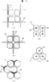
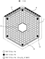
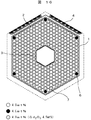
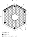
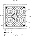
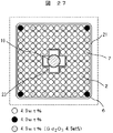
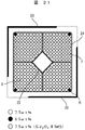
四角形の燃料集合体と、燃料集合体4体に1体の割合で燃料集合体間に挿入される十字型制御棒とを含む炉心の場合には、「隣接する4本の十字型制御棒の中心点を頂点とする正方形(図2(a)参照)の面積を4で除した値」である。四角形の燃料集合体と、燃料集合体2体に1体の割合で燃料集合体間に挿入される十字型制御棒とを含む炉心の場合には、「隣接する4本の十字型制御棒の中心点を頂点とする正方形(図2(b)参照)の面積を2で除した値」である。六角形の燃料集合体と、燃料集合体間に挿入されるY字型制御棒とを含む炉心の場合には、「隣接する3本のY字型制御棒の中心点を頂点とする正三角形(図2(c)参照)の面積を1.5 で除した値」である。四角形の燃料集合体と、燃料集合体チャンネルボックス内に挿入される丸型制御棒とを含む炉心の場合には、「隣接する4体の燃料集合体の中心点を頂点とする正方形(図2(d)参照)の面積」である。六角形の燃料集合体と、燃料集合体チャンネルボックス内に挿入される丸型又は六角制御棒とを含む炉心の場合には、「隣接する3体の燃料集合体の中心点を頂点とする正三角形(図2(e)参照)の面積に2.0 を乗じた値」である。 In the case of a reactor core that includes a rectangular fuel assembly and a cruciform control rod inserted between the fuel assemblies in a ratio of one to four fuel assemblies, the “four adjacent cruciform control rods” “A value obtained by dividing the area of a square (see FIG. 2A) having the center point as a vertex by 4”. In the case of a core including a square fuel assembly and a cross-shaped control rod inserted between two fuel assemblies at a ratio of one to two fuel assemblies, “the four adjacent cross-shaped control rods "A value obtained by dividing the area of a square (see FIG. 2B) having the center point as a vertex by 2". In the case of a reactor core that includes a hexagonal fuel assembly and Y-shaped control rods inserted between the fuel assemblies, the “equilateral triangle with the center point of three adjacent Y-shaped control rods as the vertices” The value obtained by dividing the area of (see FIG. 2C) by 1.5. In the case of a core including a quadrangular fuel assembly and a round control rod inserted into the fuel assembly channel box, “a square with the center point of four adjacent fuel assemblies as a vertex (FIG. 2). (D) reference). In the case of a reactor core that includes a hexagonal fuel assembly and a round or hexagonal control rod inserted into the fuel assembly channel box, “a positive point with the center point of the three adjacent fuel assemblies as a vertex. It is a value obtained by multiplying the area of the triangle (see FIG. 2E) by 2.0.
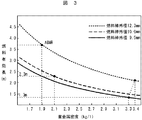
図3に、燃料棒外径、及び炉心の単位体積に含まれる重金属重量密度とをパラメータとして、ABWRと同じ平均線出力密度とするのに必要な燃料有効長を示す。燃料棒が細くなるほど、少ない重金属重量密度で燃料有効長を低くすることが出来る。なぜならば、燃料棒外径が細くなれば燃料棒1本当たりのウラン,プルトニウム,マイナーアクチニドの重金属重量を減らすことが出来るため、同じ重金属重量密度であっても燃料棒総本数を増やすことが出来るからである。現行BWRにおいて使用実績のある最小の燃料棒外径は約10mmであり、このとき平均線出力密度を増大することなく原子炉建屋を1階層低くできる燃料有効長2.3m 以下とするためには重金属重量密度をABWRの約1.9kg/l より増大し2.1kg/l 以上にする必要があるが、本願発明により熱的余裕を損なうことなく達成可能である。また重金属重量密度2.1kg/l 以上で燃料有効長を3mまで延長することにより、短尺炉心による利点を維持しつつ燃料装荷量を増加できる。これによりプラントの連続運転期間を増加させプラント利用率を向上させること、あるいは燃料体交換体数の削減による燃料経済性の向上効果が得られる。 FIG. 3 shows the effective fuel length necessary to obtain the same average linear power density as ABWR, using parameters of the outer diameter of the fuel rod and the heavy metal weight density contained in the unit volume of the core. The thinner the fuel rods, the lower the effective fuel length with less heavy metal weight density. This is because, if the fuel rod outer diameter is reduced, the weight of uranium, plutonium, and minor actinides per fuel rod can be reduced, so the total number of fuel rods can be increased even with the same heavy metal weight density. Because. The minimum fuel rod outer diameter that has been used in the current BWR is about 10 mm. At this time, in order to achieve an effective fuel length of 2.3 m or less, which can lower the reactor building by one layer without increasing the average linear power density. The heavy metal weight density needs to be increased from about 1.9 kg / l of ABWR to 2.1 kg / l or more, but this can be achieved without impairing the thermal margin by the present invention. Further, by extending the effective fuel length to 3 m at a heavy metal weight density of 2.1 kg / l or more, the fuel loading can be increased while maintaining the advantages of the short core. Thereby, the continuous operation period of the plant can be increased to improve the plant utilization rate, or the fuel economy can be improved by reducing the number of fuel exchangers.
さらに、現行PWRにおいて使用されている燃料棒外径9.5mm の燃料棒を用い、燃料棒間隙を燃料集合体の製作や熱的余裕の確保などの点からの必要最小値である0.7mm として三角格子に配列すると、平均線出力密度を増大することなく燃料有効長を1.3m まで減少(出力密度を140kW/lまで増大) できる。この場合、重金属重量密度は3.3kg/lとなり、原子炉建屋を1階層低くできる燃料有効長2.3m の炉心では連続運転期間や燃料経済性をABWRとほぼ同等にすることも可能である。一方、燃料棒間隙0.7
mmで燃料棒外径を9.5mm より太くすると、燃料有効長の低減効果は減少するが重金属重量密度を3.4kg/lまで増大できる。重金属重量密度2.1〜3.4kg/l で燃料有効長を1.0m まで短尺にすれば原子炉建屋を2階層低くすることが可能である。さらに、前述(1)の炉心に装荷する燃料集合体数を増やす方法を併用することで、連続運転期間や燃料経済性を向上することが可能となる。
In addition, the fuel rod outer diameter of 9.5mm used in the current PWR is used, and the fuel rod gap is 0.7mm, which is the necessary minimum value from the viewpoint of manufacturing the fuel assembly and ensuring thermal margin. As shown, the effective fuel length can be reduced to 1.3 m (the power density can be increased to 140 kW / l) without increasing the average linear power density. In this case, the heavy metal weight density is 3.3 kg / l, and it is possible to make the continuous operation period and fuel economy almost the same as ABWR in the core with an effective fuel length of 2.3 m that can lower the reactor building by one layer. . On the other hand, fuel rod gap 0.7
If the fuel rod outer diameter is made larger than 9.5 mm in mm, the effect of reducing the effective fuel length is reduced, but the heavy metal weight density can be increased to 3.4 kg / l. If the heavy metal weight density is 2.1 to 3.4 kg / l and the effective fuel length is shortened to 1.0 m, the reactor building can be lowered by two layers. Furthermore, by using together the method (1) of increasing the number of fuel assemblies loaded in the core, it is possible to improve the continuous operation period and fuel economy.
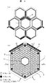
重金属重量密度を2.1〜3.4kg/l(これは(燃料有効長) ×(チャンネルボックス内水平断面積) で定義されるチャンネルボックス内領域の単位体積あたりに含まれる炉心装荷時の重金属重量密度2.8〜4.5kg/lに相当)にする際に問題となるのが、原子炉が安全に停止する能力があるかどうかを示す指標として設けられた設計基準である炉停止余裕の減少である。しかしながら、本発明では増大した未飽和及び飽和水領域を燃料集合体格子の中央部と周辺部に集中して配置しており、実効的な水対燃料体積比を増大させることなく冷温時の反応度上昇を抑制できる構成となっている。図4に重金属重量密度2.1
kg/lと3.4kg/l の場合の、冷温時反応度上昇と隣接する燃料集合体の対面するチャンネルボックス間距離の平均の関係を示す。なお隣接する燃料集合体の対面するチャンネルボックス間距離の平均は図5に示すように、四角形燃料集合体からなる炉心の場合4方向のチャンネルボックス間距離(a,b,c,d)の平均値、また六角形燃料集合体からなる炉心の場合6方向のチャンネルボックス間距離(e,f,g,h,i,j)の平均値を意味する。隣接する燃料集合体の対面するチャンネルボックス間距離の平均をABWRの約16mmよりも広い17〜40mmとすることで、燃料集合体平均濃縮度が8wt%の高燃焼度燃料集合体においても冷温時反応度上昇をABWR以下にすることが可能となる。特に、飽和水の層の厚さが19mmを超えると中性子の減速が急激に進むので、制御棒挿入のために設けられたギャップ水の幅を制御棒に必要な量より厚く、同時に燃料集合体の中央部の水ロッド領域を大きくする。燃料集合体の外と中央部で中性子を減速させ、減速された熱中性子を拡散により燃料棒格子に供給する考え方を採用することにより、燃料棒格子の二相流を中性子減速の役割から開放し、燃料棒格子の二相流を燃料棒冷却の役割に限ることが可能となる。その結果、炉心領域の40%以上を占めていた二相流の体積割合を18〜39%(チャンネルボックス内領域に対しては24〜52%)に減らすことができ、ギャップ水や水ロッドの体積割合を少し増加させても、核分裂エネルギー発生の主役である燃料物質領域の体積割合を23〜37%(チャンネルボックス内領域に対しては30〜49%)に大幅に増加させることができる。チャンネルボックス間の平均間隙増大効果は燃料集合体の形状や大きさによらず得られる一般的な知見であるが、従来のBWR炉心燃料設計では、中性子減速と除熱という軽水の二つの機能を同時に達成する構成にとらわれたため着目されてこなかった。軽水の機能を徹底的に分離する設計概念に基づく本発明ではその効果を有効に活用することが出来た。このとき炉心領域における未飽和及び飽和水領域の体積割合は26〜38%、炉心領域における制御棒挿入用のガイド棒の中,水ロッドの中の未飽和及び飽和水領域の体積割合は4%以上、特に6〜9%(チャンネルボックス内領域に対しては5%以上、特に8〜12%)、炉心領域並びにチャンネルボックス内領域における燃料集合体チャンネルボックス外側のチャンネルボックス間のギャップ,制御棒挿入用のガイド棒の中,水ロッドの中等を除くチャンネルボックス内の燃料棒冷却用のサブクール水を含む二相流冷却水の体積対燃料物質領域の体積割合の比は0.5〜1.8、燃料集合体チャンネルボックス外幅対平均燃料集合体格子幅の比は0.80〜0.89である。なお本発明では、平均燃料集合体格子幅を燃料集合体格子セル面積と等面積の正方形、あるいは正六角形とした場合の対辺間隔で定義する。また、燃料棒間隙は燃料集合体の製作や熱的余裕の確保などの点からの必要最小値である0.7 以上とし、正方格子の場合の最大値を2.6mm (三角格子の場合には燃料棒格子セルでの重金属重量密度が正方格子と同等となる3.6mm )とする。さらに、燃料集合体の内側に、燃料棒よりも太くかつ飽和水を内包する大型水ロッドを1本以上設置すれば、燃料集合体チャンネルボックスの外側と内部に未飽和及び飽和水領域を集中して設けることが出来る。これにより十分な中性子減速効果を得ることができ、冷温時反応度上昇を更に小さく抑えることが可能となる。
Heavy metal weight density 2.1-3.4kg / l (this is (fuel effective length) x (horizontal cross-sectional area in channel box) heavy metal at the time of core loading included per unit volume of channel box area) The problem with the weight density (equivalent to a weight density of 2.8 to 4.5 kg / l) is the reactor shutdown margin, which is a design standard established as an indicator of whether or not the reactor has the ability to shut down safely. Decrease. However, in the present invention, the increased unsaturated and saturated water regions are concentrated in the central and peripheral portions of the fuel assembly lattice, and the reaction at the cold temperature is increased without increasing the effective water-to-fuel volume ratio. It is the structure which can suppress a degree rise. Figure 4 shows the heavy metal weight density 2.1.
The relationship between the increase in the reactivity at the time of cold temperature and the distance between the channel boxes facing each other adjacent fuel assemblies in the case of kg / l and 3.4 kg / l is shown. As shown in FIG. 5, the average distance between adjacent channel boxes of adjacent fuel assemblies is the average of the distances (a, b, c, d) between the channel boxes in four directions in the case of a core made of a rectangular fuel assembly. In the case of a core composed of hexagonal fuel assemblies, it means the average value of the distances (e, f, g, h, i, j) in six directions in the six directions. By setting the average distance between adjacent channel boxes of adjacent fuel assemblies to 17-40 mm, which is wider than ABWR of about 16 mm, even in high burnup fuel assemblies with an average fuel assembly enrichment of 8 wt%, even when cold It is possible to increase the reactivity to ABWR or less. In particular, when the thickness of the saturated water layer exceeds 19 mm, the neutron decelerates rapidly, so that the gap water provided for inserting the control rod is wider than the amount required for the control rod, and at the same time the fuel assembly Increase the water rod area at the center of the. By adopting the concept of decelerating neutrons outside and at the center of the fuel assembly and supplying the decelerated thermal neutrons to the fuel rod lattice by diffusion, the two-phase flow of the fuel rod lattice is released from the role of neutron moderation. The two-phase flow of the fuel rod lattice can be limited to the role of fuel rod cooling. As a result, the volume ratio of the two-phase flow that occupied 40% or more of the core area can be reduced to 18 to 39% (24 to 52% for the area in the channel box). Even if the volume ratio is slightly increased, the volume ratio of the fuel material region, which is the main component of fission energy generation, can be significantly increased to 23 to 37% (30 to 49% for the channel box region). The effect of increasing the average gap between channel boxes is a general knowledge that can be obtained regardless of the shape and size of the fuel assembly, but the conventional BWR core fuel design has two functions of light water: neutron moderation and heat removal. At the same time, it was not attracted attention because it was constrained by the configuration achieved. In the present invention based on the design concept of thoroughly separating the function of light water, the effect could be effectively utilized. At this time, the volume ratio of the unsaturated and saturated water areas in the core area is 26 to 38%, the volume ratio of the unsaturated and saturated water areas in the water rod is 4% in the guide rod for inserting the control rod in the core area. Above, especially 6-9% (5% or more, especially 8-12% for the channel box area), gap between the channel box outside the fuel assembly channel box in the core area and the channel box area, control rod The ratio of the volume ratio of the two-phase flow cooling water including the subcooled water for cooling the fuel rod in the channel box excluding the inside of the guide rod for insertion and the inside of the water rod to the volume ratio of the fuel material region is 0.5 to 1.8, The ratio of the fuel assembly channel box outer width to the average fuel assembly lattice width is between 0.80 and 0.89. In the present invention, the average fuel assembly lattice width is defined as the distance between opposite sides when the square is equal to the fuel assembly lattice cell area or a regular hexagon. The fuel rod gap should be at least 0.7, which is the minimum required for manufacturing fuel assemblies and ensuring thermal margins. The maximum value for square lattices is 2.6 mm (for triangular lattices). The weight density of heavy metals in the fuel rod lattice cell is equal to that of the square lattice (3.6 mm). Furthermore, if one or more large water rods that are thicker than the fuel rods and contain saturated water are installed inside the fuel assembly, the unsaturated and saturated water regions are concentrated outside and inside the fuel assembly channel box. Can be provided. As a result, a sufficient neutron moderation effect can be obtained, and the increase in the reactivity during cold temperature can be further suppressed.
一方、このように広いチャンネルボックス間間隙を確保すると、燃料棒を除熱するための二相流軽水領域の面積がABWRよりも少なくなって、燃料除熱性能に影響が出ることが懸念される。しかし本願発明者らが考案した軽水増殖BWR(特願平8−21890号公報)において示されているように、燃料棒の単位出力あたりの流量をABWRのそれと同程度にすることで同等の除熱性能が得られることが知られている。本発明では、燃料領域を増加させているため二相流領域割合は減少するが、炉心有効長が低減でき圧力損失を増大することなく除熱に必要な冷却材を流すことができ、出力密度を50kW/l以上、特に63〜140kW/lと増大することができる。 On the other hand, if such a wide gap between the channel boxes is ensured, the area of the two-phase flow light water region for removing heat from the fuel rod is less than ABWR, which may affect the fuel heat removal performance. . However, as shown in the light water breeding BWR (Japanese Patent Application No. 8-21890) devised by the inventors of the present application, the flow rate per unit output of the fuel rod is set to the same level as that of ABWR. It is known that thermal performance can be obtained. In the present invention, since the fuel region is increased, the ratio of the two-phase flow region is reduced, but the effective length of the core can be reduced and the coolant necessary for heat removal can be flowed without increasing the pressure loss, and the power density Can be increased to 50 kW / l or more, particularly 63 to 140 kW / l.
さらに、炉心に装荷されている燃料集合体体数の制御棒駆動機構基数に対する比が3より小さい大型燃料集合体で構成される炉心では、炉停止性能が向上するため炉心領域の単位体積に含まれる炉心装荷時の重金属重量密度を、実施例において詳細に説明するようにABWRより20%以上増大(2.3〜3.4kg/lに)することができる。このとき炉心領域における燃料物質領域の体積割合は25〜37%(チャンネルボックス内領域に対しては30〜49%)、チャンネルボックス内の燃料棒冷却用のサブクール水を含む二相流の体積割合は18〜39%(チャンネルボックス内領域に対しては24〜49%)、未飽和及び飽和水領域の体積割合は23〜38%、制御棒挿入用のガイド棒の中,水ロッドの中の未飽和及び飽和水領域の体積割合は4%以上、特に7〜9%(チャンネルボックス内領域に対しては5%以上、特に9〜12%)、炉心領域並びにチャンネルボックス内領域における燃料集合体チャンネルボックス外側のチャンネルボックス間のギャップ,制御棒挿入用のガイド棒の中,水ロッドの中等を除くチャンネルボックス内の燃料棒冷却用のサブクール水を含む二相流冷却水の体積対燃料物質領域の体積割合の比は0.5〜1.6である。また、炉停止性能が向上するため平均燃料集合体格子幅を大きくすることが可能であり、燃料集合体チャンネルボックス外幅対平均燃料集合体格子幅の比は0.82〜0.91となる。燃料棒間隙は燃料集合体の製作や熱的余裕の確保などの点からの必要最小値である0.7 以上とし、正方格子の場合の最大値を2.3mm (三角格子の場合には燃料棒格子セルでの重金属重量密度が正方格子と同等となる3.3mm)とする。 Furthermore, in a core composed of large fuel assemblies in which the ratio of the number of fuel assemblies loaded in the core to the number of control rod drive mechanism radix is less than 3, it is included in the unit volume of the core region in order to improve reactor shutdown performance. As described in detail in the examples, the heavy metal weight density when the core is loaded can be increased by 20% or more (to 2.3 to 3.4 kg / l) from ABWR. At this time, the volume ratio of the fuel material area in the core area is 25 to 37% (30 to 49% for the area in the channel box), and the volume ratio of the two-phase flow including the subcool water for cooling the fuel rods in the channel box. 18-39% (24-49% for the channel box area), the volume ratio of the unsaturated and saturated water area is 23-38%, in the guide rod for inserting the control rod, in the water rod The volume fraction of the unsaturated and saturated water regions is 4% or more, particularly 7 to 9% (5% or more, especially 9 to 12% for the channel box region), and the fuel assembly in the core region and the channel box region Includes subcool water for cooling fuel rods in the channel box except for gaps between channel boxes outside the channel box, guide rods for inserting control rods, water rods, etc. The ratio of the volume ratio of the volume-to-fuel material region of the two phase flow cooling water is 0.5 to 1.6. Further, since the reactor shutdown performance is improved, the average fuel assembly lattice width can be increased, and the ratio of the fuel assembly channel box outer width to the average fuel assembly lattice width is 0.82 to 0.91. . The fuel rod gap should be at least 0.7, which is the minimum necessary for manufacturing the fuel assembly and ensuring thermal margin, and the maximum value for the square lattice is 2.3 mm. It is assumed that the heavy metal weight density in the bar lattice cell is equal to that of the square lattice (3.3 mm).
以上より、熱的余裕や安全性を現在運転中のBWRと同程度に保ちつつ、炉心の高さを大幅に低減し発電所の建設コスト低減でき、本発明の第1の目的が達成される。 As described above, while maintaining the thermal margin and safety at the same level as the BWR that is currently in operation, the height of the core can be significantly reduced and the construction cost of the power plant can be reduced, and the first object of the present invention is achieved. .
また、以下の2つの作用により、前記第2の目的が達成される。 The second object is achieved by the following two actions.
チャンネルボックスを従来のABWRよりも小さくし、かつ重金属重量密度を従来の
ABWRよりも大きくした本発明の燃料集合体では、チャンネルボックス内領域の単位体積あたりの重金属重量密度をABWRの約2.6kg/l に対して、2.8〜4.5kg/lと大きくできる。このため、燃料集合体チャンネルボックス内部の水対燃料体積比が小さくなり、ウラン238からプルトニウムへの転換量を増大出来る構成となっている。一方、プルトニウム生成量を増大するためには、従来のABWRよりも広いチャンネルボックス間間隙に存在する飽和水が問題となる。そこで、この飽和水を排除するための水排除棒、さらには制御棒上端に設置されたフォロアをチャンネルボックス間間隙等の飽和水領域に挿入することで、ウラン238からプルトニウムへの転換を増大させることが可能となり、同じウラン濃縮度の燃料を使用する時には、従来の燃料集合体に比べて高い燃焼度を実現することが出来る。これが第1の作用である。さらに、水排除棒を挿入することで水対燃料体積比を自在に調整できるので、可燃性毒物を用いることなく燃焼初期の余剰反応度の制御が可能となる。これにより、従来は可燃性毒物に吸収されていた中性子を、プルトニウムの生成に転用できるので、更に高い燃焼度を実現することが出来る。これが第2の作用である。
In the fuel assembly of the present invention in which the channel box is smaller than the conventional ABWR and the heavy metal weight density is larger than that of the conventional ABWR, the heavy metal weight density per unit volume in the region in the channel box is about 2.6 kg of ABWR. / L can be increased to 2.8 to 4.5 kg / l. For this reason, the water-to-fuel volume ratio inside the fuel assembly channel box is reduced, and the amount of conversion from uranium 238 to plutonium can be increased. On the other hand, in order to increase the amount of plutonium produced, saturated water present in the gap between channel boxes wider than the conventional ABWR becomes a problem. Therefore, the conversion from uranium 238 to plutonium is increased by inserting a water removal rod for eliminating this saturated water and further a follower installed at the upper end of the control rod into a saturated water region such as a gap between channel boxes. Therefore, when using fuel with the same uranium enrichment, it is possible to achieve a higher burnup than conventional fuel assemblies. This is the first action. Furthermore, since the water-to-fuel volume ratio can be freely adjusted by inserting a water exclusion rod, it is possible to control the excess reactivity at the initial stage of combustion without using a flammable poison. Thereby, since the neutron which was absorbed by the combustible poison in the past can be diverted to the production of plutonium, a higher burnup can be realized. This is the second action.
また、本発明の構成をABWR以前の既存炉炉心あるいはABWR炉心に適用した場合、すなわち燃料棒1本あたりの出力を変えず燃料有効長を2.3m から3.7m に増大した時には、炉心外接半径及び高さは従来のまま(出力密度は従来の50kW/l)で燃料重量密度の大きな炉心を実現することが出来る。この場合、燃料棒1本あたりの出力を一定として燃料有効長を増大しているため平均線出力密度が低減し、除熱に必要な炉心流量を大幅に低減しても熱的余裕が維持できる。その結果、本発明の第3の目的である、プラントの連続運転期間を増加させプラント利用率を向上させることが可能となる。 Further, when the configuration of the present invention is applied to an existing reactor core before ABWR or an ABWR core, that is, when the effective fuel length is increased from 2.3 m to 3.7 m without changing the output per fuel rod, A core with a high fuel weight density can be realized with the conventional radius and height (power density is 50 kW / l). In this case, since the effective fuel length is increased while keeping the output per fuel rod constant, the average linear power density is reduced, and the thermal margin can be maintained even if the core flow rate required for heat removal is greatly reduced. . As a result, it is possible to increase the plant utilization rate by increasing the continuous operation period of the plant, which is the third object of the present invention.
また本発明は、燃料集合体格子を燃料棒を冷却する稠密格子領域と中性子の減速領域の二領域に非均質化し、飽和水領域を増大し燃料集合体格子の中央部と周辺部に集中することで中性子減速効果を向上している。その結果、冷温時の反応度上昇,ボイド係数の絶対値が低減でき本発明の第4の目的である、炉停止性能,過渡・安定性特性の改善が可能となる。 The present invention also makes the fuel assembly lattice non-homogeneous in two regions, a dense lattice region for cooling the fuel rods and a neutron moderation region, increasing the saturated water region and concentrating on the central and peripheral portions of the fuel assembly lattice. The neutron moderation effect is improved. As a result, the reactivity increase at the time of cold temperature and the absolute value of the void coefficient can be reduced, and the fourth object of the present invention, the furnace shutdown performance and the transient / stability characteristics can be improved.
本発明によれば、熱的余裕や安全性を現在運転中のBWRと同程度に保ちつつ、(1)炉心の高さを大幅に低減し発電所の建設コスト低減に寄与する、(2)運転中のプルトニウム生産量を増加させ、燃料集合体の寿命を延長して燃料サイクルコスト低減に寄与する、(3)プラントの連続運転期間を増加させプラント利用率を向上させ発電コスト低減に寄与する、(4)冷温時の反応度上昇,ボイド係数の絶対値を低減して高燃焼度時に課題となる炉停止性能,過渡・安定性特性の改善に寄与する炉心が構築できる。 According to the present invention, while maintaining the thermal margin and safety at the same level as the BWR currently in operation, (1) greatly reducing the height of the core and contributing to the construction cost reduction of the power plant, (2) Increase plutonium production during operation, extend the life of the fuel assembly and contribute to fuel cycle cost reduction, (3) contribute to the reduction of power generation cost by increasing the plant operation rate by increasing the continuous operation period of the plant (4) It is possible to construct a reactor core that contributes to improvement of reactor shutdown performance and transient / stability characteristics, which are problems at high burnup, by reducing the reactivity increase during cold temperatures and the absolute value of the void coefficient.
以下、本発明の実施例を図面を用いて詳細に説明する。 Hereinafter, embodiments of the present invention will be described in detail with reference to the drawings.
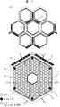
(第1の実施例)
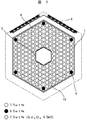
本発明の第1の実施例を図1及び図6により説明する。図6に、本実施例の電気出力
1356MWeの水平断面を示す。720体の燃料集合体5と、燃料集合体3体に1体の割合で223体のY字型制御棒4が示されている。図1に燃料集合体格子の断面を示す。燃料集合体格子は燃料棒2,6,7と水ロッド3を内包する正六角形状のチャンネルボックス1,チャンネルボックス間のギャップ領域とチャンネルボックス1の外側に配置されるY字型制御棒4から構成される。燃料集合体格子は正六角形状をしており、チャンネルボックス間距離は22.5mmである。チャンネルボックス1内には外径9.5mmの燃料棒2が燃料棒間隙1.8mmで三角格子状に配置され、燃料棒列9列の正六角形燃料集合体を形成している。燃料集合体中心部には、燃料棒列3列分、すなわち燃料棒単位格子セル19個分の領域に水ロッド3が配置されている。チャンネルボックス1内の燃料棒の本数は
198本である。Y字型制御棒4の翼には、B4C が充填されたステンレス管の吸収棒が配置されており、翼の間隔はそれぞれ120度である。燃焼初期に局所的に燃料棒出力が大きくなるコーナー部燃料棒6にはウラン濃縮度4.0wt% の燃料物質を、その他の燃料棒2にはウラン濃縮度4.9wt% の燃料物質を配置してある。また、コーナー部燃料棒6以外でも燃焼初期に出力が大きくなる傾向があるチャンネルボックス及び水ロッドに隣接している燃料棒7には4.5wt%の可燃性毒物を添加したウラン濃縮度4.9wt%の燃料物質を配置することで燃焼初期の局所出力ピーキングを抑制している。このような燃料配置を採用することにより、ペレット最高濃縮度5wt%の制約下で、局所出力ピーキングを過度に増大させることなく燃料集合体横断面平均のウラン濃縮度を4.87wt%まで高めることが可能となる。本実施例では燃料集合体横断面平均ウラン濃縮度4.87wt%の燃料物質を燃料集合体軸方向に一様に配置している。この燃料集合体を図6の炉心に装荷したときの炉心外接半径は2.9m 、燃料有効長は194cm、出力密度は83
kW/lである。炉心領域における、チャンネルボックス内の燃料棒冷却用のサブクール水を含む二相流冷却水の体積割合は27%、水ロッド中の水の体積割合は5%、チャンネルボックス外側のチャンネルボックス間のギャップと水ロッド中の水の体積割合は26%、燃料物質の体積割合は31%、二相流冷却水の体積割合と燃料物質の体積割合の比は
0.88である。炉心領域の単位体積に含まれるウラン重量は2.8kg/lである。チャンネルボックスの外幅と燃料集合体格子幅の比は0.89 である。チャンネルボックス内領域における、燃料棒冷却用のサブクール水を含む二相流冷却水の体積割合は36%、水ロッド中の水の体積割合は7%、燃料物質の体積割合は41%、二相流冷却水の体積割合と燃料物質の体積割合の比は0.88 である。チャンネルボックス内領域の単位体積に含まれるウラン重量は3.8kg/l である。
(First embodiment)
A first embodiment of the present invention will be described with reference to FIGS. In FIG. 6, the horizontal cross section of the electrical output 1356MWe of a present Example is shown. 720
kW / l. In the core region, the volume ratio of the two-phase flow cooling water including the subcooled water for cooling the fuel rods in the channel box is 27%, the volume ratio of the water in the water rod is 5%, and the gap between the channel boxes outside the channel box The volume ratio of water in the water rod is 26%, the volume ratio of the fuel material is 31%, and the ratio of the volume ratio of the two-phase cooling water to the volume ratio of the fuel material is 0.88. The weight of uranium contained in the unit volume of the core region is 2.8 kg / l. The ratio of the outer width of the channel box to the fuel assembly lattice width is 0.89. In the area inside the channel box, the volume ratio of the two-phase flow cooling water including the subcooled water for cooling the fuel rod is 36%, the volume ratio of the water in the water rod is 7%, the volume ratio of the fuel material is 41%, the two-phase The ratio of the volume ratio of the flow cooling water to the volume ratio of the fuel material is 0.88. The weight of uranium contained in the unit volume of the channel box area is 3.8 kg / l.
次に、本実施例の作用を説明する。 Next, the operation of this embodiment will be described.
本実施例では、六角形燃料集合体に沸騰水型軽水炉及び加圧水型軽水炉において使用実績のある外径9.5mmの燃料棒を間隙1.8mmの三角格子状に稠密配置し、燃料棒総本数を増やして単位体積に含まれるウラン重量を炉心平均でABWRの1.9kg/l より約47%増大した2.8kg/l とすることにより、燃料有効長がABWRの3.7mより約1.8m低い1.94m の軽水炉が実現する。その結果、出力をABWRと同じ1356MWe、炉心外接半径をABWRとほぼ同じ2.9m とした軽水炉において、ABWRと比較して燃料有効長を約1.8m 低減することが可能となり、原子炉建屋高さを約10m低くできる。また、本実施例では、チャンネルボックス間距離をABWRの16mmより広い22.5mmとすることにより冷温時反応度上昇を抑えることができ、炉停止余裕を1.0%Δk 以上とすることができる。中性子減速効果を向上することでボイド係数は−6.0 ×10⁻⁴Δk/k%void となり、ABWRのボイド係数−8.0×10⁻⁴Δk/k/%voidと比較して絶対値が小さい軽水炉が実現できる。また、本実施例では、外径9.5mm の燃料棒を燃料棒間隙1.8mm の三角格子状に配置し、燃料棒総本数を増やして平均線出力密度を
ABWR(炉心に装荷されている全燃料集合体が9×9格子燃料集合体の場合)の172W/cmより約17%低い142W/cmとすることにより、MCPR1.3 以上を確保することができ、ABWRと同程度の除熱性能を確保できる。
In this embodiment, fuel rods with an outer diameter of 9.5 mm that have been used in boiling water reactors and pressurized water reactors are arranged densely in a triangular lattice with a gap of 1.8 mm in the hexagonal fuel assembly, and the total number of fuel rods By increasing the weight of uranium contained in the unit volume to 2.8 kg / l, which is about 47% higher than the ABWR of 1.9 kg / l on the core average, the effective fuel length is about 1.75 m from ABWR of 3.7 m. A 1.94m light water reactor, 8m lower, will be realized. As a result, in a light water reactor with an output of 1356 MWe, the same as ABWR, and a core circumscribing radius of 2.9 m, which is about the same as ABWR, the effective fuel length can be reduced by about 1.8 m compared to ABWR. The height can be lowered by about 10 m. Further, in this embodiment, by setting the distance between channel boxes to 22.5 mm, which is wider than 16 mm of ABWR, it is possible to suppress an increase in cold temperature reactivity and to make the furnace shutdown margin 1.0% Δk or more. By improving the neutron moderation effect, the void coefficient becomes −6.0 × 10 −4 Δk / k% void, which is an absolute value compared to the ABWR void coefficient of −8.0 × 10 −4 Δk / k /% void. A small water reactor can be realized. Further, in this embodiment, fuel rods having an outer diameter of 9.5 mm are arranged in a triangular lattice shape with a fuel rod gap of 1.8 mm, the total number of fuel rods is increased, and the average linear power density is ABWR (loaded in the core). MCPR of 1.3 or more can be secured by making it about 142% lower than 172 W / cm (when the total fuel assembly is a 9 × 9 lattice fuel assembly), and heat removal at the same level as ABWR Performance can be secured.
従って、本実施例により、熱的余裕や安全性をABWRと同程度に保ちつつ、炉心の高さを大幅に低減し発電所の建設コスト低減に寄与する軽水炉を実現できる。さらに、熱的余裕や安全性を現在運転中のABWRと同程度に保ちつつ、冷温時の反応度上昇,ボイド係数の絶対値を低減して高燃焼度時に課題となる炉停止性能,過渡・安定性特性を改善できる。 Therefore, according to the present embodiment, it is possible to realize a light water reactor that contributes to a reduction in the construction cost of a power plant by significantly reducing the height of the core while keeping thermal margin and safety at the same level as ABWR. In addition, while maintaining thermal margin and safety at the same level as the ABWR currently in operation, the reactor stoppage performance, transient / Stability characteristics can be improved.
さらに、本実施例において燃料有効長を381cmに増大すると、原子炉建屋高さはABWRと同等となるが、連続運転期間13ケ月におけるサイクル毎の取り替え体数が65体となり、取り出し燃焼度65Gd/tで燃料平均燃焼日数4423日の超長寿命炉心とすることができる。また、燃料有効長を381cmに増大し、サイクル毎の取り替え体数を313体とすることで、取り出し燃焼度48Gd/t、連続運転期間46ヶ月の超長期運転サイクルとすることができる。 Further, when the effective fuel length is increased to 381 cm in this embodiment, the reactor building height becomes equivalent to ABWR, but the number of replacement bodies per cycle in the continuous operation period of 13 months becomes 65, and the burnup burnup is 65 Gd / At t, an ultra-long life core with an average fuel combustion period of 4423 days can be obtained. Further, by increasing the effective fuel length to 381 cm and setting the number of replacement bodies per cycle to 313, it is possible to achieve an ultra-long-term operation cycle with a take-off burnup of 48 Gd / t and a continuous operation period of 46 months.
本実施例では、電気出力1356MWeの炉心についての構成,作用,効果を述べているが、出力規模はこれに限定されるものではない。燃料集合体の体数を変更することで、他の出力規模にも適用できる。以下の実施例も同様である。 In the present embodiment, the configuration, operation, and effect of the core having an electrical output of 1356 MWe are described, but the output scale is not limited to this. By changing the number of fuel assemblies, it can be applied to other power scales. The same applies to the following embodiments.
本実施例では、燃料物質として軽水炉で使用されている低濃縮ウラン燃料を用いた場合についての構成,作用,効果を述べている。しかし、低濃縮ウラン燃料のかわりに、使用済み燃料を再処理して得られるプルトニウムを、軽水炉で使用される濃縮ウラン製造時にその残渣として発生する劣化ウランもしくは使用済み燃料から回収される減損ウランもしくは低濃縮ウランもしくは天然ウランに富化した混合酸化物燃料や、低除染再処理時に同伴するマイナーアクチニドを含む再処理プルトニウムを、劣化ウランもしくは減損ウランもしくは低濃縮ウランもしくは天然ウランに富化した混合酸化物燃料でも同等の効果が得られる。以下の実施例も同様である。 In the present embodiment, the configuration, operation, and effect when using low enriched uranium fuel used in a light water reactor as a fuel material are described. However, instead of low-enriched uranium fuel, plutonium obtained by reprocessing spent fuel is used to produce depleted uranium produced as a residue during the production of enriched uranium used in light water reactors or depleted uranium recovered from spent fuel or Low enriched or natural uranium-enriched mixed oxide fuel and reprocessed plutonium containing minor actinides that accompany low decontamination reprocessing are mixed with depleted or depleted uranium or enriched uranium or natural uranium The same effect can be obtained with oxide fuel. The same applies to the following embodiments.
本実施例では、ウラン濃縮度あるいは核分裂性プルトニウム富化度を燃料集合体軸方向に一様に配置した場合についての構成,作用,効果を述べた。しかしながら、ウラン濃縮度あるいは核分裂性プルトニウム富化度の燃料集合体軸方向分布はこれに限定されるものではない。燃料集合体軸方向に異なるウラン濃縮度分布あるいは核分裂性プルトニウム富化度分布を持つ燃料集合体、あるいは燃料領域の上下端に劣化ウランもしくは減損ウランもしくは天然ウランからなるブランケット領域を持つ燃料集合体を採用しても本実施例と同様の効果が得られる。また、複数の燃料有効長を持つ燃料棒から構成される燃料集合体を採用しても同様の効果が得られる。以下の実施例も同様である。 In the present embodiment, the configuration, operation, and effect when the uranium enrichment or the fissile plutonium enrichment is uniformly arranged in the fuel assembly axial direction have been described. However, the fuel assembly axial distribution of uranium enrichment or fissile plutonium enrichment is not limited to this. Fuel assemblies with different uranium enrichment distributions or fissile plutonium enrichment distributions in the axial direction of the fuel assemblies, or fuel assemblies with blanket regions consisting of degraded uranium, depleted uranium, or natural uranium at the upper and lower ends of the fuel region Even if it is adopted, the same effect as in this embodiment can be obtained. The same effect can be obtained even when a fuel assembly composed of fuel rods having a plurality of effective fuel lengths is employed. The same applies to the following embodiments.
(第2の実施例)
本発明の第2の実施例を以下に説明する。本実施例は、実施例1の構成をベースに、高濃縮度燃料を用い高燃焼度化を達成しプラント利用率を増大したものである。
(Second embodiment)
A second embodiment of the present invention will be described below. In the present embodiment, based on the configuration of the first embodiment, a high burnup is achieved using a highly enriched fuel, and the plant utilization rate is increased.
本実施例は、電気出力1356MWeで、炉心は実施例1の図6と同じ構成で、720体の燃料集合体と、燃料集合体3体に1体の割合で223体のY字型制御棒を配置している。図7に燃料集合体格子の断面を示す。燃料集合体格子は燃料棒8,9,10と水ロッド3を内包する正六角形状のチャンネルボックス1とチャンネルボックス間のギャップ領域とチャンネルボックス1の外側に配置されるY字型制御棒4から構成される。燃料集合体格子は正六角形状をしており、チャンネルボックス間距離は39.0mm である。チャンネルボックス1内には外径9.5mmの燃料棒2が燃料棒間隙1.8mmで三角格子状に配置され、燃料棒列9列の正六角形燃料集合体を形成している。燃料集合体中心部には、燃料棒列3列分、すなわち燃料棒単位格子セル19個分の領域に水ロッド3が配置されている。チャンネルボックス1内の燃料棒の本数は198本である。Y字型制御棒4の翼には、
B4C が充填されたステンレス管の吸収棒が配置されており、翼の間隔はそれぞれ120度である。燃焼初期に局所的に燃料棒出力が大きくなるコーナー部燃料棒9にはウラン濃縮度6.5wt%の燃料物質を、その他の燃料棒8にはウラン濃縮度7.5wt%の燃料物質を配置してある。また、コーナー部燃料棒9以外でも燃焼初期に出力が大きくなる傾向があるチャンネルボックス及び水ロッドに隣接している燃料棒10には4.5wt% の可燃性毒物を添加したウラン濃縮度7.5wt% の燃料物質を配置することで燃焼初期の局所出力ピーキングを抑制している。燃料集合体横断面平均のウラン濃縮度は7.47wt%である。本実施例では燃料集合体横断面平均ウラン濃縮度7.47wt% の燃料物質を燃料集合体軸方向に一様に配置している。この燃料集合体を図6と同じ構成の炉心に装荷したときの炉心外接半径は3.2m 、燃料有効長は194cm、出力密度は71kW/lである。炉心領域における、チャンネルボックス内の燃料棒冷却用のサブクール水を含む二相流冷却水の体積割合は23%、水ロッド中の水の体積割合は4%、チャンネルボックス外側のチャンネルボックス間のギャップと水ロッド中の水の体積割合は37%、燃料物質の体積割合は26%、二相流冷却水の体積割合と燃料物質の体積割合の比は0.88 である。炉心領域の単位体積に含まれるウラン重量は2.4kg/l である。チャンネルボックスの外幅と燃料集合体格子幅の比は0.82 である。チャンネルボックス内領域における、燃料棒冷却用のサブクール水を含む二相流冷却水の体積割合は36%、水ロッド中の水の体積割合は7%、燃料物質の体積割合は41%、二相流冷却水の体積割合と燃料物質の体積割合の比は0.88 である。チャンネルボックス内領域の単位体積に含まれるウラン重量は3.8kg/lである。
The present embodiment has an electrical output of 1356 MWe, the core has the same configuration as that of FIG. 6 of the first embodiment, 720 fuel assemblies, and 223 Y-shaped control rods in a ratio of one to three fuel assemblies. Is arranged. FIG. 7 shows a cross section of the fuel assembly lattice. The fuel assembly lattice includes a regular
Stainless steel absorption rods filled with B 4 C are arranged, and the blade spacing is 120 degrees. A fuel material with a uranium enrichment of 6.5 wt% is arranged in the
本実施例では、燃料集合体横断面平均ウラン濃縮度を実施例1の4.87wt%から
7.47wt% として取り出し燃焼度を増加させることにより、実施例1と比較してプラント利用率が増大した軽水炉が実現する。
In this embodiment, the fuel assembly cross-sectional average uranium enrichment is increased from 4.87 wt% in the first embodiment to 7.47 wt%, and the burnup is increased to increase the plant utilization rate compared to the first embodiment. A light water reactor is realized.
本実施例では、炉心領域の単位体積に含まれるウラン重量をABWRの1.9kg/l より約26%増大した2.4kg/l とすることにより、燃料有効長がABWRの3.7m より約1.8m 低い1.94m の軽水炉が実現する。また、チャンネルボックス間距離を
ABWRの16mmより広い39.0mm とすることにより、冷温時反応度上昇を抑えることができる。また、本実施例においても実施例1と同様に、外径9.5mm の燃料棒を燃料棒間隙1.8mm の三角格子状に配置し、燃料棒総本数を増やして平均線出力密度をABWRの172W/cmより約17%低い142W/cmとすることにより、MCPR1.3 以上を確保することができ、ABWRと同程度の除熱性能を確保できる。
In this embodiment, the effective fuel length is about 3.7 m from ABWR by setting the weight of uranium contained in the unit volume in the core region to 2.4 kg / l, which is about 26% higher than 1.9 kg / l of ABWR. A light water reactor of 1.94m lower than 1.8m will be realized. Further, by setting the distance between channel boxes to 39.0 mm, which is wider than 16 mm of ABWR, it is possible to suppress an increase in the reactivity at the time of cold temperature. Also in this embodiment, as in the first embodiment, fuel rods having an outer diameter of 9.5 mm are arranged in a triangular lattice shape with a fuel rod gap of 1.8 mm, the total number of fuel rods is increased, and the average linear power density is increased to ABWR. By setting 142 W / cm, which is about 17% lower than 172 W / cm, MCPR of 1.3 or more can be secured, and heat removal performance comparable to ABWR can be secured.
以上の理由により、熱的余裕や安全性をABWRと同程度に保ちつつ、炉心の高さを大幅に低減し発電所の建設コスト低減に寄与する軽水炉を実現できる。さらに、熱的余裕や安全性を現在運転中のABWRと同程度に保ちつつ、冷温時の反応度上昇,ボイド係数の絶対値を低減して高燃焼度時に課題となる炉停止性能,過渡・安定性特性を改善できる。 For the above reasons, it is possible to realize a light water reactor that significantly reduces the height of the core and contributes to the reduction of the construction cost of the power plant while maintaining the thermal margin and safety at the same level as ABWR. In addition, while maintaining thermal margin and safety at the same level as the ABWR currently in operation, the reactor stoppage performance, transient / Stability characteristics can be improved.
(第3の実施例)
本発明の第3の実施例を図8,図9により説明する。本実施例は、実施例1,2と異なり燃料集合体格子水平断面が正六角形でない場合に適用したものである。電気出力1356
MWeで、炉心は実施例1と同様に720体の燃料集合体と、燃料集合体3体に1体の割合で223体のY字型制御棒から構成されている。
(Third embodiment)
A third embodiment of the present invention will be described with reference to FIGS. Unlike the first and second embodiments, the present embodiment is applied when the fuel assembly lattice horizontal section is not a regular hexagon. Electrical output 1356
In the MWe, the core is composed of 720 fuel assemblies and 223 Y-shaped control rods in a ratio of one to three fuel assemblies as in the first embodiment.
図8に燃料集合体6体の配置とその中の1体の燃料集合体格子の断面を示す。燃料集合体格子は燃料棒2,6,7と水ロッド3を内包する正六角形状のチャンネルボックス1とチャンネルボックス間のギャップ領域とチャンネルボックス1の外側に配置されるY字型制御棒4から構成される。図8の燃料集合体格子は、チャンネルボックス1の六辺と燃料集合体格子との間隙をk,m,n,p,q,rとしたとき、Y字型制御棒4が挿入される側の間隙k,mとチャンネルボックス1をはさんで反対側の間隙p,qが残りの2つの間隙n,rより長い縦長の六角形状をしており、チャンネルボックス1の中心と燃料集合体格子の中心は同一である。間隙kとmとpとqは等しく、また、間隙nとrは等しい。Y字型制御棒4が挿入される側の2辺のチャンネルボックス間距離は24.1mm(kの二倍) 、残りの4辺のチャンネルボックス間距離は21.6mm(k+n)であり、チャンネルボックス間の平均距離は22.4mm である。チャンネルボックス1内には外径9.5mm の燃料棒2が燃料棒間隙1.8mm で三角格子状に配置され、燃料棒列9列の正六角形燃料集合体を形成している。燃料集合体中心部には、燃料棒列3列分、すなわち燃料棒単位格子セル19個分の領域に水ロッド3が配置されている。チャンネルボックス1内の燃料棒の本数は198本である。Y字型制御棒4の翼には、B4C が充填されたステンレス管の吸収棒が配置されており、翼の間隔はそれぞれ120度である。
FIG. 8 shows an arrangement of six fuel assemblies and a cross section of one fuel assembly lattice. The fuel assembly lattice includes a regular
本実施例のもう一つの燃料集合体構成として、図9に燃料集合体6体の配置とその中の1体の燃料集合体格子の断面を示す。図9の燃料集合体格子は、Y字型制御棒4が挿入される側の間隙k,mが残りの4つ間隙n,p,q,rより長い縦長の六角形状をしている。間隙kとmは等しく、また、間隙nとpとqとrは等しい。Y字型制御棒4が挿入される側の2辺のチャンネルボックス間距離は29.1mm(kの二倍) 、残りの4辺のチャンネルボックス間距離は19.1mm(nの二倍)であり、チャンネルボックス間の平均距離は
22.4mm である。チャンネルボックス1及びチャンネルボックス1内の燃料棒2,6,7と水ロッド3の形状,配置は図8と同一である。
As another fuel assembly configuration of the present embodiment, FIG. 9 shows an arrangement of six fuel assemblies and a cross section of one fuel assembly lattice. The fuel assembly lattice of FIG. 9 has a vertically long hexagonal shape in which the gaps k and m on the side where the Y-shaped
この燃料集合体を図6の炉心に装荷したときの炉心外接半径は2.9m 、燃料有効長は194cm、出力密度は83kW/lである。炉心領域における、チャンネルボックス内の燃料棒冷却用のサブクール水を含む二相流冷却水の体積割合は27%、水ロッド中の水の体積割合は5%、チャンネルボックス外側のチャンネルボックス間のギャップと水ロッド中の水の体積割合は26%、燃料物質の体積割合は31%、二相流冷却水の体積割合と燃料物質の体積割合の比は0.88 である。炉心領域の単位体積に含まれるウラン重量は
2.8kg/l である。チャンネルボックスの外幅と縦長の六角形状燃料集合体の3つの格子幅を平均して得られる平均の燃料集合体格子幅の比は0.89 である。チャンネルボックス内領域における、燃料棒冷却用のサブクール水を含む二相流冷却水の体積割合は36%、水ロッド中の水の体積割合は7%、燃料物質の体積割合は41%、二相流冷却水の体積割合と燃料物質の体積割合の比は0.88 である。チャンネルボックス内領域の単位体積に含まれるウラン重量は3.8kg/l である。燃料集合体内の燃料物質配置は、実施例1と同じであり、燃料集合体横断面平均ウラン濃縮度4.87wt% の燃料物質を燃料集合体軸方向に一様に配置している。
When this fuel assembly is loaded on the core of FIG. 6, the core outer radius is 2.9
本実施例においても実施例1と同様に、炉心領域の単位体積に含まれるウラン重量を
ABWRの1.9kg/lより約47%増大した2.8kg/lとすることにより、燃料有効長がABWRの3.7mより約1.8m低い1.94m の軽水炉が実現する。また、チャンネルボックス間の平均距離をABWRの16mmより広い22.4mm とすることにより、冷温時反応度上昇を抑えるとともに、ボイド係数が−6.0×10⁻⁴Δk/k%void とABWRより絶対値が小さい軽水炉を実現できる。また、本実施例においても実施例1と同様に、外径9.5mm の燃料棒を燃料棒間隙1.8mm の三角格子状に配置し、燃料棒総本数を増やして平均線出力密度をABWRの172W/cmより約17%低い142W/cmとすることにより、MCPR1.3 以上を確保することができ、ABWRと同程度の除熱性能を確保できる。
In this embodiment, as in the first embodiment, the effective fuel length is increased by setting the uranium weight contained in the unit volume of the core region to 2.8 kg / l, which is about 47% higher than the 1.9 kg / l of ABWR. A 1.94m light water reactor will be realized, which is about 1.8m lower than ABWR's 3.7m. In addition, by setting the average distance between channel boxes to 22.4 mm, which is wider than 16 mm of ABWR, it is possible to suppress an increase in the reactivity during cold temperature and the void coefficient is −6.0 × 10 −4 Δk / k% void and ABWR A light water reactor with a small absolute value can be realized. Also in this embodiment, as in the first embodiment, fuel rods having an outer diameter of 9.5 mm are arranged in a triangular lattice shape with a fuel rod gap of 1.8 mm, the total number of fuel rods is increased, and the average linear power density is increased to ABWR. By setting 142 W / cm, which is about 17% lower than 172 W / cm, MCPR of 1.3 or more can be secured, and heat removal performance comparable to ABWR can be secured.
以上の理由により、熱的余裕や安全性をABWRと同程度に保ちつつ、炉心の高さを大幅に低減し発電所の建設コスト低減に寄与する軽水炉を実現できる。さらに、熱的余裕や安全性を現在運転中のABWRと同程度に保ちつつ、冷温時の反応度上昇,ボイド係数の絶対値を低減して高燃焼度時に課題となる炉停止性能,過渡・安定性特性を改善できる。 For the above reasons, it is possible to realize a light water reactor that significantly reduces the height of the core and contributes to the reduction of the construction cost of the power plant while maintaining the thermal margin and safety at the same level as ABWR. In addition, while maintaining thermal margin and safety at the same level as the ABWR currently in operation, the reactor stoppage performance, transient / Stability characteristics can be improved.
(第4の実施例)
本発明の第4の実施例を図10により説明する。本実施例は、実施例1の構成をベースに、低濃縮ウラン燃料のかわりに、濃縮ウラン製造時にその残渣として発生する劣化ウランに使用済み燃料を再処理して得られるプルトニウムを富化した混合酸化物燃料を採用したものである。
(Fourth embodiment)
A fourth embodiment of the present invention will be described with reference to FIG. This example is based on the configuration of Example 1, and instead of low-enriched uranium fuel, a mixture enriched with plutonium obtained by reprocessing spent fuel into depleted uranium generated as a residue when producing enriched uranium. Oxide fuel is used.
本実施例は、電気出力1356MWeで、炉心の水平断面の断面図は実施例1の図6と同じである。図10に燃料集合体格子の断面を示す。燃料集合体格子内のチャンネルボックス1,燃料棒12,13,14,水ロッド3,Y字型制御棒4の配置,形状,大きさは実施例1と同じである。燃焼初期に局所的に燃料棒出力が大きくなるコーナー部燃料棒
13には核分裂性Pu富化度5.0wt% の燃料物質を、その他の燃料棒12には核分裂性Pu富化度5.9wt% の燃料物質を配置してある。また、コーナー部燃料棒13以外でも燃焼初期に出力が大きくなる傾向があるチャンネルボックス及び水ロッドに隣接している燃料棒14には4.5wt%の可燃性毒物を添加した核分裂性Pu富化度5.9wt%に燃料物質を配置することで燃焼初期の局所出力ピーキングを抑制している。本実施例では燃料集合体横断面平均核分裂性Pu富化度5.87wt% の燃料物質を燃料集合体軸方向に一様に配置している。本実施例の炉心外接半径は2.9m 、燃料有効長は194cm、出力密度は83kW/l、炉心領域の単位体積に含まれるウランとプルトニウムの合計重量は2.8kg/l である。また、チャンネルボックス内領域の単位体積に含まれるウランとプルトニウムの合計重量は3.8kg/l である。
This example has an electrical output of 1356 MWe, and the cross-sectional view of the horizontal cross section of the core is the same as that of FIG. FIG. 10 shows a cross section of the fuel assembly lattice. The arrangement, shape, and size of the
本実施例では、炉心領域の単位体積に含まれるウランとプルトニウムの合計重量を2.8
kg/lとすることにより、燃料有効長がABWRの3.7mより約1.8m 低い1.94mの軽水炉が実現する。また、チャンネルボックス間距離をABWRの16mmより広い22.5mmとすることにより、冷温時反応度上昇を抑えることができ、炉停止余裕を1.0%Δk 以上とすることができる。また、本実施例においても実施例1と同様に、外径9.5mm の燃料棒を燃料棒間隙1.8mm の三角格子状に配置し、燃料棒総本数を増やして平均線出力密度をABWRの172W/cmより約17%低い142W/cmとすることにより、MCPR
1.3以上を確保することができ、ABWRと同程度の除熱性能を確保できる。
In this example, the total weight of uranium and plutonium contained in the unit volume of the core region is 2.8.
By setting the weight to kg / l, a light water reactor having a fuel effective length of 1.94 m, which is about 1.8 m lower than 3.7 m of ABWR, is realized. Further, by setting the distance between channel boxes to 22.5 mm, which is wider than 16 mm of ABWR, it is possible to suppress an increase in the reactivity at the time of cold temperature and to make the furnace shutdown margin 1.0% Δk or more. Also in this embodiment, as in the first embodiment, fuel rods having an outer diameter of 9.5 mm are arranged in a triangular lattice shape with a fuel rod gap of 1.8 mm, the total number of fuel rods is increased, and the average linear power density is increased to ABWR. MCPR by setting it to 142 W / cm, which is about 17% lower than 172 W / cm
1.3 or more can be secured, and heat removal performance comparable to ABWR can be secured.
以上の理由により、熱的余裕や安全性をABWRと同程度に保ちつつ、炉心の高さを大幅に低減し発電所の建設コスト低減に寄与する軽水炉を実現できる。 For the above reasons, it is possible to realize a light water reactor that significantly reduces the height of the core and contributes to the reduction of the construction cost of the power plant while maintaining the thermal margin and safety at the same level as ABWR.
(第5の実施例)
本発明の第5の実施例を図11,図12により説明する。本実施例は、実施例1の構成をベースに、チャンネルボックス間間隙に配置されたY字型制御棒のかわりに、燃料集合体中心部に太径丸棒制御棒を配置したものである。
(Fifth embodiment)
A fifth embodiment of the present invention will be described with reference to FIGS. In the present embodiment, a large-diameter round rod control rod is arranged at the center of the fuel assembly instead of the Y-shaped control rod arranged in the gap between the channel boxes based on the configuration of the first embodiment.
図11に、本実施例の電気出力1356MWeの水平断面を示す。720体の燃料集合体5と、燃料集合体3体に挿入される太径丸棒制御棒を1つの制御棒駆動機構で作動させる223基の制御棒駆動機構15が示されている。図12に燃料集合体格子の断面を示す。燃料集合体格子は燃料棒2,6,7と水ロッド3と太径丸棒制御棒16を内包する正六角形状のチャンネルボックス1とチャンネルボックス間のギャップ領域から構成される。チャンネルボックス間距離は22.5mmである。チャンネルボックス1内には外径9.5mmの燃料棒2が燃料棒間隙1.8mm で三角格子状に配置され、燃料棒列9列の正六角形燃料集合体を形成している。燃料集合体中心部には、燃料棒列3列分、すなわち、燃料棒単位格子セル19個分の領域に、制御棒挿入時に太径丸棒制御棒16が入る水ロッド3が配置されている。チャンネルボックス1内の燃料棒の本数は198本である。太径丸棒制御棒16はB4C が充填されたステンレス管の吸収棒で構成されている。この燃料集合体を図11の炉心に装荷したときの炉心外接半径は2.9m 、燃料有効長は194cm、出力密度は83kW/lである。炉心領域における、チャンネルボックス内の燃料棒冷却用のサブクール水を含む二相流冷却水の体積割合は27%、水ロッド中の水の体積割合は5%、チャンネルボックス外側のチャンネルボックス間のギャップと水ロッド中の水の体積割合は26%、燃料物質の体積割合は31%、二相流冷却水の体積割合と燃料物質の体積割合の比は0.88 である。炉心領域の単位体積に含まれるウラン重量は2.8kg/l である。チャンネルボックスの外幅と燃料集合体格子幅の比は0.89 である。チャンネルボックス内領域における、燃料棒冷却用のサブクール水を含む二相流冷却水の体積割合は36%、水ロッド中の水の体積割合は7%、燃料物質の体積割合は41%、二相流冷却水の体積割合と燃料物質の体積割合の比は0.88 である。チャンネルボックス内領域の単位体積に含まれるウラン重量は3.8kg/l である。燃料集合体内の燃料物質配置は、実施例1と同じであり、燃料集合体横断面平均ウラン濃縮度4.87wt% の燃料物質を燃料集合体軸方向に一様に配置している。
In FIG. 11, the horizontal cross section of the electrical output 1356MWe of a present Example is shown. Shown are 720
本実施例では、燃料集合体に配置された水ロッドをガイドチューブとして利用する太径丸棒制御棒を採用している。制御棒を太径化することにより、制御棒の機械的強度が増し、制御棒の挿入及び引き抜き時の曲がりや座屈を抑制することができる。また、燃料集合体あたりの吸収棒の本数を減らすことにより、制御棒の製造性が容易となり、製造コストが低減できる。 In this embodiment, a large-diameter round bar control rod that uses a water rod arranged in the fuel assembly as a guide tube is employed. By increasing the diameter of the control rod, the mechanical strength of the control rod increases, and bending and buckling during insertion and withdrawal of the control rod can be suppressed. Further, by reducing the number of absorption rods per fuel assembly, the control rods can be easily manufactured and the manufacturing costs can be reduced.
本実施例においても実施例1と同様に、炉心領域の単位体積に含まれるウラン重量を
ABWRの1.9kg/lより約47%増大した2.8kg/lとすることにより、燃料有効長がABWRの3.7m より約1.8m低い1.94mの軽水炉が実現する。また、チャンネルボックス間距離をABWRの16mmより広い22.5mm とすることにより、冷温時反応度上昇を抑えるとともに、ボイド係数が−6.0×10⁻⁴Δk/k%void とABWRより絶対値が小さい軽水炉を実現できる。また、本実施例においても実施例1と同様に、外径9.5mm の燃料棒を燃料棒間隙1.8mm の三角格子状に配置し、燃料棒総本数を増やして平均線出力密度をABWRの172W/cmより約17%低い142W/cmとすることにより、MCPR1.3以上を確保することができ、ABWRと同程度の除熱性能を確保できる。
In this embodiment, as in the first embodiment, the effective fuel length is increased by setting the uranium weight contained in the unit volume of the core region to 2.8 kg / l, which is about 47% higher than the 1.9 kg / l of ABWR. A 1.94m light water reactor will be realized, which is about 1.8m lower than 3.7m of ABWR. In addition, by setting the distance between channel boxes to 22.5 mm, which is wider than 16 mm of ABWR, it is possible to suppress the increase in reactivity during cold temperature and the void coefficient is −6.0 × 10 −4 Δk / k% void, which is an absolute value from ABWR. Can realize a light water reactor with small size. Also in this embodiment, as in the first embodiment, fuel rods having an outer diameter of 9.5 mm are arranged in a triangular lattice shape with a fuel rod gap of 1.8 mm, the total number of fuel rods is increased, and the average linear power density is increased to ABWR. By setting 142 W / cm, which is about 17% lower than 172 W / cm, MCPR of 1.3 or more can be secured, and heat removal performance comparable to ABWR can be secured.
以上の理由により、熱的余裕や安全性をABWRと同程度に保ちつつ、炉心の高さを大幅に低減し発電所の建設コスト低減に寄与する軽水炉を実現できる。さらに、熱的余裕や安全性を現在運転中のABWRと同程度に保ちつつ、冷温時の反応度上昇,ボイド係数の絶対値を低減して高燃焼度時に課題となる炉停止性能,過渡・安定性特性を改善できる。 For the above reasons, it is possible to realize a light water reactor that significantly reduces the height of the core and contributes to the reduction of the construction cost of the power plant while maintaining the thermal margin and safety at the same level as ABWR. In addition, while maintaining thermal margin and safety at the same level as the ABWR currently in operation, the reactor stoppage performance, transient / Stability characteristics can be improved.
(第6の実施例)
本発明の第6の実施例を図13,図14により説明する。本実施例は、実施例5の構成をベースに、燃料の装荷量を増大したものである。
(Sixth embodiment)
A sixth embodiment of the present invention will be described with reference to FIGS. In this embodiment, the amount of fuel loaded is increased based on the configuration of the fifth embodiment.
図13に、本実施例の電気出力1356MWeの水平断面を示す。504体の燃料集合体5と、燃料集合体3体に挿入される太径丸棒制御棒を1つの制御棒駆動機構で作動させる157基の制御棒駆動機構15が示されている。図14に燃料集合体格子の断面を示す。燃料集合体格子は燃料棒2,6,7と水ロッド3と太径丸棒制御棒16を内包する正六角形状のチャンネルボックス1,チャンネルボックス間のギャップ領域から構成される。チャンネルボックス間距離は22.5mmである。チャンネルボックス1内には外径9.5mmの燃料棒2が燃料棒間隙1.7mmで三角格子状に配置され、燃料棒列11列の正六角形燃料集合体を形成している。燃料集合体中心部には、燃料棒列4列分、すなわち、燃料棒単位格子セル37個分の領域に、制御棒挿入時に太径丸棒制御棒16が入る水ロッド3が配置されている。チャンネルボックス1内の燃料棒の本数は294本である。太径丸棒制御棒16はB4C が充填されたステンレス管の吸収棒で構成されている。燃焼初期に局所的に燃料棒出力が大きくなるコーナー部燃料棒6にはウラン濃縮度4.0wt% の燃料物質を、その他の燃料棒2にはウラン濃縮度4.9wt% の燃料物質を配置してある。また、コーナー部燃料棒6以外でも燃焼初期に出力が大きくなる傾向があるチャンネルボックス及び水ロッドに隣接している燃料棒7には4.5wt% の可燃性毒物を添加したウラン濃縮度4.9wt% の燃料物質を配置することで燃焼初期の局所出力ピーキングを抑制している。燃料集合体横断面平均のウラン濃縮度は4.88wt% である。本実施例では燃料集合体横断面平均ウラン濃縮度4.88wt% の燃料物質を燃料集合体軸方向に一様に配置している。この燃料集合体を図13の炉心に装荷したときの炉心外接半径は2.9m、燃料有効長は194cm、出力密度は85kW/lである。炉心領域における、チャンネルボックス内の燃料棒冷却用のサブクール水を含む二相流冷却水の体積割合は26%、水ロッド中の水の体積割合は7%、チャンネルボックス外側のチャンネルボックス間のギャップと水ロッド中の水の体積割合は25%、燃料物質の体積割合は32%、二相流冷却水の体積割合と燃料物質の体積割合の比は0.80 である。炉心領域の単位体積に含まれるウラン重量は3.0kg/l である。チャンネルボックスの外幅と燃料集合体格子幅の比は
0.90 である。チャンネルボックス内領域における、燃料棒冷却用のサブクール水を含む二相流冷却水の体積割合は33%、水ロッド中の水の体積割合は9%、燃料物質の体積割合は42%、二相流冷却水の体積割合と燃料物質の体積割合の比は0.80 である。チャンネルボックス内領域の単位体積に含まれるウラン重量は3.9kg/l である。
FIG. 13 shows a horizontal cross section of the electrical output 1356 MWe of this example. 504 control
本実施例においても実施例5と同様に、燃料集合体に配置された水ロッドをガイドチューブとして利用する太径丸棒制御棒を採用している。制御棒を太径化することにより、制御棒の機械的強度が増し、制御棒の挿入及び引き抜き時の曲がりや座屈を抑制することができる。また、燃料集合体あたりの吸収棒の本数を減らすことにより、制御棒の製造性が容易となり、製造コストが低減できる。 Also in the present embodiment, as in the fifth embodiment, a large-diameter round bar control rod that uses a water rod arranged in the fuel assembly as a guide tube is employed. By increasing the diameter of the control rod, the mechanical strength of the control rod increases, and bending and buckling during insertion and withdrawal of the control rod can be suppressed. Further, by reducing the number of absorption rods per fuel assembly, the control rods can be easily manufactured and the manufacturing costs can be reduced.
本実施例では、炉心領域の単位体積に含まれるウラン重量を3.0kg/l とすることにより、燃料有効長がABWRの3.7m より約1.8m 低い1.94m の軽水炉が実現する。 In this embodiment, by setting the weight of uranium contained in the unit volume of the core region to 3.0 kg / l, a light water reactor having an effective fuel length of 1.94 m which is approximately 1.8 m lower than 3.7 m of ABWR is realized.
本実施例では、燃料集合体1体当たりの燃料棒本数を増やして燃料集合体を大型化することにより、炉心に装荷する燃料集合体数を実施例5の720体から504体に減らした。 In the present example, the number of fuel assemblies per fuel assembly was increased to increase the size of the fuel assembly, thereby reducing the number of fuel assemblies loaded in the core from 720 in Example 5 to 504.
本実施例では、燃料集合体の大型化とともに制御棒の占める領域を、実施例5の燃料棒単位格子セル19個分から37個分に増加することにより、制御棒価値を実施例5とほぼ同等とすることが可能となり、また、チャンネルボックス間距離をABWRの16mmより広い22.5mm とすることにより、冷温時反応度上昇を抑えるとともに、ボイド係数を
ABWRより絶対値が小さい軽水炉を実現できる。また、本実施例では、外径9.5mm の燃料棒を燃料棒間隙1.7mm の三角格子状に配置し、燃料棒総本数を増やして平均線出力密度をABWRの172W/cmより約20%低い137W/cmとすることにより、MCPR
1.3 以上を確保することができ、ABWRと同程度の除熱性能を確保できる。
In this embodiment, the control rod value is almost equal to that of the fifth embodiment by increasing the area of the control rod with the increase in size of the fuel assembly from 19 fuel rod unit lattice cells of the fifth embodiment to 37. In addition, by setting the distance between channel boxes to 22.5 mm, which is wider than 16 mm of ABWR, it is possible to suppress a rise in reactivity during cold temperature and to realize a light water reactor whose void coefficient is smaller in absolute value than ABWR. In this embodiment, fuel rods having an outer diameter of 9.5 mm are arranged in a triangular lattice shape with a fuel rod gap of 1.7 mm, the total number of fuel rods is increased, and the average linear power density is about 20 from 172 W / cm of ABWR. MCPR by setting 137W / cm lower
1.3 or more can be ensured, and heat removal performance comparable to ABWR can be ensured.
以上の理由により、熱的余裕や安全性をABWRと同程度に保ちつつ、炉心の高さを大幅に低減し発電所の建設コスト低減に寄与する軽水炉を実現できる。さらに、熱的余裕や安全性を現在運転中のABWRと同程度に保ちつつ、冷温時の反応度上昇,ボイド係数の絶対値を低減して高燃焼度時に課題となる炉停止性能,過渡・安定性特性を改善できる。 For the above reasons, it is possible to realize a light water reactor that significantly reduces the height of the core and contributes to the reduction of the construction cost of the power plant while maintaining the thermal margin and safety at the same level as ABWR. In addition, while maintaining thermal margin and safety at the same level as the ABWR currently in operation, the reactor stoppage performance, transient / Stability characteristics can be improved.
(第7の実施例)
本発明の第7の実施例を図15,図16により説明する。本実施例は、実施例1の構成をベースに、燃料の装荷量を増大したものである。
(Seventh embodiment)
A seventh embodiment of the present invention will be described with reference to FIGS. In the present embodiment, the amount of fuel loaded is increased based on the configuration of the first embodiment.
図15に、本実施例の電気出力1356MWeの水平断面を示す。426体の燃料集合体5と、燃料集合体3体に1体の割合で124体のY字型制御棒4が示されている。図
16に燃料集合体格子の断面を示す。燃料集合体格子は燃料棒2,6,7と水ロッド3を内包する正六角形状のチャンネルボックス1,チャンネルボックス間のギャップ領域とチャンネルボックス1の外側に配置されるY字型制御棒4から構成される。チャンネルボックス間距離は26.8mm である。チャンネルボックス1内には外径9.6mm の燃料棒2が燃料棒間隙1.4mm で三角格子状に配置され、燃料棒列12列の正六角形燃料集合体を形成している。燃料集合体中心部には、燃料棒列4列分、すなわち、燃料棒単位格子セル
37個分の領域に水ロッド3が配置されている。チャンネルボックス1内の燃料棒の本数は360本である。Y字型制御棒4の翼には、B4C が充填されたステンレス管の吸収棒が配置されており、翼の間隔はそれぞれ120度である。燃焼初期に局所的に燃料棒出力が大きくなるコーナー部燃料棒6にはウラン濃縮度4.0wt% の燃料物質を、その他の燃料棒2にはウラン濃縮度4.9wt% の燃料物質を配置してある。また、コーナー部燃料棒6以外でも燃焼初期に出力が大きくなる傾向があるチャンネルボックス及び水ロッドに隣接している燃料棒7には4.5wt%の可燃性毒物を添加したウラン濃縮度4.9wt%の燃料物質を配置することで燃焼初期の局所出力ピーキングを抑制している。燃料集合体横断面平均のウラン濃縮度は4.89wt% である。本実施例では燃料集合体横断面平均ウラン濃縮度4.89wt% の燃料物質を燃料集合体軸方向に一様に配置している。この燃料集合体を図15の炉心に装荷したときの炉心外接半径は2.9m 、燃料有効長は194
cm、出力密度は85kW/lである。炉心領域における、チャンネルボックス内の燃料棒冷却用のサブクール水を含む二相流冷却水の体積割合は23%、水ロッド中の水の体積割合は6%、チャンネルボックス外側のチャンネルボックス間のギャップと水ロッド中の水の体積割合は26%、燃料物質の体積割合は34%、二相流冷却水の体積割合と燃料物質の体積割合の比は0.69である。炉心領域の単位体積に含まれるウラン重量は3.2kg/lである。チャンネルボックスの外幅と燃料集合体格子幅の比は0.89 である。チャンネルボックス内領域における、燃料棒冷却用のサブクール水を含む二相流冷却水の体積割合は31%、水ロッド中の水の体積割合は8%、燃料物質の体積割合は45%、二相流冷却水の体積割合と燃料物質の体積割合の比は0.69 である。チャンネルボックス内領域の単位体積に含まれるウラン重量は4.1kg/l である。
In FIG. 15, the horizontal cross section of the electrical output 1356MWe of a present Example is shown. There are shown 426
cm, power density is 85 kW / l. In the core region, the volume ratio of the two-phase flow cooling water including the subcooled water for cooling the fuel rods in the channel box is 23%, the volume ratio of the water in the water rod is 6%, and the gap between the channel boxes outside the channel box The volume ratio of the water in the water rod is 26%, the volume ratio of the fuel material is 34%, and the ratio of the volume ratio of the two-phase cooling water to the volume ratio of the fuel material is 0.69. The weight of uranium contained in the unit volume of the core region is 3.2 kg / l. The ratio of the outer width of the channel box to the fuel assembly lattice width is 0.89. In the area inside the channel box, the volume ratio of the two-phase flow cooling water including the subcooled water for cooling the fuel rod is 31%, the volume ratio of the water in the water rod is 8%, the volume ratio of the fuel material is 45%, the two-phase The ratio of the volume ratio of the flow cooling water to the volume ratio of the fuel material is 0.69. The weight of uranium contained in the unit volume of the channel box area is 4.1 kg / l.
本実施例では、炉心領域の単位体積に含まれるウラン重量を3.2kg/l とすることにより、燃料有効長がABWRの3.7m より約1.8m 低い1.94m の軽水炉が実現する。 In this embodiment, by setting the weight of uranium contained in the unit volume of the core region to 3.2 kg / l, a light water reactor having a fuel effective length of 1.94 m, which is about 1.8 m lower than 3.7 m of ABWR, is realized.
本実施例では、燃料集合体1体当たりの燃料棒本数を増やして燃料集合体を大型化することにより、炉心に装荷する燃料集合体数を実施例1の720体から426体に減らした。本実施例では、チャンネルボックス間距離をABWRの16mmより広い26.8mm とすることにより、冷温時反応度上昇を抑えるとともに、ボイド係数をABWRより絶対値が小さい軽水炉を実現できる。また、本実施例では、外径9.6mm の燃料棒を燃料棒間隙
1.4mm の三角格子状に配置し、燃料棒総本数を増やして平均線出力密度をABWRの
172W/cmより約23%低い132W/cmとすることにより、MCPR1.3 以上を確保することができ、ABWRと同程度の除熱性能を確保できる。
In the present embodiment, the number of fuel assemblies per one fuel assembly was increased to increase the size of the fuel assembly, thereby reducing the number of fuel assemblies loaded in the core from 720 bodies in the first embodiment to 426 bodies. In this embodiment, by setting the distance between channel boxes to 26.8 mm, which is wider than 16 mm of ABWR, it is possible to realize a light water reactor that suppresses an increase in the reactivity at the time of cold temperature and whose void coefficient is smaller in absolute value than ABWR. Further, in this embodiment, fuel rods having an outer diameter of 9.6 mm are arranged in a triangular lattice shape with a fuel rod gap of 1.4 mm, the total number of fuel rods is increased, and the average linear power density is about 23 from 172 W / cm of ABWR. By setting it to 132 W / cm, which is lower by%, MCPR of 1.3 or more can be secured, and heat removal performance comparable to ABWR can be secured.
以上の理由により、熱的余裕や安全性をABWRと同程度に保ちつつ、炉心の高さを大幅に低減し発電所の建設コスト低減に寄与する軽水炉を実現できる。また、冷温時の反応度上昇,ボイド係数の絶対値を低減して高燃焼度時に課題となる炉停止性能,過渡・安定性特性を改善できる。 For the above reasons, it is possible to realize a light water reactor that significantly reduces the height of the core and contributes to the reduction of the construction cost of the power plant while maintaining the thermal margin and safety at the same level as ABWR. In addition, it is possible to improve the reactor shutdown performance and transient / stability characteristics, which are problems at high burn-up, by reducing the increase in reactivity at cold temperatures and the absolute value of the void coefficient.
(第8の実施例)
本発明の第8の実施例を図17により説明する。本実施例は、実施例7の構成をベースに、自然循環炉心としたものである。
(Eighth embodiment)
An eighth embodiment of the present invention will be described with reference to FIG. This embodiment is a natural circulation core based on the configuration of the seventh embodiment.
本実施例は電気出力518MWeで、炉心の水平断面の断面図は実施例7の図15と同じである。図17に燃料集合体格子の断面を示す。燃料集合体格子は燃料棒2,6,7と水ロッド3を内包する正六角形状のチャンネルボックス1,チャンネルボックス間のギャップ領域とチャンネルボックス1の外側に配置されるY字型制御棒4から構成される。チャンネルボックス間距離は27.4mm である。チャンネルボックス1内には外径14.5
mmの燃料棒2が燃料棒間隙1.3mm で三角格子状に配置され、燃料棒列8列の正六角形燃料集合体を形成している。燃料集合体中心部には、燃料棒列3列分、すなわち、燃料棒単位格子セル19個分の領域に水ロッド3が配置されている。チャンネルボックス1内の燃料棒の本数は150本である。Y字型制御棒4の翼には、B4C が充填されたステンレス管の吸収棒が配置されており、翼の間隔はそれぞれ120度である。燃焼初期に局所的に燃料棒出力が大きくなるコーナー部燃料棒6にはウラン濃縮度4.0wt% の燃料物質を、その他の燃料棒2にはウラン濃縮度4.9wt% の燃料物質を配置してある。また、コーナー部燃料棒6以外でも燃焼初期に出力が大きくなる傾向があるチャンネルボックス及び水ロッドに隣接している燃料棒7には4.5wt% の可燃性毒物を添加したウラン濃縮度4.9wt% の燃料物質を配置することで燃焼初期の局所出力ピーキングを抑制している。燃料集合体横断面平均のウラン濃縮度は4.86wt% である。本実施例では燃料集合体横断面平均ウラン濃縮度4.86wt% の燃料物質を燃料集合体軸方向に一様に配置している。この燃料集合体を図15の炉心に装荷したときの炉心外接半径は2.9m 、燃料有効長は131cm、出力密度は53kW/lである。炉心領域における、チャンネルボックス内の燃料棒冷却用のサブクール水を含む二相流冷却水の体積割合は18%、水ロッド中の水の体積割合は7%、チャンネルボックス外側のチャンネルボックス間のギャップと水ロッド中の水の体積割合は28%、燃料物質の体積割合は36%、二相流冷却水の体積割合と燃料物質の体積割合の比は0.50 である。炉心領域の単位体積に含まれるウラン重量は3.3kg/l である。チャンネルボックスの外幅と燃料集合体格子幅の比は0.89である。チャンネルボックス内領域における、燃料棒冷却用のサブクール水を含む二相流冷却水の体積割合は24%、水ロッド中の水の体積割合は9%、燃料物質の体積割合は
48%、二相流冷却水の体積割合と燃料物質の体積割合の比は0.50 である。チャンネルボックス内領域の単位体積に含まれるウラン重量は4.5kg/l である。
The present embodiment has an electrical output of 518 MWe, and the cross-sectional view of the horizontal cross section of the core is the same as FIG. 15 of the seventh embodiment. FIG. 17 shows a cross section of the fuel assembly lattice. The fuel assembly lattice includes a regular
The
本実施例では、炉心領域の単位体積に含まれるウラン重量を3.3kg/l とすることにより、燃料有効長がABWRの3.7m より約2.4m 低い1.31m の軽水炉が実現する。 In this embodiment, by setting the weight of uranium contained in the unit volume of the core region to 3.3 kg / l, a light water reactor having an effective fuel length of 1.31 m, which is approximately 2.4 m lower than 3.7 m of ABWR, is realized.
本実施例では、チャンネルボックス間距離をABWRの16mmより広い27.4mm とすることにより、冷温時反応度上昇を抑えることができ、炉停止余裕を1.0%Δk 以上とすることができる。また、本実施例では、電気出力を518MWeとすることでMCPR1.3 以上を確保することができ、ABWRと同程度の除熱性能を確保できる。 In this embodiment, by setting the distance between the channel boxes to 27.4 mm, which is wider than 16 mm of ABWR, it is possible to suppress the increase in the reactivity during cold temperature and to make the furnace shutdown margin 1.0% Δk or more. Further, in this embodiment, MCPR of 1.3 or more can be secured by setting the electrical output to 518 MWe, and heat removal performance comparable to ABWR can be secured.
以上の理由により、熱的余裕や安全性をABWRと同程度に保ちつつ、炉心の高さを大幅に低減し発電所の建設コスト低減に寄与する軽水炉を実現できる。また、冷温時の反応度上昇,ボイド係数の絶対値を低減して高燃焼度時に課題となる炉停止性能,過渡・安定性特性を改善できる。 For the above reasons, it is possible to realize a light water reactor that significantly reduces the height of the core and contributes to the reduction of the construction cost of the power plant while maintaining the thermal margin and safety at the same level as ABWR. In addition, it is possible to improve the reactor shutdown performance and transient / stability characteristics, which are problems at high burn-up, by reducing the increase in reactivity at cold temperatures and the absolute value of the void coefficient.
本実施例では、炉心領域の単位体積に含まれるウラン重量を3.3kg/l として燃料有効長を1.31m と短尺にするとともに、電気出力を518MWeとして出力密度を小さくすることにより熱的余裕をABWRと同程度に保ちつつ炉心流量を低減することができる。 In this example, the weight of uranium contained in the unit volume of the core region is 3.3 kg / l, the effective fuel length is shortened to 1.31 m, and the electrical output is set to 518 MWe to reduce the power density, thereby reducing the thermal margin. The core flow rate can be reduced while maintaining the same level as ABWR.
以上の理由により、炉心の圧力損失を低減でき、自然循環運転が可能な軽水炉が実現できる。 For the above reasons, a light water reactor capable of reducing the pressure loss of the core and capable of natural circulation operation can be realized.
(第9の実施例)
本発明の第9の実施例を図18により説明する。本実施例は、実施例1の構成をベースに、燃料集合体の寿命を延長して燃料サイクルコストを低減したものである。
(Ninth embodiment)
A ninth embodiment of the present invention will be described with reference to FIG. In the present embodiment, the life of the fuel assembly is extended to reduce the fuel cycle cost based on the configuration of the first embodiment.
本実施例は、電気出力1356MWeで、炉心の水平断面は実施例1の図6と同じである。 This embodiment has an electrical output of 1356 MWe, and the horizontal cross section of the core is the same as that of FIG.
図18に燃料集合体格子の断面を示す。燃料集合体格子は燃料棒2,6と水ロッド3と水排除棒17を内包する正六角形状のチャンネルボックス1,チャンネルボックス間のギャップ領域、チャンネルボックス1の外側に配置されるY字型制御棒4と水排除板18から構成される。チャンネルボックス間距離は22.5mm である。チャンネルボックス1内には外径9.5mm の燃料棒2が燃料棒間隙1.8mm で三角格子状に配置され、燃料棒列9列の正六角形燃料集合体を形成している。燃料集合体中心部には、燃料棒列3列分、すなわち、燃料棒単位格子セル19個分の領域に、運転中に引き抜き可能な水排除棒17が入る水ロッド3が配置されている。チャンネルボックス1内の燃料棒の本数は198本である。チャンネルボックス1の6辺中2辺にはY字型制御棒4が配置されている。Y字型制御棒4の翼には、B4C が充填されたステンレス管の吸収棒が配置されており、翼の間隔はそれぞれ120度である。Y字型制御棒4の先端部には、脱着可能で運転中に引き抜き可能な水排除板を有している。また、チャンネルボックス1の6辺中4辺に面するチャンネルボックス間のギャップ領域には、運転中に引き抜き可能な水排除板18が配置されている。燃焼初期に局所的に燃料棒出力が大きくなるコーナー部燃料棒6にはウラン濃縮度4.0wt% の燃料物質を、その他の燃料棒2にはウラン濃縮度4.9wt% の燃料物質を配置する。燃料集合体横断面平均のウラン濃縮度は4.87wt% である。本実施例では燃料集合体横断面平均ウラン濃縮度4.87wt% の燃料物質を燃料集合体軸方向に一様に配置している。この燃料集合体を図6の炉心に装荷したときの炉心外接半径は2.9m、燃料有効長は194cm、出力密度は83kW/lである。炉心領域における、チャンネルボックス内の燃料棒冷却用のサブクール水を含む二相流冷却水の体積割合は27%、水ロッド中の水の体積割合は5%、チャンネルボックス外側のチャンネルボックス間のギャップと水ロッド中の水の体積割合は26%、燃料物質の体積割合は31%、二相流冷却水の体積割合と燃料物質の体積割合の比は0.88 である。炉心領域の単位体積に含まれるウラン重量は2.8kg/l である。チャンネルボックスの外幅と燃料集合体格子幅の比は0.89 である。チャンネルボックス内領域における、燃料棒冷却用のサブクール水を含む二相流冷却水の体積割合は36%、水ロッド中の水の体積割合は7%、燃料物質の体積割合は41%、二相流冷却水の体積割合と燃料物質の体積割合の比は0.88 である。チャンネルボックス内領域の単位体積に含まれるウラン重量は3.8kg/l である。
FIG. 18 shows a cross section of the fuel assembly lattice. The fuel assembly lattice is a regular
本実施例では、チャンネルボックス間距離と水ロッド内に存在する飽和水を水排除棒や水排除板で排除することにより、ウラン238からプルトニウムへの転換を増大させた軽水炉が実現できる。さらに、水排除棒の挿入,引き抜きにより水対燃料体積比を自由に調整できるので、可燃性毒物を用いる必要がなく燃料サイクルコスト低減に寄与する軽水炉を実現できる。 In this embodiment, a light water reactor with increased conversion from uranium 238 to plutonium can be realized by eliminating the distance between the channel boxes and the saturated water present in the water rod with a water exclusion rod or a water exclusion plate. Furthermore, since the water-to-fuel volume ratio can be freely adjusted by inserting and withdrawing water exclusion rods, a light water reactor that contributes to fuel cycle cost reduction can be realized without the use of flammable poisons.
本実施例においても実施例1と同様に、炉心領域の単位体積に含まれるウラン重量を
ABWRの1.9kg/l より約47%増大した2.8kg/l とすることにより、燃料有効長がABWRの3.7m より約1.8m 低い1.94m の軽水炉が実現する。また、チャンネルボックス間距離をABWRの16mmより広い22.5mm とすることにより、冷温時反応度上昇を抑えることができる。また、本実施例においても実施例1と同様に、外径
9.5mm の燃料棒を燃料棒間隙1.8mm の三角格子状に配置し、燃料棒総本数を増やして平均線出力密度をABWRの172W/cmより約17%低い142W/cmとすることにより、MCPR1.3 以上を確保することができ、ABWRと同程度の除熱性能を確保できる。
In this embodiment, as in the first embodiment, the effective fuel length is increased by setting the weight of uranium contained in the unit volume of the core region to 2.8 kg / l, which is about 47% higher than 1.9 kg / l of ABWR. A 1.94m light water reactor will be realized, which is about 1.8m lower than 3.7m of ABWR. Further, by setting the distance between the channel boxes to 22.5 mm, which is wider than 16 mm of ABWR, it is possible to suppress an increase in the reactivity during cold temperature. Also in this embodiment, as in the first embodiment, fuel rods having an outer diameter of 9.5 mm are arranged in a triangular lattice shape with a fuel rod gap of 1.8 mm, the total number of fuel rods is increased, and the average linear power density is increased to ABWR. By setting 142 W / cm, which is about 17% lower than 172 W / cm, MCPR of 1.3 or more can be secured, and heat removal performance comparable to ABWR can be secured.
以上の理由により、熱的余裕や安全性をABWRと同程度に保ちつつ、炉心の高さを大幅に低減し発電所の建設コスト低減に寄与する軽水炉を実現できる。 For the above reasons, it is possible to realize a light water reactor that significantly reduces the height of the core and contributes to the reduction of the construction cost of the power plant while maintaining the thermal margin and safety at the same level as ABWR.
(第10の実施例)
本発明の第10の実施例を図19により説明する。本実施例は、実施例5の構成をベースに、燃料集合体の寿命を延長して燃料サイクルコストを低減したものである。
(Tenth embodiment)
A tenth embodiment of the present invention will be described with reference to FIG. In this embodiment, the life of the fuel assembly is extended and the fuel cycle cost is reduced based on the configuration of the fifth embodiment.
本実施例は、電気出力1356MWeで、炉心の水平断面は実施例5の図11と同じである。 This example has an electrical output of 1356 MWe, and the horizontal cross section of the core is the same as that of FIG.
図18に燃料集合体格子の断面を示す。燃料集合体格子は燃料棒2,6と水ロッド3と太径丸棒制御棒16を内包する正六角形状のチャンネルボックス1とチャンネルボックス間のギャップ領域、チャンネルボックス1の外側に配置される水排除板18から構成される。チャンネルボックス間距離は22.5mm である。チャンネルボックス1内には外径
9.5mm の燃料棒2が燃料棒間隙1.8mm で三角格子状に配置され、燃料棒列9列の正六角形燃料集合体を形成している。燃料集合体中心部には、燃料棒列3列分、すなわち、燃料棒単位格子セル19個分の領域に、制御棒挿入時に太径丸棒制御棒16が入る水ロッド3が配置されている。チャンネルボックス1内の燃料棒の本数は198本である。太径丸棒制御棒16はB4C が充填されたステンレス管の吸収棒で構成されている。太径丸棒制御棒16の先端には、脱着可能で運転中に引き抜き可能な水排除棒を有している。また、チャンネルボックス間のギャップ領域には、運転中に引き抜き可能な水排除板18が配置されている。燃焼初期に局所的に燃料棒出力が大きくなるコーナー部燃料棒6にはウラン濃縮度4.0wt% の燃料物質を、その他の燃料棒2にはウラン濃縮度4.9wt% の燃料物質を配置する。燃料集合体横断面平均のウラン濃縮度は4.87wt% である。本実施例では燃料集合体横断面平均ウラン濃縮度4.87wt% の燃料物質を燃料集合体軸方向に一様に配置している。この燃料集合体を図11の炉心に装荷したときの炉心外接半径は2.9m 、燃料有効長は194cm、出力密度は83kW/lである。炉心領域における、チャンネルボックス内の燃料棒冷却用のサブクール水を含む二相流冷却水の体積割合は27%、水ロッド中の水の体積割合は5%、チャンネルボックス外側のチャンネルボックス間のギャップと水ロッド中の水の体積割合は26%、燃料物質の体積割合は31%、二相流冷却水の体積割合と燃料物質の体積割合の比は0.88 である。炉心領域の単位体積に含まれるウラン重量は2.8kg/l である。チャンネルボックスの外幅と燃料集合体格子幅の比は0.89 である。チャンネルボックス内領域における、燃料棒冷却用のサブクール水を含む二相流冷却水の体積割合は36%、水ロッド中の水の体積割合は7%、燃料物質の体積割合は41%、二相流冷却水の体積割合と燃料物質の体積割合の比は0.88 である。チャンネルボックス内領域の単位体積に含まれるウラン重量は3.8kg/l である。
FIG. 18 shows a cross section of the fuel assembly lattice. The fuel assembly lattice is a gap region between the regular
本実施例においても実施例1と同様に、炉心領域の単位体積に含まれるウラン重量を
ABWRの1.9kg/l より約47%増大した2.8kg/l とすることにより、燃料有効長がABWRの3.7m より約1.8m 低い1.94m の軽水炉が実現する。また、チャンネルボックス間距離をABWRの16mmより広い22.5mm とすることにより、冷温時反応度上昇を抑えることができる。また、本実施例においても実施例1と同様に、外径
9.5mm の燃料棒を燃料棒間隙1.8mm の三角格子状に配置し、燃料棒総本数を増やして平均線出力密度をABWRの172W/cmより約17%低い142W/cmとすることにより、MCPR1.3 以上を確保することができ、ABWRと同程度の除熱性能を確保できる。
In this embodiment, as in the first embodiment, the effective fuel length is increased by setting the weight of uranium contained in the unit volume of the core region to 2.8 kg / l, which is about 47% higher than 1.9 kg / l of ABWR. A 1.94m light water reactor will be realized, which is about 1.8m lower than 3.7m of ABWR. Further, by setting the distance between the channel boxes to 22.5 mm, which is wider than 16 mm of ABWR, it is possible to suppress an increase in the reactivity during cold temperature. Also in this embodiment, as in the first embodiment, fuel rods having an outer diameter of 9.5 mm are arranged in a triangular lattice shape with a fuel rod gap of 1.8 mm, the total number of fuel rods is increased, and the average linear power density is increased to ABWR. By setting 142 W / cm, which is about 17% lower than 172 W / cm, MCPR of 1.3 or more can be secured, and heat removal performance comparable to ABWR can be secured.
以上の理由により、熱的余裕や安全性をABWRと同程度に保ちつつ、炉心の高さを大幅に低減し発電所の建設コスト低減に寄与する軽水炉を実現できる。 For the above reasons, it is possible to realize a light water reactor that significantly reduces the height of the core and contributes to the reduction of the construction cost of the power plant while maintaining the thermal margin and safety at the same level as ABWR.
本実施例においても実施例5と同様に、燃料集合体に配置された水ロッドをガイドチューブとして利用する太径丸棒制御棒を採用している。制御棒を太径化することにより、制御棒の機械的強度が増し、制御棒の挿入及び引き抜き時の曲がりや座屈を抑制することができる。また、燃料集合体あたりの吸収棒の本数を減らすことにより、制御棒の製造性が容易となり、製造コストが低減できる。 Also in the present embodiment, as in the fifth embodiment, a large-diameter round bar control rod that uses a water rod arranged in the fuel assembly as a guide tube is employed. By increasing the diameter of the control rod, the mechanical strength of the control rod increases, and bending and buckling during insertion and withdrawal of the control rod can be suppressed. Further, by reducing the number of absorption rods per fuel assembly, the control rods can be easily manufactured and the manufacturing costs can be reduced.
本実施例においても実施例9と同様に、チャンネルボックス間距離と水ロッド内に存在する飽和水を水排除棒や水排除板で排除することにより、ウラン238からプルトニウムへの転換を増大させた軽水炉が実現できる。さらに、水排除棒の挿入,引き抜きにより水対燃料体積比を自由に調整できるので、可燃性毒物を用いる必要がなく燃料サイクルコスト低減に寄与する軽水炉を実現できる。 Also in this example, the conversion from uranium 238 to plutonium was increased by eliminating the distance between the channel boxes and the saturated water present in the water rod with the water exclusion rod or the water exclusion plate as in Example 9. A light water reactor can be realized. Furthermore, since the water-to-fuel volume ratio can be freely adjusted by inserting and withdrawing water exclusion rods, a light water reactor that contributes to fuel cycle cost reduction can be realized without the use of flammable poisons.
(第11の実施例)
本発明の第11の実施例を図20により説明する。本実施例は、実施例3と同様に燃料集合体格子水平断面が正六角形でない場合に適用したものである。電気出力1356MWeで、炉心は実施例1と同様に720体の燃料集合体と、燃料集合体3体に1体の割合で
223体のY字型制御棒から構成されている。
(Eleventh embodiment)
An eleventh embodiment of the present invention will be described with reference to FIG. This embodiment is applied when the fuel assembly lattice horizontal cross section is not a regular hexagon as in the third embodiment. With an electrical output of 1356 MWe, the core is composed of 720 fuel assemblies and 223 Y-shaped control rods in the ratio of one fuel assembly to three fuel assemblies as in the first embodiment.
図20に燃料集合体格子の断面を示す。燃料集合体格子は燃料棒2,6,7と水ロッド3を内包する正六角形状のチャンネルボックス1とチャンネルボックス間のギャップ領域とチャンネルボックス1の外側に配置されるY字型制御棒4から構成される。図20の燃料集合体格子は、チャンネルボックス1の六辺と燃料集合体格子との間隙をk,m,n,p,q,rとしたとき、Y字型制御棒4が挿入される側の間隙k,mとチャンネルボックス1をはさんで反対側の間隙p,qが残りの2つの間隙n,rより長い縦長の六角形状をしており、チャンネルボックス1の中心と燃料集合体格子の中心は同一である。間隙kとmとpとqは等しく、また、間隙nとrは等しい。Y字型制御棒4が挿入される側の2辺のチャンネルボックス間距離は20.8mm(kの二倍) 、残りの4辺のチャンネルボックス間距離は18.3mm(k+n)であり、チャンネルボックス間の平均距離は19.1mmである。チャンネルボックス1内には外径11.2mm の燃料棒2が燃料棒間隙3.7mm で三角格子状に配置され、燃料棒列7列の正六角形燃料集合体を形成している。燃料集合体中央部には、燃料棒列2列分、すなわち燃料棒単位格子セル7個分の領域に水ロッド3が2本配置されている。チャンネルボックス1内の燃料棒の本数は113本である。Y字型制御棒4の翼には、B4C が充填されたステンレス管の吸収棒が配置されており、翼の間隔はそれぞれ120度である。燃焼初期に局所的に燃料棒出力が大きくなるコーナー部燃料棒6にはウラン濃縮度4.0wt%の燃料物質を、その他の燃料棒2にはウラン濃縮度4.9
wt%の燃料物質を配置してある。また、コーナー部燃料棒6以外でも燃焼初期に出力が大きくなる傾向があるチャンネルボックス及び水ロッドに隣接している燃料棒7には4.5wt%の可燃性毒物を添加したウラン濃縮度4.9wt% の燃料物質を配置することで燃焼初期の局所出力ピーキングを抑制している。燃料集合体横断面平均のウラン濃縮度は
4.85wt% である。本実施例では燃料集合体横断面平均ウラン濃縮度4.85wt% の燃料物質を燃料集合体軸方向に一様に配置している。この燃料集合体を図8の炉心に装荷したときの炉心外接半径は2.9m 、燃料有効長は266cm、出力密度は61kW/lである。炉心領域における、チャンネルボックス内の燃料棒冷却用のサブクール水を含む二相流冷却水の体積割合は38%、水ロッド中の水の体積割合は5%、チャンネルボックス外側のチャンネルボックス間のギャップと水ロッド中の水の体積割合は24%、燃料物質の体積割合は24%、二相流冷却水の体積割合と燃料物質の体積割合の比は1.61 である。炉心領域の単位体積に含まれるウラン重量は2.2kg/l である。チャンネルボックスの外幅と縦長の六角形状燃料集合体の3つの格子幅を平均して得られる平均の燃料集合体格子幅の比は0.90 である。チャンネルボックス内領域における、燃料棒冷却用のサブクール水を含む二相流冷却水の体積割合は50%、水ロッド中の水の体積割合は7%、燃料物質の体積割合は31%、二相流冷却水の体積割合と燃料物質の体積割合の比は
1.61 である。チャンネルボックス内領域の単位体積に含まれるウラン重量は2.9kg/lである。
FIG. 20 shows a cross section of the fuel assembly lattice. The fuel assembly lattice includes a regular
wt% fuel material is placed. Also, the uranium enrichment of 4.9 wt% with 4.5 wt% flammable poison added to the channel rod and the
本実施例では、炉心領域の単位体積に含まれるウラン重量をABWRの1.9kg/l より約16%増大した2.2kg/l とすることにより、燃料有効長がABWRの3.7m より約1.0m低い2.66mの軽水炉が実現する。また、チャンネルボックス間距離をABWRの16mmより広い19.1mm とすることにより、冷温時反応度上昇を抑えるとともに、ボイド係数の絶対値がABWRより小さい軽水炉を実現できる。また、本実施例では、燃料有効長をABWRの3.7mより低い2.66mに短尺化することにより、炉心流量を増加させてMCPR1.3 以上を確保することができ、ABWRと同程度の除熱性能を確保できる。 In this embodiment, the weight of uranium contained in the unit volume of the core region is set to 2.2 kg / l, which is about 16% higher than 1.9 kg / l of ABWR, so that the effective fuel length is about 3.7 m from ABWR. A light water reactor of 2.66m, which is 1.0m lower, will be realized. In addition, by setting the distance between channel boxes to 19.1 mm, which is wider than 16 mm of ABWR, it is possible to suppress a rise in reactivity during cold temperature and to realize a light water reactor whose absolute value of void coefficient is smaller than ABWR. In this embodiment, the effective fuel length is shortened to 2.66 m, which is lower than 3.7 m of ABWR, so that the core flow rate can be increased and MCPR 1.3 or more can be secured, which is about the same as ABWR. Heat removal performance can be secured.
以上の理由により本実施例では、熱的余裕や安全性をABWRと同程度に保ちつつ、炉心の高さを大幅に低減し発電所の建設コスト低減に寄与する軽水炉を実現できる。また、冷温時の反応度上昇,ボイド係数の絶対値を低減して高燃焼度時に課題となる炉停止性能,過渡・安定性特性を改善できる。 For the above reasons, in this embodiment, it is possible to realize a light water reactor that significantly reduces the height of the core and contributes to the reduction of the construction cost of the power plant while maintaining the thermal margin and safety at the same level as ABWR. In addition, it is possible to improve the reactor shutdown performance and transient / stability characteristics, which are problems at high burn-up, by reducing the increase in reactivity at cold temperatures and the absolute value of the void coefficient.
(第12の実施例)
本発明の第12の実施例を図21により説明する。本実施例は、燃料集合体・炉心を大型化し、炉心の高さを実施例1よりさらに低減したものである。
(Twelfth embodiment)
A twelfth embodiment of the present invention will be described with reference to FIG. In the present embodiment, the fuel assembly / core is enlarged, and the height of the core is further reduced as compared with the first embodiment.
本実施例は、電気出力1356MWeで、炉心は実施例1の図6と同様に720体の燃料集合体と、燃料集合体3体に1体の割合で223体のY字型制御棒から構成されている。 In this embodiment, the electrical output is 1356 MWe, and the core is composed of 720 fuel assemblies and 223 Y-shaped control rods in the ratio of one fuel assembly to three fuel assemblies as in FIG. Has been.
図21に燃料集合体格子の断面を示す。燃料集合体格子は燃料棒2,6,7と水ロッド33を内包する正六角形状のチャンネルボックス1とチャンネルボックス間のギャップ領域とチャンネルボックス1の外側に配置されるY字型制御棒4から構成される。チャンネルボックス間距離は27.4mm である。チャンネルボックス1内には外径10.0mm の燃料棒2が燃料棒間隙1.8mm で三角格子状に配置され、燃料棒列10列の正六角形燃料集合体を形成している。燃料集合体中心部には、燃料棒列4列分、すなわち燃料棒単位格子セル37個分の領域に水ロッド3が配置されている。チャンネルボックス1内の燃料棒の本数は234本である。Y字型制御棒4の翼には、B4C が充填されたステンレス管の吸収棒が配置されており、翼の間隔はそれぞれ120度である。燃焼初期に局所的に燃料棒出力が大きくなるコーナー部燃料棒6にはウラン濃縮度4.0wt% の燃料物質を、その他の燃料棒2にはウラン濃縮度4.9wt% の燃料物質を配置してある。また、コーナー部燃料棒6以外でも燃焼初期に出力が大きくなる傾向があるチャンネルボックス及び水ロッドに隣接している燃料棒7には4.5wt% の可燃性毒物を添加したウラン濃縮度4.9wt%の燃料物質を配置することで燃焼初期の局所出力ピーキングを抑制している。燃料集合体横断面平均のウラン濃縮度は4.88wt% である。本実施例では燃料集合体横断面平均ウラン濃縮度4.88wt% の燃料物質を燃料集合体軸方向に一様に配置している。この燃料集合体を炉心に装荷したときの炉心外接半径は3.4m 、燃料有効長は150cm、出力密度は79kW/lである。炉心領域における、チャンネルボックス内の燃料棒冷却用のサブクール水を含む二相流冷却水の体積割合は25%、水ロッド中の水の体積割合は8%、チャンネルボックス外側のチャンネルボックス間のギャップと水ロッド中の水の体積割合は30%、燃料物質の体積割合は29%、二相流冷却水の体積割合と燃料物質の体積割合の比は0.84である。炉心領域の単位体積に含まれるウラン重量は2.7kg/lである。チャンネルボックスの外幅と平均の燃料集合体格子幅の比は0.88 である。チャンネルボックス内領域における、燃料棒冷却用のサブクール水を含む二相流冷却水の体積割合は33%、水ロッド中の水の体積割合は11%、燃料物質の体積割合は40%、二相流冷却水の体積割合と燃料物質の体積割合の比は0.84 である。チャンネルボックス内領域の単位体積に含まれるウラン重量は3.7kg/l である。
FIG. 21 shows a cross section of the fuel assembly lattice. The fuel assembly lattice includes a regular
本実施例では、六角形燃料集合体に、外径10.0mmの燃料棒を、間隙1.8mmの三角格子状に稠密配置し、燃料棒総本数を増やして炉心領域の単位体積に含まれるウラン重量をABWRの1.9kg/l より約42%増大した2.7kg/l とするとともに、燃料集合体格子を大型化して、炉心外接半径を3.4m とすることにより、燃料有効長がABWRの3.7m より約2.0m 低い1.5m の軽水炉が実現する。燃料有効長を1.5m とすることにより、原子炉建屋を2階層低くすることができる。 In this embodiment, fuel rods having an outer diameter of 10.0 mm are densely arranged in a hexagonal fuel assembly in a triangular lattice shape with a gap of 1.8 mm, and the total number of fuel rods is increased to be included in the unit volume of the core region. By increasing the weight of uranium to 2.7 kg / l, an increase of about 42% from 1.9 kg / l of ABWR, and increasing the size of the fuel assembly lattice so that the core circumscribed radius is 3.4 m, the effective fuel length can be increased. A 1.5m light water reactor will be realized which is approximately 2.0m lower than 3.7m of ABWR. By setting the effective fuel length to 1.5 m, the reactor building can be lowered by two layers.
本実施例では、チャンネルボックス間距離をABWRの16mmより広い27.4mm とすることにより、冷温時反応度上昇を抑えることができ、炉停止余裕を1.0%Δk 以上とすることができる。 In this embodiment, by setting the distance between the channel boxes to 27.4 mm, which is wider than 16 mm of ABWR, it is possible to suppress the increase in the reactivity during cold temperature and to make the furnace shutdown margin 1.0% Δk or more.
以上の理由により、本実施例では、出力をABWRと同じ1356MWeとした軽水炉において、冷温時反応度上昇を抑えるとともに、ボイド係数の絶対値がABWRより小さい軽水炉を実現できる。また、本実施例では、外径10.0mm の燃料棒を燃料棒間隙1.8
mmの三角格子状に配置し、燃料棒総本数を増やして平均線出力密度をABWRの172W/cmより約10%低い155W/cmとすることにより、MCPR1.3 以上を確保することができ、ABWRと同程度の除熱性能を確保できる。
For the above reasons, in this embodiment, in the light water reactor whose output is 1356 MWe, which is the same as ABWR, it is possible to realize a light water reactor in which the increase in the reactivity during cold temperature is suppressed and the absolute value of the void coefficient is smaller than ABWR. In this embodiment, a fuel rod having an outer diameter of 10.0 mm is replaced with a fuel rod gap of 1.8 mm.
By arranging in a triangular grid of mm, increasing the total number of fuel rods and setting the average linear power density to 155 W / cm, which is about 10% lower than 172 W / cm of ABWR, MCPR 1.3 or more can be secured, Heat removal performance comparable to ABWR can be secured.
以上の理由により、本実施例では、出力をABWRと同じ1356MWeとした軽水炉において、熱的余裕をABWRと同程度に保つことが可能となる。従って、本実施例により、熱的余裕や安全性をABWRと同程度に保ちつつ、炉心の高さを大幅に低減し発電所の建設コスト低減に寄与する軽水炉を実現できる。また冷温時の反応度上昇,ボイド係数の絶対値を低減して高燃焼度時に課題となる炉停止性能,過渡・安定性特性を改善できる。 For the above reasons, in this embodiment, in the light water reactor whose output is 1356 MWe, which is the same as that of ABWR, it is possible to keep the thermal margin at the same level as that of ABWR. Therefore, according to the present embodiment, it is possible to realize a light water reactor that contributes to a reduction in the construction cost of a power plant by significantly reducing the height of the core while keeping thermal margin and safety at the same level as ABWR. It also improves reactor shutdown performance and transient / stability characteristics, which are issues at high burnup, by increasing the reactivity at cold temperatures and reducing the absolute value of the void coefficient.
(第13の実施例)
本発明の第13の実施例を以下に説明する。本実施例は、燃料集合体・炉心を大型化し、炉心の高さを実施例1よりさらに低減したものである。
(Thirteenth embodiment)
A thirteenth embodiment of the present invention will be described below. In the present embodiment, the fuel assembly / core is enlarged, and the height of the core is further reduced as compared with the first embodiment.
本実施例は、電気出力1356MWeで、炉心は実施例1の図6と同様に720体の燃料集合体と、燃料集合体3体に1体の割合で223体のY字型制御棒から構成されている。燃料集合体格子内のチャンネルボックス,燃料棒,水ロッド,Y字型制御棒の配置,形状は、実施例12の図21と同じであるが、本実施例では、燃料棒外径は12.3mm 、燃料棒間隙は1.3mmである。この燃料集合体を炉心に装荷したときの炉心外接半径は3.8m、燃料有効長は110cm、出力密度は85kW/lである。炉心領域における、チャンネルボックス内の燃料棒冷却用のサブクール水を含む二相流冷却水の体積割合は19%、水ロッド中の水の体積割合は8%、チャンネルボックス外側のチャンネルボックス間のギャップと水ロッド中の水の体積割合は29%、燃料物質の体積割合は35%、二相流冷却水の体積割合と燃料物質の体積割合の比は0.55 である。炉心領域の単位体積に含まれるウラン重量は3.2kg/l である。チャンネルボックスの外幅と平均の燃料集合体格子幅の比は0.89 である。チャンネルボックス内領域における、燃料棒冷却用のサブクール水を含む二相流冷却水の体積割合は25%、水ロッド中の水の体積割合は11%、燃料物質の体積割合は46%、二相流冷却水の体積割合と燃料物質の体積割合の比は0.55 である。チャンネルボックス内領域の単位体積に含まれるウラン重量は4.2kg/l である。燃料集合体内の燃料物質配置は、実施例12と同じであり、燃料集合体横断面平均ウラン濃縮度4.88wt%の燃料物質を燃料集合体軸方向に一様に配置している。 In this embodiment, the electrical output is 1356 MWe, and the core is composed of 720 fuel assemblies and 223 Y-shaped control rods in the ratio of one fuel assembly to three fuel assemblies as in FIG. Has been. The arrangement and shape of the channel box, fuel rod, water rod, and Y-shaped control rod in the fuel assembly lattice are the same as in FIG. 21 of the twelfth embodiment, but in this embodiment, the fuel rod outer diameter is 12. The fuel rod gap is 1.3 mm. When this fuel assembly is loaded on the core, the core outer radius is 3.8 m, the active fuel length is 110 cm, and the power density is 85 kW / l. In the core region, the volume ratio of the two-phase flow cooling water including the subcooled water for cooling the fuel rods in the channel box is 19%, the volume ratio of the water in the water rod is 8%, and the gap between the channel boxes outside the channel box The volume ratio of water in the water rod is 29%, the volume ratio of the fuel material is 35%, and the ratio of the volume ratio of the two-phase cooling water to the volume ratio of the fuel material is 0.55. The weight of uranium contained in the unit volume of the core region is 3.2 kg / l. The ratio of the outer width of the channel box to the average fuel assembly lattice width is 0.89. In the area inside the channel box, the volume ratio of the two-phase flow cooling water including the subcooled water for cooling the fuel rod is 25%, the volume ratio of the water in the water rod is 11%, the volume ratio of the fuel material is 46%, the two-phase The ratio of the volume ratio of the flow cooling water to the volume ratio of the fuel material is 0.55. The weight of uranium contained in the unit volume of the channel box area is 4.2 kg / l. The fuel material arrangement in the fuel assembly is the same as that of the twelfth embodiment, and the fuel material having a fuel assembly cross-sectional average uranium enrichment of 4.88 wt% is uniformly arranged in the fuel assembly axial direction.
本実施例では、六角形燃料集合体に、外径12.3mmの燃料棒を、間隙1.3mmの三角格子状に稠密配置し、燃料棒総本数を増やして炉心領域の単位体積に含まれるウラン重量をABWRの1.9kg/l より約68%増大した3.2kg/l とするとともに、燃料集合体格子を大型化して、炉心外接半径を3.8m とすることにより、燃料有効長がABWRの3.7m より約2.6m 低い1.1m の軽水炉が実現する。燃料有効長を1.1m とすることにより、原子炉建屋を3階層低くすることができる。
In this embodiment, fuel rods having an outer diameter of 12.3 mm are densely arranged in a hexagonal fuel assembly in a triangular lattice shape with a gap of 1.3 mm, and the total number of fuel rods is increased to be included in the unit volume of the core region. By increasing the weight of uranium to 3.2 kg / l, which is about 68% higher than the 1.9 kg / l of ABWR, and increasing the size of the fuel assembly lattice so that the core outer radius is 3.8 m, the effective fuel length can be increased. A 1.1m light water reactor will be realized which is about 2.6m lower than 3.7m of ABWR. By setting the effective fuel length to 1.1
本実施例では、チャンネルボックス間距離をABWRの16mmより広い27.4mm とすることにより、冷温時反応度上昇を抑えることができ、炉停止余裕を1.0%Δk 以上とすることができる。 In this embodiment, by setting the distance between the channel boxes to 27.4 mm, which is wider than 16 mm of ABWR, it is possible to suppress the increase in the reactivity during cold temperature and to make the furnace shutdown margin 1.0% Δk or more.
以上の理由により、本実施例では、出力をABWRと同じ1356MWeとした軽水炉において、冷温時反応度上昇を抑えるとともに、ボイド係数の絶対値がABWRより小さい軽水炉を実現できる。また、本実施例では、燃料有効長をABWRの3.7m より低い1.1mに短尺化することにより、炉心流量を増加させてMCPR1.3以上を確保することができ、ABWRと同程度の除熱性能を確保できる。 For the above reasons, in this embodiment, in the light water reactor whose output is 1356 MWe, which is the same as ABWR, it is possible to realize a light water reactor in which the increase in the reactivity during cold temperature is suppressed and the absolute value of the void coefficient is smaller than ABWR. Further, in this embodiment, by shortening the effective fuel length to 1.1 m lower than 3.7 m of ABWR, the core flow rate can be increased and MCPR 1.3 or more can be secured, which is about the same as ABWR. Heat removal performance can be secured.
以上の理由により、本実施例では、出力をABWRと同じ1356MWeとした軽水炉において、熱的余裕をABWRと同程度に保つことが可能となる。従って、本実施例により、熱的余裕や安全性をABWRと同程度に保ちつつ、炉心の高さを大幅に低減し発電所の建設コスト低減に寄与する軽水炉を実現できる。また冷温時の反応度上昇,ボイド係数の絶対値を低減して高燃焼度時に課題となる炉停止性能,過渡・安定性特性を改善できる。 For the above reasons, in this embodiment, in the light water reactor whose output is 1356 MWe, which is the same as that of ABWR, it is possible to keep the thermal margin at the same level as that of ABWR. Therefore, according to the present embodiment, it is possible to realize a light water reactor that contributes to a reduction in the construction cost of a power plant by significantly reducing the height of the core while keeping thermal margin and safety at the same level as ABWR. It also improves reactor shutdown performance and transient / stability characteristics, which are issues at high burnup, by increasing the reactivity at cold temperatures and reducing the absolute value of the void coefficient.
(第14の実施例)
本発明の第14の実施例を以下に説明する。本実施例は、燃料集合体・炉心を大型化し、炉心の高さを実施例1よりさらに低減したものである。
(Fourteenth embodiment)
A fourteenth embodiment of the present invention will be described below. In the present embodiment, the fuel assembly / core is enlarged, and the height of the core is further reduced as compared with the first embodiment.
本実施例は、電気出力1356MWeで、炉心は実施例1の図6と同様に720体の燃料集合体と、燃料集合体3体に1体の割合で223体のY字型制御棒から構成されている。 In this embodiment, the electrical output is 1356 MWe, and the core is composed of 720 fuel assemblies and 223 Y-shaped control rods in the ratio of one fuel assembly to three fuel assemblies as in FIG. Has been.
燃料集合体格子内のチャンネルボックス,燃料棒,水ロッド,Y字型制御棒の配置,形状は、実施例12の図21と同じであるが、本実施例のチャンネルボックス間距離は32.0mm、燃料棒外径は9.3mm 、燃料棒間隙は1.3mm である。この燃料集合体を炉心に装荷したときの炉心外接半径は3.2m 、燃料有効長は100cm、出力密度は137kW/lである。炉心領域における、チャンネルボックス内の燃料棒冷却用のサブクール水を含む二相流冷却水の体積割合は20%、水ロッド中の水の体積割合は8%、チャンネルボックス外側のチャンネルボックス間のギャップと水ロッド中の水の体積割合は35%、燃料物質の体積割合は29%、二相流冷却水の体積割合と燃料物質の体積割合の比は0.68 である。炉心領域の単位体積に含まれるウラン重量は2.7kg/l である。チャンネルボックスの外幅と平均の燃料集合体格子幅の比は0.85 である。チャンネルボックス内領域における、燃料棒冷却用のサブクール水を含む二相流冷却水の体積割合は29%、水ロッド中の水の体積割合は11%、燃料物質の体積割合は43%、二相流冷却水の体積割合と燃料物質の体積割合の比は0.68 である。チャンネルボックス内領域の単位体積に含まれるウラン重量は4.0kg/l である。燃料集合体内の燃料物質配置は、実施例12と同じであり、燃料集合体横断面平均ウラン濃縮度4.88wt% の燃料物質を燃料集合体軸方向に一様に配置している。
The arrangement and shape of the channel box, fuel rod, water rod, and Y-shaped control rod in the fuel assembly lattice are the same as those in FIG. 21 of the twelfth embodiment, but the distance between the channel boxes in this embodiment is 32.0 mm, The fuel rod outer diameter is 9.3 mm, and the fuel rod gap is 1.3 mm. When this fuel assembly is loaded on the core, the core outer radius is 3.2
本実施例では、六角形燃料集合体に、外径9.3mm の燃料棒を、間隙1.3mm の三角格子状に稠密配置し、燃料棒総本数を増やして炉心領域の単位体積に含まれるウラン重量をABWRの1.9kg/l より42%増大した2.7kg/l とするとともに、燃料集合体格子を大型化して、炉心外接半径を約3.2m とすることにより、燃料有効長がABWRの3.7m より約2.7m 低い1.0m の軽水炉が実現する。燃料有効長を1.0m とすることにより、原子炉建屋を3階層低くすることができる。また、本実施例では、燃料有効長をABWRの3.7m より低い1.0m に短尺化することにより、炉心流量を増加させてMCPR1.3 以上を確保することができ、ABWRと同程度の除熱性能を確保できる。 In this embodiment, fuel rods having an outer diameter of 9.3 mm are densely arranged in a hexagonal fuel assembly in a triangular grid with a gap of 1.3 mm, and the total number of fuel rods is increased to be included in the unit volume of the core region. By increasing the weight of uranium by 2.7 kg / l, which is 42% higher than the 1.9 kg / l of ABWR, and by increasing the size of the fuel assembly lattice so that the core circumscribed radius is about 3.2 m, the effective fuel length can be increased. A 1.0m light water reactor will be realized, which is about 2.7m lower than 3.7m of ABWR. By setting the effective fuel length to 1.0 m, the reactor building can be lowered by three layers. In this embodiment, the effective fuel length is shortened to 1.0 m lower than ABWR of 3.7 m, so that the core flow rate can be increased and MCPR of 1.3 or more can be secured, which is about the same as ABWR. Heat removal performance can be secured.
以上の理由により、本実施例では、出力をABWRと同じ1356MWeとした軽水炉において、熱的余裕をABWRと同程度に保つことが可能となる。従って、本実施例により、熱的余裕や安全性をABWRと同程度に保ちつつ、炉心の高さを大幅に低減し発電所の建設コスト低減に寄与する軽水炉を実現できる。また冷温時の反応度上昇,ボイド係数の絶対値を低減して高燃焼度時に課題となる炉停止性能,過渡・安定性特性を改善できる。 For the above reasons, in this embodiment, in the light water reactor whose output is 1356 MWe, which is the same as that of ABWR, it is possible to keep the thermal margin at the same level as that of ABWR. Therefore, according to the present embodiment, it is possible to realize a light water reactor that contributes to a reduction in the construction cost of a power plant by significantly reducing the height of the core while keeping thermal margin and safety at the same level as ABWR. It also improves reactor shutdown performance and transient / stability characteristics, which are issues at high burnup, by increasing the reactivity at cold temperatures and reducing the absolute value of the void coefficient.
(第15の実施例)
本発明の第15の実施例を図22により説明する。本実施例は、燃料有効長を実施例1よりも長くして高燃焼度化によるプラント利用率向上を実現したものである。
(15th Example)
A fifteenth embodiment of the present invention will be described with reference to FIG. In the present embodiment, the effective fuel length is made longer than that in the first embodiment, and the plant utilization rate is improved by increasing the burnup.
本実施例は、電気出力1356MWeで、炉心の水平断面は実施例1の図6と同じである。図22に燃料集合体格子の断面を示す。燃料集合体格子は燃料棒2,6,7と水ロッド3を内包する正六角形状のチャンネルボックス1とチャンネルボックス間のギャップ領域とチャンネルボックス1の外側に配置されるY字型制御棒4から構成される。チャンネルボックス間距離は27.4mm である。チャンネルボックス1内には外径10.2mm の燃料棒2が燃料棒間隙2.2mm で三角格子状に配置され、燃料棒列8列の正六角形燃料集合体を形成している。燃料集合体中心部には、燃料棒列3列分、すなわち燃料棒単位格子セル19個分の領域に水ロッド3が配置されている。チャンネルボックス1内の燃料棒の本数は150本である。Y字型制御棒4の翼には、B4C が充填されたステンレス管の吸収棒が配置されており、翼の間隔はそれぞれ120度である。燃焼初期に局所的に燃料棒出力が大きくなるコーナー部燃料棒6にはウラン濃縮度4.0wt% の燃料物質を、その他の燃料棒2にはウラン濃縮度4.9wt% の燃料物質を配置してある。また、コーナー部燃料棒6以外でも燃焼初期に出力が大きくなる傾向があるチャンネルボックス及び水ロッドに隣接している燃料棒7には4.5wt%の可燃性毒物を添加したウラン濃縮度4.9
wt%の燃料物質を配置することで燃焼初期の局所出力ピーキングを抑制している。燃料集合体横断面平均のウラン濃縮度は4.86wt% である。本実施例では燃料集合体横断面平均ウラン濃縮度4.86wt% の燃料物質を燃料集合体軸方向に一様に配置している。この燃料集合体を図6の炉心に装荷したときの炉心外接半径は2.9m 、燃料有効長は223cm、出力密度は72kW/lである。炉心領域における、チャンネルボックス内の燃料棒冷却用のサブクール水を含む二相流冷却水の体積割合は27%、水ロッド中の水の体積割合は6%、チャンネルボックス外側のチャンネルボックス間のギャップと水ロッド中の水の体積割合は32%、燃料物質の体積割合は27%、二相流冷却水の体積割合と燃料物質の体積割合の比は1.01 である。炉心領域の単位体積に含まれるウラン重量は
2.5kg/lである。チャンネルボックスの外幅と平均の燃料集合体格子幅の比は0.86である。チャンネルボックス内領域における、燃料棒冷却用のサブクール水を含む二相流冷却水の体積割合は39%、水ロッド中の水の体積割合は8%、燃料物質の体積割合は
38%、二相流冷却水の体積割合と燃料物質の体積割合の比は1.01 である。チャンネルボックス内領域の単位体積に含まれるウラン重量は3.5kg/l である。
This embodiment has an electrical output of 1356 MWe, and the horizontal cross section of the core is the same as that of FIG. FIG. 22 shows a cross section of the fuel assembly lattice. The fuel assembly lattice includes a regular
By arranging the wt% fuel material, local output peaking at the initial stage of combustion is suppressed. The average uranium enrichment in the cross section of the fuel assembly is 4.86 wt%. In this embodiment, the fuel material having the average uranium enrichment of 4.86 wt% in the fuel assembly cross section is uniformly arranged in the fuel assembly axis direction. When this fuel assembly is loaded on the core of FIG. 6, the core outer radius is 2.9
本実施例では、六角形燃料集合体に、外径10.2mmの燃料棒を、間隙2.2mmの三角格子状に稠密配置し、燃料棒総本数を増やして炉心領域の単位体積に含まれるウラン重量をABWRの1.9kg/l より約32%増大した2.5g/l とすることにより、燃料有効長がABWRの3.7mより約1.5m 低い2.23mの軽水炉が実現できる。 In this embodiment, fuel rods having an outer diameter of 10.2 mm are densely arranged in a hexagonal fuel assembly in a triangular lattice shape with a gap of 2.2 mm, and the total number of fuel rods is increased to be included in the unit volume of the core region. By setting the uranium weight to 2.5 g / l, which is increased by about 32% from 1.9 kg / l of ABWR, it is possible to realize a light water reactor having a fuel effective length of 2.33 m, which is about 1.5 m lower than 3.7 m of ABWR.
本実施例では、チャンネルボックス間距離をABWRの16mmより広い27.4mm とすることにより、冷温時反応度上昇を抑えることができ、炉停止余裕を1.0%Δk 以上にするとともに、ボイド係数の絶対値がABWRより小さい軽水炉を実現できる。また、本実施例では、外径10.2mmの燃料棒を燃料棒間隙2.2mmの三角格子状に配置し、燃料棒総本数を増やして平均線出力密度をABWRの172W/cmより約5%低い163W/cmとすることにより、MCPR1.3 以上を確保することができ、ABWRと同程度の除熱性能を確保できる。 In this embodiment, the distance between channel boxes is set to 27.4 mm, which is wider than 16 mm of ABWR, so that it is possible to suppress an increase in the reactivity at the time of cold temperature and to make the furnace shutdown margin 1.0% Δk or more and to increase the void coefficient. A light water reactor having an absolute value smaller than ABWR can be realized. Further, in this embodiment, fuel rods having an outer diameter of 10.2 mm are arranged in a triangular lattice shape with a fuel rod gap of 2.2 mm, the total number of fuel rods is increased, and the average linear power density is about 5 from 172 W / cm of ABWR. By setting it to 163 W / cm, which is% lower, MCPR of 1.3 or more can be secured, and heat removal performance comparable to ABWR can be secured.
以上の理由により、本実施例により熱的余裕や安全性をABWRと同程度に保ちつつ、炉心の高さを大幅に低減し発電所の建設コスト低減に寄与する軽水炉を実現できる。また、冷温時の反応度上昇,ボイド係数の絶対値を低減して高燃焼度時に課題となる炉停止性能,過渡・安定性特性を改善できる。 For the above reasons, the present embodiment can realize a light water reactor that significantly reduces the height of the core and contributes to the reduction of the construction cost of the power plant while maintaining the thermal margin and safety at the same level as ABWR. In addition, it is possible to improve the reactor shutdown performance and transient / stability characteristics, which are problems at high burn-up, by reducing the increase in reactivity at cold temperatures and the absolute value of the void coefficient.
本実施例では、炉心高さを実施例1より長くすることにより実施例1より高燃焼度化が可能となり、プラント利用率が向上できる。従って、本実施例により、熱的余裕や安全性をABWRと同程度に保ちつつ、プラントの連続運転期間を増加させることによりプラント利用率が向上し発電コスト低減に寄与する軽水炉を実現できる。 In the present embodiment, by making the core height longer than that in the first embodiment, it becomes possible to achieve a higher burnup than in the first embodiment, and the plant utilization rate can be improved. Therefore, according to the present embodiment, it is possible to realize a light water reactor that improves the plant utilization rate and contributes to the reduction in power generation cost by increasing the continuous operation period of the plant while keeping the thermal margin and safety at the same level as ABWR.
(第16の実施例)
本発明の第16の実施例を以下に説明する。本実施例は燃料有効長を実施例15よりさらに長くして高燃焼度化によるプラント利用率向上を実現したものである。
(Sixteenth embodiment)
The sixteenth embodiment of the present invention will be described below. In this embodiment, the effective fuel length is made longer than that in
本実施例は、電気出力1356MWeで、炉心の水平断面は実施例1の図6と同じであり、燃料集合体格子は実施例15の図22と同じである。 This example has an electrical output of 1356 MWe, the horizontal cross section of the core is the same as that of FIG. 6 of the first example, and the fuel assembly lattice is the same as that of FIG. 22 of the fifteenth example.
本実施例では、六角形燃料集合体に、外径10.2mmの燃料棒を、間隙2.2mmの三角格子状に稠密配置し、燃料棒総本数を増やして炉心領域の単位体積に含まれるウラン重量をABWRの1.9kg/l より約32%増大した2.5g/l とすることにより、燃料有効長がABWRの3.7m より約0.9m低い2.85mの軽水炉が実現できる。 In this embodiment, fuel rods having an outer diameter of 10.2 mm are densely arranged in a hexagonal fuel assembly in a triangular lattice shape with a gap of 2.2 mm, and the total number of fuel rods is increased to be included in the unit volume of the core region. By setting the uranium weight to 2.5 g / l, which is about 32% increased from 1.9 kg / l of ABWR, a light water reactor with a fuel length of 2.85 m, which is about 0.9 m lower than 3.7 m of ABWR, can be realized.
本実施例では、チャンネルボックス間距離をABWRの16mmより広い27.4mm とすることにより、冷温時反応度上昇を抑えることができ、炉停止余裕を1.0%Δk 以上にするとともに、ボイド係数の絶対値がABWRより小さい軽水炉を実現できる。また、本実施例では、外径10.2mmの燃料棒を燃料棒間隙2.2mmの三角格子状に配置し、燃料棒総本数を増やして平均線出力密度をABWRの172W/cmより約26%低い128W/cmとすることにより、MCPR1.3 以上を確保することができ、ABWRと同程度の除熱性能を確保できる。 In this embodiment, the distance between channel boxes is set to 27.4 mm, which is wider than 16 mm of ABWR, so that it is possible to suppress an increase in the reactivity at the time of cold temperature and to make the furnace shutdown margin 1.0% Δk or more and to increase the void coefficient. A light water reactor having an absolute value smaller than ABWR can be realized. Further, in this embodiment, fuel rods having an outer diameter of 10.2 mm are arranged in a triangular lattice shape with a fuel rod gap of 2.2 mm, the total number of fuel rods is increased, and the average linear power density is about 26 from 172 W / cm of ABWR. By setting the rate to 128 W / cm, which is lower by%, MCPR of 1.3 or more can be secured, and heat removal performance comparable to ABWR can be secured.
以上の理由により、本実施例では熱的余裕や安全性をABWRと同程度に保ちつつ、炉心の高さを低減し発電所の建設コスト低減に寄与する軽水炉を実現できる。また、冷温時の反応度上昇,ボイド係数の絶対値を低減して高燃焼度時に課題となる炉停止性能,過渡・安定性特性を改善できる。 For the above reasons, in this embodiment, it is possible to realize a light water reactor that reduces the height of the core and contributes to the reduction of the construction cost of the power plant while maintaining the thermal margin and safety at the same level as ABWR. In addition, it is possible to improve the reactor shutdown performance and transient / stability characteristics, which are problems at high burn-up, by reducing the increase in reactivity at cold temperatures and the absolute value of the void coefficient.
本実施例では、炉心高さを実施例15より長くすることにより実施例15より高燃焼度化が可能となり、プラント利用率が向上できる。従って、本実施例により、熱的余裕や安全性をABWRと同程度に保ちつつ、プラントの連続運転期間を増加させることによりプラント利用率が向上し発電コスト低減に寄与する軽水炉を実現できる。 In the present embodiment, by making the core height longer than that in the fifteenth embodiment, it becomes possible to achieve a higher burnup than in the fifteenth embodiment, and the plant utilization rate can be improved. Therefore, according to the present embodiment, it is possible to realize a light water reactor that improves the plant utilization rate and contributes to the reduction in power generation cost by increasing the continuous operation period of the plant while keeping the thermal margin and safety at the same level as ABWR.
(第17の実施例)
本発明の第17の実施例を図23,図24により説明する。本実施例は、本発明の構成をABWR炉心に適用した例であるが、ABWR炉心以前の既存炉炉心に適用しても同様の効果が得られる。
(Seventeenth embodiment)
A seventeenth embodiment of the present invention will be described with reference to FIGS. The present embodiment is an example in which the configuration of the present invention is applied to an ABWR core, but the same effect can be obtained even if it is applied to an existing core before the ABWR core.
図23に、本実施例の電気出力1356MWeの水平断面を示す。872体の燃料集合体19と、燃料集合体4体に1体の割合で205体の十字型制御棒20が示されている。図24に燃料集合体格子の断面を示す。燃料集合体格子は燃料棒2,6,7と水ロッド
22を内包するチャンネルボックス21とチャンネルボックス間のギャップ領域とチャンネルボックス21の外側に配置される十字型制御棒20から構成される。チャンネルボックス間距離は21.8mm である。チャンネルボックス21内には外径10.2mm の燃料棒2が燃料棒ピッチ11.5mm で正方格子状に配置され、燃料棒列11列の正方形燃料集合体を形成している。燃料集合体中心部には、燃料棒単位格子セル13個分の領域に水ロッド22が配置されている。チャンネルボックス21内の燃料棒の本数は108本である。十字型制御棒20の翼には、B4C が充填されたステンレス管の吸収棒が配置されている。燃焼初期に局所的に燃料棒出力が大きくなるコーナー部燃料棒6にはウラン濃縮度4.0wt%の燃料物質を、その他の燃料棒2にはウラン濃縮度4.9wt% の燃料物質を配置してある。また、コーナー部燃料棒6以外でも燃焼初期に出力が大きくなる傾向があるチャンネルボックスに隣接している燃料棒7には4.5wt% の可燃性毒物を添加したウラン濃縮度4.9wt% の燃料物質を配置することで燃焼初期の局所出力ピーキングを抑制している。燃料集合体横断面平均のウラン濃縮度は4.87wt% である。本実施例では燃料集合体横断面平均ウラン濃縮度4.87wt% の燃料物質を燃料集合体軸方向に一様に配置している。この燃料集合体を図23の炉心に装荷したときの炉心外接半径は2.7m、燃料有効長は371cmであり、ABWRと同一である。出力密度は51kW/lである。炉心領域における、チャンネルボックス内の燃料棒冷却用のサブクール水を含む二相流冷却水の体積割合は26%、水ロッド中の水の体積割合は5%、チャンネルボックス外側のチャンネルボックス間のギャップと水ロッド中の水の体積割合は31%、燃料物質の体積割合は27%、二相流冷却水の体積割合と燃料物質の体積割合の比は0.95 である。炉心領域の単位体積に含まれるウラン重量は2.5kg/l である。チャンネルボックスの外幅と燃料集合体格子幅の比は0.86 である。チャンネルボックス内領域における、燃料棒冷却用のサブクール水を含む二相流冷却水の体積割合は38%、水ロッド中の水の体積割合は7%、燃料物質の体積割合は40%、二相流冷却水の体積割合と燃料物質の体積割合の比は0.95 である。チャンネルボックス内領域の単位体積に含まれるウラン重量は3.7kg/l である。
FIG. 23 shows a horizontal section of the electrical output 1356 MWe of this example. There are shown 872
本実施例では、ABWR炉心の燃料集合体格子に、外径10.2mm の燃料棒を、燃料棒ピッチ11.5mm の正方格子状に配置することにより、単位体積に含まれるウラン重量を炉心平均でABWRの約1.9kg/l より約32%増大した2.5kg/l の軽水炉が実現する。 In this embodiment, fuel rods with an outer diameter of 10.2 mm are arranged in a square lattice with a fuel rod pitch of 11.5 mm on the fuel assembly lattice of the ABWR core, so that the uranium weight contained in the unit volume is averaged in the core. Thus, a 2.5 kg / l light water reactor will be realized, which is about 32% higher than the ABWR of about 1.9 kg / l.
以上の理由により、本実施例では、出力をABWRと同じ1356MWe、炉心外接半径及び燃料有効長がABWRと同一の軽水炉において、取り出し燃焼度55Gd/tで連続運転期間27ヶ月とすることができる。本実施例では、チャンネルボックス間距離を
ABWRの16mmより広い21.8mm とすることにより、冷温時反応度上昇を抑えることができ、炉停止余裕を1.0%Δk 以上にするとともに、ボイド係数の絶対値がABWRより小さい軽水炉を実現できる。また、本実施例では、ABWR炉心の燃料集合体格子に外径10.2mm の燃料棒を燃料棒ピッチ11.5mm の正方格子状に配置し、燃料棒総本数を増やして平均線出力密度をABWRの172W/cmより約35%低い112W/cmとすることにより、MCPR1.3 以上を確保することができ、ABWRと同程度の除熱性能を確保できる。
For the above reasons, in this embodiment, in a light water reactor whose output is 1356 MWe, which is the same as ABWR, whose core outer radius is the same as that of ABWR, the take-off burnup is 55 Gd / t and the continuous operation period can be 27 months. In this example, by increasing the distance between channel boxes to 21.8 mm, which is wider than 16 mm of ABWR, it is possible to suppress the increase in the reactivity during cold temperature, to make the furnace shutdown margin 1.0% Δk or more and to increase the void coefficient A light water reactor having an absolute value smaller than ABWR can be realized. Further, in this embodiment, fuel rods with an outer diameter of 10.2 mm are arranged in a square lattice shape with a fuel rod pitch of 11.5 mm in the fuel assembly lattice of the ABWR core, and the total number of fuel rods is increased to increase the average linear power density. By setting 112 W / cm, which is 35% lower than 172 W / cm of ABWR, MCPR of 1.3 or more can be secured, and heat removal performance comparable to ABWR can be secured.
以上の理由により、本実施例では、出力をABWRと同じ1356MWe、炉心外接半径及び燃料有効長がABWRと同一の軽水炉において、熱的余裕をABWRと同程度に保つことが可能となる。従って、本実施例により、熱的余裕や安全性をABWRと同程度に保ちつつ、プラントの連続運転期間を増加させることによりプラント利用率が向上し発電コスト低減に寄与する軽水炉を実現できる。また、冷温時の反応度上昇,ボイド係数の絶対値を低減して高燃焼度時に課題となる炉停止性能,過渡・安定性特性を改善できる。 For the above reasons, in this embodiment, the thermal margin can be kept at the same level as ABWR in a light water reactor whose output is 1356 MWe, which is the same as ABWR, and whose core circumscribed radius and effective fuel length are the same as ABWR. Therefore, according to the present embodiment, it is possible to realize a light water reactor that improves the plant utilization rate and contributes to the reduction in power generation cost by increasing the continuous operation period of the plant while keeping the thermal margin and safety at the same level as ABWR. In addition, it is possible to improve the reactor shutdown performance and transient / stability characteristics, which are problems at high burn-up, by reducing the increase in reactivity at cold temperatures and the absolute value of the void coefficient.
(第18の実施例)
本発明の第18の実施例を以下に説明する。本実施例は、実施例17の更なる変形例であり、本実施例をABWR炉心以前の既存のBWR炉心に適用しても同様の効果が得られる。
(Eighteenth embodiment)
The eighteenth embodiment of the present invention will be described below. The present embodiment is a further modification of the
本実施例は、電気出力1356MWeで、炉心の水平断面は実施例17の図23と同じである。本実施例における、燃料集合体格子内のチャンネルボックス,燃料棒,水ロッド,十字型制御棒の配置,形状は、実施例17の図24と同じであるが、本実施例では、燃料棒外径は9.4mm である。燃料集合体内の燃料物質配置は、実施例17と同じであり、燃料集合体横断面平均のウラン濃縮度は4.87wt% である。本実施例では燃料集合体横断面平均ウラン濃縮度4.87wt% の燃料物質を燃料集合体軸方向に一様に配置している。この燃料集合体を図23の炉心に装荷したときの炉心外接半径は2.7m 、燃料有効長は371cmであり、ABWRと同一である。出力密度は51kW/lである。炉心領域における、チャンネルボックス内の燃料棒冷却用のサブクール水を含む二相流冷却水の体積割合は32%、水ロッド中の水の体積割合は5%、チャンネルボックス外側のチャンネルボックス間のギャップと水ロッド中の水の体積割合は31%、燃料物質の体積割合は23%、二相流冷却水の体積割合と燃料物質の体積割合の比は1.41 である。炉心領域の単位体積に含まれるウラン重量は2.1kg/l である。チャンネルボックスの外幅と燃料集合体格子幅の比は0.86 である。チャンネルボックス内領域における、燃料棒冷却用のサブクール水を含む二相流冷却水の体積割合は47%、水ロッド中の水の体積割合は7%、燃料物質の体積割合は33%、二相流冷却水の体積割合と燃料物質の体積割合の比は1.41 である。チャンネルボックス内領域の単位体積に含まれるウラン重量は3.1
kg/l である。
This example has an electrical output of 1356 MWe, and the horizontal cross section of the core is the same as that of FIG. The arrangement and shape of the channel box, fuel rod, water rod, and cross-shaped control rod in the fuel assembly lattice in the present embodiment are the same as those in FIG. 24 of the seventeenth embodiment. The diameter is 9.4 mm. The fuel material arrangement in the fuel assembly is the same as in Example 17, and the average uranium enrichment in the cross section of the fuel assembly is 4.87 wt%. In this embodiment, a fuel material having a fuel assembly cross-sectional average uranium enrichment of 4.87 wt% is uniformly arranged in the fuel assembly axial direction. When this fuel assembly is loaded on the core shown in FIG. 23, the core outer radius is 2.7 m and the active fuel length is 371 cm, which is the same as ABWR. The power density is 51 kW / l. In the core region, the volume ratio of the two-phase flow cooling water containing the subcooled water for cooling the fuel rods in the channel box is 32%, the volume ratio of the water in the water rod is 5%, and the gap between the channel boxes outside the channel box The volume ratio of water in the water rod is 31%, the volume ratio of the fuel material is 23%, and the ratio of the volume ratio of the two-phase cooling water to the volume ratio of the fuel material is 1.41. The weight of uranium contained in the unit volume of the core region is 2.1 kg / l. The ratio of the outer width of the channel box to the fuel assembly lattice width is 0.86. In the area inside the channel box, the volume ratio of the two-phase flow cooling water including the subcooled water for cooling the fuel rod is 47%, the volume ratio of the water in the water rod is 7%, the volume ratio of the fuel material is 33%, the two-phase The ratio of the volume ratio of the flow cooling water to the volume ratio of the fuel material is 1.41. The weight of uranium contained in the unit volume of the channel box area is 3.1.
kg / l.
本実施例では、ABWR炉心の燃料集合体格子に、外径9.4mm の燃料棒を、燃料棒ピッチ11.5mm の正方格子状に配置することにより、単位体積に含まれるウラン重量を炉心平均でABWRの約1.9kg/lより約11%増大した2.1kg/lの軽水炉が実現する。 In this embodiment, fuel rods with an outer diameter of 9.4 mm are arranged in a square lattice with a fuel rod pitch of 11.5 mm on the fuel assembly lattice of the ABWR core, so that the uranium weight contained in the unit volume is averaged in the core. Thus, a light water reactor of 2.1 kg / l, which is about 11% higher than ABWR of about 1.9 kg / l, is realized.
以上の理由により、本実施例では、出力をABWRと同じ1356MWe、炉心外接半径及び燃料有効長がABWRと同一の軽水炉において、取り出し燃焼度55Gd/tで連続運転期間を約2年とすることができる。 For the above reasons, in this embodiment, in a light water reactor whose output is 1356 MWe, which is the same as that of ABWR, whose core circumscribed radius and fuel effective length are the same as those of ABWR, the continuous burn-up period may be about 2 years with a burnup burnup of 55 Gd / t. it can.
本実施例では、チャンネルボックス間距離をABWRの16mmより広い21.8mm とすることにより、冷温時反応度上昇を抑えることができ、炉停止余裕を1.0%Δk 以上にするとともに、ボイド係数の絶対値がABWRより小さい軽水炉を実現できる。 In this example, by increasing the distance between channel boxes to 21.8 mm, which is wider than 16 mm of ABWR, it is possible to suppress the increase in the reactivity during cold temperature, to make the furnace shutdown margin 1.0% Δk or more and to increase the void coefficient A light water reactor having an absolute value smaller than ABWR can be realized.
また、本実施例では、ABWR炉心の燃料集合体格子に外径9.4mm の燃料棒を燃料棒ピッチ11.5mm の正方格子状に配置し、燃料棒総本数を増やして平均線出力密度をABWRの172W/cmより約35%低い112W/cmとすることにより、MCPR1.3 以上を確保することができ、ABWRと同程度の除熱性能を確保できる。 In this embodiment, fuel rods with an outer diameter of 9.4 mm are arranged in a square lattice with a fuel rod pitch of 11.5 mm in the fuel assembly lattice of the ABWR core, and the total number of fuel rods is increased to increase the average linear power density. By setting 112 W / cm, which is 35% lower than 172 W / cm of ABWR, MCPR of 1.3 or more can be secured, and heat removal performance comparable to ABWR can be secured.
以上の理由により、本実施例では、出力をABWRと同じ1356MWe、炉心外接半径及び燃料有効長がABWRと同一の軽水炉において、熱的余裕をABWRと同程度に保つことが可能となる。従って、本実施例により、熱的余裕や安全性をABWRと同程度に保ちつつ、プラントの連続運転期間を増加させることによりプラント利用率が向上し発電コスト低減に寄与する軽水炉を実現できる。また、冷温時の反応度上昇,ボイド係数の絶対値を低減して高燃焼度時に課題となる炉停止性能,過渡・安定性特性を改善できる。 For the above reasons, in this embodiment, the thermal margin can be kept at the same level as ABWR in a light water reactor whose output is 1356 MWe, which is the same as ABWR, and whose core circumscribed radius and effective fuel length are the same as ABWR. Therefore, according to the present embodiment, it is possible to realize a light water reactor that improves the plant utilization rate and contributes to the reduction in power generation cost by increasing the continuous operation period of the plant while keeping the thermal margin and safety at the same level as ABWR. In addition, it is possible to improve the reactor shutdown performance and transient / stability characteristics, which are problems at high burn-up, by reducing the increase in reactivity at cold temperatures and the absolute value of the void coefficient.
(第19の実施例)
本発明の第19の実施例を以下に説明する。本実施例は、実施例17の更なる変形例であり、本実施例をABWR炉心以前の既存のBWR炉心に適用しても同様の効果が得られる。
(Nineteenth embodiment)
The nineteenth embodiment of the present invention will be described below. The present embodiment is a further modification of the
本実施例は、電気出力1356MWeで、炉心の水平断面は実施例17の図23と同じである。本実施例における、燃料集合体格子内のチャンネルボックス,燃料棒,水ロッド,十字型制御棒の配置,形状は、実施例17の図24と同じであるが、本実施例では、燃料棒外径は9.5mm である。燃料集合体内の燃料物質配置は、実施例17と同じであり、燃料集合体横断面平均のウラン濃縮度は4.87wt% である。本実施例では燃料集合体横断面平均ウラン濃縮度4.87wt% の燃料物質を燃料集合体軸方向に一様に配置している。この燃料集合体を図23の炉心に装荷したときの炉心外接半径は2.7m 、燃料有効長は371cmであり、ABWRと同一である。出力密度は51kW/lである。炉心領域における、チャンネルボックス内の燃料棒冷却用のサブクール水を含む二相流冷却水の体積割合は31%、水ロッド中の水の体積割合は5%、チャンネルボックス外側のチャンネルボックス間のギャップと水ロッド中の水の体積割合は31%、燃料物質の体積割合は23%、二相流冷却水の体積割合と燃料物質の体積割合の比は1.36 である。炉心領域の単位体積に含まれるウラン重量は2.14kg/l である。チャンネルボックスの外幅と燃料集合体格子幅の比は0.86 である。チャンネルボックス内領域における、燃料棒冷却用のサブクール水を含む二相流冷却水の体積割合は46%、水ロッド中の水の体積割合は7%、燃料物質の体積割合は34%、二相流冷却水の体積割合と燃料物質の体積割合の比は1.36である。チャンネルボックス内領域の単位体積に含まれるウラン重量は3.14
kg/lである。
This example has an electrical output of 1356 MWe, and the horizontal cross section of the core is the same as that of FIG. The arrangement and shape of the channel box, fuel rod, water rod, and cross-shaped control rod in the fuel assembly lattice in the present embodiment are the same as those in FIG. 24 of the seventeenth embodiment. The diameter is 9.5 mm. The fuel material arrangement in the fuel assembly is the same as in Example 17, and the average uranium enrichment in the cross section of the fuel assembly is 4.87 wt%. In this embodiment, a fuel material having a fuel assembly cross-sectional average uranium enrichment of 4.87 wt% is uniformly arranged in the fuel assembly axial direction. When this fuel assembly is loaded on the core shown in FIG. 23, the core outer radius is 2.7 m and the active fuel length is 371 cm, which is the same as ABWR. The power density is 51 kW / l. In the core region, the volume ratio of the two-phase flow cooling water containing the subcooled water for cooling the fuel rods in the channel box is 31%, the volume ratio of the water in the water rod is 5%, and the gap between the channel boxes outside the channel box The volume ratio of water in the water rod is 31%, the volume ratio of the fuel material is 23%, and the ratio of the volume ratio of the two-phase cooling water to the volume ratio of the fuel material is 1.36. The weight of uranium contained in the unit volume of the core region is 2.14 kg / l. The ratio of the outer width of the channel box to the fuel assembly lattice width is 0.86. In the area inside the channel box, the volume ratio of the two-phase flow cooling water including the subcooled water for cooling the fuel rod is 46%, the volume ratio of the water in the water rod is 7%, the volume ratio of the fuel material is 34%, the two-phase The ratio of the volume ratio of the flow cooling water to the volume ratio of the fuel material is 1.36. The weight of uranium contained in the unit volume of the channel box area is 3.14.
kg / l.
本実施例では、ABWR炉心の燃料集合体格子に、外径9.5mm の燃料棒を、燃料棒ピッチ11.5mm の正方格子状に配置することにより、単位体積に含まれるウラン重量を炉心平均でABWRの約1.9kg/l より約13%増大した2.14kg/l の軽水炉が実現する。 In this embodiment, fuel rods with an outer diameter of 9.5 mm are arranged in a square lattice shape with a fuel rod pitch of 11.5 mm on the fuel assembly lattice of the ABWR core, so that the uranium weight contained in the unit volume is averaged in the core. Thus, a 2.14 kg / l light water reactor will be realized, which is about 13% higher than the ABWR of about 1.9 kg / l.
以上の理由により、本実施例では、出力をABWRと同じ1356MWe、炉心外接半径及び燃料有効長がABWRと同一の軽水炉において、取り出し燃焼度55Gd/tで連続運転期間を約2年とすることができる。 For the above reasons, in this embodiment, in a light water reactor whose output is 1356 MWe, which is the same as that of ABWR, whose core circumscribed radius and fuel effective length are the same as those of ABWR, the continuous burn-up period may be about 2 years with a burnup burnup of 55 Gd / t. it can.
本実施例では、チャンネルボックス間距離をABWRの16mmより広い21.8mm とすることにより、冷温時反応度上昇を抑えることができ、炉停止余裕を1.0%Δk 以上にするとともに、ボイド係数の絶対値がABWRより小さい軽水炉を実現できる。また、本実施例では、ABWR炉心の燃料集合体格子に外径9.5mmの燃料棒を燃料棒ピッチ11.5
mmの正方格子状に配置し、燃料棒総本数を増やして平均線出力密度をABWRの172W/cmより約35%低い112W/cmとすることにより、MCPR1.3 以上を確保することができ、ABWRと同程度の除熱性能を確保できる。
In this example, by increasing the distance between channel boxes to 21.8 mm, which is wider than 16 mm of ABWR, it is possible to suppress the increase in the reactivity during cold temperature, to make the furnace shutdown margin 1.0% Δk or more and to increase the void coefficient A light water reactor having an absolute value smaller than ABWR can be realized. In this embodiment, a fuel rod having an outer diameter of 9.5 mm is attached to the fuel assembly lattice of the ABWR core with a fuel rod pitch of 11.5.
MCPR 1.3 or more can be secured by arranging in the square grid of mm, increasing the total number of fuel rods and making the average linear power density 112 W / cm, which is about 35% lower than 172 W / cm of ABWR, Heat removal performance comparable to ABWR can be secured.
以上の理由により、本実施例では、出力をABWRと同じ1356MWe、炉心外接半径及び燃料有効長がABWRと同一の軽水炉において、熱的余裕をABWRと同程度に保つことが可能となる。従って、本実施例により、熱的余裕や安全性をABWRと同程度に保ちつつ、プラントの連続運転期間を増加させることによりプラント利用率が向上し発電コスト低減に寄与する軽水炉を実現できる。また、冷温時の反応度上昇,ボイド係数の絶対値を低減して高燃焼度時に課題となる炉停止性能,過渡・安定性特性を改善できる。 For the above reasons, in this embodiment, the thermal margin can be kept at the same level as that of ABWR in a light water reactor whose output is 1356 MWe, which is the same as ABWR, and whose core circumscribed radius and effective fuel length are the same as ABWR. Therefore, according to the present embodiment, it is possible to realize a light water reactor that improves the plant utilization rate and contributes to the reduction in power generation cost by increasing the continuous operation period of the plant while keeping the thermal margin and safety at the same level as ABWR. In addition, it is possible to improve the reactor shutdown performance and transient / stability characteristics, which are problems at high burn-up, by reducing the increase in reactivity at cold temperatures and the absolute value of the void coefficient.
(第20の実施例)
本発明の第20の実施例を図25により説明する。本実施例は、実施例17をベースに平均線出力密度をより低減したものである。
(20th embodiment)
A twentieth embodiment of the present invention will be described with reference to FIG. In this embodiment, the average linear power density is further reduced based on the seventeenth embodiment.
本実施例は、電気出力1356MWeで、炉心の水平断面は実施例17の図23と同じである。図25に燃料集合体格子の断面を示す。燃料集合体格子は燃料棒2,6,7と水ロッド23を内包するチャンネルボックス21とチャンネルボックス間のギャップ領域とチャンネルボックス21の外側に配置される十字型制御棒20から構成される。チャンネルボックス間距離は21.8mm である。チャンネルボックス21内には外径9.3mm の燃料棒2が燃料棒ピッチ10.6mm で正方格子状に配置され、燃料棒列12列の正方形燃料集合体を形成している。燃料集合体中心部には、燃料棒単位格子セル12個分の領域に水ロッド23が配置されている。チャンネルボックス21内の燃料棒の本数は132本である。十字型制御棒20の翼には、B4C が充填されたステンレス管の吸収棒が配置されている。燃焼初期に局所的に燃料棒出力が大きくなるコーナー部燃料棒6にはウラン濃縮度4.0wt% の燃料物質を、その他の燃料棒2にはウラン濃縮度4.9wt% の燃料物質を配置してある。また、コーナー部燃料棒6以外でも燃焼初期に出力が大きくなる傾向があるチャンネルボックスに隣接している燃料棒7には4.5wt% の可燃性毒物を添加したウラン濃縮度4.9wt% の燃料物質を配置することで燃焼初期の局所出力ピーキングを抑制している。燃料集合体横断面平均のウラン濃縮度は4.87wt% である。本実施例では燃料集合体横断面平均ウラン濃縮度4.87wt% の燃料物質を燃料集合体軸方向に一様に配置している。この燃料集合体を図23の炉心に装荷したときの炉心外接半径は2.7m 、燃料有効長は371cmであり、ABWRと同一である。出力密度は51kW/lである。炉心領域における、チャンネルボックス内の燃料棒冷却用のサブクール水を含む二相流冷却水の体積割合は27%、水ロッド中の水の体積割合は4%、チャンネルボックス外側のチャンネルボックス間のギャップと水ロッド中の水の体積割合は30%、燃料物質の体積割合は27%、二相流冷却水の体積割合と燃料物質の体積割合の比は0.98 である。炉心領域の単位体積に含まれるウラン重量は2.5kg/l である。チャンネルボックスの外幅と燃料集合体格子幅の比は0.86 である。チャンネルボックス内領域における、燃料棒冷却用のサブクール水を含む二相流冷却水の体積割合は39%、水ロッド中の水の体積割合は6%、燃料物質の体積割合は40%、二相流冷却水の体積割合と燃料物質の体積割合の比は0.98 である。チャンネルボックス内領域の単位体積に含まれるウラン重量は3.7kg/l である。
This example has an electrical output of 1356 MWe, and the horizontal cross section of the core is the same as that of FIG. FIG. 25 shows a cross section of the fuel assembly lattice. The fuel assembly lattice includes a
本実施例では、ABWR炉心の燃料集合体格子に、外径9.3mm の燃料棒を、燃料棒ピッチ10.6mm の正方格子状に配置することにより、単位体積に含まれるウラン重量を炉心平均でABWRの約1.9kg/lより約32%増大した2.5kg/lの軽水炉が実現する。 In this embodiment, fuel rods with an outer diameter of 9.3 mm are arranged in a square lattice with a fuel rod pitch of 10.6 mm on the fuel assembly lattice of the ABWR core, so that the uranium weight contained in the unit volume is averaged in the core. Thus, a light water reactor of 2.5 kg / l, which is about 32% higher than ABWR of about 1.9 kg / l, is realized.
以上の理由により、本実施例では、出力をABWRと同じ1356MWe、炉心外接半径及び燃料有効長がABWRと同一の軽水炉において、取り出し燃焼度55Gd/tで連続運転期間27ヶ月とすることができる。 For the above reasons, in this embodiment, in a light water reactor whose output is 1356 MWe, which is the same as ABWR, whose core outer radius is the same as that of ABWR, the take-off burnup is 55 Gd / t and the continuous operation period can be 27 months.
本実施例では、チャンネルボックス間距離をABWRの16mmより広い21.8mm とすることにより、冷温時反応度上昇を抑えることができ、炉停止余裕を1.0%Δk 以上にするとともに、ボイド係数の絶対値がABWRより小さい軽水炉を実現できる。また、本実施例では、ABWR炉心の燃料集合体格子に外径9.3mm の燃料棒を、燃料棒ピッチ
10.6mm の正方格子状に配置し、燃料棒総本数を増やして平均線出力密度をABWRの172W/cmより約47%低い92W/cmとすることにより、MCPR1.3 以上を確保することができ、ABWRと同程度の除熱性能を確保できる。
In this example, by increasing the distance between channel boxes to 21.8 mm, which is wider than 16 mm of ABWR, it is possible to suppress the increase in the reactivity during cold temperature, to make the furnace shutdown margin 1.0% Δk or more and to increase the void coefficient A light water reactor having an absolute value smaller than ABWR can be realized. Further, in this embodiment, fuel rods with an outer diameter of 9.3 mm are arranged in a square lattice with a fuel rod pitch of 10.6 mm on the fuel assembly lattice of the ABWR core, and the average linear power density is increased by increasing the total number of fuel rods. Is set to 92 W / cm, which is about 47% lower than 172 W / cm of ABWR, MCPR 1.3 or more can be secured, and heat removal performance comparable to ABWR can be secured.
以上の理由により、本実施例では、出力をABWRと同じ1356MWe、炉心外接半径及び燃料有効長がABWRと同一の軽水炉において、熱的余裕をABWRと同程度に保つことが可能となる。従って、本実施例により、熱的余裕や安全性をABWRと同程度に保ちつつ、プラントの連続運転期間を増加させることによりプラント利用率が向上し発電コスト低減に寄与する軽水炉を実現できる。また、冷温時の反応度上昇,ボイド係数の絶対値を低減して高燃焼度時に課題となる炉停止性能,過渡・安定性特性を改善できる。 For the above reasons, in this embodiment, the thermal margin can be kept at the same level as that of ABWR in a light water reactor whose output is 1356 MWe, which is the same as ABWR, and whose core circumscribed radius and effective fuel length are the same as ABWR. Therefore, according to the present embodiment, it is possible to realize a light water reactor that improves the plant utilization rate and contributes to the reduction in power generation cost by increasing the continuous operation period of the plant while keeping the thermal margin and safety at the same level as ABWR. In addition, it is possible to improve the reactor shutdown performance and transient / stability characteristics, which are problems at high burn-up, by reducing the increase in reactivity at cold temperatures and the absolute value of the void coefficient.
(第21の実施例)
本発明の第21の実施例を図26により説明する。本実施例は、実施例17の構成をベースに、チャンネルボックス間間隙に配置された十字型制御棒のかわりに、燃料集合体中心部に太径丸棒制御棒を配置したものである。
(Twenty-first embodiment)
A twenty-first embodiment of the present invention will be described with reference to FIG. In the present embodiment, a large-diameter round rod control rod is arranged at the center of the fuel assembly instead of the cross-shaped control rod arranged in the gap between the channel boxes based on the configuration of the seventeenth embodiment.
本実施例は、電気出力1356MWeで、炉心の水平断面は実施例17の図23と同じである。図26に燃料集合体格子の断面を示す。燃料集合体格子は燃料棒2,6,7と水ロッド22と太径丸棒制御棒16を内包するチャンネルボックス21とチャンネルボックス間のギャップ領域から構成される。チャンネルボックス間距離は21.8mm である。チャンネルボックス21内には外径10.2mmの燃料棒2が燃料棒ピッチ11.5mmで正方格子状に配置され、燃料棒列11列の正方形燃料集合体を形成している。燃料集合体中心部には、燃料棒単位格子セル13個分の領域に、制御棒挿入時に太径丸棒制御棒16が入る水ロッド22が配置されている。チャンネルボックス21内の燃料棒の本数は108本である。太径丸棒制御棒16はB4C が充填されたステンレス管の吸収棒で構成されている。燃焼初期に局所的に燃料棒出力が大きくなるコーナー部燃料棒6にはウラン濃縮度4.0wt%の燃料物質を、その他の燃料棒2にはウラン濃縮度4.9wt% の燃料物質を配置してある。また、コーナー部燃料棒6以外でも燃焼初期に出力が大きくなる傾向があるチャンネルボックスに隣接している燃料棒7には4.5wt% の可燃性毒物を添加したウラン濃縮度4.9wt% の燃料物質を配置することで燃焼初期の局所出力ピーキングを抑制している。燃料集合体横断面平均のウラン濃縮度は4.87wt% である。本実施例では燃料集合体横断面平均ウラン濃縮度4.87wt% の燃料物質を燃料集合体軸方向に一様に配置している。この燃料集合体を図23の炉心に装荷したときの炉心外接半径は2.7m、燃料有効長は371cmであり、ABWRと同一である。出力密度は51kW/lである。炉心領域における、チャンネルボックス内の燃料棒冷却用のサブクール水を含む二相流冷却水の体積割合は26%、水ロッド中の水の体積割合は5%、チャンネルボックス外側のチャンネルボックス間のギャップと水ロッド中の水の体積割合は31%、燃料物質の体積割合は27%、二相流冷却水の体積割合と燃料物質の体積割合の比は0.95 である。炉心領域の単位体積に含まれるウラン重量は2.5kg/l である。チャンネルボックスの外幅と燃料集合体格子幅の比は0.86 である。チャンネルボックス内領域における、燃料棒冷却用のサブクール水を含む二相流冷却水の体積割合は38%、水ロッド中の水の体積割合は7%、燃料物質の体積割合は40%、二相流冷却水の体積割合と燃料物質の体積割合の比は0.95 である。チャンネルボックス内領域の単位体積に含まれるウラン重量は3.7kg/l である。
This example has an electrical output of 1356 MWe, and the horizontal cross section of the core is the same as that of FIG. FIG. 26 shows a cross section of the fuel assembly lattice. The fuel assembly lattice is composed of a
本実施例では、燃料集合体に配置された水ロッドをガイドチューブとして利用する太径丸棒制御棒を採用している。制御棒を太径化することにより、制御棒の機械的強度が増し、制御棒の挿入及び引き抜き時の曲がりや座屈を抑制することができる。また、燃料集合体あたりの吸収棒の本数を減らすことにより、制御棒の製造性が容易となり、製造コストが低減できる。 In this embodiment, a large-diameter round bar control rod that uses a water rod arranged in the fuel assembly as a guide tube is employed. By increasing the diameter of the control rod, the mechanical strength of the control rod increases, and bending and buckling during insertion and withdrawal of the control rod can be suppressed. Further, by reducing the number of absorption rods per fuel assembly, the control rods can be easily manufactured and the manufacturing costs can be reduced.
本実施例においても実施例17と同様に、ABWR炉心の燃料集合体格子に、外径10.2mmの燃料棒を、燃料棒ピッチ11.5mm の正方格子状に配置することにより、単位体積に含まれるウラン重量を炉心平均でABWRの約1.9kg/lより約32%増大した2.5kg/lの軽水炉が実現する。以上の理由により、本実施例では、出力をABWRと同じ1356MWe、炉心外接半径及び燃料有効長がABWRと同一の軽水炉において、取り出し燃焼度55Gd/tで連続運転期間27ヶ月とすることができる。本実施例においても実施例17と同様に、チャンネルボックス間距離をABWRの16mmより広い21.8mm とすることにより、冷温時反応度上昇を抑えることができ、炉停止余裕を1.0%Δk 以上にするとともに、ボイド係数の絶対値がABWRより小さい軽水炉を実現できる。また、本実施例では、実施例17と同様にABWR炉心の燃料集合体格子に外径10.2mm の燃料棒を燃料棒ピッチ11.5mm の正方格子状に配置し、燃料棒総本数を増やして平均線出力密度をABWRの172W/cmより約35%低い112W/cmとすることにより、MCPR1.3以上を確保することができ、ABWRと同程度の除熱性能を確保できる。
In the present embodiment, as in the case of the
従って、本実施例により、熱的余裕や安全性をABWRと同程度に保ちつつ、プラントの連続運転期間を増加させることによりプラント利用率が向上し発電コスト低減に寄与する軽水炉を実現できる。また、冷温時の反応度上昇,ボイド係数の絶対値を低減して高燃焼度時に課題となる炉停止性能,過渡・安定性特性を改善できる。 Therefore, according to the present embodiment, it is possible to realize a light water reactor that improves the plant utilization rate and contributes to the reduction in power generation cost by increasing the continuous operation period of the plant while keeping the thermal margin and safety at the same level as ABWR. In addition, it is possible to improve the reactor shutdown performance and transient / stability characteristics, which are problems at high burn-up, by reducing the increase in reactivity at cold temperatures and the absolute value of the void coefficient.
(第22の実施例)
本発明の第22の実施例を図27により説明する。本実施例は、実施例20の構成をベースに、チャンネルボックス間間隙に配置された十字型制御棒のかわりに、燃料集合体中心部に太径丸棒制御棒を配置したものである。
(Twenty-second embodiment)
A twenty-second embodiment of the present invention will be described with reference to FIG. In this embodiment, a large-diameter round rod control rod is arranged at the center of the fuel assembly in place of the cross-shaped control rod arranged in the gap between the channel boxes based on the configuration of the
本実施例は、電気出力1356MWeで、炉心の水平断面は実施例17の図23と同じである。図27に燃料集合体格子の断面を示す。燃料集合体格子は燃料棒2,6,7と水ロッド23と太径丸棒制御棒16を内包するチャンネルボックス21とチャンネルボックス間のギャップ領域から構成される。チャンネルボックス間距離は21.8mm である。チャンネルボックス21内には外径9.3mm の燃料棒2が燃料棒ピッチ10.6mm で正方格子状に配置され、燃料棒列12列の正方形燃料集合体を形成している。燃料集合体中心部には、燃料棒単位格子セル12個分の領域に、制御棒挿入時に太径丸棒制御棒16が入る水ロッド23が配置されている。チャンネルボックス21内の燃料棒の本数は132本である。太径丸棒制御棒16はB4C が充填されたステンレス管の吸収棒で構成されている。燃焼初期に局所的に燃料棒出力が大きくなるコーナー部燃料棒6にはウラン濃縮度4.0wt%の燃料物質を、その他の燃料棒2にはウラン濃縮度4.9wt% の燃料物質を配置してある。また、コーナー部燃料棒6以外でも燃焼初期に出力が大きくなる傾向があるチャンネルボックスに隣接している燃料棒7には4.5wt% の可燃性毒物を添加したウラン濃縮度4.9wt% の燃料物質を配置することで燃焼初期の局所出力ピーキングを抑制している。燃料集合体横断面平均のウラン濃縮度は4.87wt% である。本実施例では燃料集合体横断面平均ウラン濃縮度4.87wt% の燃料物質を燃料集合体軸方向に一様に配置している。この燃料集合体を図23の炉心に装荷したときの炉心外接半径は2.7m、燃料有効長は371cmであり、ABWRと同一である。出力密度は51kW/lである。炉心領域における、チャンネルボックス内の燃料棒冷却用のサブクール水を含む二相流冷却水の体積割合は27%、水ロッド中の水の体積割合は4%、チャンネルボックス外側のチャンネルボックス間のギャップと水ロッド中の水の体積割合は30%、燃料物質の体積割合は27%、二相流冷却水の体積割合と燃料物質の体積割合の比は0.98 である。炉心領域の単位体積に含まれるウラン重量は2.5kg/l である。チャンネルボックスの外幅と燃料集合体格子幅の比は0.86 である。チャンネルボックス内領域における、燃料棒冷却用のサブクール水を含む二相流冷却水の体積割合は39%、水ロッド中の水の体積割合は6%、燃料物質の体積割合は40%、二相流冷却水の体積割合と燃料物質の体積割合の比は0.98 である。チャンネルボックス内領域の単位体積に含まれるウラン重量は3.7kg/l である。
This example has an electrical output of 1356 MWe, and the horizontal cross section of the core is the same as that of FIG. FIG. 27 shows a cross section of the fuel assembly lattice. The fuel assembly lattice is composed of a
本実施例では、燃料集合体に配置された水ロッドをガイドチューブとして利用する太径丸棒制御棒を採用している。制御棒を太径化することにより、制御棒の機械的強度が増し、制御棒の挿入及び引き抜き時の曲がりや座屈を抑制することができる。また、燃料集合体あたりの吸収棒の本数を減らすことにより、制御棒の製造性が容易となり、製造コストが低減できる。 In this embodiment, a large-diameter round bar control rod that uses a water rod arranged in the fuel assembly as a guide tube is employed. By increasing the diameter of the control rod, the mechanical strength of the control rod increases, and bending and buckling during insertion and withdrawal of the control rod can be suppressed. Further, by reducing the number of absorption rods per fuel assembly, the control rods can be easily manufactured and the manufacturing costs can be reduced.
本実施例においても実施例20と同様に、ABWR炉心の燃料集合体格子に、外径9.3
mmの燃料棒を、燃料棒ピッチ10.6mm の正方格子状に配置することにより、単位体積に含まれるウラン重量を炉心平均でABWRの約1.9kg/l より約32%増大した2.5
kg/l の軽水炉が実現する。
Also in this example, as in Example 20, the fuel assembly lattice of the ABWR core has an outer diameter of 9.3.
By arranging the fuel rods of mm in a square lattice shape with a fuel rod pitch of 10.6 mm, the weight of uranium contained in the unit volume is increased by about 32% from about 1.9 kg / l of ABWR on the core average.
A kg / l light water reactor will be realized.
以上より本実施例では、出力をABWRと同じ1356MWe、炉心外接半径及び燃料有効長がABWRと同一の軽水炉において、取り出し燃焼度55Gd/tで連続運転期間27ヶ月とすることができる。本実施例においても実施例17と同様に、チャンネルボックス間距離をABWRの16mmより広い21.8mm とすることにより、冷温時反応度上昇を抑えることができ、炉停止余裕を1.0%Δk 以上にするとともに、ボイド係数の絶対値がABWRより小さい軽水炉を実現できる。また、本実施例では、実施例20と同様にABWR炉心の燃料集合体格子に外径9.3mm の燃料棒を燃料棒ピッチ10.6mm の正方格子状に配置し、燃料棒総本数を増やして平均線出力密度をABWRの172W/cmより約47%低い92W/cmとすることにより、MCPR1.3 以上を確保することができ、ABWRと同程度の除熱性能を確保できる。
As described above, in this embodiment, in the light water reactor whose output is 1356 MWe, which is the same as that of ABWR, and whose core outer radius is the same as that of ABWR, the take-off burnup is 55 Gd / t and the continuous operation period is 27 months. Also in this example, as in Example 17, by setting the distance between channel boxes to 21.8 mm, which is wider than 16 mm of ABWR, it is possible to suppress an increase in the reactivity during cold temperature, and to provide a furnace shutdown margin of 1.0% Δk. In addition to the above, a light water reactor in which the absolute value of the void coefficient is smaller than ABWR can be realized. Further, in this embodiment, as in the
以上の理由により、本実施例では熱的余裕や安全性をABWRと同程度に保ちつつ、プラントの連続運転期間を増加させることによりプラント利用率が向上し発電コスト低減に寄与する軽水炉を実現できる。また、冷温時の反応度上昇,ボイド係数の絶対値を低減して高燃焼度時に課題となる炉停止性能,過渡・安定性特性を改善できる。 For the above reasons, in this embodiment, while maintaining thermal margin and safety at the same level as ABWR, by increasing the plant continuous operation period, a light water reactor that improves the plant utilization rate and contributes to reduction in power generation cost can be realized. . In addition, it is possible to improve the reactor shutdown performance and transient / stability characteristics, which are problems at high burn-up, by reducing the increase in reactivity at cold temperatures and the absolute value of the void coefficient.
(第23の実施例)
本発明の第23の実施例を以下に説明する。本実施例は燃料有効長を実施例17より短尺にしたものである。
(23rd embodiment)
A twenty-third embodiment of the present invention will be described below. In this embodiment, the effective fuel length is shorter than that in the seventeenth embodiment.
本実施例は、電気出力1356MWeで、炉心の水平断面は実施例17の図23と同じであり、燃料集合体格子は実施例17の図22と同じである。 In this example, the electrical output is 1356 MWe, the horizontal cross section of the core is the same as that of FIG. 23 of Example 17, and the fuel assembly lattice is the same as that of FIG.
本実施例では、ABWR炉心の燃料集合体格子に、外径10.2mm の燃料棒を、燃料棒ピッチ11.5mm の正方格子状に配置することにより、単位体積に含まれるウラン重量を炉心平均でABWRの約1.9kg/lより約32%増大した2.5kg/lとすることにより、燃料有効長がABWRの3.7m より約1.4m 低い2.36m の軽水炉が実現できる。チャンネルボックス間距離をABWRの16mmより広い21.8mm とすることにより、冷温時反応度上昇を抑えることができ、炉停止余裕を1.0%Δk 以上にするとともに、ボイド係数の絶対値がABWRより小さい軽水炉を実現できる。また、本実施例では、燃料有効長をABWRの3.7m より低い2.36m に短尺化することにより、炉心流量を増加させてMCPR1.3 以上を確保することができ、ABWRと同程度の除熱性能を確保できる。 In this embodiment, fuel rods with an outer diameter of 10.2 mm are arranged in a square lattice with a fuel rod pitch of 11.5 mm on the fuel assembly lattice of the ABWR core, so that the uranium weight contained in the unit volume is averaged in the core. Thus, by setting the fuel effective length to 2.5 kg / l, which is increased by about 32% from ABWR of about 1.9 kg / l, a light water reactor having a fuel effective length of 2.36 m, which is about 1.4 m lower than ABWR of 3.7 m, can be realized. By setting the distance between channel boxes to 21.8 mm, which is wider than 16 mm of ABWR, it is possible to suppress an increase in the reactivity during cold temperature, to make the furnace shutdown margin 1.0% Δk or more, and the absolute value of the void coefficient is ABWR. A smaller light water reactor can be realized. Further, in this embodiment, the effective fuel length is shortened to 2.36 m lower than 3.7 m of ABWR, so that the core flow rate can be increased and MCPR 1.3 or more can be secured, which is about the same as ABWR. Heat removal performance can be secured.
以上より、本実施例では、熱的余裕や安全性をABWRと同程度に保ちつつ、炉心の高さを低減し発電所の建設コスト低減に寄与する軽水炉を実現できる。また、冷温時の反応度上昇,ボイド係数の絶対値を低減して高燃焼度時に課題となる炉停止性能,過渡・安定性特性を改善できる。 As described above, in this embodiment, it is possible to realize a light water reactor that reduces the height of the core and contributes to the reduction of the construction cost of the power plant while maintaining the thermal margin and safety at the same level as ABWR. In addition, it is possible to improve the reactor shutdown performance and transient / stability characteristics, which are problems at high burn-up, by reducing the increase in reactivity at cold temperatures and the absolute value of the void coefficient.
(第24の実施例)
本発明の第24の実施例を図28により説明する。本実施例は、実施例23の構成をベースに、燃料集合体の寿命を延長して燃料サイクルコストを低減したものである。
(Twenty-fourth embodiment)
A twenty-fourth embodiment of the present invention will be described with reference to FIG. In this embodiment, the life of the fuel assembly is extended to reduce the fuel cycle cost based on the configuration of the
本実施例は、電気出力1356MWeで、炉心の水平断面は実施例17の図23と同じである。図28に燃料集合体格子の断面を示す。燃料集合体格子は燃料棒2,6と水ロッド22と水排除棒17を内包するチャンネルボックス21とチャンネルボックス間のギャップ領域,チャンネルボックス21の外側に配置される十字型制御棒20,水排除板18から構成される。チャンネルボックス間距離は21.8mm である。チャンネルボックス
21内には外径10.2mm の燃料棒2が燃料棒ピッチ11.5mm で正方格子状に配置され、燃料棒列11列の正方形燃料集合体を形成している。燃料集合体中心部には、燃料棒単位格子セル13個分の領域に運転中に引き抜き可能な水排除棒17が入る水ロッド22が配置されている。チャンネルボックス21内の燃料棒の本数は108本である。十字型制御棒20の翼には、B4C が充填されたステンレス管の吸収棒が配置されている。また、十字型制御棒20の先端部には、脱着可能で運転中に引き抜き可能な水排除板を有している。チャンネルボックス21の十字型制御棒20が配置されないギャップ領域には、運転中に引き抜き可能な水排除板18が配置されている。燃焼初期に局所的に燃料棒出力が大きくなるコーナー部燃料棒6にはウラン濃縮度4.0wt% の燃料物質を、その他の燃料棒2にはウラン濃縮度4.9wt% の燃料物質を配置する。燃料集合体横断面平均のウラン濃縮度は4.87wt% である。本実施例では燃料集合体横断面平均ウラン濃縮度4.87
wt%の燃料物質を燃料集合体軸方向に一様に配置している。この燃料集合体を図23の炉心に装荷したときの炉心外接半径は2.7m 、燃料有効長は236cmである。出力密度は79kW/lである。炉心領域における、チャンネルボックス内の燃料棒冷却用のサブクール水を含む二相流冷却水の体積割合は26%、水ロッド中の水の体積割合は5%、チャンネルボックス外側のチャンネルボックス間のギャップと水ロッド中の水の体積割合は31%、燃料物質の体積割合は27%、二相流冷却水の体積割合と燃料物質の体積割合の比は0.95 である。炉心領域の単位体積に含まれるウラン重量は2.5kg/l である。チャンネルボックスの外幅と燃料集合体格子幅の比は0.86 である。チャンネルボックス内領域における、燃料棒冷却用のサブクール水を含む二相流冷却水の体積割合は38%、水ロッド中の水の体積割合は7%、燃料物質の体積割合は40%、二相流冷却水の体積割合と燃料物質の体積割合の比は0.95 である。チャンネルボックス内領域の単位体積に含まれるウラン重量は3.7kg/lである。
This example has an electrical output of 1356 MWe, and the horizontal cross section of the core is the same as that of FIG. FIG. 28 shows a cross section of the fuel assembly lattice. The fuel assembly lattice includes a
The wt% fuel material is uniformly arranged in the fuel assembly axial direction. When this fuel assembly is loaded on the core shown in FIG. 23, the core outer radius is 2.7
本実施例においても実施例23と同様に、ABWR炉心の燃料集合体格子に、外径10.2mmの燃料棒を、燃料棒ピッチ11.5mm の正方格子状に配置することにより、単位体積に含まれるウラン重量を炉心平均でABWRの約1.9kg/lより約32%増大した2.5kg/lとすることにより、燃料有効長がABWRの3.7m より約1.4m低い2.36mの軽水炉が実現できる。チャンネルボックス間距離をABWRの16mmより広い21.8mm とすることにより、冷温時反応度上昇を抑えることができ、炉停止余裕を1.0%Δk 以上にするとともに、ボイド係数の絶対値がABWRより小さい軽水炉を実現できる。また、本実施例では、燃料有効長をABWRの3.7m より低い2.36m に短尺化することにより、炉心流量を増加させてMCPR1.3 以上を確保することができ、ABWRと同程度の除熱性能を確保できる。 Also in this example, as in Example 23, fuel rods with an outer diameter of 10.2 mm are arranged in a square lattice with a fuel rod pitch of 11.5 mm in the fuel assembly lattice of the ABWR core. By increasing the average uranium weight to 2.5 kg / l, which is about 32% higher than the ABWR of about 1.9 kg / l on the core average, the effective fuel length is about 1.4 m lower than the ABWR of 3.7 m. A light water reactor can be realized. By setting the distance between channel boxes to 21.8 mm, which is wider than 16 mm of ABWR, it is possible to suppress an increase in the reactivity during cold temperature, to make the furnace shutdown margin 1.0% Δk or more, and the absolute value of the void coefficient is ABWR. A smaller light water reactor can be realized. Further, in this embodiment, the effective fuel length is shortened to 2.36 m lower than 3.7 m of ABWR, so that the core flow rate can be increased and MCPR 1.3 or more can be secured, which is about the same as ABWR. Heat removal performance can be secured.
以上より、本実施例では、熱的余裕や安全性をABWRと同程度に保ちつつ、炉心の高さを低減し発電所の建設コスト低減に寄与する軽水炉を実現できる。また、冷温時の反応度上昇,ボイド係数の絶対値を低減して高燃焼度時に課題となる炉停止性能,過渡・安定性特性を改善できる。 As described above, in this embodiment, it is possible to realize a light water reactor that reduces the height of the core and contributes to the reduction of the construction cost of the power plant while maintaining the thermal margin and safety at the same level as ABWR. In addition, it is possible to improve the reactor shutdown performance and transient / stability characteristics, which are problems at high burn-up, by reducing the increase in reactivity at cold temperatures and the absolute value of the void coefficient.
さらに本実施例では、チャンネルボックス間距離と水ロッド内に存在する飽和水を水排除棒や水排除板で排除することにより、ウラン238からプルトニウムへの転換を増大させた軽水炉が実現できる。また水排除棒の挿入,引き抜きにより水対燃料体積比を自由に調整できるので可燃性毒物を用いる必要がなく、燃料集合体の寿命を延長して燃料サイクルコスト低減に寄与する軽水炉を実現できる。 Furthermore, in this embodiment, a light water reactor in which the conversion from uranium 238 to plutonium is increased by eliminating the distance between the channel boxes and saturated water present in the water rod with a water exclusion rod or a water exclusion plate. In addition, since the water-to-fuel volume ratio can be adjusted freely by inserting and withdrawing water removal rods, there is no need to use flammable poisons, and a light water reactor that extends the life of the fuel assembly and contributes to fuel cycle cost reduction can be realized.
(第25の実施例)
本発明の第25の実施例を図29,図30により説明する。
(25th embodiment)
A twenty-fifth embodiment of the present invention will be described with reference to FIGS.
図29に、本実施例の電気出力1356MWeの水平断面を示す。424体の燃料集合体19と、燃料集合体2体に1体の割合で197体の十字型制御棒20が示されている。
FIG. 29 shows a horizontal section of the electrical output 1356 MWe of this example. 424
図30に燃料集合体格子の断面を示す。燃料集合体格子は燃料棒2,6,7、仕切板で内部を4領域に分割されたチャンネルボックス24とチャンネルボックス間のギャップ領域とチャンネルボックス24の外側に配置される十字型制御棒20から構成される。チャンネルボックス間距離は22.5mm である。チャンネルボックス24内の4つの領域には、外径10.0mm の燃料棒2が燃料棒ピッチ11.3mm で9列の正方格子状に配置されている。燃料集合体中心部には、仕切り板で区切られた水ロッド25が配置されている。チャンネルボックス24内の燃料棒の本数は300本である。十字型制御棒20の翼には、B4C が充填されたステンレス管の吸収棒が配置されている。燃焼初期に局所的に燃料棒出力が大きくなるコーナー部燃料棒6にはウラン濃縮度4.0wt% の燃料物質を、その他の燃料棒2にはウラン濃縮度4.9wt% の燃料物質を配置してある。また、コーナー部燃料棒6以外でも燃焼初期に出力が大きくなる傾向があるチャンネルボックス及び水ロッドに隣接している燃料棒7には4.5wt% の可燃性毒物を添加したウラン濃縮度4.9wt%の燃料物質を配置することで燃焼初期の局所出力ピーキングを抑制している。燃料集合体横断面平均のウラン濃縮度は4.89wt% である。本実施例では燃料集合体横断面平均ウラン濃縮度4.89wt% の燃料物質を燃料集合体軸方向に一様に配置している。この燃料集合体を図29の炉心に装荷したときの炉心外接半径は2.9m 、燃料有効長は217cm、出力密度は79kW/lである。炉心領域における、チャンネルボックス内の燃料棒冷却用のサブクール水を含む二相流冷却水の体積割合は29%、水ロッド中の水の体積割合は5%、チャンネルボックス外側のチャンネルボックス間のギャップと水ロッド中の水の体積割合は24%、燃料物質の体積割合は32%、二相流冷却水の体積割合と燃料物質の体積割合の比は0.92 である。炉心領域の単位体積に含まれるウラン重量は2.9kg/l である。チャンネルボックスの外幅と燃料集合体格子幅の比は0.90 である。チャンネルボックス内領域における、燃料棒冷却用のサブクール水を含む二相流冷却水の体積割合は37%、水ロッド中の水の体積割合は7%、燃料物質の体積割合は40%、二相流冷却水の体積割合と燃料物質の体積割合の比は0.92 である。チャンネルボックス内領域の単位体積に含まれるウラン重量は3.7kg/l である。
FIG. 30 shows a cross section of the fuel assembly lattice. The fuel assembly lattice includes
本実施例では、外径10.0mmの燃料棒を、燃料棒ピッチ11.3mmの正方格子状に配置することにより、単位体積に含まれるウラン重量を炉心平均でABWRの約1.9kg/lより53%増大した2.9kg/lとすることにより、燃料有効長がABWRの3.7m より約1.5m 低い2.17m の軽水炉が実現する。チャンネルボックス間距離をABWRの16mmより広い22.5mm とすることにより、冷温時反応度上昇を抑えることができ、炉停止余裕を1.0%Δk 以上にするとともに、ボイド係数の絶対値がABWRより小さい軽水炉を実現できる。また、本実施例では、外径10.0mm の燃料棒を燃料棒ピッチ
11.3mm の正方格子状に配置し、燃料棒総本数を増やして平均線出力密度をABWRの172W/cmより約17%低い142W/cmとすることにより、MCPR1.3 以上を確保することができ、ABWRと同程度の除熱性能を確保できる。
In this embodiment, fuel rods having an outer diameter of 10.0 mm are arranged in a square lattice with a fuel rod pitch of 11.3 mm, so that the weight of uranium contained in a unit volume is about 1.9 kg / l of ABWR on average in the core. By increasing the fuel efficiency to 2.9 kg / l, which is 53% higher, a light water reactor with an effective fuel length of 2.17 m, which is approximately 1.5 m lower than 3.7 m of ABWR, is realized. By setting the distance between channel boxes to 22.5 mm, which is wider than 16 mm of ABWR, it is possible to suppress an increase in the reactivity during cold temperature, to make the furnace shutdown margin 1.0% Δk or more, and the absolute value of the void coefficient is ABWR. A smaller light water reactor can be realized. Further, in this embodiment, fuel rods having an outer diameter of 10.0 mm are arranged in a square lattice shape with a fuel rod pitch of 11.3 mm, the total number of fuel rods is increased, and the average linear power density is about 17 from ABWR 172 W / cm. MCPR 1.3 or more can be ensured by setting it to 142 W / cm lower by%, and the heat removal performance comparable to ABWR can be ensured.
以上より、本実施例では熱的余裕や安全性をABWRと同程度に保ちつつ、炉心の高さを大幅に低減し発電所の建設コスト低減に寄与する軽水炉を実現できる。また、冷温時の反応度上昇,ボイド係数の絶対値を低減して高燃焼度時に課題となる炉停止性能,過渡・安定性特性を改善できる。 As described above, in this embodiment, it is possible to realize a light water reactor that significantly reduces the height of the core and contributes to the reduction of the construction cost of the power plant while maintaining the thermal margin and safety at the same level as ABWR. In addition, it is possible to improve the reactor shutdown performance and transient / stability characteristics, which are problems at high burn-up, by reducing the increase in reactivity at cold temperatures and the absolute value of the void coefficient.
(第26の実施例)
本発明の第26の実施例を以下に説明する。本実施例は、実施例25の構成をベースに高濃縮度燃料を用い高燃焼度化を達成しプラント利用率を増大したものである。
(Twenty-sixth embodiment)
The twenty-sixth embodiment of the present invention will be described below. In this embodiment, a highly enriched fuel is used to achieve a high burnup and the plant utilization rate is increased based on the configuration of the
本実施例は、電気出力1356MWeで、炉心は実施例25の図29と同じ構成で、
424体の燃料集合体と、燃料集合体2体に1体の割合で197体の十字型制御棒を配置している。
This example has an electrical output of 1356 MWe, and the core has the same configuration as FIG. 29 of Example 25.
There are 424 fuel assemblies, and 197 cross-shaped control rods are arranged at a ratio of one to two fuel assemblies.
図31に燃料集合体格子の断面を示す。燃料集合体格子は燃料棒8,9,10、仕切板で内部を4領域に分割されたチャンネルボックス24とチャンネルボックス間のギャップ領域とチャンネルボックス24の外側に配置される十字型制御棒20から構成される。チャンネルボックス間距離は39.0mm である。チャンネルボックス24内の4つの領域には、外径10.0mm の燃料棒8が燃料棒ピッチ11.3mm で9列の正方格子状に配置されている。燃料集合体中心部には、仕切り板で区切られた水ロッド25が配置されている。チャンネルボックス24内の燃料棒の本数は300本である。十字型制御棒20の翼には、B4C が充填されたステンレス管の吸収棒が配置されている。燃焼初期に局所的に燃料棒出力が大きくなるコーナー部燃料棒9にはウラン濃縮度6.5wt% の燃料物質を、その他の燃料棒8にはウラン濃縮度7.5wt% の燃料物質を配置してある。また、コーナー部燃料棒9以外でも燃焼初期に出力が大きくなる傾向があるチャンネルボックス及び水ロッドに隣接している燃料棒10には4.5wt% の可燃性毒物を添加したウラン濃縮度7.5wt% の燃料物質を配置することで燃焼初期の局所出力ピーキングを抑制している。燃料集合体横断面平均のウラン濃縮度は7.49wt% である。本実施例では燃料集合体横断面平均ウラン濃縮度7.49wt% の燃料物質を燃料集合体軸方向に一様に配置している。この燃料集合体を炉心に装荷したときの燃料有効長は217cm、出力密度は69kW/lである。炉心領域における、チャンネルボックス内の燃料棒冷却用のサブクール水を含む二相流冷却水の体積割合は25%、水ロッド中の水の体積割合は5%、チャンネルボックス外側のチャンネルボックス間のギャップと水ロッド中の水の体積割合は34%、燃料物質の体積割合は27%、二相流冷却水の体積割合と燃料物質の体積割合の比は
0.92 である。炉心領域の単位体積に含まれるウラン重量は2.5kg/l である。チャンネルボックスの外幅と燃料集合体格子幅の比は0.84 である。チャンネルボックス内領域における、燃料棒冷却用のサブクール水を含む二相流冷却水の体積割合は37%、水ロッド中の水の体積割合は7%、燃料物質の体積割合は40%、二相流冷却水の体積割合と燃料物質の体積割合の比は0.92 である。チャンネルボックス内領域の単位体積に含まれるウラン重量は3.7kg/l である。
FIG. 31 shows a cross section of the fuel assembly lattice. The fuel assembly lattice is composed of
本実施例では、燃料集合体横断面平均ウラン濃縮度を実施例25の4.89wt%から
7.49wt%として取り出し燃焼度を増加させることにより、実施例25と比較してプラント利用率が増大した軽水炉が実現する。
In this example, the fuel assembly cross-sectional average uranium enrichment is increased from 4.89 wt% in Example 25 to 7.49 wt%, and the burnup is increased to increase the plant utilization rate compared to Example 25. A light water reactor is realized.
本実施例では、外径10.0mmの燃料棒を、燃料棒ピッチ11.3mmの正方格子状に配置することにより、単位体積に含まれるウラン重量を炉心平均でABWRの約1.9kg/lより約32%増大した2.5kg/lとすることにより、燃料有効長がABWRの3.7mより約1.5m 低い2.17m の軽水炉が実現する。チャンネルボックス間距離をABWRの16mmより広い39.0mm とすることにより、冷温時反応度上昇を抑えることができ、炉停止余裕を1.0%Δk 以上にするとともに、ボイド係数の絶対値がABWRより小さい軽水炉を実現できる。また、本実施例においても実施例25と同様に、外径10.0mm の燃料棒を燃料棒ピッチ11.3mm の正方格子状に配置し、燃料棒総本数を増やして平均線出力密度をABWRの172W/cmより約17%低い142W/cmとすることにより、MCPR1.3 以上を確保することができ、ABWRと同程度の除熱性能を確保できる。以上より、本実施例では熱的余裕や安全性をABWRと同程度に保ちつつ、炉心の高さを大幅に低減し発電所の建設コスト低減に寄与する軽水炉を実現できる。また、冷温時の反応度上昇,ボイド係数の絶対値を低減して高燃焼度時に課題となる炉停止性能,過渡・安定性特性を改善できる。 In this embodiment, fuel rods having an outer diameter of 10.0 mm are arranged in a square lattice with a fuel rod pitch of 11.3 mm, so that the weight of uranium contained in a unit volume is about 1.9 kg / l of ABWR on average in the core. By making it about 2.5%, which is increased by about 32%, a light water reactor with a fuel effective length of 2.17 m, which is about 1.5 m lower than 3.7 m of ABWR, is realized. By setting the distance between channel boxes to 39.0 mm, which is wider than 16 mm of ABWR, it is possible to suppress an increase in the reactivity during cold temperature, to make the furnace shutdown margin more than 1.0% Δk, and the absolute value of the void coefficient is ABWR A smaller light water reactor can be realized. Also in this example, as in Example 25, fuel rods with an outer diameter of 10.0 mm are arranged in a square lattice with a fuel rod pitch of 11.3 mm, the total number of fuel rods is increased, and the average linear power density is set to ABWR. By setting 142 W / cm, which is about 17% lower than 172 W / cm, MCPR of 1.3 or more can be secured, and heat removal performance comparable to ABWR can be secured. As described above, in this embodiment, it is possible to realize a light water reactor that significantly reduces the height of the core and contributes to the reduction of the construction cost of the power plant while maintaining the thermal margin and safety at the same level as ABWR. In addition, it is possible to improve the reactor shutdown performance and transient / stability characteristics, which are problems at high burn-up, by reducing the increase in reactivity at cold temperatures and the absolute value of the void coefficient.
(第27の実施例)
本発明の第27の実施例を図32により説明する。本実施例は、実施例25の構成をベースに、燃料集合体の寿命を延長して燃料サイクルコストを低減したものである。
(Twenty-seventh embodiment)
A twenty-seventh embodiment of the present invention will be described with reference to FIG. In the present embodiment, the life of the fuel assembly is extended to reduce the fuel cycle cost based on the configuration of the twenty-fifth embodiment.
本実施例は、電気出力1356MWeで、炉心の水平断面は実施例25の図29と同じである。 This example has an electrical output of 1356 MWe, and the horizontal cross section of the core is the same as that of FIG.
図32に燃料集合体格子の断面を示す。燃料集合体格子は燃料棒2,6,水排除棒17,仕切板で内部を4領域に分割されたチャンネルボックス24,チャンネルボックス間のギャップ領域とチャンネルボックス24の外側に配置される十字型制御棒20から構成される。チャンネルボックス間距離は22.5mm である。チャンネルボックス24内の4つの領域には、外径10.0mm の燃料棒2が燃料棒ピッチ11.3mm で9列の正方格子状に配置されている。燃料集合体中心部には、仕切り板で区切られ、運転中に引き抜き可能な水排除棒17が入る水ロッド25が配置されている。チャンネルボックス24内の燃料棒の本数は300本である。十字型制御棒20の翼には、B4C が充填されたステンレス管の吸収棒が配置されている。また、十字型制御棒20の先端部には、脱着可能で運転中に引き抜き可能な水排除板を有している。燃焼初期に局所的に燃料棒出力が大きくなるコーナー部燃料棒6にはウラン濃縮度4.0wt% の燃料物質を、その他の燃料棒2にはウラン濃縮度4.9wt% の燃料物質を配置する。燃料集合体横断面平均のウラン濃縮度は
4.89wt% である。本実施例では燃料集合体横断面平均ウラン濃縮度4.89wt% の燃料物質を燃料集合体軸方向に一様に配置している。この燃料集合体を図28の炉心に装荷したときの炉心外接半径は2.9m 、燃料有効長は217cm、出力密度は79kW/lである。炉心領域における、チャンネルボックス内の燃料棒冷却用のサブクール水を含む二相流冷却水の体積割合は29%、水ロッド中の水の体積割合は5%、チャンネルボックス外側のチャンネルボックス間のギャップと水ロッド中の水の体積割合は24%、燃料物質の体積割合は32%、二相流冷却水の体積割合と燃料物質の体積割合の比は0.92 である。炉心領域の単位体積に含まれるウラン重量は2.9kg/l である。チャンネルボックスの外幅と燃料集合体格子幅の比は0.90 である。チャンネルボックス内領域における、燃料棒冷却用のサブクール水を含む二相流冷却水の体積割合は37%、水ロッド中の水の体積割合は7%、燃料物質の体積割合は40%、二相流冷却水の体積割合と燃料物質の体積割合の比は0.92 である。チャンネルボックス内領域の単位体積に含まれるウラン重量は3.7kg/l である。
FIG. 32 shows a cross section of the fuel assembly lattice. The fuel assembly lattice is
本実施例においても実施例25と同様に、外径10.0mm の燃料棒を、燃料棒ピッチ
11.3mm の正方格子状に配置することにより、単位体積に含まれるウラン重量を炉心平均でABWRの約1.9kg/lより53%増大した2.9kg/lとすることにより、燃料有効長がABWRの3.7mより約1.5m 低い2.17mの軽水炉が実現する。また、実施例25と同様に、チャンネルボックス間距離をABWRの16mmより広い22.5mm とすることにより、冷温時反応度上昇を抑えることができ、炉停止余裕を1.0%Δk 以上にすることができる。また、本実施例においても実施例25と同様に、外径10.0mm の燃料棒を燃料棒ピッチ11.3mm の正方格子状に配置し、燃料棒総本数を増やして平均線出力密度をABWRの172W/cmより約17%低い142W/cmとすることにより、MCPR1.3以上を確保することができ、ABWRと同程度の除熱性能を確保できる。
Also in this embodiment, as in
以上より、本実施例では熱的余裕や安全性をABWRと同程度に保ちつつ、炉心の高さを大幅に低減し発電所の建設コスト低減に寄与する軽水炉を実現できる。さらに、本実施例では、チャンネルボックス間距離と水ロッド内に存在する飽和水を水排除棒や水排除板で排除することにより、ウラン238からプルトニウムへの転換を増大させた軽水炉が実現できる。さらに水排除棒の挿入,引き抜きにより水対燃料体積比を自由に調整できるので可燃性毒物を用いる必要がなく、燃料集合体の寿命を延長して燃料サイクルコスト低減に寄与する軽水炉を実現できる。 As described above, in this embodiment, it is possible to realize a light water reactor that significantly reduces the height of the core and contributes to the reduction of the construction cost of the power plant while maintaining the thermal margin and safety at the same level as ABWR. Furthermore, in this embodiment, a light water reactor with an increased conversion from uranium 238 to plutonium can be realized by eliminating the distance between channel boxes and saturated water present in the water rod with a water exclusion rod or a water exclusion plate. Furthermore, since the water-to-fuel volume ratio can be freely adjusted by inserting and pulling out the water removal rod, there is no need to use a flammable poison, and a light water reactor that extends the life of the fuel assembly and contributes to a reduction in fuel cycle cost can be realized.
(第28の実施例)
本発明の第28の実施例を以下に説明する。本実施例は燃料有効長を実施例25より長くして高燃焼度化によるプラント利用率向上を実現したものである。本実施例は、電気出力1356MWeで、炉心の水平断面は実施例25の図29と同じであり、燃料集合体格子は実施例25の図30と同じである。本実施例では燃料有効長をABWRと同一の371
cmとした。本実施例では、外径10.0mm の燃料棒を、燃料棒ピッチ11.3mm の正方格子状に配置することにより、単位体積に含まれるウラン重量を炉心平均でABWRの約
1.9kg/l より約53%増大した2.9kg/l の軽水炉が実現する。以上より、本実施例では、出力をABWRと同じ1356MWe、燃料有効長がABWRと同一の軽水炉において、取り出し燃焼度50Gd/tで連続運転期間30ヶ月とすることができる。また、チャンネルボックス間距離をABWRの16mmより広い21.8mm とすることにより、冷温時反応度上昇を抑えることができ、炉停止余裕を1.0%Δk以上 にするとともに、ボイド係数の絶対値がABWRより小さい軽水炉を実現できる。また、本実施例では、外径10.0mm の燃料棒を燃料棒ピッチ11.3mm の正方格子状に配置し、燃料棒総本数を増やして平均線出力密度をABWRの172W/cmより約52%低い83W/cmとすることにより、MCPR1.3 以上を確保することができ、ABWRと同程度の除熱性能を確保できる。
(Twenty-eighth embodiment)
The 28th embodiment of the present invention will be described below. In this embodiment, the effective fuel length is made longer than that in
cm. In this embodiment, fuel rods having an outer diameter of 10.0 mm are arranged in a square lattice with a fuel rod pitch of 11.3 mm, so that the weight of uranium contained in a unit volume is about 1.9 kg / l of ABWR in terms of core average. A 2.9 kg / l light water reactor will be realized, an increase of about 53%. As described above, in this embodiment, in the light water reactor whose output is 1356 MWe which is the same as that of ABWR and whose fuel effective length is the same as that of ABWR, the take-off burnup is 50 Gd / t and the continuous operation period can be 30 months. In addition, by setting the distance between channel boxes to 21.8 mm, which is wider than 16 mm of ABWR, it is possible to suppress an increase in the reactivity during cold temperature, to make the furnace shutdown margin 1.0% Δk or more and the absolute value of the void coefficient. Can realize a light water reactor smaller than ABWR. Further, in this embodiment, fuel rods having an outer diameter of 10.0 mm are arranged in a square lattice shape with a fuel rod pitch of 11.3 mm, the total number of fuel rods is increased, and the average linear power density is about 52 from 172 W / cm of ABWR. By setting the ratio to 83 W / cm, which is lower by%, MCPR of 1.3 or more can be secured, and heat removal performance comparable to ABWR can be secured.
以上より、本実施例では熱的余裕や安全性をABWRと同程度に保ちつつ、プラントの連続運転期間を増加させることによりプラント利用率が向上し発電コスト低減に寄与する軽水炉を実現できる。また、高燃焼度時に課題となる炉停止性能,過渡・安定性特性を改善できる。 As described above, in this embodiment, it is possible to realize a light water reactor that improves the plant utilization rate and contributes to the reduction of power generation cost by increasing the continuous operation period of the plant while keeping the thermal margin and safety at the same level as ABWR. In addition, furnace shutdown performance and transient / stability characteristics, which are problems at high burnup, can be improved.
(第29の実施例)
本発明の第29の実施例を図33により説明する。本実施例は、実施例25をベースとして電気出力を増大したものである。
(Twenty-ninth embodiment)
A twenty-ninth embodiment of the present invention will be described with reference to FIG. In this embodiment, the electric output is increased based on the
本実施例は、電気出力1700MWeで、炉心の水平断面は実施例25の図29と同じである。図33に燃料集合体格子の断面を示す。燃料集合体格子は燃料棒2,6,7、仕切板で内部を4領域に分割されたチャンネルボックス24とチャンネルボックス間のギャップ領域とチャンネルボックス24の外側に配置される十字型制御棒20から構成される。チャンネルボックス間距離は22.5mm である。チャンネルボックス24内の4つの領域には、外径10.1mm の燃料棒2が燃料棒ピッチ12.5mm で8列の正方格子状に配置されている。燃料集合体中心部には、仕切り板で区切られた水ロッド25が配置されている。チャンネルボックス24内の燃料棒の本数は232本である。十字型制御棒20の翼には、B4C が充填されたステンレス管の吸収棒が配置されている。燃焼初期に局所的に燃料棒出力が大きくなるコーナー部燃料棒6にはウラン濃縮度4.0wt% の燃料物質を、その他の燃料棒2にはウラン濃縮度4.9wt% の燃料物質を配置してある。また、コーナー部燃料棒6以外でも燃焼初期に出力が大きくなる傾向があるチャンネルボックス及び水ロッドに隣接している燃料棒7には4.5wt% の可燃性毒物を添加したウラン濃縮度4.9wt% の燃料物質を配置することで燃焼初期の局所出力ピーキングを抑制している。燃料集合体横断面平均のウラン濃縮度は4.88wt% である。本実施例では燃料集合体横断面平均ウラン濃縮度4.88wt% の燃料物質を燃料集合体軸方向に一様に配置している。この燃料集合体を図29の炉心に装荷したときの炉心外接半径は2.9m 、燃料有効長は371cmである。出力密度は58kW/lである。炉心領域における、チャンネルボックス内の燃料棒冷却用のサブクール水を含む二相流冷却水の体積割合は37%、水ロッド中の水の体積割合は7%、チャンネルボックス外側のチャンネルボックス間のギャップと水ロッド中の水の体積割合は25%、燃料物質の体積割合は25%、二相流冷却水の体積割合と燃料物質の体積割合の比は1.48 である。炉心領域の単位体積に含まれるウラン重量は2.3kg/l である。チャンネルボックスの外幅と燃料集合体格子幅の比は0.90 である。チャンネルボックス内領域における、燃料棒冷却用のサブクール水を含む二相流冷却水の体積割合は47%、水ロッド中の水の体積割合は8%、燃料物質の体積割合は32%、二相流冷却水の体積割合と燃料物質の体積割合の比は1.48 である。チャンネルボックス内領域の単位体積に含まれるウラン重量は2.9kg/l である。
This example has an electrical output of 1700 MWe, and the horizontal cross section of the core is the same as that of FIG. FIG. 33 shows a cross section of the fuel assembly lattice. The fuel assembly lattice includes
本実施例では、外径10.1mmの燃料棒を、燃料棒ピッチ12.5mmの正方格子状に配置することにより、単位体積に含まれるウラン重量を炉心平均でABWRの約1.9kg/lより約21%増大した2.3kg/lの軽水炉が実現する。その結果、電気出力1700MWe、燃料有効長がABWRと同一の軽水炉において、取り出し燃焼度55Gd/tで連続運転期間20ヶ月とすることができる。本実施例では、チャンネルボックス間距離を
ABWRの16mmより広い22.5mm とすることにより、冷温時反応度上昇を抑えることができ、炉停止余裕を1.0%Δk 以上にするとともに、ボイド係数の絶対値がABWRより小さい軽水炉を実現できる。また、本実施例では、外径10.1mm の燃料棒を燃料棒ピッチ12.5mm の正方格子状に配置し、燃料棒総本数を増やして平均線出力密度をABWRの172W/cmより約21%低い136W/cmとすることにより、MCPR1.3 以上を確保することができ、ABWRと同程度の除熱性能を確保できる。
In this embodiment, fuel rods having an outer diameter of 10.1 mm are arranged in a square lattice shape with a fuel rod pitch of 12.5 mm, so that the weight of uranium contained in a unit volume is about 1.9 kg / l of ABWR on average in the core. A 2.3 kg / l light water reactor will be realized, which is an increase of about 21%. As a result, in a light water reactor having an electrical output of 1700 MWe and the same effective fuel length as ABWR, the take-off burnup is 55 Gd / t and the continuous operation period can be 20 months. In this example, by increasing the distance between channel boxes to 22.5 mm, which is wider than 16 mm of ABWR, it is possible to suppress an increase in the reactivity during cold temperature, to make the furnace shutdown margin more than 1.0% Δk, and to increase the void coefficient A light water reactor having an absolute value smaller than ABWR can be realized. Further, in this embodiment, fuel rods having an outer diameter of 10.1 mm are arranged in a square lattice shape with a fuel rod pitch of 12.5 mm, the total number of fuel rods is increased, and the average linear power density is about 21 from 172 W / cm of ABWR. By setting it to 136 W / cm, which is% lower, MCPR of 1.3 or more can be secured, and heat removal performance comparable to ABWR can be secured.
以上より、本実施例では熱的余裕や安全性をABWRと同程度に保ちつつ、プラントの連続運転期間を増加させることによりプラント利用率が向上し発電コスト低減に寄与する軽水炉を実現できる。また、高燃焼度時に課題となる炉停止性能,過渡・安定性特性を改善できる。 As described above, in this embodiment, it is possible to realize a light water reactor that improves the plant utilization rate and contributes to the reduction of power generation cost by increasing the continuous operation period of the plant while keeping the thermal margin and safety at the same level as ABWR. In addition, furnace shutdown performance and transient / stability characteristics, which are problems at high burnup, can be improved.
(第30の実施例)
本発明の第30の実施例を図34により説明する。電気出力1356MWeの本実施例は実施例25の変形例であり、炉心の水平断面は実施例25の図29と同じである。
(30th embodiment)
A thirtieth embodiment of the present invention will be described with reference to FIG. This embodiment with an electrical output of 1356 MWe is a modification of the
図34に燃料集合体格子の断面を示す。燃料集合体格子は燃料棒2,6,7、仕切板で内部を4領域に分割されたチャンネルボックス24とチャンネルボックス間のギャップ領域とチャンネルボックス24の外側に配置される十字型制御棒20から構成される。チャンネルボックス間距離は22.5mm である。チャンネルボックス24内の4つの領域には、外径10.0mm の燃料棒2が燃料棒ピッチ11.3mm で9列の正方格子状に配置されている。燃料集合体中心部には、仕切り板で区切られた水ロッド26が配置されている。チャンネルボックス24内の燃料棒の本数は288本である。十字型制御棒20の翼には、B4C が充填されたステンレス管の吸収棒が配置されている。燃焼初期に局所的に燃料棒出力が大きくなるコーナー部燃料棒6にはウラン濃縮度4.0wt% の燃料物質を、その他の燃料棒2にはウラン濃縮度4.9wt% の燃料物質を配置してある。また、コーナー部燃料棒6以外でも燃焼初期に出力が大きくなる傾向があるチャンネルボックス及び水ロッドに隣接している燃料棒7には4.5wt%の可燃性毒物を添加したウラン濃縮度4.9wt%の燃料物質を配置することで燃焼初期の局所出力ピーキングを抑制している。燃料集合体横断面平均のウラン濃縮度は4.89wt% である。本実施例では燃料集合体横断面平均ウラン濃縮度4.89wt% の燃料物質を燃料集合体軸方向に一様に配置している。この燃料集合体を図29の炉心に装荷したときの炉心外接半径は2.9m 、燃料有効長は217cmである。出力密度は79kW/lである。炉心領域における、チャンネルボックス内の燃料棒冷却用のサブクール水を含む二相流冷却水の体積割合は28%、水ロッド中の水の体積割合は8%、チャンネルボックス外側のチャンネルボックス間のギャップと水ロッド中の水の体積割合は27%、燃料物質の体積割合は30%、二相流冷却水の体積割合と燃料物質の体積割合の比は0.92 である。炉心領域の単位体積に含まれるウラン重量は2.8kg/lである。チャンネルボックスの外幅と燃料集合体格子幅の比は0.90である。チャンネルボックス内領域における、燃料棒冷却用のサブクール水を含む二相流冷却水の体積割合は35%、水ロッド中の水の体積割合は10%、燃料物質の体積割合は39%、二相流冷却水の体積割合と燃料物質の体積割合の比は0.92 である。チャンネルボックス内領域の単位体積に含まれるウラン重量は3.6kg/l である。
FIG. 34 shows a cross section of the fuel assembly lattice. The fuel assembly lattice includes
本実施例では、外径10.0mmの燃料棒を、燃料棒ピッチ11.3mmの正方格子状に配置することにより、単位体積に含まれるウラン重量を炉心平均でABWRの約1.9kg/l より約47%増大した2.8kg/l とすることにより、燃料有効長がABWRの3.7m より約1.5m 低い2.17m の軽水炉が実現する。実施例25と同様に、チャンネルボックス間距離をABWRの16mmより広い22.5mm とすることにより、冷温時反応度上昇を抑えることができ、炉停止余裕を1.0%Δk 以上にするとともに、ボイド係数の絶対値がABWRより小さい軽水炉を実現できる。また、本実施例では、外径10.0mm の燃料棒を燃料棒ピッチ11.3mm の正方格子状に配置し、燃料棒総本数を増やして平均線出力密度をABWRの172W/cmより約14%低い148W/cmとすることにより、
MCPR1.3以上を確保することができ、ABWRと同程度の除熱性能を確保できる。
In this embodiment, fuel rods having an outer diameter of 10.0 mm are arranged in a square lattice with a fuel rod pitch of 11.3 mm, so that the weight of uranium contained in a unit volume is about 1.9 kg / l of ABWR on average in the core. By increasing the fuel efficiency to 2.8 kg / l, which is increased by about 47%, a 2.17 m light water reactor with an effective fuel length of about 1.5 m lower than the ABWR of 3.7 m is realized. As in Example 25, by setting the distance between channel boxes to 22.5 mm, which is wider than 16 mm of ABWR, it is possible to suppress an increase in the reactivity during cold temperature, and to make the furnace shutdown margin more than 1.0% Δk, A light water reactor in which the absolute value of the void coefficient is smaller than ABWR can be realized. Further, in this embodiment, fuel rods having an outer diameter of 10.0 mm are arranged in a square lattice shape with a fuel rod pitch of 11.3 mm, the total number of fuel rods is increased, and the average linear power density is about 14 from 172 W / cm of ABWR. % 148 W / cm lower,
MCPR 1.3 or more can be ensured, and heat removal performance comparable to ABWR can be ensured.
以上より、本実施例では熱的余裕や安全性をABWRと同程度に保ちつつ、炉心の高さを大幅に低減し発電所の建設コスト低減に寄与する軽水炉を実現できる。また、冷温時の反応度上昇,ボイド係数の絶対値を低減して高燃焼度時に課題となる炉停止性能,過渡・安定性特性を改善できる。 As described above, in this embodiment, it is possible to realize a light water reactor that significantly reduces the height of the core and contributes to the reduction of the construction cost of the power plant while maintaining the thermal margin and safety at the same level as ABWR. In addition, it is possible to improve the reactor shutdown performance and transient / stability characteristics, which are problems at high burn-up, by reducing the increase in reactivity at cold temperatures and the absolute value of the void coefficient.
(第31の実施例)
本発明の第31の実施例を図35及び図36により説明する。本実施例は、実施例20の燃料集合体に部分長燃料部棒を採用した場合である。燃料集合体図35の燃料集合体格子は燃料棒2,6,7と水ロッド23を内包するチャンネルボックス21とチャンネルボックス間のギャップ領域とチャンネルボックス21の外側に配置される十字型制御棒20から構成される。チャンネルボックス間距離は19.2mm である。チャンネルボックス間距離は従来燃料集合体より増大しており、炉心上部格子板との間隙を従来と同等にするため、図36に示したように燃料集合体上端部のチャンネルバック外幅がそれ以外より大きくなっている。このようなチャンネルボックスの構成は本実施例に限定されるものでなく、他の実施例においても適用可能である。チャンネルボックス21内には外径9.3mm の燃料棒2が燃料棒ピッチ10.8mm で正方格子状に配置され、燃料棒列12列の正方形燃料集合体を形成している。燃料棒30は部分長燃料棒である。燃料集合体中心部には、燃料棒単位格子セル12個分の領域に水ロッド23が配置されている。チャンネルボックス21内の燃料棒の本数は部分長燃料棒の有る下部断面は132本、部分長燃料棒の無い上部断面は116本である。十字型制御棒20の翼には、B4C が充填されたステンレス管の吸収棒が配置されている。燃焼初期に局所的に燃料棒出力が大きくなるコーナー部燃料棒6にはウラン濃縮度4.0wt%の燃料物質を、その他の燃料棒2にはウラン濃縮度4.9wt%の燃料物質を配置してある。燃料集合体横断面平均のウラン濃縮度は4.87wt%である。この燃料集合体を図23の炉心に装荷したときの炉心外接半径は2.7m、燃料有効長は381cmである。出力密度は49kW/lである。炉心領域における、チャンネルボックス内の燃料棒冷却用のサブクール水を含む二相流冷却水の体積割合は32%、水ロッド中の水の体積割合は4%、チャンネルボックス外側のチャンネルボックス間のギャップと水ロッド中の水の体積割合は28%、燃料物質の体積割合は26%、二相流冷却水の体積割合と燃料物質の体積割合の比は1.22 である。炉心領域の単位体積に含まれるウラン重量は2.4kg/l である。チャンネルボックスの外幅と燃料集合体格子幅の比は0.88 である。チャンネルボックス内領域における、燃料棒冷却用のサブクール水を含む二相流冷却水の体積割合は44%、水ロッド中の水の体積割合は6%、燃料物質の体積割合は36%、二相流冷却水の体積割合と燃料物質の体積割合の比は1.22 である。チャンネルボックス内領域の単位体積に含まれるウラン重量は3.3kg/lである。
(Thirty-first embodiment)
A thirty-first embodiment of the present invention will be described with reference to FIGS. In this embodiment, a partial-length fuel rod is used for the fuel assembly of the twentieth embodiment. 35 is a
図35の燃料集合体を採用し、サイクル毎の取り替え体数を108体とすることで、取り出し燃焼度63Gd/tで燃料平均燃焼日数3017日の超長寿命炉心とすることができる。また、チャンネルボックス間距離をABWRの16mmより広い19.2mm としつつ、部分長燃料棒を採用することにより、冷温時反応度上昇を抑えることができ、炉停止余裕を1.0%Δk 以上にするとともに、ボイド係数の絶対値がABWRより小さい軽水炉を実現できる。また、ABWR炉心の燃料集合体格子に外径9.3mm の燃料棒を、燃料棒ピッチ10.8mm の正方格子状に配置し、燃料棒総本数を増やして平均線出力密度をABWRの172W/cmより約45%低い95/cmとすることにより、MCPR1.3 以上を確保することができ、ABWRと同程度の除熱性能を確保できる。 By adopting the fuel assembly of FIG. 35 and changing the number of replacement bodies per cycle to 108, it is possible to obtain a super long life core with a take-off burnup of 63 Gd / t and an average fuel combustion period of 3017 days. In addition, by adopting a partial-length fuel rod while the distance between channel boxes is 19.2 mm, which is wider than 16 mm of ABWR, it is possible to suppress an increase in the reactivity during cold temperatures and to make the furnace shutdown margin more than 1.0% Δk In addition, a light water reactor in which the absolute value of the void coefficient is smaller than ABWR can be realized. In addition, fuel rods with an outer diameter of 9.3 mm are arranged in a square lattice shape with a fuel rod pitch of 10.8 mm on the fuel assembly lattice of the ABWR core, and the total number of fuel rods is increased so that the average linear power density is 172 W / ABWR. By setting it to 95 / cm which is about 45% lower than cm, MCPR of 1.3 or more can be secured, and heat removal performance comparable to ABWR can be secured.
以上の理由により、本実施例では、出力をABWRと同じ1356MWe、炉心外接半径及び燃料有効長がABWRと同一の軽水炉において、熱的余裕をABWRと同程度に保つことが可能となる。従って、本実施例により、熱的余裕や安全性をABWRと同程度に保ちつつ、プラントの連続運転期間を増加させることによりプラント利用率が向上し発電コスト低減に寄与する軽水炉を実現できる。また、冷温時の反応度上昇,ボイド係数の絶対値を低減して高燃焼度時に課題となる炉停止性能,過渡・安定性特性を改善できる。 For the above reasons, in this embodiment, the thermal margin can be kept at the same level as ABWR in a light water reactor whose output is 1356 MWe, which is the same as ABWR, and whose core circumscribed radius and effective fuel length are the same as ABWR. Therefore, according to the present embodiment, it is possible to realize a light water reactor that improves the plant utilization rate and contributes to the reduction in power generation cost by increasing the continuous operation period of the plant while keeping the thermal margin and safety at the same level as ABWR. In addition, it is possible to improve the reactor shutdown performance and transient / stability characteristics, which are problems at high burn-up, by reducing the increase in reactivity at cold temperatures and the absolute value of the void coefficient.
(第32の実施例)
本発明の第32の実施例を図37〜図43により説明する。本実施例は、本発明の構成をBWR/5炉心に適用した例である。
(Thirty-second embodiment)
A thirty-second embodiment of the present invention will be described with reference to FIGS. In the present embodiment, the configuration of the present invention is applied to a BWR / 5 core.
図37に、本実施例の電気出力1100MWeの水平断面を示す。764体の燃料集合体19と、燃料集合体4体に1体の割合で185体の十字型制御棒20が示されている。燃料集合体格子内のチャンネルボックス,燃料棒,水ロッド,十字型制御棒,部分長燃料棒の配置,形状は、実施例31の図35と同じであるが、本実施例では、チャンネルボックス間距離は16.7mm である。この燃料集合体を図37の炉心に装荷したときの炉心外接半径は2.6m 、燃料有効長は381cmである。出力密度は49kW/lである。炉心領域における、チャンネルボックス内の燃料棒冷却用のサブクール水を含む二相流冷却水の体積割合は32%、水ロッド中の水の体積割合は5%、チャンネルボックス外側のチャンネルボックス間のギャップと水ロッド中の水の体積割合は26%、燃料物質の体積割合は27%、二相流冷却水の体積割合と燃料物質の体積割合の比は1.19 である。炉心領域の単位体積に含まれるウラン重量は2.4kg/l である。チャンネルボックスの外幅と燃料集合体格子幅の比は0.89 である。チャンネルボックス内領域における、燃料棒冷却用のサブクール水を含む二相流冷却水の体積割合は43%、水ロッド中の水の体積割合は7%、燃料物質の体積割合は36%、二相流冷却水の体積割合と燃料物質の体積割合の比は1.19である。チャンネルボックス内領域の単位体積に含まれるウラン重量は3.3kg/lである。
FIG. 37 shows a horizontal cross section of the electrical output 1100 MWe of this example. 764
本実施例の燃料集合体を採用し、サイクル毎の取り替え体数を188体とすることで、取り出し燃焼度56Gd/tで連続運転期間23ヶ月とすることができる。あるいはサイクル毎の取り替え体数を336体とすることで、取り出し燃焼度49Gd/tで連損区運転期間35ヶ月とすることができる。また、チャンネルボックス間距離をBWR/5の
13mmより広い16.7mm としつつ、部分長燃料棒を採用することにより、冷温時反応度上昇を抑えることができ、炉停止余裕を1.0%Δk 以上にするとともに、ボイド係数の絶対値がBWR/5より小さい軽水炉を実現できる。また、BWR/5炉心の燃料集合体格子に外径9.3mmの燃料棒を、燃料棒ピッチ10.8mmの正方格子状に配置し、燃料棒総本数を増やして平均線出力密度をBWR/5の164W/cmより約44%低い92/cmとすることにより、MCPR1.3 以上を確保することができ、BWR/5と同程度の除熱性能を確保できる。
By adopting the fuel assembly of the present embodiment and setting the number of replacement bodies for each cycle to 188, it is possible to set the take-off burnup 56 Gd / t and the
以上の理由により、本実施例では、出力をBWR/5と同じ1100MWe、炉心外接半径がBWR/5と同一の軽水炉において、熱的余裕をBWR/5と同程度に保つことが可能となる。従って、本実施例により、熱的余裕や安全性をBWR/5と同程度に保ちつつ、プラントの連続運転期間を増加させることによりプラント利用率が向上し発電コスト低減に寄与する軽水炉を実現できる。また、冷温時の反応度上昇,ボイド係数の絶対値を低減して高燃焼度時に課題となる炉停止性能,過渡・安定性特性を改善できる。 For the above reasons, in this embodiment, the thermal margin can be kept at the same level as BWR / 5 in the light water reactor whose output is 1100 MWe, which is the same as BWR / 5, and whose core circumscribed radius is the same as BWR / 5. Therefore, according to the present embodiment, it is possible to realize a light water reactor that improves the plant utilization rate and contributes to the reduction of power generation cost by increasing the continuous operation period of the plant while keeping the thermal margin and safety at the same level as BWR / 5. . In addition, it is possible to improve the reactor shutdown performance and transient / stability characteristics, which are problems at high burn-up, by reducing the increase in reactivity at cold temperatures and the absolute value of the void coefficient.
本実施例では、燃料集合体内の水ロッドの形状を十字型形状としているが、これに限定されるものではない。図38から図40に示したような菱形,正方形あるいは円形の水ロッドであってもかまわない。これは実施例20,22,31でも同様である。また燃料棒列数が11列の実施例17〜19,21,23,24においても水ロッドが菱形に限定されるものではなく、図41から図43に示したような水ロッドであってもかまわない。 In this embodiment, the shape of the water rod in the fuel assembly is a cross shape, but is not limited to this. A rhombus, square or circular water rod as shown in FIGS. 38 to 40 may be used. The same applies to Examples 20, 22, and 31. Further, in Examples 17 to 19, 21, 23, and 24 in which the number of fuel rod rows is 11, the water rod is not limited to the diamond shape, but may be a water rod as shown in FIGS. It doesn't matter.
1,21,24…チャンネルボックス、2,8,12…燃料棒、3,22,23,25,26…水ロッド、4…Y字型制御棒、5,11,19…燃料集合体、6,9,13…コーナー部燃料棒、7,10,14…可燃性毒物添加燃料棒、15…制御棒駆動機構、16…太径丸棒制御棒、17…水排除棒、18…水排除板、20…十字型制御棒、27…十字型制御棒の中心、28…Y字型制御棒の中心、29…燃料集合体の中心。
1, 2, 24 ... channel box, 2, 8, 12 ... fuel rod, 3, 22, 23, 25, 26 ... water rod, 4 ... Y-shaped control rod, 5, 11, 19 ... fuel assembly, 6 , 9, 13 ... corner fuel rods, 7, 10, 14 ... flammable poison-added fuel rods, 15 ... control rod drive mechanism, 16 ... large diameter round rod control rod, 17 ... water exclusion rod, 18 ...
Claims (28)
Priority Applications (1)
| Application Number | Priority Date | Filing Date | Title |
|---|---|---|---|
| JP2004075509A JP4984375B2 (en) | 2003-03-20 | 2004-03-17 | Boiling water type light water reactor core |
Applications Claiming Priority (3)
| Application Number | Priority Date | Filing Date | Title |
|---|---|---|---|
| JP2003076769 | 2003-03-20 | ||
| JP2003076769 | 2003-03-20 | ||
| JP2004075509A JP4984375B2 (en) | 2003-03-20 | 2004-03-17 | Boiling water type light water reactor core |
Related Child Applications (3)
| Application Number | Title | Priority Date | Filing Date |
|---|---|---|---|
| JP2009136810A Division JP4985710B2 (en) | 2003-03-20 | 2009-06-08 | Boiling water type light water reactor core and fuel assembly |
| JP2009136809A Division JP4985709B2 (en) | 2003-03-20 | 2009-06-08 | Boiling water type light water reactor core and fuel assembly |
| JP2009136811A Division JP4985711B2 (en) | 2003-03-20 | 2009-06-08 | Boiling water type light water reactor core and fuel assembly |
Publications (2)
| Publication Number | Publication Date |
|---|---|
| JP2004301831A JP2004301831A (en) | 2004-10-28 |
| JP4984375B2 true JP4984375B2 (en) | 2012-07-25 |
Family
ID=33421900
Family Applications (1)
| Application Number | Title | Priority Date | Filing Date |
|---|---|---|---|
| JP2004075509A Expired - Fee Related JP4984375B2 (en) | 2003-03-20 | 2004-03-17 | Boiling water type light water reactor core |
Country Status (1)
| Country | Link |
|---|---|
| JP (1) | JP4984375B2 (en) |
Families Citing this family (6)
| Publication number | Priority date | Publication date | Assignee | Title |
|---|---|---|---|---|
| JP4970871B2 (en) * | 2006-08-10 | 2012-07-11 | 日立Geニュークリア・エナジー株式会社 | Boiling water type light water reactor core |
| CN101241772B (en) * | 2007-09-26 | 2011-07-27 | 大亚湾核电运营管理有限责任公司 | 18-month feed replacement method for 1-million kW unit of China PWR nuclear power station |
| JP4812793B2 (en) | 2007-12-13 | 2011-11-09 | 日立Geニュークリア・エナジー株式会社 | Fuel assembly |
| EP2088600A1 (en) | 2008-02-07 | 2009-08-12 | Hitachi-GE Nuclear Energy, Ltd. | Core of a boiling water reactor |
| US10128003B2 (en) * | 2012-12-28 | 2018-11-13 | Terrapower, Llc | Fuel assembly |
| WO2021002903A2 (en) * | 2019-04-01 | 2021-01-07 | BWXT Advanced Technologies LLC | Functionally graded lattice cermet fuel structure with shape corresponding to a mathematically-based periodic solid, particularly for ntp applications |
Family Cites Families (21)
| Publication number | Priority date | Publication date | Assignee | Title |
|---|---|---|---|---|
| JPS61129594A (en) * | 1984-11-28 | 1986-06-17 | 株式会社日立製作所 | Light water deceleration type reactor |
| JPS62168091A (en) * | 1986-01-20 | 1987-07-24 | 株式会社日立製作所 | Nuclear reactor |
| JPS62276491A (en) * | 1986-05-26 | 1987-12-01 | 株式会社東芝 | Fuel aggregate for high conversion-burner type reactor |
| JPS62284290A (en) * | 1986-06-02 | 1987-12-10 | 株式会社日立製作所 | Fuel aggregate |
| JPS6353490A (en) * | 1986-08-25 | 1988-03-07 | 株式会社日立製作所 | Nuclear fuel aggregate |
| JPS6382392A (en) * | 1986-09-26 | 1988-04-13 | 株式会社日立製作所 | Nuclear reactor |
| JP2510559B2 (en) * | 1987-03-20 | 1996-06-26 | 株式会社日立製作所 | Reactor core |
| JP2510565B2 (en) * | 1987-04-08 | 1996-06-26 | 株式会社日立製作所 | Reactor fuel assembly |
| JP2543930B2 (en) * | 1988-01-27 | 1996-10-16 | 株式会社日立製作所 | Reactor |
| JP2954312B2 (en) * | 1990-10-05 | 1999-09-27 | 株式会社日立製作所 | Fuel assembly |
| JPH04286989A (en) * | 1991-03-18 | 1992-10-12 | Hitachi Ltd | Work type short fuel cluster, fuel assembly and reactor core |
| JPH04301792A (en) * | 1991-03-29 | 1992-10-26 | Toshiba Corp | Core of atomic reactor |
| JPH04301592A (en) * | 1991-03-29 | 1992-10-26 | Hitachi Ltd | Fuel assembly |
| JP3105933B2 (en) * | 1991-03-30 | 2000-11-06 | 株式会社東芝 | Fuel assembly |
| JPH04370792A (en) * | 1991-06-20 | 1992-12-24 | Hitachi Ltd | Fuel assembly |
| JPH07167988A (en) * | 1993-09-20 | 1995-07-04 | Hitachi Ltd | Boiling water type thermal neutron reactor and operating method thereof |
| JP3603878B2 (en) * | 1993-09-20 | 2004-12-22 | 株式会社日立製作所 | Operating method of boiling water thermal neutron reactor |
| JP3428150B2 (en) * | 1994-07-08 | 2003-07-22 | 株式会社日立製作所 | Light water reactor core and fuel assemblies |
| JP3062548B2 (en) * | 1995-12-04 | 2000-07-10 | 原子燃料工業株式会社 | Fuel assembly for boiling water reactor |
| JP3828345B2 (en) * | 1999-09-14 | 2006-10-04 | 株式会社日立製作所 | Light water reactor core and fuel assembly |
| JP2002303692A (en) * | 2001-04-04 | 2002-10-18 | Mitsubishi Heavy Ind Ltd | Fuel assembly for light water reactor, the light water reactor and its core |
-
2004
- 2004-03-17 JP JP2004075509A patent/JP4984375B2/en not_active Expired - Fee Related
Also Published As
| Publication number | Publication date |
|---|---|
| JP2004301831A (en) | 2004-10-28 |
Similar Documents
| Publication | Publication Date | Title |
|---|---|---|
| JP4985711B2 (en) | Boiling water type light water reactor core and fuel assembly | |
| US6925138B2 (en) | Reactor core and method for operating nuclear reactor | |
| EP1085525B1 (en) | Light water reactor core and fuel assembly | |
| JP3428150B2 (en) | Light water reactor core and fuel assemblies | |
| US4629599A (en) | Burnable absorber arrangement for fuel bundle | |
| JP4984375B2 (en) | Boiling water type light water reactor core | |
| JP2008045874A (en) | Boiling water type light water reactor core | |
| JP6503188B2 (en) | Reactor core and fuel assembly loading method | |
| JPH04143694A (en) | Fuel assembly | |
| JPS58135989A (en) | Fuel assembly for bwr type reactor | |
| JP3847701B2 (en) | Light water reactor core and fuel assembly and control rod | |
| JP3828345B2 (en) | Light water reactor core and fuel assembly | |
| JP2019178896A (en) | Fuel assembly | |
| JP7365297B2 (en) | Fuel assemblies and boiling water reactors | |
| JP2972917B2 (en) | Fuel assembly | |
| JP2610254B2 (en) | Boiling water reactor | |
| JP4800659B2 (en) | ABWR core with high conversion ratio that can be a breeding reactor | |
| JP2731599B2 (en) | Boiling water reactor and its fuel loading method | |
| JP2000258574A (en) | Fuel assembly | |
| JP2004333432A (en) | Fuel loading method for nuclear reactor | |
| JPH0792512B2 (en) | Fuel assembly and reactor core | |
| Jevremovic et al. | Conceptual Design of Fast Breeder Reactors Cooled by Supercritical Steam | |
| JP2004028879A (en) | Fuel assembly and reactor core | |
| JPS62148885A (en) | Fuel aggregate |
Legal Events
| Date | Code | Title | Description |
|---|---|---|---|
| A621 | Written request for application examination |
Free format text: JAPANESE INTERMEDIATE CODE: A621 Effective date: 20060329 |
|
| RD01 | Notification of change of attorney |
Free format text: JAPANESE INTERMEDIATE CODE: A7421 Effective date: 20060427 |
|
| A131 | Notification of reasons for refusal |
Free format text: JAPANESE INTERMEDIATE CODE: A131 Effective date: 20090407 |
|
| A521 | Written amendment |
Free format text: JAPANESE INTERMEDIATE CODE: A523 Effective date: 20090608 |
|
| A131 | Notification of reasons for refusal |
Free format text: JAPANESE INTERMEDIATE CODE: A131 Effective date: 20100713 |
|
| A521 | Written amendment |
Free format text: JAPANESE INTERMEDIATE CODE: A523 Effective date: 20100910 |
|
| A131 | Notification of reasons for refusal |
Free format text: JAPANESE INTERMEDIATE CODE: A131 Effective date: 20110510 |
|
| A521 | Written amendment |
Free format text: JAPANESE INTERMEDIATE CODE: A523 Effective date: 20110830 |
|
| TRDD | Decision of grant or rejection written | ||
| A01 | Written decision to grant a patent or to grant a registration (utility model) |
Free format text: JAPANESE INTERMEDIATE CODE: A01 Effective date: 20120403 |
|
| A01 | Written decision to grant a patent or to grant a registration (utility model) |
Free format text: JAPANESE INTERMEDIATE CODE: A01 |
|
| A61 | First payment of annual fees (during grant procedure) |
Free format text: JAPANESE INTERMEDIATE CODE: A61 Effective date: 20120416 |
|
| R151 | Written notification of patent or utility model registration |
Ref document number: 4984375 Country of ref document: JP Free format text: JAPANESE INTERMEDIATE CODE: R151 |
|
| FPAY | Renewal fee payment (event date is renewal date of database) |
Free format text: PAYMENT UNTIL: 20150511 Year of fee payment: 3 |
|
| LAPS | Cancellation because of no payment of annual fees |