JP4984363B2 - Human body local cleaning nozzle and human body local cleaning apparatus provided with the same - Google Patents
Human body local cleaning nozzle and human body local cleaning apparatus provided with the same Download PDFInfo
- Publication number
- JP4984363B2 JP4984363B2 JP2001272419A JP2001272419A JP4984363B2 JP 4984363 B2 JP4984363 B2 JP 4984363B2 JP 2001272419 A JP2001272419 A JP 2001272419A JP 2001272419 A JP2001272419 A JP 2001272419A JP 4984363 B2 JP4984363 B2 JP 4984363B2
- Authority
- JP
- Japan
- Prior art keywords
- human body
- cleaning
- orifice
- water
- body local
- Prior art date
- Legal status (The legal status is an assumption and is not a legal conclusion. Google has not performed a legal analysis and makes no representation as to the accuracy of the status listed.)
- Expired - Fee Related
Links
Images


Classifications
-
- E—FIXED CONSTRUCTIONS
- E03—WATER SUPPLY; SEWERAGE
- E03D—WATER-CLOSETS OR URINALS WITH FLUSHING DEVICES; FLUSHING VALVES THEREFOR
- E03D9/00—Sanitary or other accessories for lavatories ; Devices for cleaning or disinfecting the toilet room or the toilet bowl; Devices for eliminating smells
- E03D9/08—Devices in the bowl producing upwardly-directed sprays; Modifications of the bowl for use with such devices ; Bidets; Combinations of bowls with urinals or bidets; Hot-air or other devices mounted in or on the bowl, urinal or bidet for cleaning or disinfecting
-
- B—PERFORMING OPERATIONS; TRANSPORTING
- B05—SPRAYING OR ATOMISING IN GENERAL; APPLYING FLUENT MATERIALS TO SURFACES, IN GENERAL
- B05B—SPRAYING APPARATUS; ATOMISING APPARATUS; NOZZLES
- B05B7/00—Spraying apparatus for discharge of liquids or other fluent materials from two or more sources, e.g. of liquid and air, of powder and gas
- B05B7/02—Spray pistols; Apparatus for discharge
- B05B7/04—Spray pistols; Apparatus for discharge with arrangements for mixing liquids or other fluent materials before discharge
- B05B7/0416—Spray pistols; Apparatus for discharge with arrangements for mixing liquids or other fluent materials before discharge with arrangements for mixing one gas and one liquid
- B05B7/0425—Spray pistols; Apparatus for discharge with arrangements for mixing liquids or other fluent materials before discharge with arrangements for mixing one gas and one liquid without any source of compressed gas, e.g. the air being sucked by the pressurised liquid
Landscapes
- Health & Medical Sciences (AREA)
- Public Health (AREA)
- Molecular Biology (AREA)
- Epidemiology (AREA)
- Life Sciences & Earth Sciences (AREA)
- Engineering & Computer Science (AREA)
- Hydrology & Water Resources (AREA)
- Water Supply & Treatment (AREA)
- Bidet-Like Cleaning Device And Other Flush Toilet Accessories (AREA)
Description
【0001】
【発明の属する技術分野】
本発明は、人体局部の洗浄を行う衛生洗浄装置等に利用される人体局部洗浄ノズルおよびそれを備えた人体局部洗浄装置に関する。
【0002】
【従来の技術】
特公昭58―9688号公報に示される人体局部洗浄ノズルが、従来より知られている。
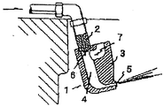
この種の従来の人体局部洗浄ノズルの断面図を図14に示す。同図において、本ノズル1は第1ノズル2およびノズル本体3より構成されている。
【0003】
このような構成の本ノズル1の第1ノズル2の上流に水圧を加えると、洗浄水は第1ノズル2より噴射され、ノズル本体3に設けられた空洞4を通り、途中で約90度水流の方向が曲げられて噴射口5より局部に向かって噴射される。この際、第1ノズル2の噴射口6付近には空気吸入口7が設けられているので、温水は空気を吸引し、気泡が混入された状態で噴射口より噴射される。
そのため、局部に衝突する洗浄水の面積が増大し、人体は、たっぷり感のある洗浄を味わうことができた。
【0004】
【発明が解決しようとする課題】
従来の構成の人体局部洗浄ノズルでは、確かに人体は、たっぷり感のある洗浄を味わうことができるものの、刺激感や洗浄の重みに欠けるのも、また事実であった。
【0005】
本発明は、かかる従来の課題を解決するもので、たっぷり感があり、しかも、刺激感や洗浄の重みもある洗浄となる人体局部洗浄ノズルおよびこれを備えた人体局部洗浄装置を提供することを目的としている。
【0006】
【課題を解決するための手段およびその作用・効果】
上記目的を達成するために請求項1の人体局部洗浄ノズルは、給水路を備え、人体局部に対して洗浄水を噴射する人体局部洗浄ノズルであって、前記給水路に形成され、出口を前記人体局部に指向させたオリフィス部と、前記オリフィス部の周囲に設けられた空気取入口と、前記オリフィス部の出口と前記人体局部とを結ぶ軌跡上に設けられたスロート部と、を有し、前記スロート部は、前記オリフィス部の出口から噴射された洗浄水に前記空気取入口から吸い込んだ空気を混合して、人体局部に人体が感知できないくらい速い周期でピーク荷重を発生させるとともに、前記スロート部は、その内周上に、前記洗浄水への空気混合効果を高め前記ピーク荷重を助長し、その周囲よりも径が小さくされた突起、段部あるいは凹凸形状を有し、前記スロート部の入口から出口までが前記オリフィス部と同一軸線上に配置されるとともに、前記出口が大気に開放されていることを特徴とする。
【0007】
従来の構成では、第1ノズル2より噴射された洗浄水は、ノズル本体3に設けられた空洞4を通り、途中で約90度水流の方向が曲げられる時に、エネルギーを損失(すなわち洗浄水が減速)する。
しかし、請求項1に記載の人体局部洗浄ノズルによれば、オリフィス部の出口が人体局部を指向しており、オリフィス部の上流に水圧を加えると、オリフィス部の出口から噴射される洗浄水は、何らの障害を受けずに噴射された水圧で人体局部に衝突する。つまり、エネルギーの損失(すなわち洗浄水の減速)がない。したがって、人体は刺激感のある洗浄を味わうことができる。
【0008】
また、オリフィス部の周囲には空気取入口が設けられており、オリフィス部の出口から洗浄水が噴射されると、オリフィス部の周囲が負圧になるため、空気が吸い込まれる(いわゆる、エジェクタ効果)。このエジェクタ効果により吸い込まれた空気は、オリフィス部の出口から噴射される洗浄水の表面を乱し、スロート部から噴射される洗浄水を、その乱れ具合により細くしたり太くしたりする。この洗浄水の細太の繰り返しは、スロート部から噴射される洗浄水の高速と低速の繰り返しを生じさせ、その速度差の繰り返しによって洗浄水の噴流の疎密の繰り返しが自然的変動として現れる。
【0009】
このような疎密を繰り返す洗浄水は、特に密の部分で人体にたっぷり感を与える。しかも、その疎密の繰り返しは人体が感知できないくらい速いので、あたかも人体は常に密の状態で洗浄水が衝突しているかのように感じる。
したがって、前述の刺激感のある洗浄とともに、人体は、たっぶり感のある洗浄も味わうことができる。
【0010】
また、スロート部には、オリフィス部の出口から噴射された洗浄水に前記空気取入口から吸い込んだ空気を混合して、人体局部に人体が感知できないくらい速い周期でピーク荷重を発生させる気液混合促進手段が設けられているため、その変動が更に助長されて洗浄感を高められることになる。
【0011】
気液混合促進手段は、具体的には例えば図3に示すようなスロート内周上に符号15aで示すような突起あるいは段部、凹凸形状を設けることで達成される。気液混合流はスロート部の凹凸形状を通過する際に圧縮・開放作用が働くことで、洗浄水への空気混合効果が高まり高い洗浄力・洗浄感を持つ流れになる。
【0012】
なお、従来のノズル構成の場合にはスロート部で約90度の水流屈曲があり、屈曲部分で気液混合水が圧縮・開放され得るが、屈曲部での衝突による流速低下を起こしていた。
本発明のノズル構成ではオリフィス部と人体局部との軌跡上にスロート部が設けられており、かつ気液混合流作用形状が設けられているので、流速の低下がなく、かつ空気混入効果の高い洗浄水が吐出できる。
【0013】
前記した突起,段部,凹凸形状はスロート部に一体で成形しても、別部品の嵌め込みでも良い。気液混合作用形状はスロート内周の凹凸以外でも良く、軸方向の内周形状変化であれば効果が出やすい。
【0015】
また、請求項1に記載の人体局部洗浄ノズルによれば、スロート部とオリフィス部とを同一軸上に配置させるため、組立および組立後の検査工程において同一の方向から作業することができ、製造面、検査面等において有利であり、量産性に優れる。
【0016】
請求項2は、請求項1に記載の人体局部洗浄ノズルにおいて、前記オリフィス部に給水される洗浄水を、前記軌跡を中心軸として旋回させる洗浄水旋回部を有することを特徴とする。
【0017】
請求項2に記載の人体局部洗浄ノズルによれば、洗浄水旋回部によって、給水された洗浄水が旋回する。その旋回した洗浄水はオリフィス部、スロート部を通過し、円錐状に拡散して噴射される。したがって、局部に衝突する洗浄水の面積が増大し、人体は、よりたっぷり感のある洗浄を味わうことができる。
【0018】
請求項3は、請求項1または2に記載の人体局部洗浄ノズルにおいて、前記空気取入口から取り込まれる空気量を可変する可変部を有することを特徴とする。
【0019】
請求項3に記載の人体局部洗浄ノズルによれば、可変部により、空気取り入れ口から取り込まれる空気量が可変する。取り込まれる空気量が可変すると、洗浄水は、その乱れ具合が大きくなり、疎密差が大きく現れる。したがって、人体は、より刺激感のある洗浄を味わうことができる。
【0020】
請求項4は、請求項3に記載の人体局部洗浄ノズルにおいて、前記可変部は、前記空気取入口から取り込まれる空気量を、所定周期で変動させることを特徴とする。
【0021】
請求項4に記載の人体局部洗浄ノズルによれば、可変部により、空気取入口から取り込まれる空気量が所定周期で変動するため、洗浄水の乱れが周期的に発生する。そのため、洗浄水の疎密が周期的となり、人体は刺激感のある洗浄を安定して味わうことができる。
【0022】
請求項5は、請求項1ないし4に記載の人体局部洗浄ノズルにおいて、前記オリフィス部を、前記軌跡を中心軸として回転させるオリフィス回転部を有することを特徴とする。
【0023】
請求項5に記載の人体局部洗浄ノズルによれば、オリフィス回転部により、オリフィス部を、軌跡を中心軸として回転させる。オリフィス部が軌跡を中心軸として回転すると、洗浄水は円錐状を描くように噴射される。したがって、局部に衝突する洗浄水の面積が増大し、人体は、よりたっぷり感のある洗浄を味わうことができる。
【0024】
請求項6は、請求項1ないし5に記載の人体局部洗浄ノズルにおいて、前記オリフィス部に給水される洗浄水の圧力を、所定周期で変動させる洗浄水圧力変動部を有することを特徴とする。
【0025】
請求項6に記載の人体局部洗浄ノズルによれば、洗浄水圧力変動部によりオリフィス部に給水される洗浄水の圧力が所定周期で変動する。そのため、噴射される洗浄水は、オリフィス部、スロート部での自然的変動に加え、洗浄水圧力変動部により強制的変動により乱される。したがって、人体は、より刺激感のある洗浄を味わうことができる。
【0026】
請求項7は、給水路を備え、人体局部に対して洗浄水を噴射する人体局部洗浄ノズルであって、前記給水路に形成され、出口を前記人体局部に指向させたオリフィス部と、共振室と、前記オリフィス部の出口と前記人体局部とを結ぶ軌跡上に設けられたスロート部と、を有することを特徴とする。
【0048】
【発明の実施の形態】
以下、本発明の実施の形態を添付図面に基づいて説明する。
【0049】
図1は、本発明の一実施の形態を示す人体局部洗浄ノズルの概略斜視図、図2は、人体局部洗浄ノズルの先端の断面図であり、8は洗浄水が給水される給水路、10は給水路8から給水された洗浄水がオリフィス部12(後述)へ進路を変更させるための給水室、12は洗浄水の流速を高めるためのオリフィス部、13は空気を吸引するための空気吸引部、13Aは空気吸引部13の先端が接続されたオリフィス部の周囲に設けられた空気取入口、15はスロート部、である。
ここで、オリフィス部12の径をφ1.3mm、スロート部15の径をφ2.3mm(すなわち、オリフィス部12の出口の断面積S1とスロート部15の断面積S2との面積比S2/S1は3.1程度)となるように設定している。
また、スロート部15は、オリフィス部12から肛門aまたはビデbに至る軌跡X、Y上に配置されている。なお、図2に示す実施例では、オリフィス部12とスロート部15とは同一軸上に配置されている。
【0050】
なお、スロート部15の内周には、図3に示すような突起15aが形成されている。
【0051】
図4(a)、(b)は、給水路8と給水室10との配置を説明するための説明図であり、図2における肛門aまたはビデbの方向から見たものである。
このうち、図4(a)は、給水路8が給水室10の中心に向かって接続されているため、給水路8から給水された洗浄水は、軌跡XもしくはYに沿ってオリフィス部12に向かう。
【0052】
一方、図4(b)は、給水路8が給水室10の中心から偏心して接続されている(つまり、給水路8と給水室10とが洗浄水旋回部を構成する)ため、給水路8から給水された洗浄水は、軌跡XもしくはYに対して旋回してオリフィス部12に向かう。その旋回した洗浄水はオリフィス部12、スロート部15を通過し、円錐状に拡がって噴射される。
したがって、局部に衝突する洗浄水の面積が増大し、人体は、よりたっぷり感のある洗浄を味わうことができる。
【0053】
図5は、図4(a)に示す実施例を試作し洗浄水を吐水させ、その吐水させた洗浄水を該試作品から60mm離して配置したデジタル式プッシュプルゲージ(アイコーエンジニアリング製)にて洗浄水の荷重(押し力)を500HZのサンプリング周期で約2秒測定したデータであり、横軸は時間(秒)、縦軸は洗浄水の荷重(mN)を示す。
【0054】
図5に示すように、試作したノズルから噴射させると、500mN以上でピーク(最大)荷重値をしめす洗浄水が発生することが確認された。また、十数Hzの周期でピークが発生することも確認された。これは、オリフィス部12周囲の空気取入口13Aで洗浄水に混入される空気の混入量が、前述した気液混合手段の作用によって速い周期で変化されるため、スロート部15から噴射される洗浄水の表面を乱して洗浄水径を大小変化させ、洗浄水の噴射速度を高低変化させることになる。この洗浄水噴射速度の差が速い周期で繰り返されることにより、洗浄水の噴流の粗密が変化するので、洗浄水のピーク荷重を速い周期で出現させることができる。
【0055】
図6は、オリフィス部12の断面積S1とスロート部15の断面積S2との面積比S2/S1と、噴出された洗浄水が局部に当たった時のピーク荷重との関係を示したものである。
ここで、面積比S2/S1=3.1程度で500mN以上のピーク荷重が実験的に確かめられている。
【0056】
以上の構成において、次に本実施形態の作用効果を説明する。
オリフィス部12の上流に水圧を加えると、オリフィス部12の出口から噴射される洗浄水(流速12m/s程度)は、何らの障害を受けずに噴射された水圧で人体局部に衝突する。つまり、エネルギーの損失(すなわち洗浄水の減速)がない。
したがって、人体は刺激感のある洗浄を味わうことができる。
【0057】
また、オリフィス部12の出口から洗浄水が噴射されると、オリフィス部12の周囲が負圧になるため、オリフィス部12の周囲に設けられた吸気取入口13Aから空気が吸い込まれる(いわゆる、エジェクタ効果)。このエジェクタ効果により吸い込まれた空気は、オリフィス部12の出口から噴射される洗浄水の表面を乱し、スロート部15から噴射される洗浄水を、その乱れ具合により細くしたり太くしたりする。この洗浄水の細太の繰り返しは、スロート部から噴射される洗浄水の高速と低速の繰り返しを生じさせ、その速度差の繰り返しは、洗浄水の噴流の疎密の繰り返しとして現れる。
このような疎密を繰り返す洗浄水は、特に密の部分で人体に、たっぷり感を与える。しかも、その疎密の繰り返しは人体が感知できないくらい速いので、あたかも人体は常に密の状態で洗浄水が衝突しているかのように感じる。
したがって、人体は、前述の刺激感のある洗浄とともに、たっぶり感のある洗浄を味わうことができる。
【0058】
図7は、図1の人体局部洗浄ノズルを備えた人体局部洗浄装置の水回路を示したものである。
水道源側(上流側)から、20は給水接続部、22は逆流防止のための逆止弁、24は給水された洗浄水中の異物を除去するストレーナ、26は給水圧の変動によらず下流を一定の圧力に保つ調圧弁、30は主流路電磁弁、32は胴体洗浄電磁弁、34は下流の圧力が上昇した場合にその圧力上昇を抑えるためのリリーフ弁、36は給水された洗浄水を加熱する1.1Lの貯湯が可能な貯湯式の熱交換器、38は真空破壊弁、40は流調弁(絞り弁)、42は切替弁、44は図1の人体局部洗浄ノズルを備えた伸縮自在なノズル本体(先端に図4(a)、(b)に示す実施例を各1つずつ備え、図4(a)を肛門洗浄用、図4(b)をビデ洗浄用として使用する)、46はノズル伸縮駆動モータである。
【0059】
なお、ここで、流調弁(絞り弁)40、切替弁42を説明のため、別々のブロックとしているが、一体で構成することも可能であり、以下の説明では一体として流調切替弁40、42として説明する。
この場合、流調切替弁40、42には、1つの流入路に対し3つの流出路を備えており、かつ内蔵する弁は、流入路と流出路の連通面積を回転角度により、選択的に可変かつ止水可能な構成としている。
また、弁はステッピングモータの駆動力により回転可能としている。
【0060】
図8は、ノズル本体44の伸縮状態を説明するための説明図である。
図8において、収納状態にあるノズル本体44を実線で示し、伸出状態にあるノズル本体44を破線で示す。
また、a、bはそれぞれ人体局部である肛門、ビデの洗浄位置であり、A、Bはそれぞれ肛門a、ビデbに対して洗浄水を噴射するためのノズル本体の伸出位置であり、X、Yはそれぞれオリフィス部と肛門a、ビデbとを結ぶ軌跡を示す。
【0061】
なお、図8において、矢印で示すように、伸出位置A、Bにおいてノズル本体44を微少ストロークで往復移動させることにより、局部の洗浄範囲を拡大できると同時に、局部に衝突する洗浄水の位置が変更することによって刺激感のある洗浄を味わうことができる。
【0062】
なお、ノズル本体44の微少ストロークでの往復移動の周期は、任意に設定・変更可能であり、噴射される洗浄水は、オリフィス部、スロート部によって疎密が繰り返される自然的変動に加え、ノズル本体44の往復移動により強制的変動により乱される。
したがって、人体は、より刺激感のある洗浄を味わうことができる。
【0063】
以上の構成において、人体に対して洗浄水を噴射するまでに人体局部洗浄装置の水回路を構成する部位の動作を図9に示すタイミングチャートを用いて説明する。
【0064】
まず、待機状態では、着座SW(着座スイッチ)、脱臭、洗浄SW(洗浄スイッチ)、主流路電磁弁30、胴体洗浄電磁弁32はOFF状態(非動作状態)にあり、ノズル本体44は収納状態、流調切替弁40、42は、流入路と3つの流出路が全て連通された位置(=SC)にある。
【0065】
待機状態において、人体が便座(図示しない)に着座すると、着座SW(着座スイッチ)がON状態になり、人体局部洗浄機能のインターロックが解除されると同時に脱臭機能(図示しない)がON状態(動作状態)となる。
次に、肛門への洗浄水の噴射要求としてのおしりスイッチ(図示しない)が操作されると、主流路電磁弁30がON状態(水路開放状態)となり、収納状態にあるノズル本体44から洗浄水が噴射される。この噴射された洗浄水は対面に配設された反射板45に反射し、ノズル本体44を洗浄する(=前洗浄)。
前洗浄後、熱交換器38に籠もった圧力を開放する(=圧抜き)。
圧抜き後、流調切替弁40、42は止水位置に移動し(=流調移動)する。
流調移動後、ノズル本体44が伸出するが、その際に胴体洗浄電磁弁32がON状態(水路開放状態)となり伸出中のノズル本体44の表面を洗浄する(=伸出(胴体洗浄))。
【0066】
伸出(胴体洗浄)後、実際の人体局部の洗浄するため、主流路電磁弁30をON状態とし、流調切替弁40、42による水路開放を徐々に進行させる(=ソフトスタート)。
ソフトスタート後、人体の好みの水勢による局部洗浄をする(=本洗浄)。
なお、噴射される洗浄水の水勢は、流調切替弁40、42により強弱が変更可能になっているが、最強(最大流量)が1L/min以下となるよう設計されている。そのため、人体局部洗浄ノズルからは、60秒以上温水を連続的に噴射することができる。
【0067】
洗浄水の止水要求としての止スイッチ(図示しない)が操作されると、主流路電磁弁30がOFF状態(水路閉鎖状態)となり、洗浄水の噴射が停止するが、その際、ノズル本体44、流調切替弁40、42はそのままの状態を保持し、熱交換器36に籠もった圧力を開放させる(=圧抜き)。
圧抜き後、流調切替弁40、42を止水位置に移動させる(=流調移動)。
流調移動完了後、ノズル本体44を収納位置へ収納すると同時に胴体洗浄電磁弁32をON状態とし、ノズル本体44の表面を洗浄する(=収納(胴体洗浄))。
【0068】
収納(胴体洗浄)後、流調切替弁40、42をSC位置に移動させ、主流路電磁弁30がON状態(水路開放状態)となり、収納状態にあるノズル本体44から洗浄水が噴射される。この噴射された洗浄水は対面に配設された反射板45に反射し、ノズル本体44を洗浄する(=後洗浄)。
【0069】
後洗浄後、流調切替弁40、42を原点位置に移動させ(=原点合わせ)、さらに、流調切替弁40、42をSC位置に移動させる(=流調移動)。
ここで、人が離座すると、着座SW(着座スイッチ)がOFF状態となり、脱臭機能が停止するのである。
【0070】
図10は、請求項3、4に対応する実施例であり、空気吸引部13から取り込まれる空気量を可変する可変部18を備えたものである。前述した実施例と同じ構成については、図に同じ符号を付している。また、スロート部15の内周には、図3に示すような突起15aが形成されている。この可変部18は、モータを備え、このモータにより高速(50HZ程度が望ましい)で空気吸引部13を開閉し、空気吸引部13から取り込まれる空気量を可変制御している。
【0071】
この実施例によれば、可変部18が開閉駆動することにより、空気吸引部13から取り込まれる空気量が可変する。取り込まれる空気量が可変すると、洗浄水は、その乱れ具合が大きくなり、疎密差が大きく現れる。
したがって、人体は、より刺激感のある洗浄を味わうことができる。
【0072】
なお、可変部18による空気量の可変周期は、任意に設定・変更可能であり、噴射される洗浄水は、オリフィス部、スロート部での自然的変動に加え、可変部18により強制的変動により乱される。
したがって、人体は、より刺激感のある洗浄を味わうことができる。
【0073】
図11は、請求項5に対応する実施例であり、オリフィス部12を、軌跡XもしくはYを中心軸として回転させるオリフィス回転部19を備えたものである。前述した実施例と同じ構成については、図に同じ符号を付している。また、スロート部15の内周には、図3に示すような突起15aが形成されている。このオリフィス回転部19は、モータを備え、このモータにより軌跡を中心軸としてノズルヘッドを回転させ、軌跡上に配設されたオリフィス部12の出口を、軌跡を中心軸として回転させるものである。
【0074】
この実施例によれば、オリフィス回転部19により、オリフィス部12を、軌跡XもしくはYを中心軸として回転させる。オリフィス部12が軌跡を中心軸として回転すると、そこから吐水される洗浄水は円錐状に拡がって噴射される。
したがって、局部に衝突する洗浄水の面積が増大し、人体は、よりたっぷり感のある洗浄を味わうことができる。
【0075】
なお、オリフィス回転部19によるオリフィス部12の回転周期は、任意に設定・変更可能であり、噴射される洗浄水は、オリフィス部、スロート部での自然的変動に加え、オリフィス回転部19により強制的変動により乱される。
したがって、人体は、より刺激感のある洗浄を味わうことができる。
【0076】
図12は、請求項6に対応する実施例であり、オリフィス部12に給水される洗浄水の圧力を、所定周期で変動をさせる洗浄水圧力変動部48を備えたものである。前述した実施例と同じ構成については、図に同じ符号を付している。また、スロート部15の内周には、図3に示すような突起15aが形成されている。この洗浄水圧力変動部48は、電磁コイルとプランジャーによって構成される公知のプランジャーポンプを備え、このプランジャーポンプの駆動により洗浄水に高い圧力が周期的に加えられるのである。
【0077】
この実施例によれば、洗浄水圧力変動部48により、オリフィス部12に給水される洗浄水の圧力が所定周期で変動する。そのため、噴射される洗浄水は、オリフィス部、スロート部での自然的変動に加え、洗浄水圧力変動部48により強制的変動により乱される。
したがって、人体は、より刺激感のある洗浄を味わうことができる。
【0078】
図13は、前述の実施例とは別の実施例であって、特に、共振室60を備えたものである。前述した実施例と同じ構成については、図に同じ符号を付している。
【0079】
この実施例によれば、共振室60が設けられており、オリフィス部12の出口から洗浄水が噴射されると、オリフィス部12の周囲(つまり共振室60)が負圧になる。この共振室60が負圧になると、スロート部15から噴射される洗浄水を該共振室60側に引っ張る力として作用し、結果として洗浄水は円錐状に拡がって吐水される。
そして、共振室60の負圧力が大きくなると、スロート部15の出口付近の大気が該共振室60に引き込まれるようになる。大気が共振室60に引き込まれると、該共振室が正圧になり、オリフィス部12から噴射された洗浄水は円錐状に拡がることなく、まとまった細い直線状の噴流となって吐水される。
このように、共振室60を設けることにより、円錐状の吐水と直線状の吐水が繰り返し行われる(いわゆる自己発振現象が起こる)。このような吐水が局部に衝突した場合、人体は円錐状の吐水の時には、たっぷり感を、直線状の吐水の時には刺激感のある洗浄を味わうことができるのである。
【図面の簡単な説明】
【図1】 本発明の一実施の形態を示す人体局部洗浄装置のノズル部
【図2】 人体局部洗浄装置のノズル部先端の断面図
【図3】 ノズルの気液混合促進手段を説明する、スロート部の模式的な断面図
【図4】 (a)は、給水路8が給水室10の中心に向かって接続されている図、(b)は、給水路8が給水室10の中心から偏心して接続されている(つまり、給水路8と給水室10とが洗浄水旋回部を構成する)図
【図5】 図4(a)に示す実施例を実際に試作し、洗浄水を吐水させた際の荷重を測定したデータ
【図6】 オリフィス部の出口の断面積S1とスロート部の断面積S2との面積比S2/S1と、噴出された洗浄水が局部に当たった時のピーク荷重との関係
【図7】 図1の人体局部洗浄ノズルを備えた人体局部洗浄装置の水回路
【図8】 ノズル本体44の伸縮状態を説明するための説明図
【図9】 人体局部洗浄装置の水回路を構成する部位の動作を示すタイミングチャート
【図10】 請求項3、4に対応する実施例
【図11】 請求項5に対応する実施例
【図12】 請求項6に対応する実施例
【図13】 共振室を備えた別の実施例
【図14】 従来の人体局部洗浄ノズルの断面図
【符号の説明】
1…本ノズル、2…第1ノズル、3…ノズル本体、4…空洞、5…噴射口、6…噴射口、7…空気吸入口、8…給水路、12…オリフィス部、13…空気吸引部、13A…空気取入口、15…スロート部、15a…突起(気液混合促進手段)、18…可変部、19…オリフィス回転部、20…給水接続部、22…逆止弁、24…ストレーナ、26…調圧弁、30…主流路電磁弁、32…胴体洗浄電磁弁、34…リリーフ弁、36…熱交換器、38…真空破壊弁、40…流調弁(絞り弁)、42…切替弁、44…ノズル本体、45…反射板、46…ノズル伸縮駆動モータ、48…洗浄水圧力変動部、60…共振室[0001]
BACKGROUND OF THE INVENTION
The present invention relates to a human body local cleaning nozzle used in a sanitary cleaning device or the like for cleaning a human body local part and a human body local cleaning apparatus including the same.
[0002]
[Prior art]
A human body local washing nozzle disclosed in Japanese Patent Publication No. 58-9688 is conventionally known.
A cross-sectional view of this type of conventional human body local cleaning nozzle is shown in FIG. In this figure, the
[0003]
When water pressure is applied to the upstream side of the
Therefore, the area of the washing water that collides with the local area increased, and the human body was able to enjoy a clean feeling.
[0004]
[Problems to be solved by the invention]
In the human body local cleaning nozzle having the conventional configuration, it is true that the human body can taste a lot of cleaning, but lacks the irritation and the weight of cleaning.
[0005]
The present invention solves such a conventional problem, and provides a human body local cleaning nozzle that has a lot of feeling and also has a feeling of irritation and a weight of cleaning, and a human body local cleaning device including the same. It is aimed.
[0006]
[Means for solving the problems and their functions and effects]
In order to achieve the above object, the human body local cleaning nozzle according to
[0007]
In the conventional configuration, the washing water sprayed from the
However, according to the human body local cleaning nozzle according to
[0008]
In addition, an air intake is provided around the orifice, and when washing water is injected from the outlet of the orifice, the pressure around the orifice becomes negative, so that air is sucked in (so-called ejector effect) ). The air sucked by the ejector effect disturbs the surface of the cleaning water ejected from the outlet of the orifice portion, and makes the cleaning water ejected from the throat portion thinner or thicker depending on the degree of the disturbance. The repetition of the thinness of the washing water causes a repetition of the high and low speeds of the washing water sprayed from the throat portion, and the repetition of the density difference of the washing water appears as a natural variation due to the repetition of the speed difference.
[0009]
Washing water that repeats such sparseness and denseness gives the human body plenty of feeling, especially in dense areas. Moreover, the repetition of the density is so fast that the human body cannot perceive it, so that the human body always feels as if the washing water collides in a dense state.
Therefore, in addition to the above-described cleaning with a sense of irritation, the human body can also enjoy the cleaning with a full feeling.
[0010]
In addition, the throat part mixes the air sucked from the air intake with the washing water jetted from the outlet of the orifice part, and the gas-liquid mixing generates a peak load at a cycle that is too fast for the human body to detect the human body. Promotion Since the means is provided, the fluctuation is further promoted and the cleaning feeling is enhanced.
[0011]
Gas-liquid mixing Promotion Specifically, for example, the means can be achieved by providing a projection or a stepped portion and a concavo-convex shape as indicated by reference numeral 15a on the inner periphery of the throat as shown in FIG. The gas-liquid mixed flow is compressed and released when it passes through the concavo-convex shape of the throat portion, so that the air mixing effect to the cleaning water is enhanced and the flow has a high cleaning power and feeling.
[0012]
In the case of the conventional nozzle configuration, the water flow bends at about 90 degrees at the throat portion, and the gas-liquid mixed water can be compressed and released at the bend portion, but the flow velocity is reduced due to the collision at the bend portion.
In the nozzle configuration of the present invention, the throat portion is provided on the trajectory between the orifice portion and the human body local portion, and the gas-liquid mixed flow action shape is provided, so there is no reduction in the flow velocity and high air mixing effect. Wash water can be discharged.
[0013]
The above-described protrusions, stepped portions, and concavo-convex shapes may be formed integrally with the throat portion or may be fitted with separate parts. The gas-liquid mixing action shape may be other than the irregularities on the inner circumference of the throat, and an effect is easily obtained if the inner circumference shape changes in the axial direction.
[0015]
Also,
[0016]
[0017]
[0018]
[0019]
[0020]
Claim 4
[0021]
Claim 4 According to the human body local cleaning nozzle described in 1), since the amount of air taken in from the air intake port fluctuates in a predetermined cycle by the variable unit, the cleaning water is periodically disturbed. Therefore, the density of the washing water becomes periodic, and the human body can stably enjoy the irritating washing.
[0022]
[0023]
[0024]
Claim 6
[0025]
Claim 6 According to the human body local cleaning nozzle described in (1), the pressure of the cleaning water supplied to the orifice portion by the cleaning water pressure fluctuation unit varies in a predetermined cycle. Therefore, the wash water to be jetted is disturbed by the forced fluctuation by the washing water pressure fluctuation part in addition to the natural fluctuation in the orifice part and the throat part. Therefore, the human body can taste more irritating cleaning.
[0026]
[0048]
DETAILED DESCRIPTION OF THE INVENTION
Hereinafter, embodiments of the present invention will be described with reference to the accompanying drawings.
[0049]
FIG. 1 is a schematic perspective view of a human body local cleaning nozzle showing an embodiment of the present invention, FIG. 2 is a cross-sectional view of the tip of the human body local cleaning nozzle, and 8 is a water supply channel for supplying cleaning water. Is a water supply chamber for changing the course of cleaning water supplied from the
Here, the diameter of the
The
[0050]
Note that a protrusion 15 a as shown in FIG. 3 is formed on the inner periphery of the
[0051]
4A and 4B are explanatory diagrams for explaining the arrangement of the
4A, since the
[0052]
On the other hand, in FIG. 4B, the
Therefore, the area of the washing water that collides with the local area increases, and the human body can enjoy a more comfortable washing.
[0053]
FIG. 5 is a digital push-pull gauge (manufactured by Aiko Engineering Co., Ltd.) in which the embodiment shown in FIG. 4 (a) is prototyped and the cleaning water is discharged, and the discharged cleaning water is disposed 60 mm away from the prototype. This is data obtained by measuring the load (pushing force) of washing water for about 2 seconds at a sampling period of 500 HZ. The horizontal axis represents time (seconds) and the vertical axis represents the washing water load (mN).
[0054]
As shown in FIG. 5, it was confirmed that when sprayed from a prototype nozzle, washing water having a peak (maximum) load value of 500 mN or more was generated. It was also confirmed that a peak occurred with a period of several tens of Hz. This is because the amount of air mixed into the cleaning water at the
[0055]
FIG. 6 shows the relationship between the area ratio S2 / S1 between the cross-sectional area S1 of the
Here, a peak load of 500 mN or more has been experimentally confirmed at an area ratio of S2 / S1 = 3.1.
[0056]
Next, the function and effect of this embodiment will be described.
When water pressure is applied upstream of the
Therefore, the human body can taste cleaning with a sense of irritation.
[0057]
Further, when cleaning water is jetted from the outlet of the
Washing water that repeats such sparseness and denseness gives the human body plenty of feeling, especially in dense areas. Moreover, the repetition of the density is so fast that the human body cannot perceive it, so that the human body always feels as if the washing water collides in a dense state.
Therefore, the human body can enjoy the washing with a feeling of fullness in addition to the washing with the above-mentioned irritation.
[0058]
FIG. 7 shows a water circuit of the human body local cleaning device including the human body local cleaning nozzle of FIG.
From the water supply side (upstream side), 20 is a water supply connection part, 22 is a check valve for preventing backflow, 24 is a strainer that removes foreign matter in the supplied wash water, and 26 is downstream regardless of fluctuations in the water supply pressure. Is a pressure regulating valve that maintains a constant pressure, 30 is a main flow path solenoid valve, 32 is a fuselage washing solenoid valve, 34 is a relief valve for suppressing the pressure rise when the downstream pressure rises, and 36 is supplied
[0059]
Here, the flow control valve (throttle valve) 40 and the switching
In this case, the flow
The valve is rotatable by the driving force of the stepping motor.
[0060]
FIG. 8 is an explanatory diagram for explaining the stretched state of the
In FIG. 8, the
Further, a and b are the washing positions of the anus and the bidet, which are local parts of the human body, respectively, A and B are the extending positions of the nozzle body for injecting washing water to the anus a and the bidet b, respectively. , Y indicate the trajectory connecting the orifice part to the anus a and the bidet b, respectively.
[0061]
In FIG. 8, as indicated by arrows, the cleaning range of the local area can be expanded by reciprocating the nozzle
[0062]
The cycle of the reciprocating movement of the
Therefore, the human body can taste more irritating cleaning.
[0063]
In the above configuration, the operation of the parts constituting the water circuit of the human body local cleaning device before the cleaning water is jetted onto the human body will be described with reference to the timing chart shown in FIG.
[0064]
First, in the standby state, the seating SW (seat switch), deodorization, cleaning SW (cleaning switch), the main flow
[0065]
When the human body is seated on the toilet seat (not shown) in the standby state, the seating SW (seat switch) is turned on, and the deodorizing function (not shown) is turned on at the same time the interlock of the human body local washing function is released. Operation state).
Next, when a butt switch (not shown) as a request for injecting wash water into the anus is operated, the main flow
After pre-cleaning, the pressure accumulated in the
After depressurization, the
After the flow adjustment, the
[0066]
After extension (body cleaning), in order to clean the actual human body part, the main flow
After the soft start, perform local cleaning with the water of your choice (= main cleaning).
In addition, although the strength of the water flow of the washing water to be injected can be changed by the flow
[0067]
When a stop switch (not shown) serving as a stop request for the wash water is operated, the main flow
After depressurization, the flow
After completion of the flow adjustment, the nozzle
[0068]
After storage (body cleaning), the flow
[0069]
After the post-cleaning, the flow
Here, when the person leaves, the seating SW (seat switch) is turned off, and the deodorizing function is stopped.
[0070]
FIG. 10
[0071]
According to this embodiment, the amount of air taken in from the
Therefore, the human body can taste more irritating cleaning.
[0072]
In addition, the variable period of the air amount by the
Therefore, the human body can taste more irritating cleaning.
[0073]
FIG. 11
[0074]
According to this embodiment, the
Therefore, the area of the washing water that collides with the local area increases, and the human body can enjoy a more comfortable washing.
[0075]
The rotation period of the
Therefore, the human body can taste more irritating cleaning.
[0076]
FIG. 12 claims 6 In this embodiment, the pressure of the cleaning water supplied to the
[0077]
According to this embodiment, the pressure of the cleaning water supplied to the
Therefore, the human body can taste more irritating cleaning.
[0078]
FIG. An embodiment different from the previous embodiment, In particular, a
[0079]
According to this embodiment, the
When the negative pressure in the
Thus, by providing the
[Brief description of the drawings]
FIG. 1 shows a nozzle part of a human body local cleaning device according to an embodiment of the present invention.
FIG. 2 is a cross-sectional view of the tip of a nozzle part of a local body cleaning device
[Figure 3] Gas-liquid mixing of the nozzle Promotion Schematic cross-sectional view of the throat, explaining the means
4A is a diagram in which the
FIG. 5 shows data obtained by actually making a prototype of the embodiment shown in FIG. 4A and measuring the load when the cleaning water is discharged.
FIG. 6 shows the relationship between the area ratio S2 / S1 between the cross-sectional area S1 at the outlet of the orifice part and the cross-sectional area S2 at the throat part, and the peak load when the sprayed cleaning water hits the local area.
7 is a water circuit of a human body local cleaning device including the human body local cleaning nozzle of FIG.
FIG. 8 is an explanatory diagram for explaining the expansion and contraction state of the
FIG. 9 is a timing chart showing the operation of the parts constituting the water circuit of the human body local cleaning device
FIG. 10
FIG. 11
FIG. 12 Claim 6 Examples corresponding to
FIG. 13 Another with a resonant chamber Example
FIG. 14 is a cross-sectional view of a conventional human body local cleaning nozzle
[Explanation of symbols]
DESCRIPTION OF
Claims (7)
前記給水路に形成され、出口を前記人体局部に指向させたオリフィス部と、
前記オリフィス部の周囲に設けられた空気取入口と、
前記オリフィス部の出口と前記人体局部とを結ぶ軌跡上に設けられたスロート部と、
を有し、
前記スロート部は、前記オリフィス部の出口から噴射された洗浄水に前記空気取入口から吸い込んだ空気を混合して、人体局部に人体が感知できないくらい速い周期でピーク荷重を発生させるとともに、
前記スロート部は、その内周上に、前記洗浄水への空気混合効果を高め前記ピーク荷重を助長し、その周囲よりも径が小さくされた突起、段部あるいは凹凸形状を有し、
前記スロート部の入口から出口までが前記オリフィス部と同一軸線上に配置されるとともに、前記出口が大気に開放されていることを特徴とする人体局部洗浄ノズル。 A human body local cleaning nozzle that has a water supply channel and injects cleaning water to the human body local part,
An orifice part formed in the water supply channel and having an outlet directed to the human body local part;
And an air inlet provided around the orifice,
A throat portion provided on a trajectory connecting the outlet of the orifice portion and the local body portion;
Have
The throat, a mixture of air sucked from the air inlet to the washing water injected from the outlet of the orifice portion, Rutotomoni to generate peak load at short intervals about no appreciable human on the human private,
The throat portion has, on its inner periphery, a projection, stepped portion or uneven shape whose diameter is smaller than its surroundings, enhancing the air mixing effect to the washing water and promoting the peak load,
The human body local washing nozzle , wherein the inlet to the outlet of the throat portion are arranged on the same axis as the orifice portion, and the outlet is open to the atmosphere .
前記オリフィス部に給水される洗浄水を、前記軌跡を中心軸として旋回させる洗浄水旋回部を有することを特徴とする人体局部洗浄ノズル。 In the human body local cleaning nozzle according to claim 1 ,
A human body local cleaning nozzle, comprising: a cleaning water swirling section that swirls cleaning water supplied to the orifice section around the locus as a central axis.
前記空気取入口から取り込まれる空気量を可変する可変部を有することを特徴とする人体局部洗浄ノズル。 In the human body local washing nozzle according to claim 1 or 2 ,
A human body local washing nozzle comprising a variable portion that varies the amount of air taken in from the air intake.
前記可変部は、前記空気取入口から取り込まれる空気量を、所定周期で変動させることを特徴とする人体局部洗浄ノズル。 In the human body local cleaning nozzle according to claim 3 ,
The human body local washing nozzle, wherein the variable section varies the amount of air taken in from the air intake at a predetermined cycle.
前記オリフィス部を、前記軌跡を中心軸として回転させるオリフィス回転部を有することを特徴とする人体局部洗浄ノズル。 In the human body local washing nozzle according to any one of claims 1 to 4 ,
A human body local cleaning nozzle, comprising: an orifice rotating section that rotates the orifice section about the locus as a central axis.
前記オリフィス部に給水される洗浄水の圧力を、所定周期で変動させる洗浄水圧力変動部を有することを特徴とする人体局部洗浄ノズル。 The human body local cleaning nozzle according to any one of claims 1 to 5 ,
A human body local cleaning nozzle, comprising: a cleaning water pressure fluctuation part that fluctuates the pressure of the washing water supplied to the orifice part at a predetermined cycle.
Priority Applications (1)
| Application Number | Priority Date | Filing Date | Title |
|---|---|---|---|
| JP2001272419A JP4984363B2 (en) | 2000-09-07 | 2001-09-07 | Human body local cleaning nozzle and human body local cleaning apparatus provided with the same |
Applications Claiming Priority (4)
| Application Number | Priority Date | Filing Date | Title |
|---|---|---|---|
| JP2000271035 | 2000-09-07 | ||
| JP2000271035 | 2000-09-07 | ||
| JP2000-271035 | 2000-09-07 | ||
| JP2001272419A JP4984363B2 (en) | 2000-09-07 | 2001-09-07 | Human body local cleaning nozzle and human body local cleaning apparatus provided with the same |
Publications (3)
| Publication Number | Publication Date |
|---|---|
| JP2002155567A JP2002155567A (en) | 2002-05-31 |
| JP2002155567A5 JP2002155567A5 (en) | 2008-10-16 |
| JP4984363B2 true JP4984363B2 (en) | 2012-07-25 |
Family
ID=26599408
Family Applications (1)
| Application Number | Title | Priority Date | Filing Date |
|---|---|---|---|
| JP2001272419A Expired - Fee Related JP4984363B2 (en) | 2000-09-07 | 2001-09-07 | Human body local cleaning nozzle and human body local cleaning apparatus provided with the same |
Country Status (1)
| Country | Link |
|---|---|
| JP (1) | JP4984363B2 (en) |
Families Citing this family (8)
| Publication number | Priority date | Publication date | Assignee | Title |
|---|---|---|---|---|
| KR20040001801A (en) * | 2002-06-28 | 2004-01-07 | 웅진코웨이개발 주식회사 | A injection nozzle for the bidet |
| KR100867861B1 (en) * | 2007-07-02 | 2008-11-07 | 웅진코웨이주식회사 | Nozzle tip |
| EP2397614B1 (en) | 2009-02-12 | 2016-09-07 | Toto Ltd. | Hygiene cleaning device |
| JP5633267B2 (en) | 2009-09-30 | 2014-12-03 | Toto株式会社 | Sanitary washing device |
| JP4572999B1 (en) * | 2010-01-15 | 2010-11-04 | Toto株式会社 | Sanitary washing device |
| JP5569778B2 (en) | 2010-02-09 | 2014-08-13 | Toto株式会社 | Sanitary washing device |
| CN102900136B (en) * | 2011-07-27 | 2014-08-13 | Toto株式会社 | Water discharge device |
| KR101583046B1 (en) * | 2014-02-10 | 2016-01-06 | 대한중천산업 주식회사 | nozzle tip assembly for a bidet |
Family Cites Families (5)
| Publication number | Priority date | Publication date | Assignee | Title |
|---|---|---|---|---|
| JPS6091672U (en) * | 1983-11-24 | 1985-06-22 | 株式会社ノーリツ | Nozzle for hot water flushing toilet flushing fountain |
| JP2566310B2 (en) * | 1989-02-15 | 1996-12-25 | 松下電工株式会社 | Local cleaning device |
| JP2906937B2 (en) * | 1993-09-06 | 1999-06-21 | 松下電器産業株式会社 | Sanitary washing equipment |
| JP2000008453A (en) * | 1998-04-20 | 2000-01-11 | Toto Ltd | Human body washing equipment |
| JPH11350570A (en) * | 1998-06-11 | 1999-12-21 | Toto Ltd | Nozzle for washing private part |
-
2001
- 2001-09-07 JP JP2001272419A patent/JP4984363B2/en not_active Expired - Fee Related
Also Published As
| Publication number | Publication date |
|---|---|
| JP2002155567A (en) | 2002-05-31 |
Similar Documents
| Publication | Publication Date | Title |
|---|---|---|
| KR101775394B1 (en) | Sanitary cleaning apparatus | |
| JP6718591B2 (en) | Sanitary washing equipment | |
| KR0152683B1 (en) | Sanitary cleaning apparatus | |
| JP4984363B2 (en) | Human body local cleaning nozzle and human body local cleaning apparatus provided with the same | |
| JP6718590B2 (en) | Sanitary washing equipment | |
| TWI634253B (en) | Sanitary washing device | |
| JP2002167844A (en) | Washing nozzle for human body private parts and washing device for human body private parts provided with same | |
| JP2002188202A (en) | Method and device for washing human-body private part | |
| JP2002194798A (en) | Private part washing nozzle and the private parts washing equipment therewith for human body | |
| JP4631174B2 (en) | Local cleaning equipment | |
| JP4622065B2 (en) | Human body local cleaning equipment | |
| JP4721025B2 (en) | Cleaning device | |
| JP2002088873A (en) | Private part washing nozzle for human body, and private part of human body washing device provided with the same | |
| JP4492259B2 (en) | Fluid ejection device and sanitary washing toilet seat using the same | |
| JP2867831B2 (en) | Sanitary washing equipment | |
| JPH06257203A (en) | Sanitary washing nozzle and sanitary mashing device | |
| JP2017179710A (en) | Sanitary washing device | |
| JP6751508B2 (en) | Sanitary washing equipment | |
| JP6718592B2 (en) | Sanitary washing equipment | |
| JP3900900B2 (en) | Cleaning toilet seat with drying function | |
| JP2003147839A (en) | Flushing closet seat having drying function | |
| JP3211571B2 (en) | Sanitary washing equipment | |
| JP2017179707A (en) | Sanitary washing device | |
| KR20220076655A (en) | Bidet cleaning nozzle for air in | |
| JP2017179706A (en) | Sanitary washing device |
Legal Events
| Date | Code | Title | Description |
|---|---|---|---|
| A521 | Written amendment |
Free format text: JAPANESE INTERMEDIATE CODE: A523 Effective date: 20080903 |
|
| A621 | Written request for application examination |
Free format text: JAPANESE INTERMEDIATE CODE: A621 Effective date: 20080903 |
|
| A977 | Report on retrieval |
Free format text: JAPANESE INTERMEDIATE CODE: A971007 Effective date: 20110114 |
|
| A131 | Notification of reasons for refusal |
Free format text: JAPANESE INTERMEDIATE CODE: A131 Effective date: 20110124 |
|
| A131 | Notification of reasons for refusal |
Free format text: JAPANESE INTERMEDIATE CODE: A131 Effective date: 20110929 |
|
| TRDD | Decision of grant or rejection written | ||
| A01 | Written decision to grant a patent or to grant a registration (utility model) |
Free format text: JAPANESE INTERMEDIATE CODE: A01 Effective date: 20120403 |
|
| A01 | Written decision to grant a patent or to grant a registration (utility model) |
Free format text: JAPANESE INTERMEDIATE CODE: A01 |
|
| A61 | First payment of annual fees (during grant procedure) |
Free format text: JAPANESE INTERMEDIATE CODE: A61 Effective date: 20120416 |
|
| R150 | Certificate of patent or registration of utility model |
Ref document number: 4984363 Country of ref document: JP Free format text: JAPANESE INTERMEDIATE CODE: R150 Free format text: JAPANESE INTERMEDIATE CODE: R150 |
|
| FPAY | Renewal fee payment (event date is renewal date of database) |
Free format text: PAYMENT UNTIL: 20150511 Year of fee payment: 3 |
|
| LAPS | Cancellation because of no payment of annual fees |