JP4983926B2 - Optical communication apparatus and optical communication method - Google Patents
Optical communication apparatus and optical communication method Download PDFInfo
- Publication number
- JP4983926B2 JP4983926B2 JP2009535915A JP2009535915A JP4983926B2 JP 4983926 B2 JP4983926 B2 JP 4983926B2 JP 2009535915 A JP2009535915 A JP 2009535915A JP 2009535915 A JP2009535915 A JP 2009535915A JP 4983926 B2 JP4983926 B2 JP 4983926B2
- Authority
- JP
- Japan
- Prior art keywords
- signal
- dispersion
- optical
- optical communication
- amount
- Prior art date
- Legal status (The legal status is an assumption and is not a legal conclusion. Google has not performed a legal analysis and makes no representation as to the accuracy of the status listed.)
- Expired - Fee Related
Links
Images


Classifications
-
- H—ELECTRICITY
- H04—ELECTRIC COMMUNICATION TECHNIQUE
- H04B—TRANSMISSION
- H04B10/00—Transmission systems employing electromagnetic waves other than radio-waves, e.g. infrared, visible or ultraviolet light, or employing corpuscular radiation, e.g. quantum communication
- H04B10/25—Arrangements specific to fibre transmission
- H04B10/2507—Arrangements specific to fibre transmission for the reduction or elimination of distortion or dispersion
- H04B10/2513—Arrangements specific to fibre transmission for the reduction or elimination of distortion or dispersion due to chromatic dispersion
- H04B10/25133—Arrangements specific to fibre transmission for the reduction or elimination of distortion or dispersion due to chromatic dispersion including a lumped electrical or optical dispersion compensator
-
- H—ELECTRICITY
- H04—ELECTRIC COMMUNICATION TECHNIQUE
- H04B—TRANSMISSION
- H04B10/00—Transmission systems employing electromagnetic waves other than radio-waves, e.g. infrared, visible or ultraviolet light, or employing corpuscular radiation, e.g. quantum communication
- H04B10/60—Receivers
- H04B10/66—Non-coherent receivers, e.g. using direct detection
- H04B10/69—Electrical arrangements in the receiver
- H04B10/697—Arrangements for reducing noise and distortion
- H04B10/6971—Arrangements for reducing noise and distortion using equalisation
Description
この発明は、受信した光信号を分散補償する光通信装置および光通信方法に関する。 The present invention relates to an optical communication apparatus and an optical communication method for compensating dispersion of a received optical signal.
近年、大容量伝送用ネットワークとして光ネットワークが用いられている。光ネットワークの方式の一つにPON(Passive Optical Network)方式がある。PON方式は、複数の加入者側端末(ONU:Optical Network Unit)からバースト的に送信された光信号をスターカプラで合波し、一つの収容局側端末(OLT:Optical Line Terminal)で受信する方式である。 In recent years, optical networks have been used as large-capacity transmission networks. One of optical network systems is a PON (Passive Optical Network) system. In the PON system, optical signals transmitted in bursts from a plurality of subscriber side terminals (ONU: Optical Network Unit) are combined by a star coupler, and received by one accommodating station side terminal (OLT: Optical Line Terminal). It is a method.
PON方式のさらなる高速化や、super PONなどの伝送距離の長距離化を視野に入れた場合は、伝送路の分散による光信号の劣化の補償が必要となる。PON方式においては、OLTと各ONUとの間の伝送路の距離に応じて、各ONUから送信されてOLTが受信する各光信号の分散量がそれぞれ異なる。このため、OLTは、受信した光信号毎に異なる補償量によって分散補償を行う必要がある。 In view of further increasing the speed of the PON system and increasing the transmission distance such as super PON, it is necessary to compensate for optical signal degradation due to dispersion of the transmission path. In the PON system, the amount of dispersion of each optical signal transmitted from each ONU and received by the OLT differs depending on the distance of the transmission path between the OLT and each ONU. For this reason, the OLT needs to perform dispersion compensation with a different compensation amount for each received optical signal.
一方、受信した光信号の波形を測定し、測定した波形に基づいて、受信した光信号の波形を補償する技術が開示されている(たとえば、下記特許文献1〜3参照。)。このような技術を用いて、PON方式において、受信した各光信号の波形に基づいて各光信号の分散量を算出し、算出した分散量によって分散補償を行うことが考えられる。
On the other hand, a technique for measuring the waveform of a received optical signal and compensating the waveform of the received optical signal based on the measured waveform is disclosed (for example, see
しかしながら、各ONUから送信される光信号のパターンはランダムであるため、光信号の分散量は光信号の波形の歪みと一意的に対応しない。このため、上述した従来技術では、光信号の波形を測定することで光信号の分散量を算出することが困難であるという問題がある。以下、この問題について詳細に説明する。 However, since the pattern of the optical signal transmitted from each ONU is random, the dispersion amount of the optical signal does not uniquely correspond to the distortion of the waveform of the optical signal. For this reason, the above-described conventional technique has a problem that it is difficult to calculate the dispersion amount of the optical signal by measuring the waveform of the optical signal. Hereinafter, this problem will be described in detail.
図20は、分散があるバースト信号のアイパターンを示す図である。バースト的に送信された光信号(バースト信号)の分散による波形の歪みは、光信号のパターンによって異なる。このため、図20に示すように、分散がある光信号のアイパターン(たとえばアイパターンのクロスポイント2010)は一意に定まらない。したがって、光信号全体の波形の歪みを一意的に測定することができず、光信号の波形を測定することで光信号の分散量を精度よく算出することが困難である。
FIG. 20 is a diagram illustrating an eye pattern of a burst signal with dispersion. Waveform distortion due to dispersion of optical signals (burst signals) transmitted in bursts varies depending on the pattern of the optical signals. For this reason, as shown in FIG. 20, the eye pattern of an optical signal with dispersion (for example, the
また、光信号全体の波形の平均的な歪みを測定することも考えられるが、光信号の大部分を受信した後に平均的な波形を算出する必要があるため、光信号の分散量を算出するまでに時間がかかるという問題がある。このため、たとえば、各ONUから順次受信する光信号毎に分散量を算出して分散補償を行うことができないという問題がある。 Although it is conceivable to measure the average distortion of the waveform of the entire optical signal, it is necessary to calculate the average waveform after receiving most of the optical signal, so the amount of dispersion of the optical signal is calculated. There is a problem that it takes time until. For this reason, for example, there is a problem that dispersion compensation cannot be performed by calculating the dispersion amount for each optical signal sequentially received from each ONU.
開示の光通信装置および光通信方法は、上述した問題点を解消するものであり、光信号を精度よく高速に分散補償することを目的とする。 The disclosed optical communication apparatus and optical communication method solve the above-described problems, and an object thereof is to perform dispersion compensation of an optical signal with high accuracy and at high speed.
光通信装置が、光送信装置から送信される光信号を受信する受信手段と、前記受信手段によって受信される信号が含む固定パターン信号を検出する検出手段と、前記検出手段によって検出される固定パターン信号の波形に基づいて前記固定パターン信号の分散量を算出する算出手段と、前記算出手段によって算出される分散量に応じて前記信号を分散補償する補償手段と、を備える。 An optical communication apparatus receives an optical signal transmitted from the optical transmission apparatus, a detection means for detecting a fixed pattern signal included in a signal received by the reception means, and a fixed pattern detected by the detection means Calculation means for calculating a dispersion amount of the fixed pattern signal based on a waveform of the signal, and compensation means for dispersion-compensating the signal according to the dispersion amount calculated by the calculation means.
光信号に含まれる固定パターン信号の波形の歪みは光信号の分散量と一意的に対応するため、上記構成によれば、固定パターン信号の波形に基づいて分散量を算出することで光信号の分散量を精度よく高速に算出することができる。 Since the distortion of the waveform of the fixed pattern signal included in the optical signal uniquely corresponds to the amount of dispersion of the optical signal, according to the above configuration, the amount of dispersion of the optical signal can be calculated by calculating the amount of dispersion based on the waveform of the fixed pattern signal. The amount of dispersion can be calculated accurately and at high speed.
開示の光通信装置および光通信方法によれば、光信号を精度よく高速に分散補償することができるという効果を奏する。 According to the disclosed optical communication apparatus and optical communication method, there is an effect that dispersion compensation of an optical signal can be performed with high accuracy and at high speed.
100 光通信装置
110 PD
140 分散モニタ部
143 平均検出部
145a 遅延部
145b 遅延部
145 区間設定部
200 光信号
210 プリアンブル信号
220 データ信号
420 検出信号
430,440 トリガー信号
540,1320 振幅
550 パルス幅
1600,1900 ネットワーク
1610,1910 スターカプラ100
140
以下に添付図面を参照して、この発明にかかる光通信装置および光通信方法の好適な実施の形態を詳細に説明する。 Exemplary embodiments of an optical communication device and an optical communication method according to the present invention will be explained below in detail with reference to the accompanying drawings.
(実施の形態1)
図1は、実施の形態1にかかる光通信装置の構成を示すブロック図である。図1に示すように、実施の形態1にかかる光通信装置100は、PD110と、TIA120と、LIA130と、分散モニタ部140と、電気分散補償器150と、を備えている。PD110は、外部から送信された光信号を受信する受信手段である。PD110は、受信した光信号を電気的な信号に変換してTIA120および分散モニタ部140へ出力する。(Embodiment 1)
FIG. 1 is a block diagram of a configuration of the optical communication apparatus according to the first embodiment. As illustrated in FIG. 1, the
TIA120(インピーダンス変換増幅器:TransImpedance Amplifier)およびLIA130(制限増幅器:LImiting Amplifier)は、PD110から出力された信号を一定振幅に増幅する増幅手段である。TIA120およびLIA130は、一定振幅に増幅した信号を電気分散補償器150へ出力する。
TIA 120 (impedance conversion amplifier) and LIA 130 (limiting amplifier) are amplification means for amplifying the signal output from
分散モニタ部140は、ピーク検出部141と、ボトム検出部142と、平均検出部143と、プリアンブル検出部144と、区間設定部145と、強度比算出部146と、サンプルホールド部147と、を備えている。ピーク検出部141は、PD110から出力された信号のピークパワーを検出する。ピーク検出部141は、検出したピークパワーの情報をプリアンブル検出部144および強度比算出部146へ出力する。
The
ボトム検出部142は、PD110から出力された信号のボトムパワーを検出する。ボトム検出部142は、検出したボトムパワーの情報をプリアンブル検出部144および強度比算出部146へ出力する。平均検出部143は、PD110から出力された信号の平均パワーを検出する。ここでは、平均検出部143は、並列に接続されたコンデンサ143aおよび抵抗143bによって構成されるローパスフィルタである。平均検出部143は、検出した平均パワーの情報を強度比算出部146へ出力する。
The
プリアンブル検出部144は、ピーク検出部141およびボトム検出部142から出力された情報に基づいて、PD110によって受信された信号のピーク部分とボトム部分を判定することで、PD110によって受信された信号に含まれるプリアンブル信号を検出する検出手段である。プリアンブル検出部144は、プリアンブル信号を検出すると、プリアンブル信号を検出した旨の検出信号を区間設定部145へ出力する。
The
区間設定部145は、プリアンブル信号のうちの分散量を測定する区間を設定する設定手段である。具体的には、区間設定部145は、遅延部145a(delay1)と、遅延部145b(delay2)と、を備えている。遅延部145aは、プリアンブル検出部144から検出信号が出力されると、所定の時間delay1だけ遅延して第1のトリガー信号を強度比算出部146および遅延部145bへ出力する。
The
遅延部145bは、遅延部145aから第1のトリガー信号が出力されると、所定の時間delay2だけ遅延して第2トリガー信号を強度比算出部146へ出力する。区間設定部145へ第1のトリガー信号が出力されてから第2のトリガー信号が出力されるまでに受信されるプリアンブル信号の区間が、分散量を測定する測定区間として設定される。
When the first trigger signal is output from the
強度比算出部146は、プリアンブル検出部144によって検出されたプリアンブル信号の分散量を算出する算出手段である。また、強度比算出部146は、プリアンブル信号のうちの、区間設定部145によって設定された区間の分散量を算出する。以下、強度比算出部146によるプリアンブル信号の分散量の算出について具体的に説明する。
The intensity
強度比算出部146は、区間設定部145から第1のトリガー信号が出力されてから第2のトリガー信号が出力されるまでの期間に、ピーク検出部141から出力された情報が示す信号のピークパワーと、ボトム検出部142から出力された情報が示すボトムパワーと、の差を算出することで、PD110から出力された信号の振幅の情報を取得する。
The intensity
また、強度比算出部146は、区間設定部145から第1のトリガー信号が出力されてから第2のトリガー信号が出力されるまでの期間に、平均検出部143から出力される平均パワーの情報を取得する。そして、強度比算出部146は、取得した振幅および平均パワーの情報に基づいて、プリアンブル信号の振幅および平均パワーの強度比を算出する。
In addition, the intensity
強度比算出部146は、算出した強度比の情報をプリアンブル信号の分散量の情報としてサンプルホールド部147へ出力する。サンプルホールド部147は、強度比算出部146から出力された情報が示す分散量に応じて電気分散補償器150の補償量を設定する。電気分散補償器150は、サンプルホールド部147によって設定された補償量によって、TIA120およびLIA130から出力された信号を分散補償する。
The intensity
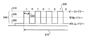
図2は、光通信装置が受信する光信号の構成を示す図である。図2に示すように、光通信装置100が受信する光信号200は、プリアンブル信号210と、データ信号220と、を含むバースト信号である。プリアンブル信号210は、光信号200の先頭に格納されたあらかじめパターンが定められた固定パターン信号である。強度比算出部146は、プリアンブル信号210の分散量を算出する。
FIG. 2 is a diagram illustrating a configuration of an optical signal received by the optical communication apparatus. As shown in FIG. 2, the
ここでは、プリアンブル信号210は、「101010…」の交番信号である。データ信号220は、伝送されるデータが格納された信号であり、プリアンブル信号210よりも後に受信される。なお、プリアンブル信号210の分散量を算出する場合について説明したが、分散量を算出する信号はプリアンブル信号210に限らず、あらかじめパターンが定められた固定パターン信号であり、データ信号220よりも先に受信されればよい。
Here, the
図3は、実施の形態1にかかる光通信装置の動作を示すフローチャートである。ここでは、光通信装置100が1つの光信号(バースト信号)に対して行う分散補償動作について説明する。図3に示すように、まず、PD110が、外部から送信された光信号を受信する(ステップS301)。つぎに、ピーク検出部141およびボトム検出部142が、それぞれ信号のピークパワーおよびボトムパワーを検出する(ステップS302)。
FIG. 3 is a flowchart of the operation of the optical communication apparatus according to the first embodiment. Here, a dispersion compensation operation performed by the
つぎに、プリアンブル検出部144が、プリアンブル信号を検出したか否かを判断する(ステップS303)。プリアンブル信号を検出していない場合(ステップS303:No)は、ステップS302に戻って処理を続行する。プリアンブル信号を検出した場合(ステップS303:Yes)は、区間設定部145が、プリアンブル信号における分散量の測定区間を設定する(ステップS304)。
Next, the
つぎに、強度比算出部146が、ステップS304によって設定されたプリアンブル信号の区間の振幅および平均パワーの情報を取得する(ステップS305)。つぎに、強度比算出部146が、ステップS305によって取得した情報に基づいて、PD110から出力された信号の振幅と平均パワーとの強度比を算出する(ステップS306)。
Next, the intensity
つぎに、電気分散補償器150が、ステップS306によって算出された強度比に基づいて分散補償を行い(ステップS307)、1つの光信号に対する一連の分散補償動作を終了する。同様に、順次受信する光信号に対してもステップS301〜ステップS307の動作をそれぞれ行うことで、各光信号を個別に分散補償することができる。
Next, the
図4は、実施の形態1にかかる光通信装置の動作のタイムチャートを示す図である。図4において、図2に示した部分と同様の部分については同一の符号を付して説明を省略する。図4において、横軸は時間を示している。縦軸は各信号の強度を示している。符号410は、PD110が受信した信号(図2参照)を示している。信号410は、プリアンブル信号210およびデータ信号220を含んでいる。
FIG. 4 is a time chart of the operation of the optical communication apparatus according to the first embodiment. In FIG. 4, the same parts as those shown in FIG. In FIG. 4, the horizontal axis represents time. The vertical axis represents the intensity of each signal.
符号420(Preamble detect)は、プリアンブル検出部144から区間設定部145へ出力される検出信号を示している。検出信号420は、プリアンブル信号210がPD110によって受信されると区間設定部145へ出力される。符号430(Trigger1)は、遅延部145aから強度比算出部146へ出力される第1のトリガー信号を示している。
Reference numeral 420 (Preamble detect) indicates a detection signal output from the
第1のトリガー信号430は、検出信号420に対して所定の時間delay1だけ遅延して強度比算出部146へ出力される。符号440(Trigger2)は、遅延部145bから強度比算出部146へ出力される第2のトリガー信号を示している。第2のトリガー信号440は、第1のトリガー信号430に対して所定の時間delay2だけ遅延して強度比算出部146へ出力される。
The
区間450は、信号410のうちの強度比算出部146が分散量を算出する区間を示している。具体的には、区間450は、強度比算出部146へ第1のトリガー信号430が出力されてから、強度比算出部146へ第2のトリガー信号440が出力されるまでの期間に、PD110によって受信された信号410の区間である。
A
TIA120およびLIA130による信号の増幅と、強度比算出部146による信号の分散量の算出と、は並行して行われる。このため、電気分散補償器150は、PD110によって受信された信号410のうちの、強度比算出部146によって分散量が算出される区間450よりも後ろの区間を分散補償することになる。
The signal amplification by the
強度比算出部146によって分散量を算出される区間450は、遅延部145aのdelay1と遅延部145bのdelay2の設定により調節することができる。強度比算出部146によって分散量を算出される区間450がプリアンブル信号210の一部または全部となるようにdelay1およびdelay2を設定することで、プリアンブル信号210を受信している間に信号410全体の分散量を算出することができる。
The
これにより、データ信号220を受信する前に信号410の分散量を算出することができる。このため、算出した分散量に応じた補償量によって、信号410のうちの少なくともデータ信号220を分散補償することができる。なお、強度比算出部146によって分散量を算出する区間450は、図4に示したようにプリアンブル信号210の一部の区間であってもよいし、プリアンブル信号210の全ての区間であってもよい。
Thereby, the dispersion amount of the
ここでは、プリアンブル信号210が「101010…」の交番信号であるため、少なくとも、プリアンブル信号210の最初の2ビット(「10」)の部分に区間450を設定することで、プリアンブル信号210のピークパワー、ボトムパワーおよび平均パワーを検出することができる。このため、プリアンブル信号210の少なくとも最初の2ビットの波形を測定するだけで光信号200の分散量を算出することができる。
Here, since the
図5は、分散量が小さい場合のプリアンブル信号の波形を示す図である。図6は、分散量が大きい場合のプリアンブル信号の波形を示す図である。図5および図6において、図2に示した部分と同様の部分については同一の符号を付して説明を省略する。符号510,符号520および符号530は、プリアンブル信号210のピークパワー,ボトムパワーおよび平均パワーをそれぞれ示している。
FIG. 5 is a diagram illustrating a waveform of a preamble signal when the amount of dispersion is small. FIG. 6 is a diagram illustrating a waveform of a preamble signal when the amount of dispersion is large. 5 and 6, the same parts as those shown in FIG. 2 are denoted by the same reference numerals and description thereof is omitted.
符号540は、プリアンブル信号210の振幅を示している。振幅540は、ピークパワー510からボトムパワー520までの幅である。符号550は、プリアンブル信号210のパルス幅を示している。図5および図6に示すように、光信号200の分散量が大きい場合(図6)は、光信号200の分散量が小さい場合(図5)に比べて、プリアンブル信号210のパルス幅550が小さくなる。
このため、光信号200の分散量が大きい場合は、光信号200の分散量が小さい場合に比べて平均パワー530が低くなる。したがって、プリアンブル信号210の振幅540と平均パワー530との強度比は、光信号200の分散量に応じて変化する。このため、強度比算出部146は、プリアンブル信号210の振幅540と平均パワー530との強度比を算出することで、光信号200の分散量の情報を取得することができる。
For this reason, when the dispersion amount of the
図7は、分散がない交番信号をシミュレーションした波形図である。図8は、分散量が小さい交番信号をシミュレーションした波形図である。図9は、分散量が大きい交番信号をシミュレーションした波形図である。図7〜図9において、横軸は時間を示している。縦軸は、「101010…」の交番信号の強度を示している。縦軸のVthは、交番信号のピークパワーおよびボトムパワーの中央値を示している。図7〜図9に示すように、交番信号のパルス幅は、分散量が大きくなるほど小さくなることが分かる。 FIG. 7 is a waveform diagram simulating an alternating signal having no dispersion. FIG. 8 is a waveform diagram simulating an alternating signal with a small dispersion amount. FIG. 9 is a waveform diagram simulating an alternating signal having a large dispersion amount. 7 to 9, the horizontal axis represents time. The vertical axis indicates the intensity of the alternating signal “101010...”. Vth on the vertical axis indicates the median value of the peak power and bottom power of the alternating signal. As shown in FIGS. 7 to 9, it can be seen that the pulse width of the alternating signal becomes smaller as the dispersion amount becomes larger.
図10は、図7〜図9に示した交番信号のアイパターンを示す図である。図10において、横軸は時間(bit period)を示している。縦軸は振幅(a.u.)を示している。図10に示すように、「101010…」の交番信号のアイパターン(たとえばアイパターンのクロスポイント1010)は一意的に定まっていることが分かる。
FIG. 10 is a diagram showing an eye pattern of the alternating signal shown in FIGS. In FIG. 10, the horizontal axis represents time (bit period). The vertical axis represents the amplitude (au). As shown in FIG. 10, it can be seen that the eye pattern of the alternating signal “101010...” (For example, the
このため、交番信号の分散量を精度よく算出することができる。また、交番信号の一部のみの波形を測定するだけで分散量を精度よく算出することができる。たとえば、「101010…」の交番信号のうちの2ビット(「10」)の波形を測定するだけで分散量を精度よく算出することができる。このため、分散量を高速に算出することができる。 For this reason, the dispersion amount of the alternating signal can be calculated with high accuracy. Also, the dispersion amount can be calculated with high accuracy by measuring only a part of the waveform of the alternating signal. For example, the amount of dispersion can be calculated with high accuracy simply by measuring the 2-bit (“10”) waveform of the alternating signal “101010...”. For this reason, the amount of dispersion can be calculated at high speed.
このように、実施の形態1にかかる光通信装置100によれば、光信号200のプリアンブル信号210の波形に基づいて分散量を算出することで、光信号200の分散量を精度よく高速に算出することができる。このため、プリアンブル信号210の波形に基づいて算出した分散量に基づいて光信号200のデータ信号220を分散補償することで、データ信号220を精度よく高速に分散補償することができる。
As described above, according to the
また、光信号の分散量を精度よく高速に算出することができるため、分散量が不明な光信号を受信した場合にも、適切な補償量によって分散補償を行うことができる。これにより、たとえばPONなどにおいて、光通信装置100が複数の光送信装置からそれぞれ分散量の異なる光信号を順次受信する場合に、受信する光信号毎に分散量を算出して各光信号を個別に分散補償することが可能になる。
In addition, since the dispersion amount of the optical signal can be calculated with high accuracy and at high speed, dispersion compensation can be performed with an appropriate compensation amount even when an optical signal with an unknown dispersion amount is received. Thus, for example, in PON, when the
(実施の形態2)
図11は、実施の形態2にかかる光通信装置の構成を示すブロック図である。図11において、図1に示した構成と同様の構成については同一の符号を付して説明を省略する。図11に示すように、実施の形態2にかかる光通信装置100は、実施の形態1に示した光通信装置100の構成(図1参照)において、ピーク検出部141およびボトム検出部142を省いた構成である。(Embodiment 2)
FIG. 11 is a block diagram of a configuration of the optical communication apparatus according to the second embodiment. In FIG. 11, the same components as those shown in FIG. As illustrated in FIG. 11, the
PD110は、受信した光信号を電気的な信号に変換してTIA120へ出力する。TIA120およびLIA130は、増幅した信号を電気分散補償器150および分散モニタ部140へ出力する。分散モニタ部140の平均検出部143は、TIA120およびLIA130から出力された信号の平均パワーを検出する。
The
プリアンブル検出部144は、TIA120およびLIA130から出力された信号のピーク部分とボトム部分を判定することで、あらかじめ定められた固定パターンのプリアンブル信号を検出する。強度比算出部146は、区間設定部145から第1のトリガー信号が出力されてから第2のトリガー信号が出力されるまでの期間にPD110から出力される信号の平均パワーの情報を取得する。
The
具体的には、強度比算出部146は、区間設定部145から第1のトリガー信号が出力されてから第2のトリガー信号が出力されるまでの期間に平均検出部143から出力される平均パワーの情報を取得する。強度比算出部146は、取得した平均パワーと、TIA120およびLIA130に設定された振幅と、の強度比を算出する。強度比算出部146は、算出した強度比の情報を、PD110から出力された信号に含まれるプリアンブル信号の分散量の情報としてサンプルホールド部147へ出力する。
Specifically, the intensity
図12は、実施の形態2にかかる光通信装置の動作を示すフローチャートである。ここでは、光通信装置100が1つの光信号(バースト信号)に対して行う分散補償動作について説明する。図12に示すように、まず、PD110が、外部から送信された光信号を受信する(ステップS1201)。つぎに、TIA120およびLIA130が、ステップS1201によって受信された信号を一定振幅に増幅する(ステップS1202)。
FIG. 12 is a flowchart of the operation of the optical communication apparatus according to the second embodiment. Here, a dispersion compensation operation performed by the
つぎに、プリアンブル検出部144が、プリアンブル信号を検出したか否かを判断する(ステップS1203)。プリアンブル信号を検出していない場合(ステップS1203:No)は、ステップS1203に戻って処理を続行する。プリアンブル信号を検出した場合(ステップS1203:Yes)は、区間設定部145が、プリアンブル信号における分散量の測定区間を設定する(ステップS1204)。
Next, the
つぎに、強度比算出部146が、ステップS1204によって設定された測定区間の平均パワーの情報を取得する(ステップS1205)。つぎに、強度比算出部146が、ステップS1205によって取得した情報と、TIA120およびLIA130にあらかじめ定められた信号の振幅の情報と、に基づいて、PD110から出力された信号の振幅と平均パワーとの強度比を算出する(ステップS1206)。
Next, the intensity
つぎに、電気分散補償器150が、ステップS1206によって算出された強度比に基づいて分散補償を行い(ステップS1207)、1つの光信号に対する一連の分散補償動作を終了する。同様に、順次受信する各光信号に対しても、ステップS1201〜ステップS1207の動作を行うことで、各光信号を個別に分散補償することができる。
Next, the
図13は、実施の形態2にかかる光通信装置の動作のタイムチャートを示す図である。図13において、図4に示した部分と同様の部分については同一の符号を付して説明を省略する。符号1310は、TIA120およびLIA130によって一定振幅に増幅された信号を示している。符号1320は、あらかじめ定められた信号1310の振幅を示している。符号1330は、信号1310の平均パワーを示している。
FIG. 13 is a time chart of the operation of the optical communication apparatus according to the second embodiment. In FIG. 13, the same parts as those shown in FIG.
TIA120およびLIA130によって一定振幅に増幅された信号1310は、分散モニタ部140へ入力される。強度比算出部146は、平均検出部143から出力される情報が示す平均パワー1330と、あらかじめ定められた振幅1320と、の強度比を算出することで、プリアンブル信号210の分散量を算出することができる。
The
このように、実施の形態2にかかる光通信装置100によれば、実施の形態1にかかる光通信装置100の効果を奏するとともに、TIA120およびLIA130によって一定振幅に増幅されたプリアンブル信号の分散量を算出することで、強度比算出部146によって信号の振幅を算出することなくプリアンブル信号の分散量を算出することができる。このため、光信号の分散量をさらに高速に算出することができる。
As described above, according to the
(実施の形態3)
図14は、実施の形態3にかかる光通信装置の構成を示すブロック図である。図14において、図1に示した構成と同様の構成については同一の符号を付して説明を省略する。図14に示すように、実施の形態3にかかる光通信装置100は、図1に示した光通信装置100の構成において、電気分散補償器150に代えて光分散補償器1410を備えている。光分散補償器1410は、PD110の前段に設けられている。(Embodiment 3)
FIG. 14 is a block diagram of a configuration of the optical communication apparatus according to the third embodiment. In FIG. 14, the same components as those shown in FIG. As illustrated in FIG. 14, the
光分散補償器1410は、サンプルホールド部147によって設定された補償量によって、外部の光送信装置から送信された光信号を分散補償する。光分散補償器1410は、分散補償した光信号をPD110へ出力する。PD110は、光分散補償器1410から出力された光信号を受信する。サンプルホールド部147は、強度比算出部146から出力された情報が示す分散量に応じて光分散補償器1410の補償量を設定する。
The
このように、実施の形態3にかかる光通信装置100によれば、電気分散補償器150に代えて光分散補償器1410を用いて、PD110の前段で分散補償を行う場合にも、実施の形態1にかかる光通信装置100と同様に、プリアンブル信号の波形に基づいて分散量を算出することで、光信号の分散量を精度よく高速に算出することができる。
As described above, according to the
(実施の形態4)
図15は、実施の形態4にかかる光通信装置の構成を示すブロック図である。図15において、図11に示した構成と同様の構成については同一の符号を付して説明を省略する。図15に示すように、実施の形態4にかかる光通信装置100は、図11に示した光通信装置100の構成において、電気分散補償器150に代えて光分散補償器1510を備えている。光分散補償器1510は、PD110の前段に設けられている。(Embodiment 4)
FIG. 15 is a block diagram of a configuration of the optical communication apparatus according to the fourth embodiment. In FIG. 15, the same components as those shown in FIG. As illustrated in FIG. 15, the
光分散補償器1510は、サンプルホールド部147によって設定された補償量によって、外部の光送信装置から送信された光信号を分散補償する。光分散補償器1510は、分散補償した光信号をPD110へ出力する。PD110は、光分散補償器1510から出力された光信号を受信する。サンプルホールド部147は、強度比算出部146から出力された情報が示す分散量に応じて光分散補償器1510の補償量を設定する。
The
このように、実施の形態4にかかる光通信装置100によれば、電気分散補償器150に代えて光分散補償器1510を用いて、PD110の前段で分散補償を行う場合にも、実施の形態2にかかる光通信装置100と同様に、プリアンブル信号の波形に基づいて分散量を算出することで、光信号の分散量を精度よく高速に算出することができる。
As described above, according to the
図16は、光通信装置をPONに適用した実施例を示すブロック図である。上述した各実施の形態にかかる光通信装置100は、たとえば、図16に示すように、PON方式のネットワーク1600におけるOLTに適用することができる。PON方式のネットワーク1600は、OLTとしての光通信装置100と、複数のONU#1〜#nと、スターカプラ1610と、によって構成されている。
FIG. 16 is a block diagram showing an embodiment in which the optical communication apparatus is applied to the PON. The
光通信装置100は、スターカプラ1610を介して複数のONU#1〜#nとそれぞれ接続している。光通信装置100は、複数のONU#1〜#nが光通信装置100と通信を行うタイミングを管理し、通信を行うタイミングの情報を複数のONU#1〜#nへそれぞれ送信する。複数のONU#1〜#nは、光通信装置100から出力された情報が示すタイミングによって光通信装置100へ光信号を送信する。
The
図17は、実施例にかかる光通信装置が受信する各光信号の波形を示す図である。図17において、符号1701〜符号1707は、OLTとしての光通信装置100が受信する各光信号を示している。たとえば、光信号1701は、ONU#4から送信されて光通信装置100が受信した光信号である。光信号1702は、光信号1701のつぎに、ONU#5から送信されて光通信装置100が受信した光信号である。
FIG. 17 is a diagram illustrating waveforms of optical signals received by the optical communication apparatus according to the embodiment. In FIG. 17,
光信号1701〜光信号1707は、ONU#1〜#nのうちの光信号を送信したONUと光通信装置100との間の伝送路に応じてそれぞれ劣化する。このため、図17に示すように、光通信装置100が受信する各光信号はそれぞれ強度が異なる。また、図示しないが、光通信装置100が受信する各光信号の分散量もそれぞれ異なる。
The
図18は、実施例にかかる光通信装置が補償した信号の波形を示す図である。図18に示すように、光通信装置100は、光信号1701〜光信号1707を順次受信しながら一定振幅に増幅する。また、図示しないが、光通信装置100は、光信号1701〜光信号1707を順次受信しながら各信号に含まれるプリアンブル信号の分散量をそれぞれ算出し、算出した分散量によって各信号を個別に分散補償する。
FIG. 18 is a diagram illustrating a waveform of a signal compensated by the optical communication apparatus according to the example. As illustrated in FIG. 18, the
図19は、光通信装置をsuper PONに適用した実施例を示すブロック図である。図19において、図16に示した構成と同様の構成については同一の符号を付して説明を省略する。上述した各実施の形態にかかる光通信装置100は、たとえば、図19に示すように、super PON方式のネットワーク1900におけるOLTに適用することができる。
FIG. 19 is a block diagram showing an embodiment in which the optical communication apparatus is applied to the super PON. In FIG. 19, the same components as those shown in FIG. The
super PON方式のネットワーク1900は、図16に示したネットワーク1600の構成に加えてスターカプラ1910を設けることによって、さらに多くのONUが光通信装置100と接続されて構成されている。また、各伝送路上に光アンプ1921〜1923が設けられている。光アンプ1921〜1923は、光通信装置100と複数のONU#1〜#nとの間で送受信される各光信号を増幅する。
The
図16および図19に示したように、上述した各実施の形態にかかる光通信装置100は、PON方式のネットワークのOLTのように、複数の光送信装置から送信される各光信号を順次受信する光通信装置に適用することができる。これにより、順次受信する各光信号の分散量を精度よく高速に算出し、各光信号を個別に分散補償することができる。
As illustrated in FIGS. 16 and 19, the
なお、上述した各実施の形態にかかる光通信装置100は、分散補償器を備えて分散補償する構成として説明したが、強度比算出部146によって算出した光信号の分散量の情報を、光信号を送信する光送信装置にフィードバックする構成にしてもよい。分散量の情報をフィードバックされた光送信装置は、フィードバックされた情報が示す分散量の逆特性となる分散量を光信号に与えて送信する。これによって分散補償を行うことができる。
The
以上説明したように、開示の光通信装置および光通信方法によれば、光信号に含まれるプリアンブル信号の分散量を算出することで、光信号を精度よく高速に分散補償することができる。 As described above, according to the disclosed optical communication apparatus and optical communication method, it is possible to accurately perform high-speed dispersion compensation on an optical signal by calculating the amount of dispersion of the preamble signal included in the optical signal.
Claims (8)
前記受信手段によって受信される信号が含む固定パターン信号を検出する検出手段と、
前記検出手段によって検出される固定パターン信号の振幅および平均パワーの強度比に基づいて前記固定パターン信号の分散量を算出する算出手段と、
前記算出手段によって算出される分散量に応じて前記信号を分散補償する補償手段と、
を備えることを特徴とする光通信装置。Receiving means for receiving an optical signal transmitted from the optical transmitter;
Detecting means for detecting a fixed pattern signal included in the signal received by the receiving means;
Calculating means for calculating a dispersion amount of the fixed pattern signal based on an intensity ratio of the amplitude and average power of the fixed pattern signal detected by the detecting means;
Compensation means for compensating dispersion of the signal according to the amount of dispersion calculated by the calculation means;
An optical communication device comprising:
前記補償手段は、前記算出手段により算出される分散量に応じて、前記信号のうちの少なくとも前記データ信号を分散補償することを特徴とする請求項1に記載の光通信装置。The signal includes the fixed pattern signal received as a preamble signal and a data signal received after the fixed pattern signal,
The optical communication apparatus according to claim 1, wherein the compensation unit performs dispersion compensation on at least the data signal among the signals in accordance with a dispersion amount calculated by the calculation unit.
前記算出手段は、前記一定振幅と、前記増幅手段によって増幅された固定パターン信号の平均パワーと、の強度比に基づいて前記分散量を算出することを特徴とする請求項1に記載の光通信装置。2. The optical communication according to claim 1, wherein the calculation unit calculates the dispersion amount based on an intensity ratio between the constant amplitude and an average power of the fixed pattern signal amplified by the amplification unit. apparatus.
前記算出手段は、前記設定手段によって設定される区間の分散量を算出することを特徴とする請求項1に記載の光通信装置。The optical communication apparatus according to claim 1, wherein the calculation unit calculates a dispersion amount of a section set by the setting unit.
前記受信工程によって受信される信号が含む固定パターン信号を検出する検出工程と、A detection step of detecting a fixed pattern signal included in the signal received by the reception step;
前記検出工程によって検出される固定パターン信号の振幅および平均パワーの強度比に基づいて前記固定パターン信号の分散量を算出する算出工程と、A calculation step of calculating a dispersion amount of the fixed pattern signal based on an amplitude ratio of the fixed pattern signal detected by the detection step and an average power;
前記算出工程によって算出される分散量に応じて前記信号を分散補償する補償工程と、A compensation step for dispersion compensating the signal according to the dispersion amount calculated by the calculation step;
を含むことを特徴とする光通信方法。An optical communication method comprising:
Applications Claiming Priority (1)
| Application Number | Priority Date | Filing Date | Title |
|---|---|---|---|
| PCT/JP2007/069306 WO2009044457A1 (en) | 2007-10-02 | 2007-10-02 | Optical communication device and optical communication method |
Publications (2)
| Publication Number | Publication Date |
|---|---|
| JPWO2009044457A1 JPWO2009044457A1 (en) | 2011-02-03 |
| JP4983926B2 true JP4983926B2 (en) | 2012-07-25 |
Family
ID=40525890
Family Applications (1)
| Application Number | Title | Priority Date | Filing Date |
|---|---|---|---|
| JP2009535915A Expired - Fee Related JP4983926B2 (en) | 2007-10-02 | 2007-10-02 | Optical communication apparatus and optical communication method |
Country Status (3)
| Country | Link |
|---|---|
| US (1) | US8311418B2 (en) |
| JP (1) | JP4983926B2 (en) |
| WO (1) | WO2009044457A1 (en) |
Families Citing this family (4)
| Publication number | Priority date | Publication date | Assignee | Title |
|---|---|---|---|---|
| US9136813B2 (en) * | 2013-11-25 | 2015-09-15 | Texas Instruments Incorporated | Wireless network receiver |
| EP3132548B1 (en) * | 2014-04-15 | 2021-06-02 | ARRIS Enterprises LLC | Smart receivers and transmitters for catv networks |
| US9621972B2 (en) * | 2015-07-29 | 2017-04-11 | Rockley Photonics Limited | Burst-mode receiver |
| US10491299B2 (en) * | 2016-03-15 | 2019-11-26 | Oe Solutions America, Inc. | Electronic dispersion compensation methods and implementations using RLC filter synthesis |
Citations (2)
| Publication number | Priority date | Publication date | Assignee | Title |
|---|---|---|---|---|
| JPH1084317A (en) * | 1996-06-07 | 1998-03-31 | Northern Telecom Ltd | Optical fiber transmission system |
| JP2006304170A (en) * | 2005-04-25 | 2006-11-02 | Mitsubishi Electric Corp | Pon system and dispersion compensating method therefor |
Family Cites Families (5)
| Publication number | Priority date | Publication date | Assignee | Title |
|---|---|---|---|---|
| JPS62291232A (en) * | 1986-06-11 | 1987-12-18 | Ricoh Co Ltd | Data communicating system |
| US6252692B1 (en) * | 1996-06-07 | 2001-06-26 | Nortel Networks Limited | Optical fibre transmission systems |
| JPH11205245A (en) | 1998-01-13 | 1999-07-30 | Furukawa Electric Co Ltd:The | Optical transmission system |
| JP3895560B2 (en) | 2001-06-29 | 2007-03-22 | 富士通株式会社 | Method and apparatus for measuring waveform of optical signal |
| JP3526852B2 (en) | 2002-06-10 | 2004-05-17 | 沖電気工業株式会社 | Identification threshold setting circuit and DC level shift circuit |
-
2007
- 2007-10-02 JP JP2009535915A patent/JP4983926B2/en not_active Expired - Fee Related
- 2007-10-02 WO PCT/JP2007/069306 patent/WO2009044457A1/en active Application Filing
-
2010
- 2010-02-24 US US12/659,083 patent/US8311418B2/en not_active Expired - Fee Related
Patent Citations (2)
| Publication number | Priority date | Publication date | Assignee | Title |
|---|---|---|---|---|
| JPH1084317A (en) * | 1996-06-07 | 1998-03-31 | Northern Telecom Ltd | Optical fiber transmission system |
| JP2006304170A (en) * | 2005-04-25 | 2006-11-02 | Mitsubishi Electric Corp | Pon system and dispersion compensating method therefor |
Also Published As
| Publication number | Publication date |
|---|---|
| WO2009044457A1 (en) | 2009-04-09 |
| JPWO2009044457A1 (en) | 2011-02-03 |
| US8311418B2 (en) | 2012-11-13 |
| US20100158541A1 (en) | 2010-06-24 |
Similar Documents
| Publication | Publication Date | Title |
|---|---|---|
| JP4983926B2 (en) | Optical communication apparatus and optical communication method | |
| US8390798B2 (en) | Wavelength dispersion measurement method and device and optical transmission system | |
| US7324758B2 (en) | Optical dispersion monitoring apparatus and optical dispersion monitoring method, and optical transmission system using same | |
| RU2013119978A (en) | DEFINITION OF ASYMMETRIES IN A COMMUNICATION NETWORK | |
| WO2017215481A1 (en) | Optical power detection method, apparatus and device, and optical module | |
| EP2833567B1 (en) | Optical fiber testing method, apparatus and passive optical network system | |
| JP5811955B2 (en) | Burst signal receiving apparatus and method, PON station apparatus, PON system | |
| EP3758258B1 (en) | Measuring linear and non-linear transmission perturbations in optical transmission systems | |
| US20080212716A1 (en) | Burst mode receiver for passive optical network | |
| JP2013024650A (en) | Fiber measurement device | |
| US6421153B1 (en) | Device and method for determining PMD independent of SOP | |
| JP2014121009A (en) | Communication monitoring device, communication monitoring method and optical line test system | |
| JP2007173908A (en) | Burst optical signal receiver and gain setting method thereof | |
| US8989575B2 (en) | Signal detection method and optical signal receiving system | |
| US20040190912A1 (en) | Burst mode optical receiver | |
| US9838074B2 (en) | Crosstalk suppression method and apparatus | |
| JP2010141683A (en) | Optical transmission apparatus and dispersion compensator | |
| US11652544B2 (en) | Correlation optical time domain reflectometry method and system | |
| Borkowski et al. | In-service pre-ranging for upstream ONU activation in low-latency TDM-PON using downstream data only | |
| JP2003198467A (en) | Waveform distortion detector, system and method | |
| JP4671947B2 (en) | Eye monitor method, eye monitor circuit, optical receiving method, and optical receiver | |
| CN101444018A (en) | Signal quality detector | |
| JP4957567B2 (en) | Optical receiver | |
| US20100111528A1 (en) | Station device and optical communication system using same | |
| JP5189435B2 (en) | Optical pulse tester |
Legal Events
| Date | Code | Title | Description |
|---|---|---|---|
| A131 | Notification of reasons for refusal |
Free format text: JAPANESE INTERMEDIATE CODE: A131 Effective date: 20110816 |
|
| A521 | Written amendment |
Free format text: JAPANESE INTERMEDIATE CODE: A523 Effective date: 20111017 |
|
| TRDD | Decision of grant or rejection written | ||
| A01 | Written decision to grant a patent or to grant a registration (utility model) |
Free format text: JAPANESE INTERMEDIATE CODE: A01 Effective date: 20120327 |
|
| A01 | Written decision to grant a patent or to grant a registration (utility model) |
Free format text: JAPANESE INTERMEDIATE CODE: A01 |
|
| A61 | First payment of annual fees (during grant procedure) |
Free format text: JAPANESE INTERMEDIATE CODE: A61 Effective date: 20120409 |
|
| R150 | Certificate of patent or registration of utility model |
Free format text: JAPANESE INTERMEDIATE CODE: R150 |
|
| FPAY | Renewal fee payment (event date is renewal date of database) |
Free format text: PAYMENT UNTIL: 20150511 Year of fee payment: 3 |
|
| LAPS | Cancellation because of no payment of annual fees |