JP4983666B2 - Imaging device - Google Patents
Imaging device Download PDFInfo
- Publication number
- JP4983666B2 JP4983666B2 JP2008069051A JP2008069051A JP4983666B2 JP 4983666 B2 JP4983666 B2 JP 4983666B2 JP 2008069051 A JP2008069051 A JP 2008069051A JP 2008069051 A JP2008069051 A JP 2008069051A JP 4983666 B2 JP4983666 B2 JP 4983666B2
- Authority
- JP
- Japan
- Prior art keywords
- image data
- tracking area
- zoom
- zoom magnification
- setting
- Prior art date
- Legal status (The legal status is an assumption and is not a legal conclusion. Google has not performed a legal analysis and makes no representation as to the accuracy of the status listed.)
- Expired - Fee Related
Links
Images


Landscapes
- Studio Devices (AREA)
Description
本発明は、被写体に対する追尾機能を備える撮像装置に関する。例えば、追尾機能を備えるデジタルカメラ、ビデオカメラなどに適用可能である。 The present invention relates to an imaging apparatus having a tracking function for a subject. For example, the present invention can be applied to a digital camera or a video camera having a tracking function.
従来の撮像装置としては、下記の特許文献1に記載されるようなものが存在する。
As a conventional imaging device, there is one as described in
この撮像装置は、被写体像を形成する光学系と、光学系によって形成された被写体像を撮像して画像データを生成する撮像手段と、生成された画像データのうち追尾領域内の被写体像(追尾対象となる被写体)の特徴を抽出する抽出手段と、抽出された被写体像の特徴に基づいて、被写体像の相対的な移動を検出する検出手段と、当該検出された被写体像の相対的な移動に応じて、追尾領域を移動する追尾領域移動手段と、を備えるものである。
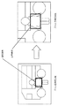
ところで、特許文献1に記載する撮像装置では、光学系のズーム倍率が変更された場合、追尾領域の大きさが一定であるため、図16のように追尾領域内の被写体像の特徴がズーム倍率変更前と変更後で大きく異なってしまう。図16は、左上の図がズーム倍率変更前の画像データ、左下の図が変更前における追尾領域内の色信号情報の分布、また、右上の図がズーム倍率変更後の画像データ、右下の図が変更後における追尾領域内の色信号情報の分布である。
By the way, in the imaging apparatus described in
このため、追尾領域内の被写体像の特徴を利用して、追尾領域を移動させようとしても、ズーム倍率変更後において、ズーム倍率変更前の被写体像の特徴と同様の特徴が得られず、追尾領域の相対的な移動を検出することができない。 For this reason, even if an attempt is made to move the tracking area using the characteristics of the subject image in the tracking area, the same characteristics as the characteristics of the subject image before the zoom magnification change cannot be obtained after the zoom magnification change. The relative movement of the region cannot be detected.
ここで、このような課題を解決する方法として、図17のように、光学系のズーム倍率が変更された場合に、このズーム倍率の変化量に応じて、追尾領域を拡大または縮小することが考えられる。 Here, as a method for solving such a problem, when the zoom magnification of the optical system is changed as shown in FIG. 17, the tracking area is enlarged or reduced according to the amount of change of the zoom magnification. Conceivable.
しかしながら、例えば、光学系のズーム倍率の変化量に応じて、追尾領域を拡大させた場合、図18で示すように、追尾領域の相対的な移動を検出するために行う検索動作の処理量が増加する。これは、追尾領域の拡大によって、追尾領域内の画素数が増えたからである。また、追尾領域内の画素数が増えたことによって、検索範囲となる領域も増えたからである。 However, for example, when the tracking area is enlarged according to the amount of change in the zoom magnification of the optical system, as shown in FIG. 18, the processing amount of the search operation performed to detect the relative movement of the tracking area is large. To increase. This is because the number of pixels in the tracking area has increased due to the expansion of the tracking area. This is also because the number of search areas increases as the number of pixels in the tracking area increases.
そこで本発明は、上記課題を解決するため、画像の倍率が変化した場合でも、より安定した追尾動作ができる撮像装置を提供することを目的とする。 Accordingly, an object of the present invention is to provide an imaging apparatus capable of performing a more stable tracking operation even when the magnification of an image is changed, in order to solve the above problems.
すなわち、本発明の撮像装置は、被写体像を形成する光学系と、前記形成された被写体像を撮像して画像データを生成する撮像手段と、前記光学系のズーム倍率を変更可能なズーム倍率変更手段と、前記撮像手段で生成された画像データを電子的に縮小又は拡大して、縮小又は拡大された画像データを生成する電子ズーム処理手段と、前記生成された画像データの一部を追尾領域として設定する設定手段と、追尾領域内の特徴に基づいて、前記撮像手段で順次生成される画像データ内において追尾領域を移動する追尾領域移動手段と、を備える。そして、前記設定手段で追尾領域を設定した後前記ズーム倍率変更手段で光学系のズーム倍率が変更されている場合、前記電子ズーム処理手段は、前記追尾領域の設定時のズーム倍率からの変化量に応じて縮小又は拡大された画像データを生成し、前記追尾領域移動手段は、前記電子ズーム処理手段で縮小又は拡大された画像データの中から前記追尾領域内の特徴を検索することにより、新たな位置に追尾領域を移動する。 That is, an imaging apparatus according to the present invention includes an optical system that forms a subject image, an imaging unit that captures the formed subject image and generates image data, and a zoom magnification change that can change a zoom magnification of the optical system. Means, electronic zoom processing means for electronically reducing or enlarging the image data generated by the imaging means to generate reduced or enlarged image data, and a tracking area for a part of the generated image data Setting means for setting as follows, and tracking area moving means for moving the tracking area in the image data sequentially generated by the imaging means based on the characteristics in the tracking area. When the zoom magnification of the optical system is changed by the zoom magnification changing means after the tracking area is set by the setting means, the electronic zoom processing means changes the amount of change from the zoom magnification when the tracking area is set. The tracking area moving means generates new image data by searching for characteristics in the tracking area from the image data reduced or enlarged by the electronic zoom processing means. Move the tracking area to the correct position.
このようにすれば、追尾領域設定時からズーム倍率を変更した場合であっても、撮像手段から生成された画像データを縮小するようにしたので、検索するために用いられる追尾領域の大きさを大きく変更する必要がなくなる。そのため、追尾領域の移動先を検索するための処理を、追尾領域設定時であるズーム倍率変更前と、ズーム倍率変更後で同程度にすることができる。なお、同程度とは、ズーム倍率変更前とズーム倍率変更後で処理量を同じにすることではない。 In this way, even when the zoom magnification is changed from the time of setting the tracking area, the image data generated from the imaging means is reduced, so the size of the tracking area used for the search is reduced. There is no need to make major changes. Therefore, the processing for searching for the movement destination of the tracking area can be made the same level before the zoom magnification change when the tracking area is set and after the zoom magnification change. Note that the same level does not mean that the processing amount is the same before the zoom magnification is changed and after the zoom magnification is changed.
また、好ましくは、前記設定手段で追尾領域を設定した後前記ズーム倍率変更手段で光学系のズーム倍率が変更されている場合の電子ズーム処理手段は、前記追尾領域の設定時のズーム倍率からの変化量で縮小した画像データを生成する。 Preferably, the electronic zoom processing means when the zoom magnification of the optical system is changed by the zoom magnification changing means after the tracking area is set by the setting means is calculated from the zoom magnification at the time of setting the tracking area. Image data reduced by the amount of change is generated.
このようにすれば、光学系のズーム倍率を拡大側へ変更した場合であっても、電子ズーム手段によって画像データを縮小することができる。したがって、検索の際に用いられる追尾領域内の画素数を大きく増加させる必要がなくなるため、追尾領域の移動先の検索にかかる処理をより少なくできる。また、追尾領域の設定時のズーム倍率からの変化量で画像データを縮小するようにしたので、追尾領域の移動先を検索する際、ズーム変更後の処理を、ズーム倍率変更前の処理と同程度にすることができる。 In this way, even when the zoom magnification of the optical system is changed to the enlargement side, the image data can be reduced by the electronic zoom means. Therefore, since it is not necessary to greatly increase the number of pixels in the tracking area used for the search, it is possible to further reduce the processing for searching the movement destination of the tracking area. In addition, since the image data is reduced by the amount of change from the zoom magnification at the time of setting the tracking area, when searching for the movement destination of the tracking area, the processing after the zoom change is the same as the processing before the zoom magnification change. Can be about.
さらに、好ましくは、前記生成された画像データが、撮像手段の最大記録画素数以外である場合、前記画像データに使用されていない撮像手段の画素を利用して、ズーム倍率の範囲を拡張ズーム倍率として、拡大可能な拡張光学ズーム手段をさらに、備える。そして、前記ズーム倍率変更手段は、前記光学系のズーム倍率を含んだ前記拡張光学ズーム手段のズーム倍率を変更可能に構成され、前記設定手段で追尾領域を設定した後前記ズーム倍率変更手段で拡張ズーム倍率が変更されている場合、前記電子ズーム処理手段は、前記追尾領域の設定時の拡張ズーム倍率からの変化量に応じて縮小又は拡大された画像データを生成し、前記追尾領域移動手段は、前記電子ズーム処理手段で縮小又は拡大された画像データの中から前記追尾領域内の特徴を検索することにより、新たな位置に追尾領域を移動する。 Further preferably, when the generated image data is other than the maximum number of recorded pixels of the image pickup means, the zoom magnification range is expanded using the pixels of the image pickup means that are not used in the image data. Further, an expandable optical zoom means that can be expanded is further provided. The zoom magnification changing means is configured to be able to change the zoom magnification of the extended optical zoom means including the zoom magnification of the optical system, and after the tracking area is set by the setting means, the zoom magnification changing means is expanded by the zoom magnification changing means. When the zoom magnification is changed, the electronic zoom processing means generates image data reduced or enlarged according to the amount of change from the extended zoom magnification at the time of setting the tracking area, and the tracking area moving means The tracking area is moved to a new position by searching for a feature in the tracking area from the image data reduced or enlarged by the electronic zoom processing means.
他の手段としては、被写体像を形成する光学系と、前記形成された被写体像を撮像して画像データを生成する撮像手段と、前記撮像手段で生成された画像データの一部を切り出し、画素を一部補完することで、画像データを拡大するデジタルズーム手段と、前記デジタルズーム手段のズーム倍率を変更可能なズーム倍率変更手段と、前記デジタルズーム手段で拡大された画像データを電子的に縮小又は拡大して、縮小又は拡大された画像データを生成する電子ズーム処理手段と、前記生成された画像データの一部を追尾領域として設定する設定手段と、追尾領域内の特徴に基づいて、前記撮像手段で順次生成される画像データ内において追尾領域を移動する追尾領域移動手段と、を備える。そして、前記設定手段で追尾領域を設定した後前記ズーム倍率変更手段で前記デジタルズーム手段のズーム倍率が変更されている場合、前記電子ズーム処理手段は、前記追尾領域の設定時のズーム倍率からの変化量に応じて縮小又は拡大された画像データを生成し、前記追尾領域移動手段は、前記電子ズーム処理手段で縮小又は拡大された画像データの中から前記追尾領域内の特徴を検索することにより、新たな位置に追尾領域を移動する。 Other means include an optical system that forms a subject image, an imaging unit that captures the formed subject image to generate image data, a part of the image data generated by the imaging unit, and a pixel Digital zoom means for enlarging the image data, zoom magnification changing means for changing the zoom magnification of the digital zoom means, and electronically reducing or enlarging the image data enlarged by the digital zoom means. The imaging means based on the characteristics in the tracking area, the electronic zoom processing means for generating the reduced or enlarged image data, the setting means for setting a part of the generated image data as the tracking area, Tracking area moving means for moving the tracking area in the sequentially generated image data. When the zoom magnification of the digital zoom means is changed by the zoom magnification changing means after the tracking area is set by the setting means, the electronic zoom processing means changes from the zoom magnification at the time of setting the tracking area. The image data reduced or enlarged according to the amount is generated, and the tracking area moving means searches for the feature in the tracking area from the image data reduced or enlarged by the electronic zoom processing means, Move the tracking area to a new position.
このようにすれば、デジタルズーム手段によって画像データがデジタルズームされた場合であっても、追尾領域の設定時のズーム倍率からの変化量で画像データを縮小又は拡大するようにしたので、追尾領域の移動先を検索する際、ズーム倍率変更後の処理を、ズーム倍率変更前の処理と、同程度にすることができる。また、電子ズーム手段によって画像データを縮小することができる。したがって、検索の際に用いられる追尾領域内の画素数を大きく増加させる必要がなくなるため、追尾領域の移動先の検索にかかる処理を少なくできる。これによって、追尾領域を移動させる位置を検索するためにかかる時間を短縮できる。 In this way, even when the image data is digitally zoomed by the digital zoom means, the image data is reduced or enlarged by the amount of change from the zoom magnification at the time of setting the tracking area. When searching for the destination, the processing after the zoom magnification change can be made the same level as the processing before the zoom magnification change. Further, the image data can be reduced by the electronic zoom means. Accordingly, since it is not necessary to greatly increase the number of pixels in the tracking area used for the search, processing for searching the movement destination of the tracking area can be reduced. As a result, it is possible to reduce the time required to search for a position to move the tracking area.
他の手段としては、被写体像を形成する光学系と、前記形成された被写体像を撮像して画像データを生成する撮像手段と、前記撮像手段で生成された画像データを記憶媒体に記憶可能な記憶手段と、前記撮像手段で生成された画像データの一部を切り出し、画素を一部補完することで、画像データを拡大するデジタルズーム手段と、前記デジタルズーム手段のズーム倍率を変更可能なズーム倍率変更手段と、前記生成された画像データの一部を追尾領域として設定する設定手段と、追尾領域内の特徴に基づいて、前記撮像手段で順次生成される画像データ内において追尾領域を移動する追尾領域移動手段と、を備える。そして、前記記憶手段は、前記生成された画像データを記憶媒体に記憶し、前記追尾領域移動手段は、前記記憶媒体に記憶された画像データを読み出し、当該読み出した画像データの中から前記追尾領域内の特徴を検索することにより、新たな位置に追尾領域を移動する。 As other means, an optical system for forming a subject image, an imaging means for capturing the formed subject image and generating image data, and image data generated by the imaging means can be stored in a storage medium A storage unit, a digital zoom unit that expands the image data by cutting out a part of the image data generated by the imaging unit and partially complementing the pixel, and a zoom magnification change that can change a zoom magnification of the digital zoom unit Means, setting means for setting a part of the generated image data as a tracking area, and a tracking area for moving the tracking area in the image data sequentially generated by the imaging means based on the characteristics in the tracking area Moving means. The storage means stores the generated image data in a storage medium, and the tracking area moving means reads the image data stored in the storage medium, and the tracking area is read out from the read image data. The tracking area is moved to a new position by searching for the feature inside.
このようにすれば、撮像手段が生成した画像データであって、記憶されている画像データに基づいて、追尾領域の移動先を検索できる。したがって、デジタルズームのズーム倍率が1倍から変更されている場合であっても、検索の際に用いられる追尾領域内の画素数を大きく増加させる必要がなくなるため、追尾領域の移動先の検索にかかる処理を少なくできる。これによって、追尾領域を移動させる位置を検索するためにかかる時間を短縮できる。 In this way, the movement destination of the tracking area can be searched based on the image data generated by the imaging means and stored in the image data. Therefore, even when the zoom magnification of the digital zoom is changed from 1 ×, it is not necessary to greatly increase the number of pixels in the tracking area used for the search, and thus it is necessary to search for the movement destination of the tracking area. Processing can be reduced. As a result, it is possible to reduce the time required to search for a position to move the tracking area.
本発明によれば、追尾領域内で特徴を検索する際に必要な検索動作の処理量を同程度にすることができるので、より安定した追尾動作ができる。 According to the present invention, since the processing amount of the search operation required when searching for a feature in the tracking region can be made comparable, a more stable tracking operation can be performed.
(実施の形態1)
1.構成
以下、本発明の一実施の形態について、図面を参照して説明する。
(Embodiment 1)
1. Configuration Hereinafter, an embodiment of the present invention will be described with reference to the drawings.
1−1 全体構成の概要
図1は、本実施の形態に係るデジタルカメラ1の斜視図である。図2は、本実施の形態に係るデジタルカメラ1の構成を示すブロック図である。以下、具体的に構成を説明する。
1-1 Overview of Overall Configuration FIG. 1 is a perspective view of a
光学系11は、被写体からの光学信号を集光してCCDイメージセンサー12上に被写体像を形成する。光学系11は、対物レンズ111とズームレンズ112とフォーカスレンズ113と絞り/シャッタ114とを含む。
The
ズームレンズ112は、ズーム駆動部115によって駆動され、被写体像の写る範囲(画角)を調整する。フォーカスレンズ113は、フォーカス駆動部116によって駆動され、ピントの調節を行なう。ズーム駆動部115は、ズームレンズ112を移動するためのカム機構やカム機構を駆動するためのアクチュエータなどを備えて構成され、コントローラ17からの制御に応じて、ズームレンズ112を駆動させる。フォーカス駆動部116は、フォーカスレンズ113を移動するためのカム機構やカム機構を駆動するためのアクチュエータなどを備えて構成され、コントローラ17からの制御に応じて、フォーカスレンズ113を駆動させる。
The
また、絞り/シャッタ114は、絞りとシャッタを兼用した部材である。絞り/シャッタ114は、絞り/シャッタ駆動部117によって駆動される。絞りは、5枚の羽根によって構成され、光学系11を通る光の量を調整するものである。また、シャッタは、開けたり閉じられたりして、CCDイメージセンサー12に当たる光の量を時間的に調整するものである。絞り/シャッタ駆動部117は、カム機構やカム機構を駆動するためのアクチュエータなどを備えて構成され、コントローラ17からの制御に応じて、絞り/シャッタを駆動する。
The diaphragm /
なお、本実施の形態では、絞りとシャッタを兼用した絞り/シャッタ114を備えるようにしたが、これに限られず、絞りとシャッタとを別々に設けるようにしても良い。この場合、例えば、シャッタは光学系内に設けず、絞りだけを光学系に設けるとよい。この際、シャッタは、光学系とCCDイメージセンサーの間に設けるとよい。このようにすれば、シャッタを光学系と別の部材で設けたので、レンズ交換タイプのデジタルカメラにも適用できるようになる。
In the present embodiment, the diaphragm /
CCDイメージセンサー12は、光学系11によって形成された被写体像を撮像して画像データを生成する撮像手段である。CCDイメージセンサー12は、タイミングジェネレータ121から供給されるパルス信号に基づいて、被写体像を撮像し、画像データを生成する。タイミングジェネレータ121は、LSIなどの集積回路によって構成され、CCDイメージセンサー12にパルス信号を供給する。ここでタイミングジェネレータ121がCCDイメージセンサー12に供給するパルス信号は、例えば、1秒間に30回のフレーム読み出しパルス信号を供給する。これによって、CCDイメージセンサー12では、30分の1秒ごとのフレームの画像データを取得できるようになる。
The
ADコンバータ13は、CCDイメージセンサー12で生成された画像データをデジタルデータに変換する。
The
画像処理部14は、デジタルデータに変換された画像データに対して所定の処理を施す。所定の処理としては、ガンマ変換、YC変換、電子ズーム処理、圧縮処理、伸張処理などが考えられるが、これに限定されるものではない。
The
バッファメモリ15は、画像処理部14で画像処理を行う際、および、コントローラ17で制御処理を行う際に、ワークメモリとして作用する。バッファメモリ15は、例えば、DRAMなどで実現可能である。
The
フラッシュメモリ16は、内蔵メモリとして用いられる。フラッシュメモリ16は、画像データが画像処理された画像データの他に、コントローラ17の制御のためのプログラムや設定値などを記憶可能である。
The
コントローラ17は、デジタルカメラ1全体を制御するための制御手段である。コントローラ17は、マイクロコンピュータで実現してもよく、ハードワイヤードな回路で実現しても良い。要するに、本発明の制御手段は、自装置を制御できるものであればよい。なお、コントローラ17の各種制御については、後述する。
The
ぶれ検出器30は、ジャイロセンサーなどで構成されるものであり、自装置の振動を検出する振動検出手段である。ぶれ検出器30は、水平軸を中心とした上下方向の回転振動を検知する第1のジャイロセンサーと、鉛直軸を中心とした左右方向の回転振動を検知する第2のジャイロセンサーとを備える。そして、ぶれ検出器30は、自装置の振動を検知して、振動量に対応するアナログ信号をコントローラ17に出力する。この際、ぶれ検出器30から出力されたアナログ信号(電圧値)は、AD変換手段によってデジタル信号に変換され、コントローラ17に入力される。ここで本実施の形態の振動量は、デジタルカメラ1が振動しているときの、振幅の大きさに対応するものである。そのため、電圧値の大きさは、振幅の大きさに対応するように構成されている。
The
カードスロット18は、メモリカード19を着脱するためのスロットである。カードスロット18は、メモリカード19を制御する機能を有するようにしてもよい。メモリカード19は、フラッシュメモリなどを内蔵する。メモリカード19は、画像処理部14によって画像処理された画像データを格納可能である。
The
タッチパネル20は、液晶モニタと、マトリクススイッチを組み合わせて構成される。この液晶モニタは、画像データおよびデジタルカメラ1の各種設定等を表示する表示手段である。本発明の表示手段としては、液晶モニタに替えて、有機ELディスプレイなどを用いることもできる。また、このマトリクススイッチは、表示手段に表示された表示画像に、使用者がタッチ操作を行なった場合、タッチ操作に対応する位置の情報(操作信号)をコントローラ17に出力するタッチセンサである。なおタッチセンサは、マトリクススイッチに替わる方式として、抵抗膜を設ける抵抗膜方式や圧電素子を取り付けたガラス板を設ける表面弾性波方式を取ることができる。なお、本実施の形態では、タッチパネル20を備えるようにしたが、これに限られず、液晶モニタだけで構成するようにしてもよい。この場合、使用者が操作部を操作することによって、デジタルカメラに対する各種操作を受け付ける。
The
操作部21は、デジタルカメラ1の外装に取り付けられた操作部材の総称である。操作部21としては、十字キーや押下釦等が考えられる。本実施の形態では、操作部の一つの押下釦として、シャッタスイッチ211がある。シャッタスイッチ211は、デジタルカメラ1の上面に設けられるものであり、使用者からの半押しおよび全押しを検知できるようにしたものである。使用者によって半押し又は全押し操作が行なわれると、シャッタスイッチ211は操作に応じた操作信号をコントローラ17に出力する。また本実施の形態では、操作部21の一つの部材としてズームリング212が備えられている。ズームリング212は、使用者からの操作に応じて、光学系11のズーム倍率を変更するものである。ズームリング212は、使用者に操作されると、操作信号をコントローラ17に出力する。これによって、コントローラ17は、ズームレンズ112に対してズーム倍率を変更するための制御信号を送ることができる。すなわち、本発明のズーム倍率変更手段は、ズームリング212で実現できる。なお、ズーム倍率変更手段は、前記光学系のズーム倍率を変更できるものであれば、どのような構成であってもかまわない。例えば、交換レンズを備える撮像装置であれば、交換レンズに設けられるズームリングであってもよいし、タッチパネル20へのタッチ操作によってズーム倍率を入力してズーム倍率を変更するものであってもよい。
The
1−2 本実施の形態におけるコントローラ17の制御の説明
本実施の形態におけるコントローラ17は、追尾領域設定処理と、画像処理部14における電子ズーム処理の制御処理と、追尾領域移動処理と、合焦処理と、を行なう。すなわち、実施の形態1においてコントローラ17は、設定手段であり、電子ズーム処理手段の制御手段であり、追尾領域移動手段であり、合焦手段である。
1-2 Description of Control of the
設定手段を実現するコントローラ17は、CCDイメージセンサー12によって生成された画像データの一部を追尾領域50として設定するものである。
The
電子ズーム処理の制御を行うコントローラ17は、画像処理部14を制御する。この制御に基づいて、画像処理部14は、CCDイメージセンサー12で生成された画像データを電子的に縮小または拡大して、縮小または拡大された画像データを生成するものである。ここで、このコントローラ17は、コントローラ17で追尾領域を設定した後ズームリング212で光学系11のズーム倍率が変更されている場合、この追尾領域50の設定時のズーム倍率からの変化量に応じて縮小または拡大された画像データを生成するように画像処理部14を制御するものである。
The
追尾領域移動手段を実現するコントローラ17は、追尾領域内の特徴に基づいて、CCDイメージセンサー12で順次生成される画像データ内において追尾領域を移動するものである。そして、このコントローラ17は、コントローラ17で追尾領域を設定した後ズームリング212で光学系11のズーム倍率が変更されている場合、画像処理部14で縮小または拡大された画像データの中から追尾領域内の特徴を検索することにより、新たな位置に追尾領域を移動するものである。
The
合焦手段を実現するコントローラ17は、CCDイメージセンサー12によって生成された画像データが示す画像内の追尾領域50内の画像データに基づいて、CCDイメージセンサー12で撮像している被写体像の合焦状態を継続的に維持するように光学系11を制御するものである。
The
以下、具体的に各々の処理を説明する。 Each process will be specifically described below.
1−2−1 追尾領域設定処理
コントローラ17は、画像処理部14から受け取った画像データを表示画面80として液晶モニタに表示させる(図3)。そしてコントローラ17は、使用者から表示画面80がタッチ操作された場合、タッチ操作された位置に対応する画像データ内の被写体像に追尾領域50を設定する。ここで表示画面80がタッチ操作された場合、マトリクススイッチではタッチ操作された位置をコントローラ17に出力する。そしてコントローラ17は、タッチ操作された位置に対応する画像データ内の被写体に追尾領域50を設定する。なお、コントローラ17は、追尾領域が設定された画像データを表示画面81として、液晶モニタに表示させる(図4)。
1-2-1. Tracking Area Setting Processing The
1−2−2 電子ズーム処理の制御処理
コントローラ17は、例えば、図16の左上のような画像データが、ズーム倍率が拡大(望遠)側へ変更され、CCDイメージセンサーによって図5の左のような画像データが取得された場合、次の処理を行なう。コントローラ17は、画像処理部14を制御する。画像処理部14は、図5の左の画像データを、この追尾領域50の設定時のズーム倍率からの変化量に応じて電子的に縮小する。縮小された画像データは、例えば、図5の右の画像データである。
1-2-2 Control Processing of Electronic Zoom Processing For example, the image data as shown in the upper left of FIG. 16 is changed to the enlargement (telephoto) side of the image data as shown in FIG. When the correct image data is acquired, the following processing is performed. The
ここで、図5の左の画像データの電子的な縮小は、例えば、追尾領域50の設定時のズーム倍率が2倍である場合(例えば、光学系11の焦点距離50mmに設定されている場合)であって、ズーム倍率が4倍に変更された場合(光学系11の焦点距離100mmに設定されている場合)、追尾領域50の設定時のズーム倍率からの変化量は2倍であるため、ズーム倍率変更後の画像データの画角が変化量(2)分の1に縮小されるように画角を変更する(図5の右の画像データ)。これによって画像処理部14は、追尾領域50の設定時のズーム倍率からの変化量に応じて、縮小した画像データを生成できる。なお、追尾領域50の設定時のズーム倍率からの変化量に応じて、拡大した画像データを生成する方法については、縮小の方法と同様の方法で実現できる。
Here, the electronic reduction of the image data on the left in FIG. 5 is performed when, for example, the zoom magnification at the time of setting the
1−2−1 追尾領域移動処理
コントローラ17は、画像データにおいて追尾領域50が設定された被写体に対し、追尾動作を行なうものである。そしてコントローラ17は、追尾動作を可能にするため、下記の処理を可能にする。すなわち、コントローラ17は、色記憶と、検索領域取得と、色情報検索と、追尾領域移動の処理を可能にする。以下具体的に説明する。
1-2-1 Tracking Area Movement Processing The
色記憶処理は、追尾領域50内の画像データの色情報を記憶媒体に記憶するものである。ここで記憶媒体としては、バッファメモリ15、フラッシュメモリ16、メモリカード19などが考えられるが、これに限らない。色記憶処理を実現するコントローラ17は、追尾領域50内の画像データを取得する(図6(A))。そしてコントローラ17は、追尾領域50内の画像データの色情報を取得する。ここで色情報は、色相の色空間で表現する。すなわち、色相は、0〜360度の位相角として角度により表すことができる。ここで色空間がHSV色空間の場合、図7のように、R=0/G=120/B=240の位置関係で表現できる。例えば、該当色が図7のように位置する場合、該当色の角度は、θとなる。これによって、例えば、図6(A)の追尾領域50内の画像データでは、図6(B)のヒストグラムで表現できる。ここでヒストグラムの横軸は、角度(度)を表しており、縦軸は、追尾領域内に存在する各色相の画素の数を表している。横軸は、Minが0度であり、Maxが359度である。このようにして取得された追尾領域50の色情報をコントローラ17は、バッファメモリ15またはフラッシュメモリ16、メモリカード19などの記憶媒体に記憶する。好ましくは、追尾領域の色情報をデジタルカメラ1に内蔵された記憶媒体に記憶する。このようにすれば、追尾領域の色情報の読み出し時間を短くすることができる。なお、色相はスペクトル上での色の位置で表すことも可能である。この場合、光の波長を300nm~780nmで表現することで可能となる。
In the color storage process, the color information of the image data in the
検索領域取得処理は、追尾領域50および追尾領域50周辺の画像データを含む検索領域60内の画像データを取得するものである。すなわち、コントローラ17は、検索領域60内の画像データを取得する。例えば、検索領域60は、追尾領域50の約9倍(縦3倍・横3倍)の大きさで構成されている(図8)。なお、コントローラ17で追尾領域50を設定した後ズームリング212で光学系11のズーム倍率が変更されている場合、画像処理部14で縮小または拡大された画像データ(図9の左の画像データ)の中から、追尾領域50および追尾領域50周辺の画像データを含む検索領域60を設定する。そして、検索領域60内の画像データを取得する(図9の右の画像データ)。これによって、追尾領域50を設定した後ズームリング212で光学系11のズーム倍率が変更されている場合であっても、検索領域内の画素数を、追尾領域設定時の検索領域の画素数と同程度にすることができる。また、追尾領域50を設定した後ズームリング212で光学系11のズーム倍率が拡大側へ変更された場合であっても、検索領域内の画素数が増加し、検索処理の処理量が増えることをより防止できる。
The search area acquisition process acquires image data in the
色情報検索処理は、検索領域60内の画像データにおいて、追尾領域50と同じ形状、同じ大きさで、かつ、記憶媒体に記憶された追尾領域50の色情報と最も近似する領域70を検索するものである。したがって、コントローラ17は、記憶媒体に記憶された追尾領域50の色情報を読み出す。そしてコントローラ17は、読み出した追尾領域50の色情報と、色情報が最も近似する領域70を、検索領域60内の画像データから検索する。
The color information search process searches the image data in the
ここで最も近似する領域70の検索方法は、検索するための領域(判別領域)を利用して、以下の方法で実現可能である。
Here, the method of searching for the
まずコントローラ17は、検索領域60内の左端上端の判別領域(a)内における画像データを取得する(図10)。そしてコントローラ17は、取得した画像データの色情報を解析する。ここで判別領域は、追尾領域50と同じ形状で、同じ大きさである。判別領域(a)内の画像データの色情報を解析したコントローラ17は、判別領域(a)内の色情報を、現在最も近似する領域の色情報として記憶媒体に記憶する。
First, the
次に、コントローラ17は、判別領域を1画素右にずらし、判別領域(b)内の色情報を取得する(図10)。そしてコントローラ17は、判別領域(b)内の色情報と、記憶された現在最も近似する領域の色情報(判別領域(a)内の色情報)と、を比較し、どちらが追尾領域50内の色情報に近似するかを判別する。
Next, the
ここで追尾領域50内の色情報に近似すると判別された色情報が、判別領域(b)内の色情報である場合、コントローラ17は、判別領域(b)内の色情報を、記憶媒体に記憶する。一方、追尾領域50内の色情報に近似すると判別された色情報が、記憶された現在最も近似する領域(判別領域(a)内の色情報)である場合、判別領域を1画素右にずらし、次の領域の判別を行なう。これらの処理を繰り返すことによって、検索領域60内の検索を行なう。なお、コントローラ17は、判別領域が検索領域60の右端上端に到達した場合、1画素下げて、左端からまた検索を行なう(図11)。
If the color information determined to approximate the color information in the
これらの処理を繰り返すことによって、コントローラ17は、検索領域60全体を検索できる。したがって、コントローラ17は、追尾領域50の色情報に、最も近似する領域を検索できる。すなわち、検索終了時に、記憶媒体に記憶されている判別領域が、最も近似する領域70となる。これによってコントローラ17は、最も近似する領域70を検索できる。
By repeating these processes, the
次に、コントローラ17が、記憶された現在最も近似する色情報(例えば、判別領域(a)内の色情報)と、判別領域(b)内の色情報とを比較し、どちらが追尾領域50内の色情報に近似するかを判別する際の判別方法を説明する。判別方法は、色情報のヒストグラムに基づいて、抽出される曲線の近似度を求めることで、判別できる。すなわち、ある曲線と、他の曲線とのユークリッド距離(近似度)を測ることによって可能である。なお、ユークリッド距離d(f,g)は、距離尺度であり、ベクトル量fとgに対して、下記の数式1で算出できる。
Next, the

したがって、コントローラ17は、追尾領域50内の色情報と判別領域(a)内の色情報とのユークリッド距離と、追尾領域50内の色情報と対象領域(b)内の色情報とのユークリッド距離を比較して、ユークリッド距離が小さい方を、現在最も近似する色情報として判別する。
Therefore, the
なお、本実施の形態では、現在最も近似する領域として判別された判別領域内の色情報を記憶媒体に記憶するようにしているが、これに限らない。例えば、ユークリッド距離のような近似度を記憶媒体に記憶するようにしてもよい。このようにすれば、記憶された現在最も近似する領域の色情報と追尾領域の色情報とのユークリッド距離の算出をしなくてすむ。 In the present embodiment, the color information in the discrimination area that is currently determined as the most approximate area is stored in the storage medium. However, the present invention is not limited to this. For example, the degree of approximation such as the Euclidean distance may be stored in the storage medium. In this way, it is not necessary to calculate the Euclidean distance between the color information of the currently approximated area stored and the color information of the tracking area.
また、判別領域内の色情報を現在最も近似する領域の色情報として記憶する際に、判別領域の位置情報を最も近似する領域の位置情報として記憶媒体に記憶するとよい。このようにすれば、コントローラ17が検索領域内の検索を終了した時に、記憶媒体から情報を読み出すだけで、最も近似する領域の位置情報を取得できるようになる。ここで最も近似、する領域の位置情報として記憶する判別領域の位置情報は、判別領域の左端上端の位置情報を記憶しておくとよい。これによって、検索終了時に、記憶された現在最も近似する領域の位置情報が、追尾領域50を移動するための移動位置となる(図12)。すなわち、図12の現在最も近似する領域が、検索領域内の最も近似する領域70となる。
Further, when the color information in the discrimination area is stored as the color information of the currently closest area, the position information of the discrimination area may be stored in the storage medium as the position information of the most approximate area. In this way, when the
追尾領域移動処理は、色情報検索処理によって検索された最も近似する領域70に応じて、追尾領域50を移動させるものである。すなわち、コントローラ17は、最も近似する領域70の位置情報に応じて、追尾領域51を移動する(図13の表示画面82)。
In the tracking area moving process, the tracking
これらの手段によって、追尾領域移動処理を可能にしている。なお、追尾領域移動処理の動作は、後述する。 By these means, the tracking area moving process is enabled. The operation of the tracking area movement process will be described later.
1−2−2 合焦処理
コントローラ17は、CCDイメージセンサー12で撮像している追尾領域内の被写体像の合焦状態を調整するために、光学系11を制御する。本実施の形態におけるコントローラ17は、合焦状態を制御するため、以下の処理を行う。なお、コントローラ17は、山登り方式(コントラスト方式)のオートフォーカス手段によって合焦状態を調整するものである。
1-2-2 Focusing Process The
コントローラ17は、予め設定されたフォーカスレンズ113の稼動範囲で、フォーカスレンズ113を稼動させる。これに伴って、コントローラ17は、画像処理部14から画像データを連続的に取得する。そして、コントローラ17は、画像処理部14から連続的に入力された画像データ(追尾領域内)を解析する。この際、コントローラ17は、入力された画像に対して、画像の境界の明瞭さや微細な部分の描写能力を表す度合いである鮮鋭度を算出する。そしてコントローラ17は、連続的にされる画像の中から、最も鮮鋭度が最大となる画像を選択する。次に、コントローラ17は、選択された画像が取得できるフォーカスレンズ113の位置を検出し、フォーカスレンズ113の現在位置に基づいて、フォーカスレンズ113の移動量を決定する。フォーカスレンズ113の移動量が決定されると、フォーカスレンズ113を移動するため、フォーカスレンズ駆動部116に移動量を含む信号を出力する。なお、フォーカスレンズ113の現在位置の検出方法は、どのような方法であってもよいが、好ましくは、フォーカスレンズ113に位置センサを設け、光学系11におけるフォーカスレンズ113の現在位置を検出し、この現在位置の情報をコントローラ17に出力するようにするとよい。
The
ここでコントローラ17は、合焦状態を継続的に維持するように光学系11を制御するため、CCDイメージセンサー12によって取得される画像データに対して、追尾制御を行なっている間、合焦状態を調整し続ける。これはデジタルカメラ1で一般的に用いられているコンティニュアスAFと呼ばれるものである。コンティニュアスAFを、コントラスト方式のAFで実現する場合、例えば、特開2003−140035号公報に記載された技術によって実現可能である。具体的には、例えば、段落0012〜段落0016等に記載されたメインのAF処理によって可能である。
Here, the
これによって、デジタルカメラ1は、被写体に対して合焦状態を継続的に維持できる。
2.動作
次に、このように構成されたデジタルカメラ1の動作について図14、15のフローチャートを用いて説明する。デジタルカメラ1は、図示しない電源スイッチがOFFからONに変更され、追尾撮影モードに設定されると、デジタルカメラ1は、以下の動作を行なう(図14)。
Thus, the
2. Operation Next, the operation of the
まず、CCDイメージセンサー12が、被写体像を画像データとして撮像する(S1)。撮像された画像データは、ADコンバータ13や画像処理部14を介してコントローラ17に入力される。この際、ステップS2が行われるまで、CCDイメージセンサー12で繰り返し画像データが取得される。
First, the
コントローラ17は、タッチパネル20に、画像データを表示画面80として表示させる(図3)。そしてコントローラ17は、タッチパネル20を介した使用者からのタッチ操作を受け付ける。使用者からタッチ操作を受け付けた場合、コントローラ17は、タッチパネル20がタッチ操作された位置に応じて、画像データに追尾領域50を設定する(S2)。この際、コントローラ17は、追尾領域が設定された画像データをタッチパネル20に表示画面81として表示させる(図4)。
The
次に、コントローラ17は、追尾領域50内の画像データを取得する。そしてコントローラ17は、追尾領域50内の画像データを解析した色情報を記憶媒体に記憶する(S3)。この際、コントローラ17は、追尾領域50が設定された被写体に対して、合焦状態の調整を行う(S4)。そして、コントローラ17は、追尾処理を行なう(S5)。なお、図示はしないが、追尾処理と並行して、合焦制御(コンティニュアスAF)の処理を行う。
Next, the
次に、追尾処理の動作を図15のフローチャートを用いて説明する。 Next, the operation of the tracking process will be described using the flowchart of FIG.
まず、CCDイメージセンサー12は、被写体像を画像データとして撮像する(T1)。撮像された画像データは、ADコンバータ13や画像処理部14を介してコントローラ17に入力される。
First, the
次に、コントローラ17は、追尾領域を設定した後にズームリング212で光学系11のズーム倍率が変更されたか否かを判別する(T2)。
Next, the
追尾領域を設定した後にズームリング212で光学系11のズーム倍率が変更されていた場合、コントローラ17は、画像処理部14を制御する。コントローラ17によって制御された画像処理部14は、この追尾領域50の設定時のズーム倍率からの変化量に応じて縮小または拡大された画像データを生成する(T3)。一方、追尾領域を設定した後にズームリング212で光学系11のズーム倍率が変更されていない場合、ステップT4に移行する。
If the zoom magnification of the
次に、コントローラ17は、縮小または拡大されている画像データ、若しくは、縮小または拡大されていない画像データに検索領域60を設定する。そして、コントローラ17は、検索領域60内の画像データを取得する(T4)。コントローラ17は、取得された検索領域60内の画像データにおいて、追尾領域50の色情報と最も近似する領域70を検索する(T5)。その後、コントローラ17は、近似すると判別された最も近似する領域70内の画像データを解析し、この解析した色情報を記憶媒体に記憶する(T6)。
Next, the
そしてコントローラ17は、最も近似する領域70の位置情報に基づいて、追尾領域を移動する(T8)。この際、コントローラ17は、追尾領域51が移動された画像データを表示画面82として、タッチパネル20に表示させる(図13)。そして再度ステップT1に移行し、新たな画像データ(フレーム)をCCDイメージセンサー12によって取得する。
Then, the
これによって、デジタルカメラ1の被写体に対する追尾処理の動作を可能にしている。
3.まとめ
上述のように本実施の形態のデジタルカメラ1は、被写体像を形成する光学系11と、形成された被写体像を撮像して画像データを生成するCCDイメージセンサー12と、光学系11のズーム倍率を変更可能なズームリング212と、CCDイメージセンサー12で生成された画像データを電子的に縮小又は拡大して、縮小又は拡大された画像データを生成する画像処理部14と、生成された画像データの一部を追尾領域50として設定するコントローラ17と、追尾領域内の特徴に基づいて、CCDイメージセンサー12で順次生成される画像データ内において追尾領域を移動するコントローラ17と、を備える。そして、コントローラ17で追尾領域50を設定した後ズームリング212で光学系11のズーム倍率が変更されている場合、画像処理部14は、追尾領域50の設定時のズーム倍率からの変化量に応じて縮小又は拡大された画像データを生成し、コントローラ17は、画像処理部14で縮小又は拡大された画像データの中から追尾領域内の特徴を検索することにより、新たな位置に追尾領域を移動する。
As a result, the tracking process for the subject of the
3. Summary As described above, the
このようにすれば、画像処理部14は、コントローラ17の制御に従って、追尾領域50の設定時のズーム倍率からの変化量に応じて縮小又は拡大された画像データを生成し、また、コントローラ17は、画像処理部14で縮小又は拡大された画像データの中から追尾領域内の特徴を検索するようにしたので、ズーム倍率を変更した場合であっても、追尾領域内で特徴を検索する際に必要な検索動作の処理量を同程度にすることができる。
In this way, the
また、コントローラ17で追尾領域50を設定した後ズームリング212で光学系11のズーム倍率が変更されている場合の画像処理部14は、追尾領域50の設定時のズーム倍率からの変化量で縮小した画像データを生成する。
Further, after the
このようにすれば、光学系のズーム倍率を拡大側へ変更した場合であっても、追尾領域内で特徴を検索する際に必要な検索動作の処理量を減らすことができるので、追尾領域を移動させる位置を検索するためにかかる時間を短縮でき、かつ、より安定した追尾動作ができる。
(他の実施の形態)
本発明の実施の形態として、実施の形態1を例示した。しかし、本発明は、実施の形態1に限定されず、他の実施の形態においても実現可能である。そこで、本発明の他の実施の形態を以下まとめて説明する。
In this way, even when the zoom magnification of the optical system is changed to the enlargement side, it is possible to reduce the amount of search operation required when searching for features in the tracking area. The time required for searching for the position to be moved can be shortened, and more stable tracking operation can be performed.
(Other embodiments)
本発明の実施の形態1では、撮像手段としてCCDイメージセンサー120を例示した。しかし、CCDイメージセンサー120に替えて、他の撮像手段を用いてもよい。他の撮像素子としては、例えば、CMOSイメージセンサーなどを用いてもよい。CMOSイメージセンサーを用いることにより、消費電力を低減できる。すなわち、撮像手段は、被写体像を撮像して画像データを生成するものである。 In the first embodiment of the present invention, the CCD image sensor 120 is exemplified as the imaging unit. However, other imaging means may be used instead of the CCD image sensor 120. As another imaging device, for example, a CMOS image sensor or the like may be used. By using a CMOS image sensor, power consumption can be reduced. In other words, the image pickup means picks up a subject image and generates image data.
また、本発明の実施の形態1では、タイミングジェネレータ121がCCDイメージセンサー12に供給するパルス信号を、例えば、1秒間に30回のフレーム読み出しパルス信号を供給するように構成したが、これに限られない。例えば、1秒間に50回や60回のパルス信号を供給するようにしてもよい。要するに、タイミングジェネレータは、フレーム読み出しのためのパルス信号を供給できるものであればよい。
In the first embodiment of the present invention, the pulse signal supplied from the timing generator 121 to the
また、本発明の実施の形態1では、振動検出手段として、二つのジャイロセンサーによって構成される、2軸のぶれ検出器を例示したが、これに限られず、自装置の振動を検出できるものであればどのような構成であってもよい。例えば、振動検出手段は、1軸の振動を検出できるものであってもよい。また、ジャイロセンサーは、振動式、機械式、光学式など様々な構成で実現できる。また、振動の大きさについては、振動量で実現したが、これに限られず、どのような値で表現してもかまわない。 In the first embodiment of the present invention, the biaxial shake detector configured by two gyro sensors is exemplified as the vibration detection means. However, the present invention is not limited to this and can detect vibration of the device itself. Any configuration may be used. For example, the vibration detecting means may be capable of detecting uniaxial vibration. The gyro sensor can be realized in various configurations such as a vibration type, a mechanical type, and an optical type. In addition, the magnitude of the vibration is realized by the vibration amount, but is not limited thereto, and may be expressed by any value.
また、本発明の実施の形態1では、タッチパネルを備えた装置を例示したが、これに限られず、液晶モニタなどの表示手段と、十字キーや押下釦などの入力手段を備える装置で構成するようにしてもよい。 In the first embodiment of the present invention, an apparatus including a touch panel is illustrated. However, the present invention is not limited to this, and the apparatus includes a display unit such as a liquid crystal monitor and an input unit such as a cross key and a push button. It may be.
また、本発明の実施の形態1では、合焦手段として、山登り方式のオートフォーカスを用いるコントローラ17を例示したが、これに限られず、他のAF処理によって合焦状態を調整できるものであってもよい。例えば、他のAF処理として、一眼レフのカメラなどで、一般的に用いられる位相差検出方式が考えられる。
In
さらに、本発明の実施の形態1では、合焦手段として、コンティニュアスAFを行なうコントローラ17を例示したが、これに限られず、所定のタイミングで合焦状態を調整するものであってもよい。所定のタイミングとは、例えば、使用者が操作部に含まれるシャッタスイッチを全押することで、デジタルカメラに対して撮影の動作を指示した時などが考えられる。すなわち、合焦手段は、合焦状態を調整できるものであればどのような手段であってもよい。
Furthermore, in
加えて、本発明の実施の形態1では、使用者がタッチパネルを操作することによって、追尾領域を画像データに設定するようにしたが、これに限られない。例えば、十字キーなどの操作部をデジタルカメラに設け、この操作部を操作することによって、追尾領域を設定するようにしてもよい。
In addition, in
また、本発明の実施の形態1では、色(色相)情報を利用して、追尾を行なっているが、これに限られず、輝度信号情報、さらに形状、温度又は被写体中の特徴あるコントラスト等その他の情報を利用して追尾処理を行なうことができる。 In the first embodiment of the present invention, tracking is performed using color (hue) information. However, the present invention is not limited to this, and luminance signal information, shape, temperature, characteristic contrast in the subject, etc. The tracking process can be performed using the information.
また、本発明の実施の形態1では、取得された画像データの各フレームで、追尾動作を行なうようにしたが、これに限られない。
In
また、本発明の実施の形態1では、説明の関係上、追尾領域を移動させた後に、新たな画像データを取得するように記載しているが、これに限られず、追尾動作T1〜T9を並列に処理するようにしてもよい。この場合、コンピュータのパイプライン処理のように実現するとよい。このようにすれば、処理の高速化を図れる。 In the first embodiment of the present invention, for the sake of explanation, it is described that new image data is acquired after moving the tracking area. However, the present invention is not limited to this, and the tracking operations T1 to T9 are performed. You may make it process in parallel. In this case, it may be realized like pipeline processing of a computer. In this way, the processing speed can be increased.
さらに、本発明の実施の形態1では、一つのコントローラで様々な手段を実現するようにしているが、これに限られず、二つ以上のコントローラで実現するようにしてもよい。
Furthermore, in
加えて、本実施の形態では、追尾領域50の設定時のズーム倍率からの変化量で、画像データを電子的に縮小して、縮小した画像データを生成するようにしたが、これに限られず、ズーム倍率が拡大(望遠)側へ変更された場合に、画像データを電子的に縮小して、縮小した画像データを生成するものであれば、どのような構成であってもかまわない。また、他の考え方として、ズーム倍率が縮小(広角)側に変更された場合に、画像データを拡大して、拡大した画像データを生成するものであれば、どのような構成であってもかまわない。
In addition, in the present embodiment, the image data is electronically reduced and the reduced image data is generated by the amount of change from the zoom magnification at the time of setting the
また、本実施の形態では、色情報の近似判断の方法として、二つのヒストグラムのユークリッド距離を用いて判断を行なうようにしているが、これに限られない。例えば、二つのヒストグラムにおいて、色相ごとに画素数をANDして、残ったヒストグムラムの数(要するに、色相ごとに何画素一致しているか)で判断するようにしてもよい。この場合、残ったヒストグラムの数が多い方が、近似する領域となる。このようにすれば、ヒストグラムの対比処理が、主に色相ごとの画素数のAND処理によって完了できるので、簡単な処理でヒストグラムの対比が可能となる。 In this embodiment, the color information approximation determination method uses the Euclidean distance between two histograms, but is not limited thereto. For example, in two histograms, the number of pixels may be ANDed for each hue, and the number of remaining histograms (in other words, how many pixels match for each hue) may be determined. In this case, a region having a larger number of remaining histograms is an approximate region. In this way, histogram comparison processing can be completed mainly by AND processing of the number of pixels for each hue, so that histogram comparison can be performed with simple processing.
また、本実施の形態では、光学系のズーム倍率に応じて、ズームレンズを駆動させるようにした。なお、他の実施の形態では、これに加えて、撮像手段が撮像する画像データの画素数が、デジタルカメラの最大記録画素数以外である場合、CCDイメージセンサーで使用されていない画素を用いて、画像データをさらに拡大または縮小するようにしてもよい。これによって、同じ範囲を撮影するのであれば、デジタルズームより画質の劣化を気にすることなくズーム倍率の範囲を拡大することができる。ここで、画像データをさらに拡大または縮小するようにしたものが、拡張光学ズーム手段である。この拡張光学ズーム手段は、例えば、コントローラが画像処理部を制御することによって実現可能である。 In this embodiment, the zoom lens is driven according to the zoom magnification of the optical system. In other embodiments, in addition to this, when the number of pixels of the image data captured by the imaging unit is other than the maximum number of recorded pixels of the digital camera, pixels that are not used in the CCD image sensor are used. The image data may be further enlarged or reduced. As a result, if the same range is photographed, the zoom magnification range can be expanded without worrying about deterioration in image quality compared to digital zoom. Here, the extended optical zoom means is such that the image data is further enlarged or reduced. This extended optical zoom means can be realized, for example, by the controller controlling the image processing unit.
ここで光学系のズーム処理以外で、画像データをさらに縮小する方法(拡張光学ズーム手段の処理)について説明する。 Here, a method for further reducing the image data (processing of the extended optical zoom means) will be described in addition to the zoom processing of the optical system.
まず、撮像手段の画像データが最大記録画素数でない場合の光学系のズーム倍率について説明する。一般的に、光学系のズーム倍率は、撮像手段が取得する画像データの画角(画素数)に応じて、変更される。例えば、画像データの画素数が、デジタルカメラの最大記録画素数(7M)である際に、ズーム倍率が1〜12倍であるものが、画角(画像データの記録画素数3M)に変更されると、ズーム倍率が1.5〜18倍のように変換される。これは、撮像手段が取得した画像(最大記録画素数)が、使用者によって設定された記録画素数で切り取られるからである。このように切り取られた画像が画像データとなる。なお、変更されたズーム倍率を拡張ズーム倍率とする。 First, the zoom magnification of the optical system when the image data of the imaging means is not the maximum number of recorded pixels will be described. In general, the zoom magnification of the optical system is changed according to the angle of view (number of pixels) of image data acquired by the imaging means. For example, when the number of pixels of the image data is the maximum number of recorded pixels (7M) of the digital camera, the one with a zoom magnification of 1 to 12 is changed to the angle of view (the number of recorded pixels of image data is 3M). Then, the zoom magnification is converted to 1.5 to 18 times. This is because the image (maximum recording pixel number) acquired by the imaging means is cut out with the recording pixel number set by the user. The image cut out in this way becomes image data. The changed zoom magnification is set as the extended zoom magnification.
次に、拡張光学ズーム手段の処理について説明する。この処理は、光学系のズームレンズが、広角端に駆動されている状態で、行なうものである。拡張光学ズーム手段は、画像データが最大記録画素数以外の場合、ズームリングによって設定された拡張ズーム倍率(例えば、1〜1.5倍)に応じて、画像データをさらに縮小する。 Next, processing of the extended optical zoom unit will be described. This process is performed in a state where the zoom lens of the optical system is driven to the wide angle end. The extended optical zoom means further reduces the image data in accordance with the extended zoom magnification (for example, 1 to 1.5 times) set by the zoom ring when the image data is other than the maximum number of recorded pixels.
具体的に、拡張ズーム倍率が1倍である場合、撮像手段で取得された画像(最大記録画素数)を取得する。そして、この取得された画像を、使用者によって設定された記録画素数に圧縮(縮小)する。すなわち、最大記録画素数7Mで、設定された記録画素数が3Mの場合、7Mの画像を、3Mの画像データとして圧縮する。これによって、同じ範囲を撮影するのであれば、デジタルズームより画質の劣化を気にすることなくズーム倍率の範囲を拡大することができる。 Specifically, when the expansion zoom magnification is 1, the image (maximum number of recorded pixels) acquired by the imaging unit is acquired. Then, the acquired image is compressed (reduced) to the number of recording pixels set by the user. That is, when the maximum recording pixel number is 7M and the set recording pixel number is 3M, the 7M image is compressed as 3M image data. As a result, if the same range is photographed, the zoom magnification range can be expanded without worrying about deterioration in image quality compared to digital zoom.
なお、このような構成を採用すると、拡張光学ズーム手段で縮小された画像データを、電子ズーム手段で拡大できるので、追尾領域の移動先を検索するための処理を、ズーム倍率変更前と、ズーム倍率変更後で、同程度にすることができる。これによって、追尾動作の安定を図れる。 If such a configuration is adopted, the image data reduced by the extended optical zoom means can be enlarged by the electronic zoom means. Therefore, the processing for searching for the movement destination of the tracking area is performed before the zoom magnification change and the zoom. After changing the magnification, it can be set to the same level. As a result, the tracking operation can be stabilized.
さらに、本実施の形態では、光学系のズーム倍率の変更に応じて、画像データの電子的な縮小または拡大を行なうようにしたが、これに限られない。例えば、別の実施の形態1では、デジタルズーム処理(手段)のズーム倍率の変更に応じて、画像データの電子的な縮小を行なうようにしてもよい。このようにすれば、デジタルズーム処理で拡大された画像データを、縮小することができる。このため、デジタルズーム処理の拡大によって、追尾領域を大きく増加させる必要がなくなる。従って、縮小された画像データを対象として、追尾領域の移動先を検索することで、追尾領域の検索範囲を小さくできる。
Furthermore, in the present embodiment, the image data is electronically reduced or enlarged according to the change of the zoom magnification of the optical system, but the present invention is not limited to this. For example, in another
このデジタルズーム手段は、コントローラが画像処理部を制御することがによって実現可能である。このデジタルズーム手段は、CCDイメージセンサーで生成された画像データの一部を切り出し、画素を一部補完することで、画像データを拡大する機能である。すなわち、デジタルカメラにおいて、一般的なデジタルズームに当たる。また、デジタルズーム手段のズーム倍率は、ズームリングによって、変更可能にするとよい。ここで、上記実施の形態では、ズームリングが、光学系のズーム倍率を変更するように構成されている。そのため、ズームリングが、光学系のズーム倍率と、デジタルズーム手段のズーム倍率を、兼用するとよい。この場合、所定のモードでは、光学系のズーム倍率を変更可能に構成し、一方、他のモードでは、デジタルズーム手段のズーム倍率を変更可能に構成すればよい。この際、コントローラが所定のモードと他のモードを切り替えできるようにすればよい。 This digital zoom means can be realized by the controller controlling the image processing unit. This digital zoom means has a function of expanding image data by cutting out a part of image data generated by the CCD image sensor and complementing a part of pixels. That is, it corresponds to a general digital zoom in a digital camera. Further, the zoom magnification of the digital zoom means may be changed by a zoom ring. Here, in the above embodiment, the zoom ring is configured to change the zoom magnification of the optical system. For this reason, the zoom ring preferably uses both the zoom magnification of the optical system and the zoom magnification of the digital zoom means. In this case, the zoom magnification of the optical system can be changed in the predetermined mode, while the zoom magnification of the digital zoom means can be changed in the other modes. At this time, the controller may be switched between a predetermined mode and another mode.
このような別の実施の形態1のデジタルカメラの動作を図19のフローチャートを用いて説明する。実施の形態1と同様の処理については説明を省略する。図14の追尾動作開始については、同じ処理であるので、説明を割愛する。
The operation of the digital camera according to another
追尾処理について説明する。追尾処理は、まず、ステップT1のように、撮像手段によって画像データを取得する(U1)。その後、コントローラは、画像処理部を制御して、生成された画像データに対して、デジタルズーム処理を行う。この際、画像処理部は、ズームリングによって変更されたデジタルズームのズーム倍率に基づいて、画像データを拡大する(U2)。 The tracking process will be described. In the tracking process, first, as in step T1, image data is acquired by the imaging means (U1). Thereafter, the controller controls the image processing unit to perform digital zoom processing on the generated image data. At this time, the image processing unit enlarges the image data based on the zoom magnification of the digital zoom changed by the zoom ring (U2).
次に、コントローラは、追尾領域を設定した後にズームリングでデジタルズームのズーム倍率が変更されたか否かを判別する(U3)。 Next, the controller determines whether the zoom magnification of the digital zoom has been changed by the zoom ring after setting the tracking area (U3).
追尾領域を設定した後にズームリングでデジタルズームのズーム倍率が変更されていた場合、コントローラは、画像処理部を制御する。そしてコントローラに制御された画像処理部は、この追尾領域の設定時のズーム倍率からの変化量に応じて縮小された画像データを生成する(U4)。この際、縮小される画像データは、画像処理部によってデジタルズーム処理された画像データである。一方、追尾領域を設定した後にズームリングでデジタルズームのズーム倍率が変更されていない場合、ステップU5に移行する。 If the zoom magnification of the digital zoom has been changed with the zoom ring after setting the tracking area, the controller controls the image processing unit. Then, the image processing unit controlled by the controller generates image data reduced in accordance with the amount of change from the zoom magnification at the time of setting the tracking area (U4). In this case, the image data to be reduced is image data that has been digitally zoomed by the image processing unit. On the other hand, if the zoom magnification of the digital zoom has not been changed by the zoom ring after setting the tracking area, the process proceeds to step U5.
次に、コントローラは、縮小されている画像データ、若しくは、縮小されていない画像データに検索領域を設定する。そして、コントローラは、検索領域内の画像データを取得する(U5)。この後、ステップT5、T6、T7に対応するU6、U7、U8の処理を行う。これによって、追尾動作を可能にしている。すなわち、このように構成したので、ズームリングによるデジタルズームのズーム倍率の変更によって、デジタルズーム処理で拡大された画像データを縮小することができる。そのため、追尾領域の移動先を検索する際の検索に係る処理を減らすことができる。 Next, the controller sets a search area for the reduced image data or the unreduced image data. Then, the controller acquires image data in the search area (U5). Thereafter, U6, U7, and U8 corresponding to steps T5, T6, and T7 are performed. This enables a tracking operation. That is, since it is configured as described above, the image data enlarged by the digital zoom process can be reduced by changing the zoom magnification of the digital zoom by the zoom ring. Therefore, it is possible to reduce processing related to the search when searching for the movement destination of the tracking area.
また、上記別の実施の形態1の動作に限られず、以下の別の実施の形態2でも動作できる。これは、撮像手段で撮像された画像データを、デジタルズーム処理する前に、バッファメモリに記憶する。そして、記憶しておいた画像データに基づいて、追尾領域の移動させる先を検索するものである。これによって、追尾領域の移動させる先を検索するためにかかる処理を減らすことができる。なお、別の実施の形態2では、デジタルズームのズーム倍率が1倍でない時に、追尾領域が設定された場合、追尾領域を検索するために用いられる判別領域は、設定された際の追尾領域よりも縮小した判別領域を利用する必要がある。すなわち、追尾領域を設定した際と、検索領域内で追尾領域を検索する際の、追尾領域の大きさが異なる。
Further, the operation is not limited to the operation of the
要するに、この別の実施の形態2では、上記実施の形態1に加えて、CCDイメージセンサーで生成された画像データを記憶媒体(フラッシュメモリ、バッファメモリなど)に記憶する記憶手段を備える。この記憶手段は、画像処理部やコントローラなどによって実現可能である。 In short, in the second embodiment, in addition to the first embodiment, storage means for storing image data generated by the CCD image sensor in a storage medium (flash memory, buffer memory, etc.) is provided. This storage means can be realized by an image processing unit, a controller, or the like.
以下、具体的に、図20のフローチャートを用いて説明する。図14の追尾動作開始については、同じ処理であるので、説明を割愛する。 Hereinafter, this will be specifically described with reference to the flowchart of FIG. Since the tracking operation start in FIG. 14 is the same process, a description thereof will be omitted.
追尾処理について説明する。追尾処理は、まず、ステップT1のように、撮像手段によって画像データを取得する(V1)。次に、コントローラは、取得された画像データを、バッファメモリに一時的に記憶する(V2)。その後、コントローラは、画像処理部を制御して、生成された画像データに対して、デジタルズーム処理を行う。この際、ズームリングによって変更されたデジタルズームのズーム倍率に基づいて、画像データを拡大する(V3)。このデジタルズームされた画像データは、液晶モニタに送られて、液晶モニタに表示される。 The tracking process will be described. In the tracking process, first, as in step T1, image data is acquired by the imaging means (V1). Next, the controller temporarily stores the acquired image data in the buffer memory (V2). Thereafter, the controller controls the image processing unit to perform digital zoom processing on the generated image data. At this time, the image data is enlarged based on the zoom magnification of the digital zoom changed by the zoom ring (V3). The digitally zoomed image data is sent to the liquid crystal monitor and displayed on the liquid crystal monitor.
そしてコントローラは、バッファメモリに記憶されている画像データを読み出し、この読み出した画像データに検索領域を設定する。そして、コントローラは、検索領域内の画像データを取得する(V4)。この後、ステップT5、T6、T7に対応するV5、V6、V7の処理を行う。これによって、追尾動作を可能にしている。すなわち、このように構成したので、ズームリングによるデジタルズームのズーム倍率に関係なく、撮像手段で生成された画像データに基づいて、追尾領域の移動先を検索可能になる。したがって、デジタルズームされる前の画像データを用いて追尾領域の移動先を検索できるので、追尾領域の移動先を検索する際の検索に係る処理を減らすことができる。 Then, the controller reads the image data stored in the buffer memory, and sets a search area for the read image data. Then, the controller acquires image data in the search area (V4). Thereafter, the processes of V5, V6, and V7 corresponding to steps T5, T6, and T7 are performed. This enables a tracking operation. That is, with this configuration, it is possible to search for the movement destination of the tracking area based on the image data generated by the imaging means regardless of the zoom magnification of the digital zoom by the zoom ring. Therefore, since the movement destination of the tracking area can be searched using the image data before digital zooming, it is possible to reduce processing related to the search when searching the movement destination of the tracking area.
すなわち、本発明は、上記実施の形態に限られず、種々の態様で実施可能である。 That is, the present invention is not limited to the above embodiment, and can be implemented in various modes.
本発明は、追尾機能を備える撮像装置に適用可能である。具体的には、追尾機能を備えるデジタルカメラ、ムービー、カメラ付き携帯端末等に利用できる。 The present invention is applicable to an imaging apparatus having a tracking function. Specifically, it can be used for a digital camera having a tracking function, a movie, a mobile terminal with a camera, and the like.
1 デジタルカメラ
11 光学系
112 ズームレンズ
113 フォーカスレンズ
12 CCDイメージセンサー
13 ADコンバータ
14 画像処理部
15 バッファメモリ
17 コントローラ
19 メモリカード
20 タッチパネル
21 操作部
212 ズームリング
50、51 追尾領域
60 検索領域
70 最も近似する領域
80 表示画面
DESCRIPTION OF
Claims (5)
前記形成された被写体像を撮像して画像データを生成する撮像手段と、
前記光学系のズーム倍率を変更可能なズーム倍率変更手段と、
前記撮像手段で生成された画像データを電子的に縮小又は拡大して、縮小又は拡大された画像データを生成する電子ズーム処理手段と、
前記生成された画像データの一部を追尾領域として設定する設定手段と、
追尾領域内の特徴に基づいて、前記撮像手段で順次生成される画像データ内において追尾領域を移動する追尾領域移動手段と、を備え、
前記設定手段で追尾領域を設定した後前記ズーム倍率変更手段で光学系のズーム倍率が変更されている場合、
前記電子ズーム処理手段は、前記追尾領域の設定時のズーム倍率からの変化量に応じて縮小又は拡大された画像データを生成し、
前記追尾領域移動手段は、前記電子ズーム処理手段で縮小又は拡大された画像データの中から前記追尾領域内の特徴を検索することにより、新たな位置に追尾領域を移動する、
撮像装置。 An optical system for forming a subject image;
Imaging means for capturing the formed subject image and generating image data;
Zoom magnification changing means capable of changing the zoom magnification of the optical system;
Electronic zoom processing means for electronically reducing or enlarging the image data generated by the imaging means to generate reduced or enlarged image data;
Setting means for setting a part of the generated image data as a tracking area;
Tracking area moving means for moving the tracking area in the image data sequentially generated by the imaging means based on the characteristics in the tracking area,
When the zoom magnification of the optical system is changed by the zoom magnification changing means after setting the tracking area by the setting means,
The electronic zoom processing means generates image data reduced or enlarged according to a change amount from a zoom magnification at the time of setting the tracking area,
The tracking area moving means moves the tracking area to a new position by searching for a feature in the tracking area from the image data reduced or enlarged by the electronic zoom processing means.
Imaging device.
前記追尾領域の設定時のズーム倍率からの変化量で縮小した画像データを生成する、請求項1に記載の撮像装置。 The electronic zoom processing means when the zoom magnification of the optical system is changed by the zoom magnification changing means after the tracking area is set by the setting means,
The image pickup apparatus according to claim 1, wherein the image data reduced by an amount of change from a zoom magnification at the time of setting the tracking area is generated.
前記ズーム倍率変更手段は、前記拡張光学ズーム手段が拡張した、前記光学系のズーム倍率を含む拡張ズーム倍率を変更可能に構成され、
前記設定手段で追尾領域を設定した後前記ズーム倍率変更手段で拡張ズーム倍率が変更されている場合、
前記電子ズーム処理手段は、前記追尾領域の設定時の拡張ズーム倍率からの変化量に応じて縮小又は拡大された画像データを生成し、
前記追尾領域移動手段は、前記電子ズーム処理手段で縮小又は拡大された画像データの中から前記追尾領域内の特徴を検索することにより、新たな位置に追尾領域を移動する、
請求項1に記載の撮像装置。 When the generated image data is other than the maximum number of recorded pixels of the image pickup means, an extended optical zoom means capable of extending a zoom magnification range using pixels of the image pickup means that are not used in the image data. In addition,
The zoom magnification changing unit is configured to be able to change an extended zoom magnification including the zoom magnification of the optical system expanded by the extended optical zoom unit,
When the extended zoom magnification is changed by the zoom magnification changing means after the tracking area is set by the setting means,
The electronic zoom processing means generates image data reduced or enlarged according to a change amount from an expansion zoom magnification at the time of setting the tracking area,
The tracking area moving means moves the tracking area to a new position by searching for a feature in the tracking area from the image data reduced or enlarged by the electronic zoom processing means.
The imaging device according to claim 1.
前記形成された被写体像を撮像して画像データを生成する撮像手段と、
前記撮像手段で生成された画像データの一部を切り出し、画素を一部補完することで、画像データを拡大するデジタルズーム手段と、
前記デジタルズーム手段のズーム倍率を変更可能なズーム倍率変更手段と、
前記デジタルズーム手段で拡大された画像データを電子的に縮小又は拡大して、縮小又は拡大された画像データを生成する電子ズーム処理手段と、
前記生成された画像データの一部を追尾領域として設定する設定手段と、
追尾領域内の特徴に基づいて、前記撮像手段で順次生成される画像データ内において追尾領域を移動する追尾領域移動手段と、を備え、
前記設定手段で追尾領域を設定した後前記ズーム倍率変更手段で前記デジタルズーム手段のズーム倍率が変更されている場合、
前記電子ズーム処理手段は、前記追尾領域の設定時のズーム倍率からの変化量に応じて縮小又は拡大された画像データを生成し、
前記追尾領域移動手段は、前記電子ズーム処理手段で縮小又は拡大された画像データの中から前記追尾領域内の特徴を検索することにより、新たな位置に追尾領域を移動する、
撮像装置。 An optical system for forming a subject image;
Imaging means for capturing the formed subject image and generating image data;
A digital zoom unit that expands the image data by cutting out a part of the image data generated by the imaging unit and partially complementing the pixels;
Zoom magnification changing means capable of changing the zoom magnification of the digital zoom means;
Electronic zoom processing means for electronically reducing or enlarging the image data enlarged by the digital zoom means to generate reduced or enlarged image data;
Setting means for setting a part of the generated image data as a tracking area;
Tracking area moving means for moving the tracking area in the image data sequentially generated by the imaging means based on the characteristics in the tracking area,
When the zoom magnification of the digital zoom means is changed by the zoom magnification changing means after setting the tracking area by the setting means,
The electronic zoom processing means generates image data reduced or enlarged according to a change amount from a zoom magnification at the time of setting the tracking area,
The tracking area moving means moves the tracking area to a new position by searching for a feature in the tracking area from the image data reduced or enlarged by the electronic zoom processing means.
Imaging device.
前記形成された被写体像を撮像して画像データを生成する撮像手段と、
前記撮像手段で生成された画像データを記憶媒体に記憶可能な記憶手段と、
前記撮像手段で生成された画像データの一部を切り出し、画素を一部補完することで、画像データを拡大するデジタルズーム手段と、
前記デジタルズーム手段のズーム倍率を変更可能なズーム倍率変更手段と、
前記生成された画像データの一部を追尾領域として設定する設定手段と、
追尾領域内の特徴に基づいて、前記撮像手段で順次生成される画像データ内において追尾領域を移動する追尾領域移動手段と、を備え、
前記記憶手段は、前記生成された画像データを記憶媒体に記憶し、
前記追尾領域移動手段は、前記記憶媒体に記憶された画像データを読み出し、当該読み出した画像データの中から前記デジタルズーム手段で拡大された画像データに応じて検索領域を設定し、前記検索領域における前記追尾領域内の特徴を検索することにより、新たな位置に追尾領域を移動する、
撮像装置。 An optical system for forming a subject image;
Imaging means for capturing the formed subject image and generating image data;
Storage means capable of storing image data generated by the imaging means in a storage medium;
A digital zoom unit that expands the image data by cutting out a part of the image data generated by the imaging unit and partially complementing the pixels;
Zoom magnification changing means capable of changing the zoom magnification of the digital zoom means;
Setting means for setting a part of the generated image data as a tracking area;
Tracking area moving means for moving the tracking area in the image data sequentially generated by the imaging means based on the characteristics in the tracking area;
The storage means stores the generated image data in a storage medium,
The tracking area moving means reads image data stored in the storage medium, sets a search area according to image data enlarged by the digital zoom means from the read image data, and Move the tracking area to a new location by searching for features in the tracking area;
Imaging device.
Priority Applications (1)
| Application Number | Priority Date | Filing Date | Title |
|---|---|---|---|
| JP2008069051A JP4983666B2 (en) | 2008-03-18 | 2008-03-18 | Imaging device |
Applications Claiming Priority (1)
| Application Number | Priority Date | Filing Date | Title |
|---|---|---|---|
| JP2008069051A JP4983666B2 (en) | 2008-03-18 | 2008-03-18 | Imaging device |
Publications (2)
| Publication Number | Publication Date |
|---|---|
| JP2009225236A JP2009225236A (en) | 2009-10-01 |
| JP4983666B2 true JP4983666B2 (en) | 2012-07-25 |
Family
ID=41241528
Family Applications (1)
| Application Number | Title | Priority Date | Filing Date |
|---|---|---|---|
| JP2008069051A Expired - Fee Related JP4983666B2 (en) | 2008-03-18 | 2008-03-18 | Imaging device |
Country Status (1)
| Country | Link |
|---|---|
| JP (1) | JP4983666B2 (en) |
Families Citing this family (3)
| Publication number | Priority date | Publication date | Assignee | Title |
|---|---|---|---|---|
| JP5553109B2 (en) * | 2010-05-10 | 2014-07-16 | 富士通株式会社 | Image processing apparatus and image processing program |
| JP5743501B2 (en) | 2010-11-25 | 2015-07-01 | キヤノン株式会社 | Object tracking device, object tracking method, and object tracking program |
| JP6062483B2 (en) * | 2015-05-08 | 2017-01-18 | ルネサスエレクトロニクス株式会社 | Digital camera |
Family Cites Families (2)
| Publication number | Priority date | Publication date | Assignee | Title |
|---|---|---|---|---|
| JPH0678198A (en) * | 1992-08-24 | 1994-03-18 | Canon Inc | Image pickup device |
| JPH07226873A (en) * | 1994-02-16 | 1995-08-22 | Hitachi Ltd | Automatic tracking image pickup unit |
-
2008
- 2008-03-18 JP JP2008069051A patent/JP4983666B2/en not_active Expired - Fee Related
Also Published As
| Publication number | Publication date |
|---|---|
| JP2009225236A (en) | 2009-10-01 |
Similar Documents
| Publication | Publication Date | Title |
|---|---|---|
| US8035726B2 (en) | Digital camera and focus control method | |
| JP2009268086A (en) | Imaging apparatus | |
| KR101531167B1 (en) | Photographing control method and apparatus according to motion of digital photographing apparatus | |
| JP4907740B2 (en) | Imaging device | |
| JP4730478B2 (en) | IMAGING DEVICE, IMAGING DEVICE CONTROL METHOD, AND PROGRAM | |
| JP2009199049A (en) | Imaging apparatus and imaging apparatus control method, and computer program | |
| JP5040753B2 (en) | Imaging device | |
| JP4801960B2 (en) | Autofocus control device, image forming apparatus using the autofocus control device, and autofocus control method | |
| KR20120002834A (en) | Image pickup apparatus for providing reference image and method for providing reference image thereof | |
| US20110043647A1 (en) | Method and apparatus for determining shaken image by using auto focusing | |
| JP2007166011A (en) | Imaging apparatus and its program | |
| JP4983666B2 (en) | Imaging device | |
| JP5409483B2 (en) | Imaging device | |
| JP2009081530A (en) | Imaging apparatus and imaging method | |
| JP2009296029A (en) | Image pickup apparatus | |
| JP2009246700A (en) | Imaging apparatus | |
| JP2006157604A (en) | Camera apparatus and automatic photographing control program | |
| JP4933347B2 (en) | IMAGING DEVICE, ITS CONTROL METHOD, PROGRAM, AND STORAGE MEDIUM | |
| WO2013065642A1 (en) | Image processing device | |
| JP2009246699A (en) | Imaging apparatus | |
| JP5573311B2 (en) | camera | |
| KR20100009065A (en) | Method and apparatus for searching an image, digital photographing apparatus using thereof | |
| JP2009225238A (en) | Imaging apparatus | |
| JP5168369B2 (en) | Imaging apparatus and program thereof | |
| JP2011101429A (en) | Imaging apparatus and its program |
Legal Events
| Date | Code | Title | Description |
|---|---|---|---|
| A621 | Written request for application examination |
Free format text: JAPANESE INTERMEDIATE CODE: A621 Effective date: 20110106 |
|
| RD01 | Notification of change of attorney |
Free format text: JAPANESE INTERMEDIATE CODE: A7421 Effective date: 20110215 |
|
| A131 | Notification of reasons for refusal |
Free format text: JAPANESE INTERMEDIATE CODE: A131 Effective date: 20111220 |
|
| A521 | Request for written amendment filed |
Free format text: JAPANESE INTERMEDIATE CODE: A523 Effective date: 20120130 |
|
| TRDD | Decision of grant or rejection written | ||
| A01 | Written decision to grant a patent or to grant a registration (utility model) |
Free format text: JAPANESE INTERMEDIATE CODE: A01 Effective date: 20120327 |
|
| A01 | Written decision to grant a patent or to grant a registration (utility model) |
Free format text: JAPANESE INTERMEDIATE CODE: A01 |
|
| A61 | First payment of annual fees (during grant procedure) |
Free format text: JAPANESE INTERMEDIATE CODE: A61 Effective date: 20120409 |
|
| R151 | Written notification of patent or utility model registration |
Ref document number: 4983666 Country of ref document: JP Free format text: JAPANESE INTERMEDIATE CODE: R151 |
|
| FPAY | Renewal fee payment (event date is renewal date of database) |
Free format text: PAYMENT UNTIL: 20150511 Year of fee payment: 3 |
|
| LAPS | Cancellation because of no payment of annual fees |