JP4983611B2 - Centrifugal oil filter - Google Patents
Centrifugal oil filter Download PDFInfo
- Publication number
- JP4983611B2 JP4983611B2 JP2008003659A JP2008003659A JP4983611B2 JP 4983611 B2 JP4983611 B2 JP 4983611B2 JP 2008003659 A JP2008003659 A JP 2008003659A JP 2008003659 A JP2008003659 A JP 2008003659A JP 4983611 B2 JP4983611 B2 JP 4983611B2
- Authority
- JP
- Japan
- Prior art keywords
- oil
- baffle plate
- centrifugal
- centrifugal rotor
- rotor
- Prior art date
- Legal status (The legal status is an assumption and is not a legal conclusion. Google has not performed a legal analysis and makes no representation as to the accuracy of the status listed.)
- Expired - Fee Related
Links
Images


Landscapes
- Lubrication Details And Ventilation Of Internal Combustion Engines (AREA)
- Centrifugal Separators (AREA)
Description
本発明は、遠心分離式オイルフィルタに関し、さらに詳しくは、噴射ノズルからの噴射オイルがハウジングの底部に溜まるオイル液面に直接衝突することを抑制してオイル中の気泡の発生を抑制することができる遠心分離式オイルフィルタに関する。 The present invention relates to a centrifugal oil filter. More specifically, the present invention suppresses the occurrence of bubbles in oil by suppressing the oil injected from the injection nozzle from directly colliding with the oil level accumulated at the bottom of the housing. The present invention relates to a centrifugal oil filter.
従来の遠心分離式オイルフィルタとして、例えば、図8に示すように、オイル流入口106及びオイル流出口107が形成されたハウジング104と、このハウジング104内で回転自在に支持される容器状の遠心ロータ111と、オイル流入口106からハウジング104内に流入されるオイルを遠心ロータ111内に導入するオイル導入部110と、遠心ロータ111の下部に設けられ且つ遠心ロータ111内に導入されたオイルを外部に噴射する噴射ノズル119と、を備えてなるものが知られている(例えば、特許文献1参照)。そして、この遠心分離式オイルフィルタ101では、噴射ノズル119からの噴射オイルの噴射力(噴射反力)により遠心ロータ111が回転されて、この遠心ロータ111内のオイル中に含まれるスラッジ等の異物Sが遠心分離されるようになっている。
As a conventional centrifugal oil filter, for example, as shown in FIG. 8, a
しかし、上記従来の遠心分離式オイルフィルタ101では、ハウジング104の底部の上方が開放状態となっているため、ハウジング104の底部に溜まるオイル量が多い場合に、噴射ノズル119からの噴射オイルがオイル液面に直接衝突し、その衝突の際にオイル中に空気を巻き込んで気泡Bを生じさせてしまう。その結果、その気泡によりオイルの寿命低下、エンジン潤滑不良及び作動油圧の低下といった不具合を招いてしまう恐れがあった。
However, in the conventional
本発明は、上記現状に鑑みてなされたものであり、噴射ノズルからの噴射オイルがハウジングの底部に溜まるオイル液面に直接衝突することを抑制してオイル中の気泡の発生を抑制することができる遠心分離式オイルフィルタを提供することを目的とする。 The present invention has been made in view of the above-described situation, and suppresses the occurrence of bubbles in the oil by suppressing the injection oil from the injection nozzle from directly colliding with the oil level accumulated at the bottom of the housing. An object of the present invention is to provide a centrifugal oil filter that can be used.
本発明は、以下の通りである。
1.下方を開放してなる有底筒状の上ケースと、該上ケースに着脱自在に取り付けられ且つオイル流入口及びオイル流出口が形成された下ケースと、を有するハウジングと、
前記ハウジング内で回転自在に支持される容器状の遠心ロータと、
前記下ケースの底部中央側から上方に延びて前記遠心ロータを回転自在に支持する中空軸状に形成され、その下端側が前記オイル流入口に連なり該オイル流入口から前記ハウジング内に流入されるオイルを前記遠心ロータ内に導入するオイル導入部と、
前記遠心ロータに設けられ、該遠心ロータの接線方向で且つ水平に対して下方に傾斜する方向に指向して該遠心ロータ内に導入されたオイルを外部に噴射する噴射ノズルと、
前記下ケースの底部に溜まるオイル液面の上方を覆うように該下ケース内に設けられ、前記噴射ノズルからの噴射オイルが該下ケースの底部に溜まるオイル液面に直接衝突することを抑制するバッフルプレートと、を備え、
前記バッフルプレートには、前記遠心ロータの回転軸を中心とする円弧状に形成されたオイル通過用の通過孔、及び該通過孔の下方を覆うように該通過孔の外周側から内周側に向かって下方に傾斜して延びる覆い部が設けられていることを特徴とする遠心分離式オイルフィルタ。
2.前記遠心ロータは、下方を開放してなる有底筒状のロータ本体と、該ロータ本体の下部に着脱自在に取り付けられ且つ前記噴射ノズルが設けられる蓋体と、を有する上記1.記載の遠心分離式オイルフィルタ。
3.前記バッフルプレートには、その半径方向に沿って複数の前記通過孔が形成されており、複数の該通過孔の孔面積は、該バッフルプレートの遠心方向に向かって大きくなっている上記1.又は2.記載の遠心分離式オイルフィルタ。
The present invention is as follows.
1. A housing having a bottomed cylindrical upper case having a lower opening, and a lower case removably attached to the upper case and having an oil inlet and an oil outlet formed therein;
A container-like centrifugal rotor rotatably supported in the housing;
Oil that extends upward from the center of the bottom of the lower case and has a hollow shaft shape that rotatably supports the centrifugal rotor, and has a lower end connected to the oil inlet and flows into the housing from the oil inlet. An oil introduction part for introducing the oil into the centrifugal rotor;
An injection nozzle that is provided in the centrifugal rotor and injects oil introduced into the centrifugal rotor in a direction tangential to the centrifugal rotor and inclined downward with respect to the horizontal ;
It is provided in the lower case so as to cover the upper part of the oil level accumulated at the bottom of the lower case, and the injection oil from the injection nozzle is prevented from directly colliding with the oil level accumulated at the bottom of the lower case. includes a baffle plate, the,
The baffle plate has an oil passage passage hole formed in an arc shape centered on the rotation axis of the centrifugal rotor, and an outer periphery side of the passage hole so as to cover a lower portion of the passage hole. A centrifugal oil filter, characterized in that a cover portion that is inclined and extended downward is provided .
2. The centrifugal rotor has a bottomed cylindrical rotor main body that is open at the bottom, and a lid that is detachably attached to a lower portion of the rotor main body and provided with the injection nozzle . The centrifugal oil filter as described.
3. In the baffle plate, a plurality of the passage holes are formed along the radial direction, and the hole areas of the plurality of passage holes are increased in the centrifugal direction of the baffle plate . Or 2. The centrifugal oil filter as described.
本発明の遠心分離式オイルフィルタによると、オイル導入部によってオイル流入口からハウジング内に流入されるオイルが遠心ロータ内に導入され、噴射ノズルによって遠心ロータ内に導入されたオイルが外部に噴射され、その噴射オイルの噴射力により遠心ロータが回転され、遠心ロータ内のオイル中に含まれるスラッジ等の異物が遠心分離される。また、噴射ノズルからの噴射オイルはバッフルプレートに衝突してからハウジングの底部に落下されオイル流出口からハウジングの外部に排出される。このように、バッフルプレートにより噴射ノズルからの噴射オイルがハウジングの底部に溜まるオイル液面に直接衝突することを抑制するようにしたので、オイル中の気泡の発生を抑制することができる。その結果、気泡によるオイルの寿命低下、エンジン潤滑不良及び作動油圧の低下といった不具合を防ぐことができる。
また、前記バッフルプレートに、オイル通過用の通過孔及び該通過孔を覆う覆い部が設けられているので、噴射ノズルからの噴射オイルの一部は、覆い部に衝突されてその勢いが弱められると共に、通過孔を介してハウジングの底部に迅速に落下されるので、バッフルプレート上でのオイルの溜まりを抑制できる。
また、前記バッフルプレートには、その半径方向に沿って複数の前記通過孔が形成されており、複数の該通過孔の孔面積が、該バッフルプレートの遠心方向に向かって大きくなっている場合は、エンジン高回転時等に噴射ノズルから勢いよくバッフルプレートの外周側まで拡散して噴射されるオイルが、比較的孔面積の大きな通過孔を介してハウジングの底部に迅速に落下されるので、エンジン高回転時等に潤滑経路で大量のオイルを循環させたい場合に好適に対応できる。
なお、参考例として、前記バッフルプレートが、下方に向かって縮径する円錐状に形成されており、該バッフルプレートには、その中心部にオイル通過用の中心孔が形成されている場合は、バッフルプレートに衝突したオイルがバッフルプレート上を外周側から中心側に向かって時間をかけて流れてから中心孔を介してハウジングの底部に落下されるので、バッフルプレート上を流れるオイル中に含まれる気泡が自然脱泡され、オイル中の気泡の発生をより確実に抑制できる。
また、前記バッフルプレートの上面に、該バッフルプレート上のオイルを案内する螺旋状の案内壁が設けられている場合は、バッフルプレートに衝突したオイルがバッフルプレート上を案内壁により案内され螺旋状に更に時間をかけて流れるので、オイル中に含まれる気泡の自然脱泡率を高めることができる。
さらに、前記バッフルプレートに、隣接する前記案内壁のうちの外周側の案内壁の近傍にオイル通過用の通過孔が形成されている場合は、エンジン高回転時等に噴射ノズルからの噴射オイル量が比較的多いときに、バッフルプレート上を螺旋状に流れるオイルが通過孔を介してハウジングの底部に迅速に落下されるので、エンジン高回転時等に潤滑経路で大量のオイルを循環させたい場合に好適に対応できる。
According to the centrifugal oil filter of the present invention, the oil introduced into the housing from the oil inlet is introduced into the centrifugal rotor by the oil introduction portion, and the oil introduced into the centrifugal rotor is jetted to the outside by the jet nozzle. The centrifugal rotor is rotated by the injection force of the injection oil, and foreign matters such as sludge contained in the oil in the centrifugal rotor are centrifuged. Also, the spray oil from the spray nozzle collides with the baffle plate and then falls to the bottom of the housing and is discharged from the oil outlet to the outside of the housing. As described above, the baffle plate prevents the injection oil from the injection nozzle from directly colliding with the oil liquid level accumulated at the bottom of the housing, so that the generation of bubbles in the oil can be suppressed. As a result, it is possible to prevent problems such as a decrease in oil life due to bubbles, poor engine lubrication, and a decrease in hydraulic pressure.
Further, the baffle plate, the cover portion covering the passage hole and the passage hole for the oil passage is provided, a part of the injection oil from the injection nozzle, the momentum is weakened is colliding with the cover portion At the same time, the oil is quickly dropped to the bottom of the housing through the passage hole, so that accumulation of oil on the baffle plate can be suppressed.
Further, the baffle plate has a plurality of passage holes formed along a radial direction thereof, and a hole area of the plurality of passage holes is increased in a centrifugal direction of the baffle plate. Oil that is diffused and injected from the injection nozzle to the outer periphery of the baffle plate at high engine speeds, etc., is quickly dropped to the bottom of the housing through the passage hole having a relatively large hole area. This is suitable for a case where it is desired to circulate a large amount of oil through the lubrication path at high rotations.
As a reference example, when the baffle plate is formed in a conical shape with a diameter decreasing downward, and the baffle plate has a central hole for oil passage at the center thereof, The oil that collided with the baffle plate flows over the baffle plate from the outer peripheral side to the center side over time, and then falls to the bottom of the housing through the center hole, so it is included in the oil flowing on the baffle plate. The bubbles are naturally degassed, and the generation of bubbles in the oil can be more reliably suppressed.
When a spiral guide wall for guiding oil on the baffle plate is provided on the upper surface of the baffle plate, the oil colliding with the baffle plate is guided on the baffle plate by the guide wall and spiraled. Furthermore, since it flows over time, the natural defoaming rate of the bubble contained in oil can be raised.
Further, when an oil passage passage hole is formed in the baffle plate in the vicinity of the outer peripheral guide wall of the adjacent guide walls, the amount of oil injected from the injection nozzle at the time of high engine rotation or the like When there is a relatively large amount of oil, the oil flowing spirally on the baffle plate is quickly dropped to the bottom of the housing through the passage hole, so if you want to circulate a large amount of oil in the lubrication path at high engine speeds, etc. It can respond suitably.
1.遠心分離式オイルフィルタ
本実施形態1.に係る遠心分離式オイルフィルタは、以下に述べるハウジング、遠心ロータ、オイル導入部、噴射ノズル及びバッフルプレートを備える。
1. Centrifugal oil filter Embodiment 1 The centrifugal oil filter according to the present invention includes a housing, a centrifugal rotor, an oil introduction part, an injection nozzle, and a baffle plate described below.
上記「ハウジング」は、オイル流入口及びオイル流出口が形成されている限り、その構造、大きさ、材質等は特に問わない。このハウジングは、例えば、下方を開放してなる有底筒状の上ケースと、この上ケースに着脱自在に取り付けられ且つ上記オイル流入口及びオイル流出口が形成された下ケースと、を有することができる。 The “housing” is not particularly limited in structure, size, material, and the like as long as the oil inlet and the oil outlet are formed. The housing has, for example, a bottomed cylindrical upper case that is open at the bottom, and a lower case that is detachably attached to the upper case and has the oil inlet and the oil outlet formed therein. Can do.
上記「遠心ロータ」は、上記ハウジング内で回転自在に支持され容器状である限り、その構造、大きさ、材質等は特に問わない。この遠心ロータは、例えば、下方を開放してなる有底筒状のロータ本体と、このロータ本体の下部に着脱自在に取り付けられ且つ後述する噴射ノズルが設けられる蓋体と、を有していることができる。 The “centrifugal rotor” is not particularly limited in structure, size, material, and the like as long as it is rotatably supported in the housing and has a container shape. The centrifugal rotor has, for example, a bottomed cylindrical rotor main body that is open at the bottom, and a lid that is detachably attached to a lower portion of the rotor main body and provided with an injection nozzle that will be described later. be able to.
上記「オイル導入部」は、上記オイル流入口からハウジング内に流入されるオイルを遠心ロータ内に導入する限り、その構造、オイル導入形態等は特に問わない。このオイル導入部は、例えば、ハウジングの底部中央側から上方に延び且つ上記遠心ロータを回転自在に支持する中空軸状に形成されていることができる。この中空軸状のオイル導入部は、例えば、その下端側が上記オイル流入口に連なっており、その外周側に遠心ロータの導入口に連なる連通口が形成されていることができる。 As long as the oil introduced into the housing from the oil inlet is introduced into the centrifugal rotor, the structure, the oil introduction form, etc. are not particularly limited. For example, the oil introduction portion can be formed in a hollow shaft shape that extends upward from the center of the bottom of the housing and rotatably supports the centrifugal rotor. For example, the hollow shaft-shaped oil introduction portion may have a lower end continuous to the oil inlet, and a communication port connected to the inlet of the centrifugal rotor may be formed on the outer peripheral side.
上記「噴射ノズル」は、上記遠心ロータに設けられ且つ遠心ロータ内に導入されたオイルを外部に噴射する限り、その構造、大きさ、個数等は特に問わない。この噴射ノズルから噴射されるオイルの噴射力により遠心ロータが回転されるようになっている。この噴射ノズルは、例えば、遠心ロータの接線方向且つ水平に対して下方に傾斜する方向に指向していることができる。 The “injection nozzle” is not particularly limited in structure, size, number, etc. as long as it is provided outside the centrifugal rotor and injects oil introduced into the centrifugal rotor to the outside. The centrifugal rotor is rotated by the injection force of oil injected from the injection nozzle. The injection nozzle can be directed, for example, in a direction tangential to the centrifugal rotor and in a direction inclined downward with respect to the horizontal.
上記「バッフルプレート」は、上記噴射ノズルからの噴射オイルがハウジングの底部に溜まるオイル液面に直接衝突することを抑制する限り、その構造、大きさ、材質等は特に問わない。このバッフルプレートは、通常、上記ハウジングの底部に溜まるオイル液面の上方を覆うようにハウジング内に設けられている。また、このバッフルプレートの形状としては、例えば、円盤状、円錐状、異形状等を挙げることができる。さらに、このバッフルプレートの材質としては、例えば、鉄、アルミニウム等の金属、樹脂等を挙げることができる。 The “baffle plate” is not particularly limited in structure, size, material, or the like as long as it suppresses the injection oil from the injection nozzle from directly colliding with the oil level accumulated in the bottom of the housing. The baffle plate is usually provided in the housing so as to cover the upper part of the oil level accumulated at the bottom of the housing. In addition, examples of the shape of the baffle plate include a disk shape, a conical shape, and an irregular shape. Furthermore, examples of the material of the baffle plate include metals such as iron and aluminum, resins, and the like.
上記バッフルプレートには、例えば、オイル通過用の通過孔及び該通過孔を覆う覆い部が設けられていることができる(図3参照)。
上記覆い部は、例えば、通過孔の上方を覆っていてもよいが、バッルフプレート上のオイルをより迅速に落下させ得るといった観点から、覆い部が通過孔の下方を覆っていることが好ましい。この場合、噴射ノズルからの噴射オイルの一部は、通過孔を通過してから覆い部に衝突してその勢いが弱められハウジングの底部に迅速に落下される。
上記通過孔の大きさ、形状、個数等は特に問わないが、上記通過孔は、例えば、バッフルプレートの半径方向に沿って複数形成されており、複数の通過孔の孔面積が、バッフルプレートの遠心方向に向かって大きくなっていることができる。
The baffle plate may be provided with, for example, a passage hole for oil passage and a cover portion covering the passage hole (see FIG. 3).
The cover portion may cover, for example, the upper portion of the passage hole, but it is preferable that the cover portion covers the lower portion of the passage hole from the viewpoint that the oil on the valve plate can be dropped more quickly. . In this case, a part of the injection oil from the injection nozzle collides with the cover part after passing through the passage hole, the momentum is weakened, and it is quickly dropped to the bottom part of the housing.
The size, shape, number, and the like of the passage holes are not particularly limited. For example, a plurality of the passage holes are formed along the radial direction of the baffle plate. It can become larger toward the centrifugal direction.
ここで、上記通過孔及び覆い部は、例えば、バッフルプレートに形成された略コ字状の切込みの内側部位を下方又は上方に折り曲げて形成されていることができる。これにより、通過孔及び覆い部をより容易に作成することができる。 Here, the passage hole and the cover portion may be formed by, for example, bending an inner portion of a substantially U-shaped cut formed in the baffle plate downward or upward. Thereby, a passage hole and a cover part can be created more easily.
上記バッフルプレートは、例えば、下方に向かって縮径する円錐状に形成されており、このバッフルプレートには、その中心部にオイル通過用の中心孔が形成されていることができる(図4及び7参照)。
上述の形態の場合、例えば、上記バッフルプレートの上面には、バッフルプレート上のオイルを案内する螺旋状の案内壁が設けられていることができる(図5参照)。この場合、例えば、上記バッフルプレートには、隣接する案内壁のうちの外周側の案内壁の近傍にオイル通過用の通過孔が形成されていることができる(図6参照)。
The baffle plate is formed, for example, in a conical shape with a diameter decreasing downward, and the baffle plate may have a center hole for oil passage at the center thereof (see FIGS. 4 and 4). 7).
In the case of the above-mentioned form, for example, a spiral guide wall for guiding oil on the baffle plate can be provided on the upper surface of the baffle plate (see FIG. 5). In this case, for example, in the baffle plate, an oil passage passage hole can be formed in the vicinity of the outer peripheral guide wall of the adjacent guide walls (see FIG. 6).
以下、図面を用いて実施例1により本発明を具体的に説明する。 Hereinafter, the present invention will be described in detail by way of Example 1 with reference to the drawings.
(実施例1)
(1)遠心分離式オイルフィルタの構成
本実施例1に係る遠心分離式オイルフィルタ1A(以下、単に「フィルタ1A」とも略記する。)は、図1に示すように、金属製の上ケース2及び下ケース3からなるハウジング4を備えている。この上ケース2は、下方を開放した有底筒状をなしている。また、下ケース3は、上方を開放した有底筒状をなしており、その底部中央側にはオイル流入口6が形成されており、その外周側にはオイル流出口7が形成されている。そして、上ケース2の下端部が下ケース3の上端部にOリング8を介して嵌合されている。
Example 1
(1) Configuration of Centrifugal Oil Filter A centrifugal oil filter 1A (hereinafter also simply referred to as “filter 1A”) according to the first embodiment is a metal
上記下ケース3の底部中央側には、上方に延びる中空軸状のオイル導入部10が設けられている。このオイル導入部10には、容器状の遠心ロータ11が軸心回りに回転自在に支持されている。また、このオイル導入部10は、その下端側が上記オイル流入口6に連なっており、その上端外周側に遠心ロータ11の導入口12に連なる連通口13が形成されている。従って、このオイル導入部10によって、オイル流入口6からハウジング4内に流入されるオイルが遠心ロータ11内に導入されるようになっている。また、このオイル導入部10の上端小径部10aは、上ケース2の上端部に螺合されるボルト15の中心穴15aに螺合又は嵌合されている。
On the bottom center side of the
上記遠心ロータ11は、金属製のロータ本体17及び蓋体18からなっている。このロータ本体17は、下方を開放した有底筒状をなしている。また、このロータ本体17の下端部は、オイル導入部10の段差部10bに支持されており、遠心ロータ11が上下方向に位置決めされている。また、この蓋体18は、ロータ本体17の下部に着脱自在に取り付けられている。また、この蓋体18には、その円周方向に沿って所定間隔(例えば、180度間隔)で複数(例えば、2つ)の下方に向かって隆起する隆起部18aが設けられており、各隆起部18aには噴射ノズル19が設けられている。
The
上記噴射ノズル19は、遠心ロータ11の接線方向且つ水平に対して下方に傾斜する方向に指向している。そして、この噴射ノズル19から噴射されるオイルの噴射力により遠心ロータ11が回転されるようになっている。
The
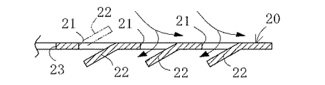
上記下ケース3内には、金属製で円盤状のバッフルプレート20が下ケース3の底部に溜まるオイル液面の上方を覆うように設けられている。このバッフルプレート20には、図2及び3に示すように、オイル通過用の複数の通過孔21及び各通過孔21の下方を覆う覆い部22が設けられている。これら通過孔21及び覆い部22は、バッフルプレート20に形成された略コ字状の切込み27の内側部位を下方に折り曲げて同時に形成されている。また、上記通過孔21は、バッフルプレート20の半径方向及び円周方向に沿って複数形成されている。これらバッフルプレート20の半径方向に沿って形成される複数の通過孔21は、その孔面積がバッフルプレート20の遠心方向に向かって大きくなっている。さらに、このバッフルプレート20の中心部には、オイル通過用の中心孔23が形成されている。
In the
(2)遠心分離式オイルフィルタの作用
次に、上記構成のフィルタ1Aの作用について説明する。
図1中に実線矢印で示すように、オイル流入口6からハウジング4内に流入されるオイルは、オイル導入部10内を通って連通口13及び導入口12を介して遠心ロータ11内に導入される。そのオイルの導入により遠心ロータ11内のオイル圧力が高まり、噴射ノズル19から遠心ロータ11の接線方向に向かってオイルが噴射される。すると、その噴射オイルの噴射力により遠心ロータ11が所定方向(図1中に破線矢印で示す。)に回転され、その回転により遠心ロータ11内のオイル中に含まれるスラッジ等の異物Sが遠心分離され遠心ロータ11の内面で捕捉される。
なお、遠心ロータ11の内面で捕捉された異物Sは、ハウジング4及び遠心ロータ11を分解してロータ本体17及び蓋体18の内面を清掃することにより除去される。
(2) Action of Centrifugal Oil Filter Next, the action of the filter 1A having the above configuration will be described.
As shown by solid line arrows in FIG. 1, the oil flowing into the
The foreign matter S captured on the inner surface of the
上記噴射ノズル19からの噴射オイルの一部は、バッフルプレート20に衝突してから通過孔21及び中心孔23を介して下ケース3の底部に落下されオイル流出口7からハウジング4の外部に排出される。また、図3中に実線矢印で示すように、噴射ノズル19からの噴射オイルの一部は、通過孔を通過して覆い部22に衝突してその勢いが弱められてから下ケース3の底部に落下されオイル流出口7からハウジング4の外部に排出される。
なお、オイル流出口7からハウジング4の外部に排出されたオイルは、オイル管25(図1参照)を介して図示しないエンジンのオイルパンに回収される。
Part of the injection oil from the
The oil discharged from the
(3)実施例1の効果
以上より、本実施例1のフィルタ1Aでは、下ケース3の底部内にバッフルプレート20を設けたので、このバッフルプレート20により噴射ノズル19からの噴射オイルがハウジング4の底部に溜まるオイル液面に直接衝突することを抑制でき、オイル中の気泡の発生を抑制することができる。その結果、気泡によるオイルの寿命低下、エンジン潤滑不良及び作動油圧の低下といった不具合を防ぐことができる。
(3) Effect of Embodiment 1 As described above, in the filter 1A of Embodiment 1, the
また、本実施例1では、バッフルプレート20に、オイル通過用の通過孔21及び通過孔21の下方を覆う覆い部22を設けたので、噴射ノズル19からの噴射オイルの一部を通過孔21を通過させ覆い部22に衝突させてその勢いを弱めてから下ケース3の底部に迅速に落下させることができ、バッフルプレート20上でのオイルの溜まりを抑制することができる。
Further, in the first embodiment, the
また、本実施例1では、バッフルプレート20に、その半径方向に沿って複数の通過孔21を形成し、これら複数の通過孔21の孔面積をバッフルプレート20の遠心方向に向かって大きくなるようにしたので、エンジン高回転時等に噴射ノズル19から勢いよくバッフルプレート20の外周側まで拡散して噴射されるオイルが、比較的孔面積の大きな通過孔21を介して下ケース3の底部に迅速に落下される。これにより、エンジン高回転時等に潤滑経路で大量のオイルを循環させたい場合に好適に対応することができる。
In the first embodiment, a plurality of passage holes 21 are formed in the
さらに、本実施例1では、バッフルプレート20に形成された略コ字状の切込み27の内側部位を下方に折り曲げて通過孔21及び覆い部22を同時に形成するようにしたので、通過孔21及び覆い部22をより容易に作成することができる。
Furthermore, in the first embodiment, the inner portion of the substantially
(参考例)
次に、参考例に係る遠心分離式オイルフィルタ(以下、単に「フィルタ」とも略記する。)について説明する。なお、本参考例に係るフィルタにおいて、上記実施例1のフィルタ1Aと略同じ構成部位には同符合を付けて詳説を省略し、両者の相違点であるバッフルプレートについて主に説明する。
( Reference example )
Next, a centrifugal oil filter (hereinafter simply abbreviated as “filter”) according to a reference example will be described. In the filter according to this reference example , the same components as those of the filter 1A of the first embodiment are denoted by the same reference numerals, and detailed description thereof is omitted. The baffle plate which is the difference between the two is mainly described.
本参考例に係るフィルタ1Bでは、図4に示すように、下方に向かって縮径する円錐状のバッフルプレート30が下ケース3の底部に溜まるオイル液面の上方を覆うように下ケース3内に設けられている。このバッフルプレート30には、図5及び6に示すように、その中心部にオイル通過用の中心孔31が形成されている。また、このバッフルプレート30の上面には、バッフルプレート30上のオイルを案内する螺旋状の案内壁32が設けられている。さらに、このバッフルプレート30には、隣接する案内壁32のうちの外周側の案内壁32の近傍にオイル通過用の通過孔33が形成されている。
In the filter 1B according to this reference example , as shown in FIG. 4, a
(2)遠心分離式オイルフィルタの作用
次に、上記構成のフィルタ1Bの作用について説明する。
図4に示すように、噴射ノズル19からの噴射オイルの一部は、バッフルプレート30に衝突してからバッフルプレート30上を案内壁32により案内され螺旋状に流れてから中心孔31を介して下ケース3の底部に落下されオイル流出口7からハウジング4の外部に排出される。また、エンジン高回転時等に噴射ノズル19からの噴射オイル量が比較的多いときには、図6中に実線矢印で示すように、バッフルプレート30上を螺旋状に流れるオイルが通過孔33を介して下ケース3の底部に迅速に落下されオイル流出口7からハウジング4の外部に排出される。
(2) Operation of Centrifugal Oil Filter Next, the operation of the filter 1B having the above configuration will be described.
As shown in FIG. 4, a part of the injection oil from the
(3)参考例の効果
以上より、本参考例のフィルタ1Bでは、上記実施例1のフィルタ1Aと略同様の作用・効果を発揮できることに加えて、円錐状のバッフルプレート30の上面に、オイルを案内する螺旋状の案内壁32を設けたので、バッフルプレート30に衝突したオイルがバッフルプレート30上を案内壁32により案内され螺旋状に時間をかけて流れるので、バッフルプレート30上を流れるオイル中に含まれる気泡が自然脱泡され、オイル中の気泡の発生をより確実に抑制できる。
(3) From the above effect of the reference example, the filter 1B of the present embodiment, in addition to exhibiting the filter 1A substantially the same operation and effects of the first embodiment, the upper surface of the
さらに、上記参考例では、バッフルプレート30に、隣接する案内壁32のうちの外周側の案内壁32の近傍にオイル通過用の通過孔33を形成したので、エンジン高回転時等に噴射ノズル19からの噴射オイル量が比較的多いときに、バッフルプレート30上を螺旋状に流れるオイルが通過孔33を介してハウジング4の底部に迅速に落下されるので、エンジン高回転時等に潤滑経路で大量のオイルを循環させたい場合に好適に対応することができる。
Further, in the above reference example , since the
尚、本発明においては、上記実施例に限られず、目的、用途に応じて本発明の範囲内で種々変更した実施例とすることができる。即ち、上記実施例1及び参考例では、下ケース3の底部内に1枚のバッフルプレート20,30を設けるようにしたが、これに限定されず、例えば、噴射オイルの噴射軌跡に沿って複数枚の分割バッフルプレートを設けるようにしてもよい。
In the present invention, the present invention is not limited to the above embodiment, and various modifications can be made within the scope of the present invention depending on the purpose and application. That is, in the first embodiment and the reference example , the
また、上記実施例1及び参考例では、遠心分離される異物Sを遠心ロータ11の内面で捕捉するようにしたが、これに限定されず、例えば、遠心ロータ11内に異物捕捉用の内筒や濾材等を設けるようにしてもよい。
In the first embodiment and the reference example , the foreign substance S to be centrifuged is captured by the inner surface of the
また、上記実施例1では、通過孔21の下方を覆う覆い部22を例示したが、これに限定されず、例えば、図3中に仮想線で示すように、通過孔21の上方を覆う覆い部22としてもよい。
Moreover, in the said Example 1, although the
また、上記実施例1では、バッフルプレート20に形成された略コ字状の切込み27の内側部位を折り曲げて覆い部22を形成するようにしたが、これに限定されず、例えば、バッフルプレート20とは別体の覆い部材をバッフルプレート20に後付けするようにしてもよい。
Moreover, in the said Example 1, although the inside part of the substantially
また、上記実施例1では、円盤状のバッフルプレート20を例示したが、これに限定されず、例えば、下方に向かって縮径する円錐状のバッフルプレート20としてもよい。
Moreover, in the said Example 1, although the disk-shaped
また、上記参考例では、案内壁32を設けてなる円錐状のバッフルプレート30を備えるフィルタ1Bを例示したが、これに限定されず、例えば、図7に示すように、案内壁を設けていない円錐状のバッフルプレート40を備えるフィルタ1Cとしてもよい。この場合でも、バッフルプレート40に衝突したオイルがバッフルプレート40上を外周側から中心側に向かって時間をかけて流れてから中心孔41を介してハウジング4の底部に落下されるので、バッフルプレート40上を流れるオイル中に含まれる気泡が自然脱泡され、オイル中の気泡の発生をより確実に抑制できる。
In the above reference example , the filter 1B including the
さらに、上記参考例において、例えば、図6中に仮想線で示すように、バッフルプレート30の下側に、このバッフルプレート30と略同じ構成の他のバッフルプレート35を設けてなる2段構造としたり、バッフルプレート30の下側に上記バッフルプレート40(図7参照)を設けてなる2段構造としたりしてもよい。また、上記実施例1において、例えば、バッフルプレート20の下側に、上記バッフルプレート30又は上記バッフルプレート40を設けてなる2段構造としてもよい。
Furthermore, in the above reference example , for example, as shown by the phantom line in FIG. 6, a two-stage structure in which another
オイル中に含まれる異物を除去するフィルタとして広く利用される。特に、エンジンオイル中に含まれるスラッジ等の異物を除去するフィルタとして好適に利用される。 It is widely used as a filter for removing foreign substances contained in oil. In particular, it is suitably used as a filter for removing foreign matters such as sludge contained in engine oil.
1A〜1C;遠心分離式オイルフィルタ、4;ハウジング、6;オイル流入口、7;オイル流出口、10;オイル導入部、11;遠心ロータ、19;噴射ノズル、20,30,40;バッフルプレート、21,33;通過孔、22;覆い部、23,31;中心孔、32;案内壁。 1A to 1C; centrifugal oil filter, 4; housing, 6; oil inlet, 7; oil outlet, 10; oil inlet, 11; centrifugal rotor, 19; injection nozzle, 20, 30, 40; 2, 33; Passing hole, 22; Cover, 23, 31; Center hole, 32; Guide wall.
Claims (3)
前記ハウジング内で回転自在に支持される容器状の遠心ロータと、
前記下ケースの底部中央側から上方に延びて前記遠心ロータを回転自在に支持する中空軸状に形成され、その下端側が前記オイル流入口に連なり該オイル流入口から前記ハウジング内に流入されるオイルを前記遠心ロータ内に導入するオイル導入部と、
前記遠心ロータに設けられ、該遠心ロータの接線方向で且つ水平に対して下方に傾斜する方向に指向して該遠心ロータ内に導入されたオイルを外部に噴射する噴射ノズルと、
前記下ケースの底部に溜まるオイル液面の上方を覆うように該下ケース内に設けられ、前記噴射ノズルからの噴射オイルが該下ケースの底部に溜まるオイル液面に直接衝突することを抑制するバッフルプレートと、を備え、
前記バッフルプレートには、前記遠心ロータの回転軸を中心とする円弧状に形成されたオイル通過用の通過孔、及び該通過孔の下方を覆うように該通過孔の外周側から内周側に向かって下方に傾斜して延びる覆い部が設けられていることを特徴とする遠心分離式オイルフィルタ。 A housing having a bottomed cylindrical upper case having a lower opening, and a lower case removably attached to the upper case and having an oil inlet and an oil outlet formed therein;
A container-like centrifugal rotor rotatably supported in the housing;
Oil that extends upward from the center of the bottom of the lower case and has a hollow shaft shape that rotatably supports the centrifugal rotor, and has a lower end connected to the oil inlet and flows into the housing from the oil inlet. An oil introduction part for introducing the oil into the centrifugal rotor;
An injection nozzle that is provided in the centrifugal rotor and injects oil introduced into the centrifugal rotor in a direction tangential to the centrifugal rotor and inclined downward with respect to the horizontal ;
It is provided in the lower case so as to cover the upper part of the oil level accumulated at the bottom of the lower case, and the injection oil from the injection nozzle is prevented from directly colliding with the oil level accumulated at the bottom of the lower case. includes a baffle plate, the,
The baffle plate has an oil passage passage hole formed in an arc shape centered on the rotation axis of the centrifugal rotor, and an outer periphery side of the passage hole so as to cover a lower portion of the passage hole. A centrifugal oil filter, characterized in that a cover portion that is inclined and extended downward is provided .
Priority Applications (1)
| Application Number | Priority Date | Filing Date | Title |
|---|---|---|---|
| JP2008003659A JP4983611B2 (en) | 2008-01-10 | 2008-01-10 | Centrifugal oil filter |
Applications Claiming Priority (1)
| Application Number | Priority Date | Filing Date | Title |
|---|---|---|---|
| JP2008003659A JP4983611B2 (en) | 2008-01-10 | 2008-01-10 | Centrifugal oil filter |
Publications (2)
| Publication Number | Publication Date |
|---|---|
| JP2009167812A JP2009167812A (en) | 2009-07-30 |
| JP4983611B2 true JP4983611B2 (en) | 2012-07-25 |
Family
ID=40969285
Family Applications (1)
| Application Number | Title | Priority Date | Filing Date |
|---|---|---|---|
| JP2008003659A Expired - Fee Related JP4983611B2 (en) | 2008-01-10 | 2008-01-10 | Centrifugal oil filter |
Country Status (1)
| Country | Link |
|---|---|
| JP (1) | JP4983611B2 (en) |
Families Citing this family (7)
| Publication number | Priority date | Publication date | Assignee | Title |
|---|---|---|---|---|
| DE202005020012U1 (en) * | 2005-12-22 | 2007-05-10 | Hengst Gmbh & Co.Kg | Centrifuge for cleaning a liquid |
| RU2470715C1 (en) * | 2011-07-21 | 2012-12-27 | Открытое акционерное общество "Алтай-кокс" | Centrifuge |
| US20150241371A1 (en) | 2012-11-28 | 2015-08-27 | Panasonic Healthcare Holdings Co., Ltd. | Biological information measuring device, bio sensor system, and error detection method for biological information measuring device |
| JP6336037B2 (en) * | 2014-02-25 | 2018-06-06 | 東京濾器株式会社 | Oil separator |
| JP6255476B2 (en) * | 2014-02-25 | 2017-12-27 | 東京濾器株式会社 | Oil separator |
| US10569206B2 (en) * | 2014-02-26 | 2020-02-25 | Tokyo Roki Co., Ltd. | Oil separator |
| CN113405286A (en) * | 2021-07-19 | 2021-09-17 | 珠海格力电器股份有限公司 | Oil separator, condenser and refrigeration plant |
Family Cites Families (3)
| Publication number | Priority date | Publication date | Assignee | Title |
|---|---|---|---|---|
| JPS4713667Y1 (en) * | 1970-02-20 | 1972-05-18 | ||
| JPH05187215A (en) * | 1992-01-13 | 1993-07-27 | Mazda Motor Corp | Crank chamber structure of engine |
| GB2314036B (en) * | 1996-06-10 | 2000-02-02 | Fram Europ | Centrifugal filter |
-
2008
- 2008-01-10 JP JP2008003659A patent/JP4983611B2/en not_active Expired - Fee Related
Also Published As
| Publication number | Publication date |
|---|---|
| JP2009167812A (en) | 2009-07-30 |
Similar Documents
| Publication | Publication Date | Title |
|---|---|---|
| JP4983611B2 (en) | Centrifugal oil filter | |
| JP6114384B2 (en) | Centrifuge | |
| JP5425104B2 (en) | Separator for separating gas-liquid mixture and method for separating liquid from gas-liquid mixture | |
| JP6480594B2 (en) | Centrifuge for purifying gas | |
| JP4678617B2 (en) | Additional device for swirling microbubble generator | |
| JP2007263066A (en) | Gas-liquid separator | |
| JP2008540908A (en) | Device for purifying gas when exhausting crank housing | |
| JP5439026B2 (en) | Gas-liquid separator | |
| JP4480615B2 (en) | Oil tank | |
| CN108361231B (en) | Lubricant reservoir for a hydraulic system | |
| WO2014014002A1 (en) | Gas absorption tower | |
| JP5510788B2 (en) | Steam separator | |
| CN209383532U (en) | A kind of chemical waste liquid deodorization filter centrifugation machine equipment | |
| KR100978345B1 (en) | Centrifugal filter with beveled nozzle | |
| JP5543187B2 (en) | Reservoir tank | |
| JP4450227B2 (en) | Gas-liquid separator and oil tank structure | |
| JP5651701B2 (en) | Oil-cooled compressor receiver tank | |
| JP7013408B2 (en) | Gas-liquid separator | |
| KR20230097193A (en) | Centrifuge with a stack of disks | |
| EP1691932B1 (en) | A centrifugal separator | |
| JP5490589B2 (en) | Suction collection device | |
| CN106745503B (en) | Drainage device suitable for dirty oil water separator | |
| KR102562109B1 (en) | Rotor assembly of centrifugal oil cleaner | |
| KR102551108B1 (en) | Centrifuge for Abrasive Sludge | |
| JPS59150519A (en) | Oil mist or dust removing apparatus |
Legal Events
| Date | Code | Title | Description |
|---|---|---|---|
| A621 | Written request for application examination |
Free format text: JAPANESE INTERMEDIATE CODE: A621 Effective date: 20100713 |
|
| A977 | Report on retrieval |
Free format text: JAPANESE INTERMEDIATE CODE: A971007 Effective date: 20110628 |
|
| A131 | Notification of reasons for refusal |
Free format text: JAPANESE INTERMEDIATE CODE: A131 Effective date: 20110705 |
|
| A521 | Written amendment |
Free format text: JAPANESE INTERMEDIATE CODE: A523 Effective date: 20110830 |
|
| TRDD | Decision of grant or rejection written | ||
| A01 | Written decision to grant a patent or to grant a registration (utility model) |
Free format text: JAPANESE INTERMEDIATE CODE: A01 Effective date: 20120327 |
|
| A01 | Written decision to grant a patent or to grant a registration (utility model) |
Free format text: JAPANESE INTERMEDIATE CODE: A01 |
|
| A61 | First payment of annual fees (during grant procedure) |
Free format text: JAPANESE INTERMEDIATE CODE: A61 Effective date: 20120409 |
|
| R150 | Certificate of patent or registration of utility model |
Free format text: JAPANESE INTERMEDIATE CODE: R150 Ref document number: 4983611 Country of ref document: JP Free format text: JAPANESE INTERMEDIATE CODE: R150 |
|
| FPAY | Renewal fee payment (event date is renewal date of database) |
Free format text: PAYMENT UNTIL: 20150511 Year of fee payment: 3 |
|
| FPAY | Renewal fee payment (event date is renewal date of database) |
Free format text: PAYMENT UNTIL: 20150511 Year of fee payment: 3 |
|
| R250 | Receipt of annual fees |
Free format text: JAPANESE INTERMEDIATE CODE: R250 |
|
| R250 | Receipt of annual fees |
Free format text: JAPANESE INTERMEDIATE CODE: R250 |
|
| R250 | Receipt of annual fees |
Free format text: JAPANESE INTERMEDIATE CODE: R250 |
|
| R250 | Receipt of annual fees |
Free format text: JAPANESE INTERMEDIATE CODE: R250 |
|
| R250 | Receipt of annual fees |
Free format text: JAPANESE INTERMEDIATE CODE: R250 |
|
| R250 | Receipt of annual fees |
Free format text: JAPANESE INTERMEDIATE CODE: R250 |
|
| LAPS | Cancellation because of no payment of annual fees |