JP4982181B2 - Power tool with angle drive and pinion adjustment - Google Patents
Power tool with angle drive and pinion adjustment Download PDFInfo
- Publication number
- JP4982181B2 JP4982181B2 JP2006532229A JP2006532229A JP4982181B2 JP 4982181 B2 JP4982181 B2 JP 4982181B2 JP 2006532229 A JP2006532229 A JP 2006532229A JP 2006532229 A JP2006532229 A JP 2006532229A JP 4982181 B2 JP4982181 B2 JP 4982181B2
- Authority
- JP
- Japan
- Prior art keywords
- drive spindle
- power tool
- pinion
- inner ring
- housing
- Prior art date
- Legal status (The legal status is an assumption and is not a legal conclusion. Google has not performed a legal analysis and makes no representation as to the accuracy of the status listed.)
- Active
Links
- 230000002093 peripheral effect Effects 0.000 claims description 3
- 230000008878 coupling Effects 0.000 claims 6
- 238000010168 coupling process Methods 0.000 claims 6
- 238000005859 coupling reaction Methods 0.000 claims 6
- 229910000831 Steel Inorganic materials 0.000 description 1
- 230000005540 biological transmission Effects 0.000 description 1
- 239000000463 material Substances 0.000 description 1
- 239000010959 steel Substances 0.000 description 1
Images


Classifications
-
- B—PERFORMING OPERATIONS; TRANSPORTING
- B25—HAND TOOLS; PORTABLE POWER-DRIVEN TOOLS; MANIPULATORS
- B25F—COMBINATION OR MULTI-PURPOSE TOOLS NOT OTHERWISE PROVIDED FOR; DETAILS OR COMPONENTS OF PORTABLE POWER-DRIVEN TOOLS NOT PARTICULARLY RELATED TO THE OPERATIONS PERFORMED AND NOT OTHERWISE PROVIDED FOR
- B25F5/00—Details or components of portable power-driven tools not particularly related to the operations performed and not otherwise provided for
- B25F5/001—Gearings, speed selectors, clutches or the like specially adapted for rotary tools
-
- F—MECHANICAL ENGINEERING; LIGHTING; HEATING; WEAPONS; BLASTING
- F16—ENGINEERING ELEMENTS AND UNITS; GENERAL MEASURES FOR PRODUCING AND MAINTAINING EFFECTIVE FUNCTIONING OF MACHINES OR INSTALLATIONS; THERMAL INSULATION IN GENERAL
- F16C—SHAFTS; FLEXIBLE SHAFTS; ELEMENTS OR CRANKSHAFT MECHANISMS; ROTARY BODIES OTHER THAN GEARING ELEMENTS; BEARINGS
- F16C35/00—Rigid support of bearing units; Housings, e.g. caps, covers
- F16C35/04—Rigid support of bearing units; Housings, e.g. caps, covers in the case of ball or roller bearings
- F16C35/06—Mounting or dismounting of ball or roller bearings; Fixing them onto shaft or in housing
- F16C35/063—Fixing them on the shaft
-
- F—MECHANICAL ENGINEERING; LIGHTING; HEATING; WEAPONS; BLASTING
- F16—ENGINEERING ELEMENTS AND UNITS; GENERAL MEASURES FOR PRODUCING AND MAINTAINING EFFECTIVE FUNCTIONING OF MACHINES OR INSTALLATIONS; THERMAL INSULATION IN GENERAL
- F16C—SHAFTS; FLEXIBLE SHAFTS; ELEMENTS OR CRANKSHAFT MECHANISMS; ROTARY BODIES OTHER THAN GEARING ELEMENTS; BEARINGS
- F16C35/00—Rigid support of bearing units; Housings, e.g. caps, covers
- F16C35/04—Rigid support of bearing units; Housings, e.g. caps, covers in the case of ball or roller bearings
- F16C35/06—Mounting or dismounting of ball or roller bearings; Fixing them onto shaft or in housing
- F16C35/067—Fixing them in a housing
-
- F—MECHANICAL ENGINEERING; LIGHTING; HEATING; WEAPONS; BLASTING
- F16—ENGINEERING ELEMENTS AND UNITS; GENERAL MEASURES FOR PRODUCING AND MAINTAINING EFFECTIVE FUNCTIONING OF MACHINES OR INSTALLATIONS; THERMAL INSULATION IN GENERAL
- F16H—GEARING
- F16H57/00—General details of gearing
- F16H57/02—Gearboxes; Mounting gearing therein
- F16H57/021—Shaft support structures, e.g. partition walls, bearing eyes, casing walls or covers with bearings
- F16H57/022—Adjustment of gear shafts or bearings
- F16H2057/0221—Axial adjustment
-
- F—MECHANICAL ENGINEERING; LIGHTING; HEATING; WEAPONS; BLASTING
- F16—ENGINEERING ELEMENTS AND UNITS; GENERAL MEASURES FOR PRODUCING AND MAINTAINING EFFECTIVE FUNCTIONING OF MACHINES OR INSTALLATIONS; THERMAL INSULATION IN GENERAL
- F16H—GEARING
- F16H55/00—Elements with teeth or friction surfaces for conveying motion; Worms, pulleys or sheaves for gearing mechanisms
- F16H55/02—Toothed members; Worms
- F16H55/17—Toothed wheels
- F16H55/18—Special devices for taking up backlash
- F16H55/20—Special devices for taking up backlash for bevel gears
-
- Y—GENERAL TAGGING OF NEW TECHNOLOGICAL DEVELOPMENTS; GENERAL TAGGING OF CROSS-SECTIONAL TECHNOLOGIES SPANNING OVER SEVERAL SECTIONS OF THE IPC; TECHNICAL SUBJECTS COVERED BY FORMER USPC CROSS-REFERENCE ART COLLECTIONS [XRACs] AND DIGESTS
- Y10—TECHNICAL SUBJECTS COVERED BY FORMER USPC
- Y10T—TECHNICAL SUBJECTS COVERED BY FORMER US CLASSIFICATION
- Y10T74/00—Machine element or mechanism
- Y10T74/19—Gearing
- Y10T74/19642—Directly cooperating gears
- Y10T74/1966—Intersecting axes
- Y10T74/19665—Bevel gear type
-
- Y—GENERAL TAGGING OF NEW TECHNOLOGICAL DEVELOPMENTS; GENERAL TAGGING OF CROSS-SECTIONAL TECHNOLOGIES SPANNING OVER SEVERAL SECTIONS OF THE IPC; TECHNICAL SUBJECTS COVERED BY FORMER USPC CROSS-REFERENCE ART COLLECTIONS [XRACs] AND DIGESTS
- Y10—TECHNICAL SUBJECTS COVERED BY FORMER USPC
- Y10T—TECHNICAL SUBJECTS COVERED BY FORMER US CLASSIFICATION
- Y10T74/00—Machine element or mechanism
- Y10T74/19—Gearing
- Y10T74/19642—Directly cooperating gears
- Y10T74/19688—Bevel
Description
本発明は、ハウジングと、アングルドライブ装置(angle drive)を介して回転モータを接続した出力軸とを有し、アングルドライブ装置が、ピニオンをもつ駆動スピンドル及び出力軸に接続されたかさ歯車と、ハウジングに対して駆動スピンドル軸方向に支持するスラスト軸受とを有している動力工具に関する。 The present invention includes a housing and an output shaft connected to a rotary motor via an angle drive, and the angle drive includes a drive spindle having a pinion and a bevel gear connected to the output shaft. The present invention relates to a power tool having a thrust bearing that supports a housing in a driving spindle axial direction.
この形式の動力工具では、アングルドライブ装置の有効寿命が制限されるという問題がある。特に、この問題は、比較的大きなトルク負荷を伝達することになる動力レンチにおいて生じる。これは、主として、アングルドライブ装置、歯車及び軸受が共に大きな伝達トルク負荷に対して寸法が小さいためであり、このことは歯車の歯フランクにおける接触圧が非常に高いことを意味している。この高い接触圧に対処するために、駆動ピニオンとかさ歯車との歯車の歯の係合が全ての負荷状態において絶対的に正しいこと、また当然歯車が適切に熱処理し機械加工した適当な材料から成ることは極めて重要である。 This type of power tool has a problem that the useful life of the angle drive device is limited. In particular, this problem occurs in a power wrench that will transmit a relatively large torque load. This is mainly due to the fact that the angle drive device, the gear and the bearing are all small in size for a large transmission torque load, which means that the contact pressure at the tooth flank of the gear is very high. To cope with this high contact pressure, the gear tooth engagement between the drive pinion and the bevel gear is absolutely correct under all load conditions, and of course from a suitable material that the gear has been properly heat treated and machined. It is extremely important to make it.
上記の問題を解決しようとする対処の規模を例示するため、自動車の歯車ボックスと比較すると、自動車の歯車ボックス内の歯車が動力レンチの場合と同じレベルに応力を受けた場合に、自動車の歯車ボックス内の歯車の有効寿命は通常の有効寿命の1%未満に低減される。 To illustrate the scale of the action to be taken to solve the above problem, when compared to a car gear box, the car gears when the gears in the car gear box are stressed to the same level as the power wrench. The useful life of the gear in the box is reduced to less than 1% of the normal useful life.
ピニオンとかさ歯車の歯とを正確に係合させるためには、歯車間の遊びは極めて重要である。この遊びは主としてピニオン及び従って駆動スピンドルの軸方向位置に依存している。かさ歯車に対するピニオンの軸方向位置の許容誤差は±0.01mm程度である。ピニオンの位置を調整する通常の仕方はシームを用いることにあるが、技法が煩雑でありしかも精度が十分でない。シームと駆動スピンドルの軸受とハウジングとの間の多重接触表面が、軸受の僅かに弾性の支持体に加わり、駆動スピンドル及びピニオン位置の±0.01mmの精度は全く保証されない。さらに、シーム技法はどちらかと言えば時間の無駄であり、多量生産には適さない。 In order to accurately engage the pinion and the teeth of the bevel gear, the play between the gears is extremely important. This play depends mainly on the pinion and thus on the axial position of the drive spindle. The tolerance of the axial position of the pinion with respect to the bevel gear is about ± 0.01 mm. The usual way to adjust the pinion position is to use seams, but the technique is cumbersome and not accurate enough. Multiple contact surfaces between the bearing and housing of the seam and drive spindle add to the slightly elastic support of the bearing and no accuracy of ± 0.01 mm at the drive spindle and pinion positions is guaranteed. Furthermore, the seam technique is rather time consuming and not suitable for mass production.
軸受の遊びを調整する別の方法は、玉レースの一つを軸方向に固定するためにねじ込む支持型要素を用いることにある。しかし、この解決法には別の困難性が伴い、すなわち玉レースが動作中にレースの支持体に対して回転してはならないが、調整中には容易に動くことができる必要がある。これらの二つの相反する特徴を得ることは極めて難しい。 Another way of adjusting the play of the bearings is to use a supporting element that is screwed on to fix one of the ball races in the axial direction. However, this solution comes with another difficulty: the ball race must not rotate with respect to the support of the race during operation, but it must be able to move easily during adjustment. Obtaining these two conflicting features is extremely difficult.
本発明の主目的は、ピニオンとかさ歯車の遊びを十分に正確に設定するのを容易にしかも安全に行うことのできるアングルドライブ装置を備えた動力工具を提供することにある。 A main object of the present invention is to provide a power tool including an angle drive device that can easily and safely set play of a pinion and a bevel gear sufficiently accurately.
この目的は、明細書の以下の説明及び特許請求の範囲において二つの選択的な実施形態として記載する改良型のピニオン軸受装置によって達成される。 This object is achieved by an improved pinion bearing device which is described as two alternative embodiments in the following description of the specification and in the claims.
以下、添付図面を参照して本発明の二つの好ましい実施形態について詳細に説明する。 Hereinafter, two preferred embodiments of the present invention will be described in detail with reference to the accompanying drawings.
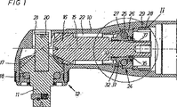
図1及び図2には動力工具を断面図で示し、該動力工具は、回転モータ(図示していない)によって駆動される出力軸11を支持するハウジング10、及びモータを出力軸11に接続するアングルドライブ装置12を有している。アングルドライブ装置12は、モータに結合されかつピニオン16と一部片部材として一体に形成された駆動スピンドル15と、出力軸11と一体に形成したかさ歯車17とを有している。前方端部において、出力軸11は玉軸受18にジャーナル軸受され、一方、出力軸11の後方端部は伸張部20を有し、この伸張部20は針状ころ軸受21によってハウジング10に支持されている。
1 and 2 show a power tool in cross-sectional view, which power tool connects a
駆動スピンドル15は、半径方向力をハウジング10に伝達する針状ころ軸受22及び軸方向力をハウジング10に伝達する玉軸受24によってハウジング10に回転的にジャーナル軸受されている。アングルドライブ装置12を介してのトルク負荷の伝達時に、駆動スピンドル15及び出力軸11は、軸受18、24を介してハウジング10に伝達される軸方向力を受ける。
The
軸受24は、いかなる分離玉ケージなしに、十分な数の玉25を備えた形式のアンギュラーコンタクト軸受を備えている。軸受24は、ハウジング10における肩部27とハウジング10におけるねじ部分29と共動するリングねじ28との間に固定された外側リング26を備えている。軸受24はまた、内側リング31を備え、この内側リング31の前方端部には、駆動スピンドル15におけるねじ部分33と共動する内側ねじ32が形成されている。内側リング31の後方端部には、環状ロック要素35と共動する多数の軸方向に向いた歯34が形成されている。
The
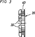
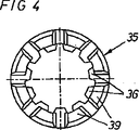
ロック要素35は、駆動スピンドル15における軸方向に向いたスプライン37と共動する内方に向いた歯36を備え、また内側リング31における歯34と係合する軸方向に向いた歯39を備えている。ロック要素35はまた、Oリングシール41を支持する周囲溝40を備えている。ロック要素35をロック位置に止めるために、すなわち内側リング31における歯と駆動スピンドルスプライン37と両方との係合において、駆動スピンドル15における周囲溝43に支持されるロックリング42が設けられている。
The
アングルドライブ装置12を組立てる際に、出力軸11及び軸受18がまず配置される。その後、スラスト軸受24は、内側リング31を駆動スピンドルの部分33を可能な限りねじ込んで、駆動スピンドル15に組立て装着される。その後、駆動スピンドル15は軸受24と共に、軸受24の外側リング26がハウジング10における肩部27に当接するまで、ハウジング10内に導入される。外側リング26は、リングねじ28を装着し締付けることによってハウジング10に固着される。この状態において、ピニオン16はかさ歯車17と係合するが、歯車の歯間には実質的な遊びが存在している。
When the angle drive device 12 is assembled, the output shaft 11 and the
次に、ピニオン16とかさ歯車17との間の軸方向遊びは、ピニオン16及びかさ歯車17の歯車の歯間が正しく係合するように設定されることになる。これは、内側リング31が後方へ動き外側リング26に対して玉25を押圧するように、スラスト軸受24の内側リング31を回転させることによって行われる。これにより、駆動スピンドル15が順方向へ動くことになり、そしてピニオン16とかさ歯車17との間の遊びがゼロである状態に駆動スピンドル15がなり、内側リング31の回転に対してある一定の抵抗を受ける。そして、内側リング31は、アングルドライブ装置における正しい所望の遊びを得るために、ある一定の予定の角度後方へ回転される。ピニオン16とかさ歯車17との正しい遊びが設定される際に、ロック要素35は、軸方向に向いた歯39が内側リング31の歯34と係合するまで、駆動スピンドルのスプライン37に沿って押し進められる。その後、ロックリング42は駆動スピンドル15における溝43に装着される。次に、内側リング31は回転的にロックされ、そしてピニオン16とかさ歯車17との間の設定遊びは安全に維持される。
Next, the axial play between the
図5に示す実施形態では、軸受124の内側リングは二つの半体131a、131bに分けられ、これら半体の一方131aは、駆動スピンドル115における肩部127に対して支持されている。内側リングの他方の半体131bは、ロックリング128によって軸方向にロックされている。軸受124の外側リング126は、ハウジング110のねじ部分133と共動するように構成された外部ねじ132を備えた後方伸張部を有している。さらに、外側リング126には二つの溝(図示されていない)が形成され、これらの溝に、外側リング126における図示していないこれらの溝と共動する二つの内方に向いた歯136を備えたシート鋼座金の形態のロック要素135が装着される。外側リング126は、ロック要素135における後方フランジ142が変形してハウジング110の前方部分の端部における軸方向に向いた歯134と係合する更なる回転に対して安全にロックされる。それにより、外側リング126は正しい位置に維持される。
In the embodiment shown in FIG. 5, the inner ring of the
本発明のこの実施形態によるスラスト軸受の組立ては上記の方法と同じであり、すなわち駆動スピンドル115と別個に軸受124を組立て、この組立体をハウジング110に挿入し、それにより、アングルドライブ装置を回転する際にトルク抵抗が得られるまで、ハウジング110のねじ部分133に外側リング126をねじ込む。そして、外側リング126は逆方向に予定の角度回転され、それにより、軸受124及び駆動スピンドル115を、ピニオン116とかさ歯車117との間の所望の歯車の歯の遊びに相当した距離引く。その後、ロック要素135はハウジング110における歯134と係合するように変形され、外側リング126の得られた角度位置を保証し、アングルドライブ装置の歯車の歯間の遊びを設定する。
The assembly of the thrust bearing according to this embodiment of the invention is the same as described above, i.e. assembling the
上記二つの軸受装置は、スラスト軸受の玉支持リングのいずれか一方が軸方向に調整でき、支持リングの他方がハウジング又は駆動スピンドルに択一的に堅固に固定されるという発明概念に基いている。このことは、アングルドライブ装置のかさ歯車とピニオンとの間の軸方向遊びの正確で単純な設定を意味している。 The above two bearing devices are based on the inventive concept that one of the ball support rings of the thrust bearing can be adjusted in the axial direction and the other of the support rings is alternatively firmly fixed to the housing or the drive spindle. . This means an accurate and simple setting of the axial play between the bevel gear and the pinion of the angle drive device.
Claims (5)
上記外側リング(26)がハウジング(10)に対して軸方向に固定され、
上記調整手段(32、33)が、
上記駆動スピンドル(15)におけるねじ部(33)と、
上記内側リング(31)と一体に形成され、前記内側リング(31)と駆動スピンドル(15)間の軸調整移動を達成するために、上記駆動スピンドル(15)における上記ねじ部(33)と共動するように構成された内部ねじ(32)と
を備え、また、
上記駆動スピンドル(15)の所望の軸方向位置が得られる際に、上記駆動スピンドル(15)に対して上記内側リング(31)を回転的にロックするカップリング手段(35)が設けられること
ことを特徴とする動力工具。A housing (10); an output shaft (11) driven by the rotary motor; and an angle drive device (12) connecting the rotary motor to the output shaft (11), the angle drive device (12) being A drive spindle (15) connected to the rotary motor and supporting the pinion (16) and a bevel gear (17) mounted on the output shaft (11), the drive spindle (15) is connected to the inner ring (31). ) And a ball bearing (24) having an outer ring (26), and adjusting means (32, 33) for setting the axial position of the drive spindle (15) and pinion (16) with respect to the bevel gear (17). ) In a power tool supported axially relative to the housing (10) by
The outer ring (26) is fixed axially relative to the housing (10);
The adjusting means (32, 33)
A threaded portion (33) in the drive spindle (15);
In order to achieve axial adjustment movement between the inner ring (31) and the drive spindle (15), it is formed integrally with the inner ring (31), and is coupled with the threaded portion (33) in the drive spindle (15). An internal screw (32) configured to move, and
Coupling means (35) for rotationally locking the inner ring (31) relative to the drive spindle (15) when a desired axial position of the drive spindle (15) is obtained is provided. Power tool characterized by
Applications Claiming Priority (3)
| Application Number | Priority Date | Filing Date | Title |
|---|---|---|---|
| SE0302623A SE526996C2 (en) | 2003-10-03 | 2003-10-03 | Power tool with angle gear and drive spindle adjustment |
| SE0302623-4 | 2003-10-03 | ||
| PCT/SE2004/001406 WO2005032769A1 (en) | 2003-10-03 | 2004-10-04 | Power tool with angle drive and pinion adjustment |
Publications (3)
| Publication Number | Publication Date |
|---|---|
| JP2007507360A JP2007507360A (en) | 2007-03-29 |
| JP2007507360A5 JP2007507360A5 (en) | 2012-04-19 |
| JP4982181B2 true JP4982181B2 (en) | 2012-07-25 |
Family
ID=29398648
Family Applications (1)
| Application Number | Title | Priority Date | Filing Date |
|---|---|---|---|
| JP2006532229A Active JP4982181B2 (en) | 2003-10-03 | 2004-10-04 | Power tool with angle drive and pinion adjustment |
Country Status (5)
| Country | Link |
|---|---|
| US (1) | US7963346B2 (en) |
| EP (1) | EP1667820B1 (en) |
| JP (1) | JP4982181B2 (en) |
| SE (1) | SE526996C2 (en) |
| WO (1) | WO2005032769A1 (en) |
Families Citing this family (27)
| Publication number | Priority date | Publication date | Assignee | Title |
|---|---|---|---|---|
| SE529928C2 (en) * | 2006-05-09 | 2008-01-08 | Atlas Copco Tools Ab | Portable tool locking device |
| SE529929C2 (en) * | 2006-05-09 | 2008-01-08 | Atlas Copco Tools Ab | Portable tool with a freewheel lock of the drive shaft |
| JP2009174663A (en) * | 2008-01-25 | 2009-08-06 | Sumitomo Heavy Ind Ltd | Power transmission device with bevel gear |
| US20110139474A1 (en) * | 2008-05-05 | 2011-06-16 | Warren Andrew Seith | Pneumatic impact tool |
| US7886840B2 (en) * | 2008-05-05 | 2011-02-15 | Ingersoll-Rand Company | Motor assembly for pneumatic tool |
| US20090272556A1 (en) * | 2008-05-05 | 2009-11-05 | Ingersoll-Rand Company | Angle head and bevel gear for tool |
| SE533830C2 (en) * | 2009-06-11 | 2011-02-01 | Atlas Copco Tools Ab | Nut wrench with gearbox and parameter transducer |
| DE102009054929B4 (en) * | 2009-12-18 | 2022-08-11 | Robert Bosch Gmbh | Hand tool device |
| US20120011954A1 (en) * | 2010-07-13 | 2012-01-19 | Nomis Llc | Right Angle Drive Having Dual Shaft Bearings |
| US8925646B2 (en) | 2011-02-23 | 2015-01-06 | Ingersoll-Rand Company | Right angle impact tool |
| US9592600B2 (en) | 2011-02-23 | 2017-03-14 | Ingersoll-Rand Company | Angle impact tools |
| EP2505307B1 (en) * | 2011-03-31 | 2014-01-08 | Makita Corporation | Power tool |
| TW201347928A (en) * | 2012-05-30 | 2013-12-01 | Basso Ind Corp | Pneumatic tool with safety device |
| US20150314427A1 (en) * | 2012-12-21 | 2015-11-05 | Atlas Copco Industrial Technique Ab | Power tool attachment part |
| US9550283B2 (en) * | 2013-01-24 | 2017-01-24 | Ingersoll-Rand Company | Power tool with spindle lock |
| US9022888B2 (en) | 2013-03-12 | 2015-05-05 | Ingersoll-Rand Company | Angle impact tool |
| DE102013212193A1 (en) * | 2013-06-26 | 2014-12-31 | Robert Bosch Gmbh | Hand tool with a spindle locking device |
| DE102013212196A1 (en) * | 2013-06-26 | 2014-12-31 | Robert Bosch Gmbh | Hand tool with a spindle locking device |
| CN103836160A (en) * | 2014-02-19 | 2014-06-04 | 泰星减速机股份有限公司 | Cylindrical bevel gear speed reducer |
| US9812923B2 (en) | 2014-05-23 | 2017-11-07 | Aero Industries, Inc. | Gear motor |
| USD764248S1 (en) | 2015-04-22 | 2016-08-23 | Nomis Llc | Right angle drive |
| US11338426B2 (en) | 2015-11-02 | 2022-05-24 | Black & Decker, Inc. | Cordless power cutter |
| JP7080814B2 (en) * | 2015-12-11 | 2022-06-06 | アトラス・コプコ・インダストリアル・テクニーク・アクチボラグ | Power wrench with angle drive |
| USD789171S1 (en) | 2016-01-21 | 2017-06-13 | Nomis Llc | Right angle drive |
| WO2017204861A1 (en) * | 2016-05-26 | 2017-11-30 | Tate Elmer | Continuous-charging systems |
| USD907455S1 (en) * | 2019-05-21 | 2021-01-12 | Nomis Llc | Right angle drive attachment |
| USD907456S1 (en) | 2019-05-21 | 2021-01-12 | Nomis Llc | Right angle drill attachment |
Family Cites Families (21)
| Publication number | Priority date | Publication date | Assignee | Title |
|---|---|---|---|---|
| US2604795A (en) * | 1950-03-08 | 1952-07-29 | Milwaukee Electric Tool Corp | Angular drive |
| US2697362A (en) * | 1950-04-18 | 1954-12-21 | C H Keesling | Angle drive and bearing structure |
| US3838588A (en) * | 1971-05-14 | 1974-10-01 | A Johnson | Apparatus for setting unthreaded pull rivets |
| US3866692A (en) * | 1973-02-02 | 1975-02-18 | Rockwell International Corp | Power tools |
| US3901098A (en) * | 1973-12-17 | 1975-08-26 | Dotco Inc | Angle drive unit |
| US4215594A (en) * | 1978-07-14 | 1980-08-05 | Cooper Industries, Inc. | Torque responsive speed shift mechanism for power tool |
| US4403679A (en) * | 1981-04-01 | 1983-09-13 | Cooper Industries, Inc. | Angle drive lubricator |
| US4531847A (en) | 1983-11-28 | 1985-07-30 | The United States Of America As Represented By The Secretary Of The Army | Shaft-mounted equipments |
| EP0548717A1 (en) | 1991-12-21 | 1993-06-30 | Robert Bosch Gmbh | Hand tool machine with angle drive transmission |
| JPH06182674A (en) * | 1992-12-16 | 1994-07-05 | Makita Corp | Rotary impact tool |
| DE19704110B4 (en) | 1997-02-04 | 2008-08-14 | Robert Bosch Gmbh | Hand belt sander |
| US6766708B2 (en) * | 1997-08-18 | 2004-07-27 | Eddie L. Brooks | Gear ratio multiplier |
| US6142242A (en) * | 1999-02-15 | 2000-11-07 | Makita Corporation | Percussion driver drill, and a changeover mechanism for changing over a plurality of operating modes of an apparatus |
| DE10029277A1 (en) * | 2000-06-14 | 2001-12-20 | Bosch Gmbh Robert | Hand held machine tool comprises a support flange which is provided with a friction element on its side facing the disk shaped tool clamped onto the support flange |
| US6709161B2 (en) * | 2001-07-31 | 2004-03-23 | Nsk Ltd. | Angular contact ball bearing and spindle device |
| SE520640C2 (en) * | 2001-10-16 | 2003-08-05 | Atlas Copco Tools Ab | Handheld power tool with a rotating output shaft |
| SE523815C2 (en) * | 2002-05-22 | 2004-05-18 | Atlas Copco Tools Ab | Portable power tool with grease lubricated angular gear with separate grease distribution element |
| SE523780C2 (en) * | 2002-05-22 | 2004-05-18 | Atlas Copco Tools Ab | Portable power tool with grease lubricated angular gear whose grease-filled gearbox is divided by a disc-shaped element |
| GB2394517A (en) * | 2002-10-23 | 2004-04-28 | Black & Decker Inc | Powered hammer having a spindle lock with synchronising element |
| GB2394516A (en) * | 2002-10-23 | 2004-04-28 | Black & Decker Inc | Power tool |
| EP1468789A3 (en) * | 2003-04-17 | 2008-06-04 | BLACK & DECKER INC. | Clutch for rotary power tool and rotary power tool incorporating such clutch |
-
2003
- 2003-10-03 SE SE0302623A patent/SE526996C2/en not_active IP Right Cessation
-
2004
- 2004-10-04 US US10/574,534 patent/US7963346B2/en active Active
- 2004-10-04 EP EP04775500A patent/EP1667820B1/en active Active
- 2004-10-04 WO PCT/SE2004/001406 patent/WO2005032769A1/en active Application Filing
- 2004-10-04 JP JP2006532229A patent/JP4982181B2/en active Active
Also Published As
| Publication number | Publication date |
|---|---|
| EP1667820B1 (en) | 2011-06-15 |
| US7963346B2 (en) | 2011-06-21 |
| SE0302623D0 (en) | 2003-10-03 |
| SE526996C2 (en) | 2005-12-06 |
| SE0302623L (en) | 2005-04-04 |
| US20070181322A1 (en) | 2007-08-09 |
| WO2005032769A1 (en) | 2005-04-14 |
| JP2007507360A (en) | 2007-03-29 |
| EP1667820A1 (en) | 2006-06-14 |
Similar Documents
| Publication | Publication Date | Title |
|---|---|---|
| JP4982181B2 (en) | Power tool with angle drive and pinion adjustment | |
| JP2007507360A5 (en) | ||
| CN110886835B (en) | Anti-backlash mechanism based on low-speed worm gear and worm transmission pair | |
| JP2005255121A (en) | Electric power steering device | |
| US9096258B2 (en) | Gearbox assembly for electric power steering systems | |
| EP0752543B1 (en) | Eccentric orbiting type planetary gear device, and its manufacturing method | |
| US8297420B2 (en) | Method for manufacturing an overrunning clutch | |
| JP2003014056A (en) | Rotation transmission device, toothed rotor used for it, and manufacturing method for rotation transmission device | |
| WO2007144618A1 (en) | Adjuster for removing unwanted free play in a worm gear reduction unit in power assisted steering systems | |
| US7188557B2 (en) | Tightening tool | |
| US10919138B2 (en) | Power wrench with angle drive | |
| US20230024875A1 (en) | Gearbox assembly for an electric power steering apparatus | |
| JP2007107594A (en) | Rotary-linear motion converting mechanism | |
| JP5304305B2 (en) | Ball screw device | |
| JP3878047B2 (en) | Electric power steering device | |
| KR101696907B1 (en) | Wheel bearing and manufacturing method of the same | |
| CN218134989U (en) | Bearing pretightening force adjusting device and main shaft device | |
| JP2008309254A (en) | Assembling method of toroidal continuously variable transmission and toroidal continuously variable transmission | |
| JP2006046630A (en) | Joining method of helical gear to shaft member, and joining method of sun gear to rotating shaft in helical planetary gear reducer | |
| JP2006052801A (en) | Method of measuring clearance in bearing device for wheel | |
| JP2005153638A (en) | Electric power steering device | |
| JP4899900B2 (en) | Operating characteristic measuring device | |
| KR20110003080U (en) | Transmission for minimized division of universal milling upper head | |
| GB2466282A (en) | Method of machining a flange on a differential input pinion shaft | |
| JP2007085502A (en) | Ball screw mechanism |
Legal Events
| Date | Code | Title | Description |
|---|---|---|---|
| A621 | Written request for application examination |
Free format text: JAPANESE INTERMEDIATE CODE: A621 Effective date: 20071003 |
|
| A131 | Notification of reasons for refusal |
Free format text: JAPANESE INTERMEDIATE CODE: A131 Effective date: 20100929 |
|
| A601 | Written request for extension of time |
Free format text: JAPANESE INTERMEDIATE CODE: A601 Effective date: 20110104 |
|
| A602 | Written permission of extension of time |
Free format text: JAPANESE INTERMEDIATE CODE: A602 Effective date: 20110112 |
|
| A601 | Written request for extension of time |
Free format text: JAPANESE INTERMEDIATE CODE: A601 Effective date: 20110131 |
|
| A602 | Written permission of extension of time |
Free format text: JAPANESE INTERMEDIATE CODE: A602 Effective date: 20110207 |
|
| A601 | Written request for extension of time |
Free format text: JAPANESE INTERMEDIATE CODE: A601 Effective date: 20110228 |
|
| A602 | Written permission of extension of time |
Free format text: JAPANESE INTERMEDIATE CODE: A602 Effective date: 20110307 |
|
| A521 | Request for written amendment filed |
Free format text: JAPANESE INTERMEDIATE CODE: A523 Effective date: 20110323 |
|
| A131 | Notification of reasons for refusal |
Free format text: JAPANESE INTERMEDIATE CODE: A131 Effective date: 20110907 |
|
| A601 | Written request for extension of time |
Free format text: JAPANESE INTERMEDIATE CODE: A601 Effective date: 20111207 |
|
| A602 | Written permission of extension of time |
Free format text: JAPANESE INTERMEDIATE CODE: A602 Effective date: 20111214 |
|
| A601 | Written request for extension of time |
Free format text: JAPANESE INTERMEDIATE CODE: A601 Effective date: 20120110 |
|
| A602 | Written permission of extension of time |
Free format text: JAPANESE INTERMEDIATE CODE: A602 Effective date: 20120117 |
|
| A601 | Written request for extension of time |
Free format text: JAPANESE INTERMEDIATE CODE: A601 Effective date: 20120207 |
|
| A602 | Written permission of extension of time |
Free format text: JAPANESE INTERMEDIATE CODE: A602 Effective date: 20120214 |
|
| A524 | Written submission of copy of amendment under article 19 pct |
Free format text: JAPANESE INTERMEDIATE CODE: A524 Effective date: 20120305 |
|
| TRDD | Decision of grant or rejection written | ||
| A01 | Written decision to grant a patent or to grant a registration (utility model) |
Free format text: JAPANESE INTERMEDIATE CODE: A01 Effective date: 20120328 |
|
| A01 | Written decision to grant a patent or to grant a registration (utility model) |
Free format text: JAPANESE INTERMEDIATE CODE: A01 |
|
| A61 | First payment of annual fees (during grant procedure) |
Free format text: JAPANESE INTERMEDIATE CODE: A61 Effective date: 20120423 |
|
| FPAY | Renewal fee payment (event date is renewal date of database) |
Free format text: PAYMENT UNTIL: 20150427 Year of fee payment: 3 |
|
| R150 | Certificate of patent or registration of utility model |
Ref document number: 4982181 Country of ref document: JP Free format text: JAPANESE INTERMEDIATE CODE: R150 Free format text: JAPANESE INTERMEDIATE CODE: R150 |
|
| R250 | Receipt of annual fees |
Free format text: JAPANESE INTERMEDIATE CODE: R250 |
|
| R250 | Receipt of annual fees |
Free format text: JAPANESE INTERMEDIATE CODE: R250 |
|
| R250 | Receipt of annual fees |
Free format text: JAPANESE INTERMEDIATE CODE: R250 |
|
| R250 | Receipt of annual fees |
Free format text: JAPANESE INTERMEDIATE CODE: R250 |
|
| R250 | Receipt of annual fees |
Free format text: JAPANESE INTERMEDIATE CODE: R250 |
|
| R250 | Receipt of annual fees |
Free format text: JAPANESE INTERMEDIATE CODE: R250 |
|
| R250 | Receipt of annual fees |
Free format text: JAPANESE INTERMEDIATE CODE: R250 |
|
| R250 | Receipt of annual fees |
Free format text: JAPANESE INTERMEDIATE CODE: R250 |
|
| R250 | Receipt of annual fees |
Free format text: JAPANESE INTERMEDIATE CODE: R250 |
|
| R250 | Receipt of annual fees |
Free format text: JAPANESE INTERMEDIATE CODE: R250 |