JP4981775B2 - Agricultural machine - Google Patents
Agricultural machine Download PDFInfo
- Publication number
- JP4981775B2 JP4981775B2 JP2008236675A JP2008236675A JP4981775B2 JP 4981775 B2 JP4981775 B2 JP 4981775B2 JP 2008236675 A JP2008236675 A JP 2008236675A JP 2008236675 A JP2008236675 A JP 2008236675A JP 4981775 B2 JP4981775 B2 JP 4981775B2
- Authority
- JP
- Japan
- Prior art keywords
- rear wheel
- frame
- notch
- folder
- wheel fender
- Prior art date
- Legal status (The legal status is an assumption and is not a legal conclusion. Google has not performed a legal analysis and makes no representation as to the accuracy of the status listed.)
- Active
Links
Images


Description
本発明は、トラクタ等の農作業機にロプスフレームを備えた仕様とロプスフレームを装着しない仕様とに仕様変更可能な農作業機に関する。 The present invention relates to a farm machine that can be changed to a specification that includes a rops frame in a farm machine such as a tractor and a specification that does not include a rops frame.
トラクター等の農作業機では、特許文献1に開示されているように(部品番号は特許文献1の中のものである)、後輪2のフェンダー13に後向きに開放した切欠き15を設け、フェンダー13の下方の車体固定部10から立設したロプスフレーム5の支柱部6を切欠き15に入り込ませて、ロプスフレーム5を運転部4上方に架設し、切欠き15の開口部17をフェンダー13の後端に取り付けたレフレクター16やランプ等で閉塞してあるロプスフレーム装着仕様の農作業機が知られている。
特許文献1に示されたロプスフレーム5は、上部クロスバー7を操作ハンドル12の操作で係合部11の係合を解除して後倒れに任意の角度に回動させて、上部クロスバー7の頂部の高さを低くすることができるので、ビニールハウスによるハウス栽培や果樹園内で作業を行うことができる。
In agricultural machines such as tractors, as disclosed in Patent Document 1 (part numbers are those in Patent Document 1), the
The Lope's
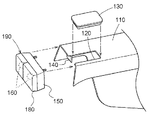
他方、ハウス内作業や果樹園で作業を行うロプスフレームなし仕様の農作業機として、例えば図9に示されている構造のものが提案され、実施されている。
即ち、後輪フェンダー110の後端部上面に形成した切欠き部120を覆うフェンダーテールカバー130を用意するとともに、ランプステー140に、樹脂製のランプフォルダ150、テールランプを兼ねたストップランプやバックランプ及びハザードランプを兼ねる方向指示器等のランプ類160、樹脂製のテールランプカバー180等で構成されたランプユニット190を固定した構造のものが実施されている。上記ロプスフレームなし仕様の農作業機をロプスフレーム装着仕様とする場合は、フェンダーテールカバー130を無くして、フェンダーテールカバー130を取り去ったときに形成される空間にロプスフレームを通すことが予定されているものである。
That is, a
図9の構造のロプスフレームなし仕様では、ロプスフレームが通る空間をフェンダーテールカバー130で閉塞するものであり、ロプスフレームを挿通する切欠き部が存在しないロプスフレームなし専用の仕様のものと比べて強度的に劣る。
本発明は、後部フェンダー構造をロプスフレームなし仕様のものとロプスフレーム装着仕様のものとが兼用できる形状としながら、ロプスフレームなし仕様の後部フェンダーの強度が低下しないようにすることにある。
In the specification without the rops frame in the structure of FIG. 9, the space through which the rops frame passes is blocked by the
An object of the present invention is to prevent the strength of a rear fender without a rops frame from being lowered while the rear fender structure has a shape that can be used for both a specification without a rops frame and a specification with a rops frame.
本第1の発明の構成は、左右の後輪フェンダーの後端部に後向きに開口した切欠き部を設け、後輪フェンダーの下方の車体固定部から立設した支柱部を切欠き部に入り込ませて運転部の上方に架設されるロプスフレームを設けるとともに切欠き部の後向き開口部を閉塞するようにしたロプスフレーム装着仕様と、ロプスフレームを除去した状態で切欠き部全体を閉塞するようにしたロプスフレームなし仕様とに仕様変更可能に構成してある農作業機であって、ロプスフレームなし仕様において、後輪フェンダーに、その後端後方側より後輪フェンダーの内面側に嵌合して切欠き部全体を閉塞するフォルダを装着するとともに、このフォルダを介してランプユニット又はレフレクターを後輪フェンダーに取付けるように構成した点にある。 In the configuration of the first aspect of the invention, a notch portion opened rearward is provided at the rear end portion of the left and right rear wheel fenders, and a column portion erected from a vehicle body fixing portion below the rear wheel fender enters the notch portion. The Lops frame is installed so as to block the rear opening of the notch, and the entire notch is closed with the Lops frame removed. It is a farm work machine configured to be able to change specifications to the specification without the rops frame, and in the specification without the rops frame, the rear wheel fender is fitted to the inner surface side of the rear wheel fender from the rear side of the rear end and is notched. A folder that closes the entire part is attached, and a lamp unit or a reflector is attached to the rear wheel fender via this folder.
本第1発明によると、ロプスフレームなし仕様において、後輪フェンダーに、その後端後方側より後輪フェンダーの内面側に嵌合して切欠き部全体を閉塞するフォルダを装着するとともに、このフォルダを介してランプユニットを後輪フェンダーに取付ける構成としてある。
例えばロプスフレーム装着仕様において、後輪フェンダーの切欠き部にロプスフレーム(支柱部)を入り込ませて、後輪フェンダーの後端部にランプユニット又はレフレクターを取付ける。ロプスフレームなし仕様にする場合は、ロプスフレーム(支柱部)を取付けず、フォルダを後輪フェンダーに取付ければ、フォルダにより後輪フェンダーの切欠き部を閉塞することができるのであり、フォルダにランプユニット又はレフレクターを取付けることができる。これにより、ロプスフレームなし仕様において、後輪フェンダー(切欠き部)に変更を施すことなく、後輪フェンダーの後端部にランプユニット又はレフレクターを取付けることができるのであり、ロプスフレーム装着仕様とロプスフレームなし仕様とで、共通したフェンダー形状のものが使用できる。
According to the first aspect of the present invention, in the specification without the lops frame, the rear wheel fender is fitted with a folder that fits to the inner surface side of the rear wheel fender from the rear end rear side and closes the entire notch, and this folder is attached to the rear wheel fender. The lamp unit is attached to the rear wheel fender.
For example, in the specification with the LOP's frame, the LOP's frame (support) is inserted into the notch of the rear wheel fender, and the lamp unit or reflector is attached to the rear end of the rear wheel fender. When the specification without a rops frame is used, the notch part of the rear wheel fender can be closed by the folder if the folder is attached to the rear wheel fender without attaching the rops frame (post). A unit or reflector can be attached. This allows the lamp unit or reflector to be attached to the rear end of the rear wheel fender without changing the rear wheel fender (notch) in the specification without the Lobs frame. The same fender shape can be used with the frameless specification.
ロプスフレームなし仕様において、ランプユニット又はレフレクターを取付けるフォルダを、ロプスフレーム装着仕様においてロプスフレームを挿通させる切欠き部を閉塞する部材に兼用してあるので、後部フェンダーをロプスフレーム装着仕様のものとロプスフレームなし仕様のものと切欠き部を設けた同じ形状のものを採用しながら、フォルダによって切欠き部全体を閉塞でき、しかもフォルダを後輪フェンダーの内面に嵌合して切欠き部全体を閉塞するように構成してあるので、フォルダにより切欠き部を有する後輪フェンダーを補強することができ、ロプスフレーム挿通用の切欠き部を形成していない専用のロプスフレームなし仕様のものと比べて強度を低下させないで、後部フェンダーをロプスフレーム装着仕様のものとロプスフレームなし仕様のものとに兼用できる利点がある。
殊に、ロプスフレーム装着仕様のものが圧倒的に多い場合において、ロプスフレームなし仕様のものを安価に製造できる利点がある。
In the specification without a rops frame, the folder to which the lamp unit or reflector is attached is also used as a member that closes the notch through which the rops frame is inserted in the specification with the rops frame. While adopting the same shape with a notch and a frame-less specification, the entire notch can be closed by the folder, and the entire notch is closed by fitting the folder to the inner surface of the rear wheel fender. The rear wheel fender that has a notch can be reinforced by a folder, compared to a dedicated rops frame-less specification that does not have a notch for inserting a rops frame. Without lowering the strength, the rear fender and the Lobs frame There is an advantage that can be shared and those of no over-time specification.
In particular, when there is an overwhelmingly large number of specs equipped with a lops frame, there is an advantage that a model without a lops frame can be manufactured at low cost.
又、ランプユニット又はレフレクターを取付けるフォルダとは別に切欠き部を閉塞する部材を設ける必要がなく、フォルダで切欠き部を閉塞するようにしてあるので、ロプスフレームなし仕様にするのに、強度的に丈夫なものにできながらも部品点数を増加することもなく、仕様変更をすることができた。
即ち、本第1発明においては、ランプユニットの取付け用のフォルダで後輪フェンダーの切欠き部を閉塞するようにしてあるので、部品点数並びに取付け手間も増大させることがないので、生産性を低下させることもなく製作できる利点がある。
In addition, it is not necessary to provide a member that closes the notch separately from the folder to which the lamp unit or reflector is attached, and the notch is closed by the folder. It was possible to change the specifications without increasing the number of parts, although it could be made more durable.
That is, in the first invention, since the notch portion of the rear wheel fender is closed with the lamp unit mounting folder, the number of parts and the mounting effort are not increased, so the productivity is reduced. There is an advantage that it can be manufactured without making it.
本第2発明は、第1発明の構成において、前記フォルダを後輪フェンダーの内面形状に沿った形状、又は略沿った形状で後輪フェンダーの内面側に装着してある。 According to the second aspect of the present invention, in the configuration of the first aspect, the folder is mounted on the inner surface side of the rear wheel fender in a shape along or substantially along the inner surface shape of the rear wheel fender.
本第2発明によると、フォルダを後輪フェンダーの内面形状に沿った形状、又は略沿った形状にしてあるので、フォルダを後輪フェンダーの内面に装着した状態で、フォルダ部分が後輪フェンダーとで二重構造となり、フェンダーの補強に対してより効果的に作用し、後輪フェンダーの補強に役立つ。 According to the second aspect of the present invention, since the folder is shaped along or substantially along the inner surface shape of the rear wheel fender, the folder portion is attached to the inner surface of the rear wheel fender, It becomes a double structure, works more effectively for reinforcing the fender, and helps to strengthen the rear wheel fender.
本第3発明は、第1発明または第2発明の構成において、前記フォルダにライセンスプレートの取付け部を一体に備えた点にある。 According to the third aspect of the present invention, in the configuration of the first aspect or the second aspect of the present invention, a mounting portion for a license plate is integrally provided in the folder.
本第3発明によると、ランプユニット及びライセンスプレートを取り付けるのに、部品点数及び取り付け工数の削減をすることができた。 According to the third invention, it is possible to reduce the number of parts and the number of mounting steps for mounting the lamp unit and the license plate.
以下、本発明の実施例を図面に基づいて説明する。
図1は、本発明の実施例に係るトラクタの全体側面図である。この図に示すように、本発明の実施例に係るトラクタは、左右一対の操向操作および駆動自在な前輪1,1と、左右一対の駆動自在な後輪2,2と、車体前部に設けたエンジン3と、ステアリングホィール4および運転座席5が装備された運転部6と、運転座席5の後側近くに位置したロプスフレーム7とを有した自走車体を備え、かつ、自走車体の車体フレームの後部を構成するミッションケース9に支持されたリンク機構10と、前記ミッションケース9の後部に設けた動力取り出し軸11とを備えている。リンク機構10は、ミッションケース9の上部の両横側に上下に揺動操作自在に支持されたリフトアーム12と、ミッションケース9の下部の両横側に上下揺動自在に支持されたロワーリンク13と、左右のリフトアーム12と左右のロワーリンク13とを連結する左右のリフトロッド14とを備えている。
このトラクタは、車体後部に前記リンク機構10によってロータリ耕耘装置(図示せず)を昇降操作自在に連結し、動力を動力取り出し軸11からロータリ耕耘装置に伝達するように構成して乗用型耕耘機を構成するなど、車体後部に各種の作業装置を昇降操作および駆動自在に連結して、各種の乗用型作業機を構成する。
Embodiments of the present invention will be described below with reference to the drawings.
FIG. 1 is an overall side view of a tractor according to an embodiment of the present invention. As shown in the figure, the tractor according to the embodiment of the present invention includes a pair of left and right steering operations and driveable front wheels 1 and 1, a pair of left and right driveable
This tractor is configured such that a rotary tiller (not shown) is connected to the rear of the vehicle body by the
エンジンボンネット41は、左右一対の横ボンネット42、両横ボンネット42,42の前方に位置するフロントグリル43、前記横ボンネット42やフロントグリル43の上方に位置する上ボンネット44を備えて構成してある。
The
上ボンネット44は、車体前後方向視で門形のフレームで成る後部ボンネット部53に車体横向きの軸芯まわりで上下に揺動自在に連結しており、横ボンネット42やフロントグリル43から上方に離間して上方を開放するように開き状態になり、下降側に揺動操作することにより、横ボンネット42やフロントグリル43の上端付近まで下降してエンジン3の上方を覆う閉じ状態になる。
The
上ボンネット44を閉じた場合、図3の如く上ボンネット44の前端側の内部に設けた閉じフック46により上ボンネット44を閉じ状態にロックする。閉じフック46は上ボンネット44の左右の側板部分に渡って架設したステー47に支持される。上ボンネット44の前端部には左右のヘッドライト48がビス45止めして装着されている。ヘッドライト48を支持する上ボンネット44の下部部分を構成する板金製のヘッドライトステー49は、上ボンネット本体50に対して分離でき、上ボンネット本体50の前端の左右中間部51とステー47の左右箇所にビス45止めできるように構成されている。ヘッドライト48は、ヘッドライトステー49を上ボンネット本体50に装着した状態で、ステー47と図示しないステー上枠とにビス45止めできるようになっている。
上ボンネット44を上ボンネット本体50とヘッドライトステー49とに分けて製作するようにしてあるので、上ボンネット本体50前部の形状を形成し易い簡素な形状に構成できるとともに、ヘッドライトステー49を板金のプレス又は折り曲げ加工で安価に製作することができる。これにより、例えば上ボンネット本体50前部を樹脂製の部材で覆うように構成した場合に比べ、金型費用等を節約できる。
When the
Since the
フロントスモールランプやハザードランプを兼ねる方向指示器を設けたフロントランプユニット52は、後部ボンネット部53の左右の横ボンネット部分54にステー55を介して取り付けられている。
A
ステー55は、一枚板状の板金製の板56に、図6に示すように切込み57を形成するとともに、この板56に、フロントランプユニット52を構成するランプ類の配線を通す孔58,59と、ステー55を横ボンネット部分54に取り付けるための取付け孔60,61と、フロントランプユニット52の取付け孔62,63とをキリ穴加工や打抜き加工で形成し、二点鎖線で示す折り曲げ線64,65に沿って、図5の斜視図に示すような形状に折り曲げ、傾斜上片66の下面側内端縁と縦側片67の外面とを隅肉溶接することにより一体的に製作する。
フロントランプユニット52の取付け用のステー55を上記のように板金を切り抜いて折り曲げ加工し、シンプルなワンビードの溶接により製作することで、簡単な構造で容易に製作できながら強度のあるステー55とすることができる。
The
The
図1、図2に示すように、ロプスフレーム7は、鋼管材からなる門形の支柱部15と基部16とで構成し、基部16をミッションケース9に締め付け固定してある。ロプスフレーム7を取付けた状態、又は取付けていない状態とすることにより、ロプスフレーム7を装着しないロプスフレームなし仕様と、ロプスフレーム7を装着したロプスフレーム装着仕様とに仕様変更できるようにしてある。
即ち、ロプスフレームなし仕様では、ロプスフレーム7を製造段階から装着していないが、ロプスフレーム装着仕様では、ロプスフレーム7を製造段階から装着するようにしてある。
As shown in FIGS. 1 and 2, the
That is, in the specification without the rops frame, the
図7に示すように、左右の後輪フェンダー24の後端部は、夫々正面視下向きコの字状に形成されているとともに、後向きに開口した切欠き部25を形成してあり、この切欠き部25内を通るようにロプスフレーム7を配設してある。
As shown in FIG. 7, the rear end portions of the left and right
〔ロプスフレーム装着仕様〕
図7に示すように、ロプスフレーム装着仕様においては、ランプユニット28のテールランプカバー38をランプフォルダ36から外した状態で、ランプフォルダ36を後輪フェンダー24の後端から装着して後輪フェンダー24の内側に付設した取付け用ピース23にビス止めし、後輪フェンダー24にランプフォルダ36を固定した後、テールランプカバー38を被せる。このようにランプユニット28の取付けにより後輪フェンダー24の後端部に形成されている切欠き部25の後向き開口部26が閉塞される。
[Lops frame wearing specifications]
As shown in FIG. 7, in the lops frame mounting specification, with the
前記ランプユニット28は、反射鏡(図示せず)を背面に設けたランプフォルダ36に、テールランプと兼用のストップランプ、バックランプ及びハザードランプ兼用の方向指示器等のランプ類37を取付けるとともに樹脂製のテールランプカバー38を嵌合してランプ類37を覆うことによって構成してある。
The
〔ロプスフレームなし仕様〕
図8に示すように、ロプスフレームなし仕様では、工場出荷段階からロプスフレーム7が取り付けられておらず、切欠き部25を閉塞するとともにランプユニット28(ロプスフレーム装着仕様とは異なる形状)を装着するための板金製のフォルダ27を備えている。
すなわち、ロプスフレームなし仕様においては、後輪フェンダー24にロプスフレーム7を通すために形成されている切欠き部25を閉塞できるフォルダ27を、後輪フェンダー24の後端から装着して後輪フェンダー24にボルト止めする。フォルダ27の下面には、ランプユニット28取付け用のボルト29を挿通する取付け孔30を形成した取付け部31を設けてある。ライセンスプレート32には、ボルト29を挿通する取付け孔33を形成した取付け部34を設けてある。これによりランプユニット28に設けたボルト29をライセンスプレート32に設けた取付け孔33とフォルダ27に設けた取付け孔30とに挿通してランプユニット28をライセンスプレート32とともにフォルダ27に取付けられるように構成してある。ライセンスプレート32には、ライセンスランプ40をボルト止めしてある。
[Lops frameless specification]
As shown in FIG. 8, in the specification without the lops frame, the
That is, in the specification without the lops frame, a
従って、ロプスフレームなし仕様においては、フォルダ27を後輪フェンダー24の後端から装着した状態では、後輪フェンダー24の後端部に形成されている切欠き部25はその全体がフォルダ27の上面によって閉塞されることとなる。ランプユニット28及びライセンスプレート32はボルト止めによりフォルダ27に取付けられる。
Therefore, in the specification without the lops frame, when the
フォルダ27は、左右対称に形成してあり、図8に図示している右側のフォルダ27を取付ける場合は、後輪フェンダー24の上面に形成したボルト孔24aと、フォルダ27に形成した左右のボルト孔27a、27bのうちの左側のボルト孔27aとにボルト69を挿通してフォルダ27をフェンダー24に固定する。
The
〔別実施の形態〕
発明を実施するための最良の形態では、フォルダ27の上面及び左右側面は後輪フェンダー24の上面及び左右側面の内面に沿った形状にしてあるが、フォルダ27の外形がフォルダ27と全く同じ形状でなくてもフォルダ27の上面及び左右側面が後輪フェンダー24の上面及び左右側面の内面に装着できる程度に略沿った形状であってもよいし、又、後輪フェンダー24の形状と全く異なった形状であってもよい。
[Another embodiment]
In the best mode for carrying out the invention, the upper surface and the left and right side surfaces of the
ロプスフレーム装着仕様及びロプスフレームなし仕様において、ランプユニット28に代えて、レフレクター(図示せず)後輪フェンダー24(フォルダ27)に取付けるように構成してもよい。ロプスフレーム装着仕様及びロプスフレームなし仕様において、同じ形状(仕様)のランプユニット28を後輪フェンダー24(フォルダ27)に取付けるように構成してもよい。
Instead of the
発明を実施するための最良の形態では、ロプスフレーム装着仕様では、ロプスフレーム7の基部16をミッションケース9の外面に締め付け固定した例を示したが、ミッションケース9に取付け用ブラケットを固定し、この取付け用ブラケットを介して、ロプスフレーム7の基部16をボルトナットで着脱自在に固定してもよい。ロプスフレーム7の基部を直接固定するミッションケース9や前記取付け用ブラケットを車体固定部と総称する。
In the best mode for carrying out the invention, an example in which the
6 運転部
7 ロプスフレーム
9 車体固定部(ミッションケース)
15 支柱部
24 後輪フェンダー
25 切欠き部
26 開口部
27 フォルダ
28 ランプユニット
31 取付け部
32 ライセンスプレート
6 Driving
15 Supporting
Claims (3)
ロプスフレームなし仕様において、前記後輪フェンダーに、その後端後方側より後輪フェンダーの内面側に嵌合して前記切欠き部全体を閉塞するフォルダを装着するとともに、このフォルダを介してランプユニット又はレフレクターを後輪フェンダーに取付けるように構成してある農作業機。 The rear end of the left and right rear fenders is provided with a notch that opens rearward, and a column that is erected from the body fixing part below the rear wheel fender is inserted into the notch and is installed above the driving part. A lops frame mounting specification in which the rear opening of the notch is closed and a no-rops frame specification in which the entire notch is closed with the rops frame removed is provided. Agricultural machines configured to allow specification changes to
In the specification without a rops frame, the rear wheel fender is fitted with a folder that fits to the inner surface side of the rear wheel fender from the rear end rear side and closes the entire notch, and the lamp unit or Agricultural work machine configured to attach the reflector to the rear fender.
Priority Applications (1)
| Application Number | Priority Date | Filing Date | Title |
|---|---|---|---|
| JP2008236675A JP4981775B2 (en) | 2008-09-16 | 2008-09-16 | Agricultural machine |
Applications Claiming Priority (1)
| Application Number | Priority Date | Filing Date | Title |
|---|---|---|---|
| JP2008236675A JP4981775B2 (en) | 2008-09-16 | 2008-09-16 | Agricultural machine |
Publications (2)
| Publication Number | Publication Date |
|---|---|
| JP2010069925A JP2010069925A (en) | 2010-04-02 |
| JP4981775B2 true JP4981775B2 (en) | 2012-07-25 |
Family
ID=42202123
Family Applications (1)
| Application Number | Title | Priority Date | Filing Date |
|---|---|---|---|
| JP2008236675A Active JP4981775B2 (en) | 2008-09-16 | 2008-09-16 | Agricultural machine |
Country Status (1)
| Country | Link |
|---|---|
| JP (1) | JP4981775B2 (en) |
Cited By (1)
| Publication number | Priority date | Publication date | Assignee | Title |
|---|---|---|---|---|
| EP4052963A1 (en) * | 2021-03-05 | 2022-09-07 | CLAAS Tractor S.A.S. | Set of parts for a front light module |
Families Citing this family (3)
| Publication number | Priority date | Publication date | Assignee | Title |
|---|---|---|---|---|
| JP2013136359A (en) * | 2011-12-28 | 2013-07-11 | Kubota Corp | Tractor |
| JP6964011B2 (en) * | 2018-02-08 | 2021-11-10 | 新明和工業株式会社 | Suction device and its manufacturing method |
| JP7097290B2 (en) * | 2018-12-27 | 2022-07-07 | 株式会社クボタ | Work vehicle |
Family Cites Families (3)
| Publication number | Priority date | Publication date | Assignee | Title |
|---|---|---|---|---|
| JPH0251951U (en) * | 1988-10-07 | 1990-04-13 | ||
| JPH0256777U (en) * | 1989-10-21 | 1990-04-24 | ||
| JP3187651B2 (en) * | 1994-06-06 | 2001-07-11 | 株式会社クボタ | Overturn protection frame structure of agricultural work machine |
-
2008
- 2008-09-16 JP JP2008236675A patent/JP4981775B2/en active Active
Cited By (1)
| Publication number | Priority date | Publication date | Assignee | Title |
|---|---|---|---|---|
| EP4052963A1 (en) * | 2021-03-05 | 2022-09-07 | CLAAS Tractor S.A.S. | Set of parts for a front light module |
Also Published As
| Publication number | Publication date |
|---|---|
| JP2010069925A (en) | 2010-04-02 |
Similar Documents
| Publication | Publication Date | Title |
|---|---|---|
| US7252170B2 (en) | Structure for disposing fuel tank for straddle-type vehicle | |
| WO2016189940A1 (en) | Tractor | |
| US9061718B2 (en) | Working vehicle assembly | |
| JP4981775B2 (en) | Agricultural machine | |
| EP3378751A1 (en) | Rear fender supporting structure of saddle-type vehicle | |
| JP4632159B2 (en) | Vehicle hood hinge and vehicle front structure including the same | |
| JP4546886B2 (en) | Tractor power structure | |
| JP4624866B2 (en) | Motorcycle | |
| US8579364B2 (en) | Work vehicle | |
| JP5459017B2 (en) | Work vehicle | |
| JP6329878B2 (en) | Work vehicle | |
| JP5356103B2 (en) | Bonnet support structure for traveling vehicles | |
| KR102032916B1 (en) | A Hinge assembly for a bonnet open and shut of a agriculture vehicle and Hinge construction of a agriculture vehicle contains the same | |
| JP4689071B2 (en) | Bonnet structure of tractor | |
| JP4372045B2 (en) | Body frame of work vehicle | |
| EP3290269B1 (en) | Tractor | |
| JP2007076560A (en) | Tractor front supporting element | |
| JP4899432B2 (en) | Vehicle hood hinge structure | |
| JP4877760B2 (en) | Assist bar with lamp for work vehicle | |
| JP4621079B2 (en) | Walking type work machine | |
| JP6499012B2 (en) | Tractor | |
| JP3187651B2 (en) | Overturn protection frame structure of agricultural work machine | |
| JP4598571B2 (en) | Passenger rice transplanter | |
| JP5480611B2 (en) | Work vehicle | |
| JP2000085615A (en) | Structure of safety frame support portion for tractor |
Legal Events
| Date | Code | Title | Description |
|---|---|---|---|
| A621 | Written request for application examination |
Free format text: JAPANESE INTERMEDIATE CODE: A621 Effective date: 20100927 |
|
| A977 | Report on retrieval |
Free format text: JAPANESE INTERMEDIATE CODE: A971007 Effective date: 20120316 |
|
| TRDD | Decision of grant or rejection written | ||
| A01 | Written decision to grant a patent or to grant a registration (utility model) |
Free format text: JAPANESE INTERMEDIATE CODE: A01 Effective date: 20120322 |
|
| A01 | Written decision to grant a patent or to grant a registration (utility model) |
Free format text: JAPANESE INTERMEDIATE CODE: A01 |
|
| A61 | First payment of annual fees (during grant procedure) |
Free format text: JAPANESE INTERMEDIATE CODE: A61 Effective date: 20120420 |
|
| FPAY | Renewal fee payment (event date is renewal date of database) |
Free format text: PAYMENT UNTIL: 20150427 Year of fee payment: 3 |
|
| R150 | Certificate of patent or registration of utility model |
Ref document number: 4981775 Country of ref document: JP Free format text: JAPANESE INTERMEDIATE CODE: R150 Free format text: JAPANESE INTERMEDIATE CODE: R150 |