JP4981587B2 - Coil bobbin - Google Patents
Coil bobbin Download PDFInfo
- Publication number
- JP4981587B2 JP4981587B2 JP2007222553A JP2007222553A JP4981587B2 JP 4981587 B2 JP4981587 B2 JP 4981587B2 JP 2007222553 A JP2007222553 A JP 2007222553A JP 2007222553 A JP2007222553 A JP 2007222553A JP 4981587 B2 JP4981587 B2 JP 4981587B2
- Authority
- JP
- Japan
- Prior art keywords
- coil wire
- coil
- winding
- guide
- wire
- Prior art date
- Legal status (The legal status is an assumption and is not a legal conclusion. Google has not performed a legal analysis and makes no representation as to the accuracy of the status listed.)
- Active
Links
Images


Description
本発明は、コイルワイヤを巻回してソレノイドコイル等のコイル部品を得るためのコイルボビンに関する。 The present invention relates to a coil bobbin for winding a coil wire to obtain a coil component such as a solenoid coil.
コイル部品の一種であるソレノイドコイルが、金属シャフトやバルブなどを移動/開閉制御するための装置として従来一般的に用いられている。近年では特に自動車用途として、ABS(アンチロックブレーキシステム)やAT(オートマチックトランスミッション)としての需要が高まっている。
これらの自動車用途のソレノイドコイルは、耐水・耐湿・防塵等の性能を高めることによって過酷な使用環境に対応可能であることが求められる。これを達成する技術としては、例えば下記特許文献1に記載のように、樹脂製のコイルボビンに巻線コイルを巻回してなる内部コイル(ボビン内包)を、外装樹脂部材(絶縁封止部材)で封止成型したソレノイドコイルが知られている。
A solenoid coil, which is a kind of coil component, has been generally used as a device for moving / opening / closing controlling a metal shaft or a valve. In recent years, demand for ABS (anti-lock brake system) and AT (automatic transmission) has been increasing particularly for automobile applications.
These automotive use solenoid coils are required to be able to cope with harsh usage environments by improving performance such as water resistance, moisture resistance and dust resistance. As a technique for achieving this, for example, as described in Patent Document 1 below, an internal coil (bobbin inclusion) formed by winding a winding coil around a resin coil bobbin is used as an exterior resin member (insulation sealing member). Sealed solenoid coils are known.
また、ABSやATなど、刻々と変化する制御条件に適応しつつ金属シャフトなどを迅速かつ的確に移動/開閉制御するにあたっては、大きな電磁力を発生可能に構成することが望ましく、そのためにはソレノイドコイルの構成要素の一つである巻線コイルを可能な限り整列巻回させ、コイルボビンの巻芯部に対するコイルワイヤの占有率(線積率)を高める必要がある。
これを達成する例としては、例えば下記特許文献2に記載のように、巻芯部(巻回部)の構成面に巻線ガイド(ガイド突起)を設け、この巻線ガイドに沿ってコイルワイヤを巻回することによって整列巻回を可能としたコイルボビンが知られている。
なお、このコイルボビンでは、構成面の周方向に伸びる巻線ガイドを非環状とし、巻線ガイドの非形成部を平坦に形成して巻回列切換部とすることによって、コイルワイヤの巻回をnターン目(nは0以上の整数)からn+1ターン目に切り換えることを容易にしている。
In addition, it is desirable to be able to generate a large electromagnetic force when moving / opening / closing the metal shaft quickly and accurately while adapting to ever-changing control conditions such as ABS and AT. The winding coil which is one of the constituent elements of the coil needs to be aligned and wound as much as possible to increase the occupancy (line product ratio) of the coil wire with respect to the core portion of the coil bobbin.
As an example for achieving this, as described in Patent Document 2 below, for example, a winding guide (guide protrusion) is provided on the constituent surface of the core portion (winding portion), and a coil wire is provided along the winding guide. 2. Description of the Related Art Coil bobbins that can be aligned and wound by winding are known.
In this coil bobbin, the winding guide extending in the circumferential direction of the constituent surface is made non-annular, and the winding guide non-formation portion is formed flat to form a winding row switching portion, thereby winding the coil wire. Switching from the nth turn (n is an integer of 0 or more) to the (n + 1) th turn is facilitated.
しかし、上記特許文献2に記載のコイルボビンにコイルワイヤを巻回してなる内部コイルの表面を上記特許文献1の如く外装樹脂部材で封止成型しようとすると、(i)溶融した外装樹脂部材(溶融樹脂)が内部コイル(巻回コイル)を巻軸方向に押圧変形させることでコイルワイヤに引張応力を与える流れ込み、および(ii)該樹脂が巻芯部の構成面を伝って巻回コイルの内側に流れ込むことで、成型時またはコイル部品の熱サイクル下での使用時にコイルワイヤに熱応力を与える挿込みによって、コイルワイヤが断線するという重大な不具合が発生する虞がある。 However, when the surface of the internal coil formed by winding a coil wire around the coil bobbin described in Patent Document 2 is sealed with an exterior resin member as in Patent Document 1, (i) a molten exterior resin member (molten) The resin) flows into the coil wire by pressing and deforming the internal coil (winding coil) in the winding axis direction, and (ii) the resin travels along the surface of the winding core to form the inside of the winding coil. By flowing into the coil wire, there is a possibility that a serious problem that the coil wire is disconnected due to insertion of applying thermal stress to the coil wire during molding or when the coil component is used under a thermal cycle may occur.
上記不具合の発生原因について、図9を用いて説明する。図9は、上記特許文献2にかかるコイルボビン110を、図示しない外型(金型)に封入し、溶融樹脂160を射出して巻回コイル145を封止する状態を表す部分縦断面模式図である。コイルボビン110は、対向するフランジ部114aおよびフランジ部114bと、その間に形成された構成面116とを備えている。巻回コイル145は、コイルワイヤ導入溝120およびコイルワイヤ案内部122を通じて構成面116に案内されたコイルワイヤ140を、所定のテンションを負荷した状態で構成面116に巻回したものである。
上記(i)の流れ込みは以下のようにして生じる。すなわち溶融樹脂160は、フランジ部114aの上面側より高圧で射出されると、フランジ部114aに設けられたコイルワイヤ導入溝120およびコイルワイヤ案内部122を通じてコイルボビン110の巻回面である構成面116に流入し、図中短矢印のように巻回コイル145の上端面(フランジ部114a近接側端面)を押し下げていく。すると、所定のテンションをもってコイルワイヤ案内部122より構成面116に引き込まれた引込線141は溶融樹脂160によって図中下方への引張応力を受けて損傷し、または破断する。
The cause of the occurrence of the above problem will be described with reference to FIG. FIG. 9 is a partial vertical cross-sectional schematic diagram showing a state in which the
The inflow of (i) occurs as follows. That is, when the
一方、上記(ii)の挿込みについては、上記特許文献2にかかるコイルボビン110の場合、コイルボビンのフランジ部に形成された端末ガイド溝(1a9)の先端が巻回列切換部(1c1)に位置していることから、金型内に射出された溶融樹脂がフランジ部から端末ガイド溝を介して巻芯部に流れ込み、巻回されたコイルワイヤの最下層と構成面との間を図中長矢印のように巻軸方向に浸入して(挿込んで)いくことにより発生する。
内部コイルに浸入する溶融樹脂は、特に端末ガイド溝から巻芯部への引き込み位置にある引込線141に対して射出時の高圧を付与し、これに引張方向の荷重を与えて断線させる要因となる。
On the other hand, regarding the insertion of (ii) above, in the case of the
The molten resin that penetrates into the internal coil gives a high pressure at the time of injection to the lead-in
また、巻回されたコイルワイヤの内部に大量の溶融樹脂が、特に巻軸方向の中途位置まで浸入したコイル部品を冷却して外装樹脂部材を硬化させた場合、これを熱サイクル下で繰り返し使用すると、一般に線膨張係数の大きな外装樹脂部材の熱膨張および熱収縮による熱応力の負荷により、やはりコイルワイヤの断線を招く要因となる。
この原因は以下と推察される。すなわち、内部コイルの外表面全体を被覆する外装樹脂部材は、熱サイクルによって熱膨張/熱収縮を繰り返したとしても、コイルワイヤに対しては主として巻芯部の径方向に押付荷重を付与するばかりであってコイルワイヤ(引込線141または巻回コイル145)を引張破断させる虞は少ない。これに対し、コイルワイヤの内部に浸入して特に巻軸方向の中途位置に自由端をもつ外装樹脂部材は、熱変形によって巻軸方向に膨張/収縮を繰り返すことから、上記引き込み位置にあるコイルワイヤ(引込線141)に対して引張方向の荷重を負荷することとなる。かかる膨張/収縮は、コイルワイヤ内部への溶融樹脂の浸入(挿込み)量が多いほど顕著となる。特に上述に起因して溶融樹脂160の射出時に引込線141が損傷を受けると、熱サイクル下での熱応力によってこれが容易に破断する虞がある。
Also, when a large amount of molten resin enters the coiled coil wire, especially when coil parts that have entered the middle of the winding axis are cooled and the exterior resin member is cured, this is repeatedly used under a thermal cycle. As a result, thermal stress caused by thermal expansion and contraction of the exterior resin member having a large linear expansion coefficient generally causes a breakage of the coil wire.
The reason is presumed as follows. In other words, the exterior resin member that covers the entire outer surface of the internal coil only applies a pressing load to the coil wire in the radial direction of the core even if the thermal expansion / thermal contraction is repeated by the thermal cycle. And there is little possibility that the coil wire (the lead-in
なお上記課題は、ソレノイドコイルに限らず、外装樹脂部材で封止成型される各種のコイル部品に共通して発生する問題である。
本発明は、コイルワイヤを巻芯部に整列巻回することのできるコイルボビンであって、巻回されたコイルワイヤに対する溶融樹脂の上記流れ込みおよび挿込みを抑制し、成型時や熱サイクル下での使用時にコイルワイヤの断線を防止することのできるコイルボビンを提供することを目的とする。
In addition, the said subject is a problem which generate | occur | produces not only in a solenoid coil but in common with the various coil components seal-molded with an exterior resin member.
The present invention is a coil bobbin capable of aligning and winding a coil wire around a winding core part, which suppresses the above-described flow and insertion of molten resin into the wound coil wire, and can be used at the time of molding or under a heat cycle. It aims at providing the coil bobbin which can prevent a disconnection of a coil wire at the time of use.
本発明は、フランジ部に形成されたコイルワイヤ案内部と巻芯部の構成面との境界位置を通る軸線を跨いで巻線ガイドを形成することにより、コイルワイヤを整列巻回するための当該巻線ガイドを、巻回コイルの変形を防止するストッパーとして、かつ溶融樹脂の挿込みに対する堤防として用いるという技術思想に基づいてなされたものである。 The present invention relates to a coil wire that is wound in an aligned manner by forming a winding guide across an axis passing through a boundary position between a coil wire guide portion formed on a flange portion and a constituent surface of a core portion. This is based on the technical idea that the winding guide is used as a stopper for preventing deformation of the winding coil and as a bank for insertion of molten resin.
すなわち本発明は、
(1)巻芯部と、前記巻芯部の巻軸方向の少なくとも一端に設けられたフランジ部とを備え、前記巻芯部の構成面に対しコイルワイヤを前記巻軸方向に沿って所望のターン数にて巻回するコイルボビンであって、前記フランジ部には、前記フランジ部の外周側から所定の深さで切り込み形成され、巻軸方向の前記一端側から巻芯部にむけてコイルワイヤを引き込むためのコイルワイヤ導入溝と、前記コイルワイヤ導入溝と連通し、該コイルワイヤ導入溝より前記巻芯部の構成面に向かって引き込まれたコイルワイヤを案内するためのコイルワイヤ案内部とが形成され、前記コイルワイヤ案内部は、前記コイルワイヤ導入溝と前記構成面とを結び、前記コイルワイヤを案内するガイド面と、前記コイルワイヤ導入溝と連通して形成され、案内されるコイルワイヤと前記フランジ部とが干渉しないようにするワイヤ逃げ部とを備え、前記巻芯部の構成面には、コイルワイヤの巻回方向に伸びて前記案内されたコイルワイヤを整列巻回するための非環状の巻線ガイドと、巻回されるコイルワイヤの巻回ターンを切り換えるためのガイド非形成部とが設けられるとともに、前記巻線ガイドは、前記フランジ部に最も近接するターンのコイルワイヤをガイドするための巻線ガイドが、前記コイルワイヤ案内部と前記巻芯部の構成面との境界位置を通る軸線よりも巻回方向に位置するように設けられ、前記フランジ部より数えて2ターン目以降のコイルワイヤをガイドするための巻線ガイドが、前記軸線を跨いで形成されていることを特徴とするコイルボビン;
(2)前記コイルワイヤ逃げ部が、前記フランジ部の裏面側に所定厚さで削成されて形成されている上記(1)記載のコイルボビン;
(3)前記巻線ガイドが、前記巻芯部の構成面に対して凸状に形成されている上記(1)又は(2)記載のコイルボビン;
(4)前記コイルワイヤ案内部が、前記コイルワイヤ導入溝と連通するとともに、巻軸直交方向の断面において、前記コイルワイヤ導入溝より前記巻芯部の構成面に向かう接線方向に形成されている上記(1)〜(3)のいずれかに記載のコイルボビン;
を要旨とする。
That is, the present invention
(1) A winding core portion and a flange portion provided at at least one end in the winding axis direction of the winding core portion, and a desired coil wire along the winding axis direction with respect to the constituent surface of the winding core portion. A coil bobbin that is wound by the number of turns, and is formed by cutting the flange portion at a predetermined depth from the outer peripheral side of the flange portion, toward the core portion from the one end side in the winding axis direction. A coil wire introduction groove for drawing the coil wire, a coil wire guide portion for communicating with the coil wire introduction groove, and for guiding the coil wire drawn from the coil wire introduction groove toward the constituent surface of the core portion, There is formed, the coil wire guide portion, the coil wire introduction groove and bear with the structure surface, a guide surface for guiding the coil wire is formed in communication with the coil wire introduction groove, the guide of That a wire escape portion of the coil wire and the flange portion does not interfere, the the structure surface of the core portion, the coil wire winding aligning the coil wire which is the guide extending in the direction winding A non-annular winding guide for switching and a guide non-forming portion for switching a winding turn of the coil wire to be wound are provided, and the winding guide has a turn closest to the flange portion. A winding guide for guiding the coil wire is provided so as to be positioned in a winding direction with respect to an axis passing through a boundary position between the coil wire guide portion and the constituent surface of the core portion, and counted from the flange portion. A coil bobbin, wherein a winding guide for guiding the coil wire after the second turn is formed across the axis ;
(2) The coil bobbin according to the above (1 ), wherein the coil wire relief portion is formed by cutting a predetermined thickness on the back surface side of the flange portion;
(3) The coil bobbin according to ( 1) or (2) , wherein the winding guide is formed in a convex shape with respect to the constituent surface of the core portion;
(4) The coil wire guide portion communicates with the coil wire introduction groove, and is formed in a tangential direction from the coil wire introduction groove toward the constituent surface of the core portion in a cross section perpendicular to the winding axis. The coil bobbin according to any one of ( 1) to (3) ;
Is the gist.
また本発明においてはさらに具体的な態様として、
(5)前記コイルワイヤ案内部と前記巻芯部の構成面とが前記境界位置において面一に構成されている上記(1)〜(4)のいずれかに記載のコイルボビン;
(6)前記コイルワイヤ案内部が前記フランジ部の巻芯部側に削成されている上記(1)〜(5)のいずれかに記載のコイルボビン;
(7)上記(1)〜(6)のいずれかに記載のコイルボビンと、
前記コイルワイヤ導入溝より巻芯部に引き込まれ、前記巻線ガイドに沿って前記巻芯部の構成面に一層または多層に巻回されたコイルワイヤと、
前記巻回されたコイルワイヤを封止する外装樹脂部材と、
を備えるコイル部品;
(8)前記フランジ部には、巻回されたコイルワイヤの終端を当該フランジ部より引き出すためのコイルワイヤ導出部が、前記コイルワイヤの最大巻径よりも径方向の外側に設けられている上記(7)に記載のコイル部品;
によっても上記本発明の目的を達成することができる。
In the present invention, as a more specific embodiment,
(5) The coil bobbin according to any one of (1) to (4) , wherein the coil wire guide portion and the surface of the core portion are flush with each other at the boundary position;
(6) The coil bobbin according to any one of (1) to (5) , wherein the coil wire guide portion is cut on a core portion side of the flange portion;
(7) The coil bobbin according to any one of (1) to (6 ) above,
A coil wire drawn into the core portion from the coil wire introduction groove and wound in one or more layers on the constituent surface of the core portion along the winding guide;
An exterior resin member for sealing the wound coil wire;
A coil component comprising:
(8) The said flange part is provided with the coil wire derivation | leading-out part for pulling out the terminal end of the wound coil wire from the said flange part in the outer side of radial direction rather than the maximum winding diameter of the said coil wire. (7) coil components;
The object of the present invention can also be achieved.
本発明のコイルボビンによれば、巻線ガイドに沿ってコイルワイヤを巻芯部に整列巻回させ、高い線積率の内部コイルを得ることができる。またコイルワイヤを巻回した本発明のコイルボビンを外装樹脂部材で封止成型するにあたっては、コイルワイヤ案内部と構成面との境界位置を通る軸線を跨いで巻線ガイドを設けたことによって、コイルワイヤ導入溝から流れ込んだ高圧の溶融樹脂によっても内部コイルが押圧変形することがなく、また該樹脂が内部コイルに浸入することを防止できる。これにより溶融樹脂による封止成型時に、および成型後に熱サイクル下で使用された場合も、本発明のコイルボビンによれば巻回されたコイルワイヤに過大な引張荷重が負荷されることがなく、したがってその断線の問題を解消することができる。 According to the coil bobbin of the present invention, a coil wire is aligned and wound around the winding core along the winding guide, and an internal coil having a high line area ratio can be obtained. When the coil bobbin of the present invention around which the coil wire is wound is sealed and molded with the exterior resin member, the coil guide is provided by straddling the axis passing through the boundary position between the coil wire guide portion and the component surface. The internal coil is not pressed and deformed by the high-pressure molten resin flowing from the wire introduction groove, and the resin can be prevented from entering the internal coil. As a result, even when used in a sealing molding with a molten resin and under a thermal cycle after molding, the coil bobbin of the present invention does not apply an excessive tensile load to the coiled coil wire. The disconnection problem can be solved.
以下、本発明のコイルボビンについて、図面を用いて具体的に説明する。
図1は本発明の第一実施形態にかかるコイルボビン10の斜視図であり、フランジ部14aに形成されたコイルワイヤ導入溝20を巻芯部12側から臨む正面下方斜視図である。
図2は、コイルワイヤ案内部22およびその近傍に関する本実施形態のコイルボビン10の部分拡大斜視図である。
図3は本実施形態のコイルボビン10の正面図、図4は同じく背面図である。
ただし図2においては、巻芯部12の構成面16とコイルワイヤ案内部22との境界位置221を通る軸線161を想像線にて図示している。また図3においては、コイルワイヤ導入溝20より巻芯部12側に引き込まれて構成面16に整列巻回されるコイルワイヤ40を想像線にて図示している。
Hereinafter, the coil bobbin of the present invention will be specifically described with reference to the drawings.
FIG. 1 is a perspective view of a
FIG. 2 is a partially enlarged perspective view of the
3 is a front view of the
However, in FIG. 2, the
本発明のコイルボビン10は、巻芯部12と、その巻軸方向(図3,4における上下方向)の少なくとも一端(同図上端)に設けられたフランジ部14aとを備え、巻芯部12の構成面16に対してコイルワイヤ40を所望のターン数にて巻軸方向に並べて整列巻回するものである。整列巻回したコイルワイヤ40を巻回コイル45と呼称する(図3参照)。本実施形態のコイルボビン10の場合、フランジ部14aの反対側(同図下端)に他のフランジ部14bを備えており、対向するフランジ部14a,14bの間にコイルワイヤ40が巻回可能である。
巻芯部12の横断面(巻軸方向に垂直に切った断面)形状は特に限定されるものではなく、本実施形態のコイルボビン10では巻芯部12を円筒状としている。したがって巻芯部12の内部には空芯部30が形成されて他の部材が挿通可能である。コイルボビン10にコイルワイヤ40を巻回してソレノイドコイルを構成した場合は、空芯部30にシャフトなどの可動鉄心を配置することができる。
The
The shape of the cross section (cross section cut perpendicularly to the winding axis direction) of the
巻芯部12の材料は特に限定されず、フェライトなどのセラミックス材料、鉄系などの金属材料、アモルファス金属材料、またはエンジニアリングプラスチックなどの樹脂材料を用いることができる。
The material of the
フランジ部14aには、巻軸方向について当該フランジ部14aの設けられた一端側から、すなわち当該フランジ部14aの先端側から、巻芯部12側にむけてコイルワイヤ40を引き込むためのコイルワイヤ導入溝20が形成されている。コイルワイヤ導入溝20は少なくとも巻回されるコイルワイヤ40よりも太幅であり、フランジ部14aの外周側から所定の深さで切り込み形成されている。
またフランジ部14aには、コイルワイヤ40の両端がそれぞれ接続される外部端子取付基部28a,28bが突出形成されている。外部端子取付基部28a,28bの形状および形成位置は特に限定されない。本実施形態の場合、外部端子取付基部28a,28bはフランジ部14aの周面上に設けられ、径方向に突出している。また本実施形態の場合、外部端子取付基部28a,28bには金属端子が挿入され、コイルワイヤ40の両端は金属端子に絡げられる。すなわちコイルワイヤ40は外部端子取付基部28a,28bに直接固定されても、本実施形態のように間接的に固定されてもよい。
これにより、図示しないコイル巻線装置に巻回された十分な長さのコイルワイヤ40の先端を外部端子取付基部28aに固定し、コイルワイヤ導入溝20の形成位置にてフランジ部14aを跨ぐことで、コイルワイヤ40にテンションをかけた状態でこれを巻芯部12側に引き込むことができる。
A coil wire is introduced into the
Further, external
Thereby, the front end of a sufficiently
フランジ部14aの裏面(巻芯部12側)には、コイルワイヤ導入溝20より引き込まれたコイルワイヤ40を巻芯部12の構成面16に向けて案内するコイルワイヤ案内部22が削成されている。
コイルワイヤ案内部22は、コイルワイヤ導入溝20と連通し、コイルワイヤ導入溝20より巻芯部12の構成面16に向かってコイルワイヤ40(引込線41:図3を参照)を滑らかに案内するものである。本発明においてコイルワイヤ案内部22とは特に、コイルワイヤ導入溝20と構成面16とを結びコイルワイヤ40を案内するガイド面222を意味する。コイルワイヤ案内部22はこのほか、案内されるコイルワイヤ40とフランジ部14aとが干渉しないよう、ガイド面222の近傍にコイルワイヤ導入溝20と連通して形成したワイヤ逃げ部223を備えている。
A coil
The coil
ただしコイルワイヤ案内部22は、本実施形態のようにフランジ部14aの裏面側(巻芯部12側)にワイヤ逃げ部223が所定厚さで削成されることによってガイド面222が形成されていてもよく、またはフランジ部14aの裏面よりコイルワイヤ案内部22が突出することによってガイド面222が形成されていてもよい。ただし、フランジ部14aの裏面上にコイルワイヤ案内部22を突出形成した場合、当該突出厚さについてはコイルワイヤ40を巻芯部12に巻回することが困難となるところ、本実施形態のようにフランジ部14aの厚みを利用してその内部にコイルワイヤ案内部22を掘り込み形成することにより、フランジ部14aの裏面の際位置までコイルワイヤ40を巻回することができ、巻芯部12に対する高い線積率を実現することができる。
However, the coil
コイルワイヤ導入溝20を介してコイルボビン10の巻軸方向に引き込まれた引込線41は、コイルワイヤ案内部22にガイドされて巻芯部12の周方向に向きが変えられ、図2,3に矢印にて示す巻回方向WDに向かって引き回されることとなる。
The lead-in
したがって本実施形態の場合、コイルワイヤ案内部22はコイルワイヤ導入溝20と連通するとともに、巻芯部12の横断面においてコイルワイヤ導入溝20より巻芯部12の構成面16に向かう接線方向に形成されている。より具体的には、コイルワイヤ導入溝20の最深位置(径方向について巻軸中心に最も近い位置)から構成面16に向けて巻回方向に下ろした接線と、ガイド面222とが、巻芯部12の横断面内において一致している。
Therefore, in the case of the present embodiment, the coil
図5は、図2に切断線を示すコイルボビン10のV−V断面図であり、フランジ部14aを裏面側から見た様子を表すものである。コイルワイヤ40の巻回方向WDを矢印で示す。巻回方向WDは図2と対応している。
FIG. 5 is a VV cross-sectional view of the
本実施形態の場合、コイルワイヤ案内部22を構成するガイド面222と構成面16とは境界位置221において接しており、コイルワイヤ導入溝20より引き込まれたコイルワイヤ40はテンションを保ったままガイド面222および構成面16にともに接触することができる。これにより、コイルボビン10にコイルワイヤ40を巻回した場合には、コイルワイヤ導入溝20より引き込まれるコイルワイヤ40とコイルワイヤ案内部22との間に隙間が形成されることがない。
このため、コイルボビン10にコイルワイヤ40を巻回してなる内部コイルを外型に封入し、溶融樹脂を射出することで外装樹脂部材にて封止成型するに際して、コイルワイヤ導入溝20より引き込まれるコイルワイヤ40に負荷される引張応力が低減される。これは、コイルワイヤ案内部22とコイルワイヤ40との間に隙間がないことによって、フランジ部14aの表面側から裏面側に向かってコイルワイヤ導入溝20を通じて流れ込んだ溶融樹脂がコイルワイヤ案内部22に向かって流れるにあたり、コイルワイヤ案内部22と密着したコイルワイヤ40は高粘性の溶融樹脂の境界層内にあるためである。これにより当該コイルワイヤ40と溶融樹脂との相対速度は小さく、したがってコイルワイヤ導入溝20より引き込まれたコイルワイヤ40には過大な引張応力が負荷されることがない。
なお本実施形態と異なり、コイルワイヤ案内部22が巻芯部12の横断面内で構成面16と接しておらずにコイルワイヤ案内部22とコイルワイヤ40との間に隙間が形成された場合は、当該隙間を溶融樹脂が通過しようとするため、コイルワイヤ40は溶融樹脂の主流内に位置することとなって溶融樹脂との相対速度が大きくなり、コイルワイヤ40が受ける引張荷重は過大となって破断の虞が生じる。
また、ガイド面222とコイルワイヤ40との間に隙間がないことにより、コイルワイヤ導入溝20より巻芯部12側に流れ込んだ溶融樹脂は、コイルワイヤ40を伝って、コイルワイヤ導入溝20から専らコイルワイヤ案内部22に向かって流れることとなり、コイルワイヤ導入溝20から直接に構成面16に至るものは微量となる。このため、巻回されたコイルワイヤ40の内部に対して、特にコイルワイヤ導入溝20からガイド非形成部26(後述)に直接至った溶融樹脂が巻軸方向に向かって挿し込むことが防止される。これにより、封止成型されたコイルボビン10を熱サイクル下で長期間使用した場合にも、内部コイルに挿し込んだ外装樹脂部材の熱膨張/熱収縮に起因するコイルワイヤ40の引張破断が生じることが防止される。
In the case of this embodiment, the
For this reason, a coil drawn from the coil
Unlike the present embodiment, when the
Further, since there is no gap between the
一方、本発明においては、コイルワイヤ導入溝20から巻芯部12側に引き込まれたコイルワイヤ40が構成面16に滑らかに案内されるものであれば、境界位置221においてコイルワイヤ案内部22と構成面16との間にコイルワイヤ40の直径を越える段差があっても、またはコイルワイヤ案内部22と構成面16とが境界位置221において面一に構成されていてもよい。ここでいう面一とは、両者の高さの差がコイルワイヤ40の直径以下であること、好ましくは境界位置221においてガイド面222または構成面16とコイルワイヤ40との間に実質的に隙間が形成されない状態をいうものである。
ただしコイルワイヤ案内部22と構成面16とを面一に構成することにより、コイルワイヤ案内部22に流れ込んだ溶融樹脂が、コイルワイヤ40と構成面16との隙間から巻芯部12側に容易に流れ込むことを防止し、射出成型時にコイルワイヤ40に負荷される引張応力を軽減することができる。
On the other hand, in the present invention, if the
However, by configuring the
ここで、本発明のコイルボビン10にコイルワイヤ40を巻回してなる内部コイルを外型に封入し、溶融樹脂を射出して外装樹脂部材にて封止成型するに際して、(i)溶融樹脂が巻回コイル45の流入側端面を押し下げて巻芯部12側に流入する流れ込み、および(ii)巻回コイル45の内側に溶融樹脂が浸入する挿込みの問題の発生原因についてそれぞれ説明する。
Here, when an internal coil formed by winding the
<(i)流れ込みについて>
上記本実施形態のように、コイルワイヤ導入溝20を介してフランジ部14aの先端側から巻芯部12側に向かってコイルワイヤ40を引き込み、さらにガイド面222をガイドとして構成面16に案内する場合、コイルワイヤ案内部22には特にワイヤ逃げ部223に溶融樹脂が流れ込んで樹脂溜りを形成する。ワイヤ逃げ部223に流れ込んだ溶融樹脂は、巻回コイル45のフランジ部14a側の端面と接触すると、高圧の射出圧で当該端面を押圧してこれを押し下げる。引込線41および巻回コイル45は緩みなくテンションが負荷されて構成面16に整列巻回されているため、かかる押圧荷重を外部に逃がすことができず引込線41に引張荷重として負荷されることとなる。
<(I) About inflow>
As in the present embodiment, the
<(ii)挿込みについて>
コイルワイヤ案内部22に流れ込んだ溶融樹脂は、ガイド面222やワイヤ逃げ部223を伝って巻芯部12の構成面16に至る。特に本実施形態の場合、ガイド面222は構成面16と面一に連続しているため、溶融樹脂は、コイルワイヤ導入溝20から引き込まれたコイルワイヤ40やガイド面222を伝って内部コイルの最下層に至り、内部コイルに対して端面から巻軸方向に浸入しようと(挿し込もうと)する。
<(Ii) Insertion>
The molten resin that has flowed into the
ここで、コイルワイヤ40が構成面16から厚み方向に多層に整列巻回される場合(かかる状態については後記に図6を用いて説明する)、一般に円形断面のコイルワイヤ40は周囲のコイルワイヤ40と互いに千鳥状に嵌合しあうため、コイルワイヤ40の層間を通じて内部コイルに溶融樹脂が浸透するのは容易ではない。しかし、最下層に巻回されたコイルワイヤ40の下面については、特に構成面16が平坦な場合はこれらが互いに嵌り合う関係にはないため、コイルワイヤ40と構成面16との僅かな隙間から溶融樹脂が内部コイルに挿し込むこととなる。
このようにコイルワイヤ案内部22は、コイルワイヤ導入溝20から構成面16までコイルワイヤ40をガイドするという機能上、コイルワイヤ導入溝20から流れ込んだ溶融樹脂を内部コイル(巻回コイル45)の最下層高さまで案内してしまうことが避け難い。
Here, when the
As described above, the coil
そこで本発明においては、上記(i)の流れ込み、および(ii)の挿込みの問題を解決するため、構成面16に対してコイルワイヤ40を整列巻回させるための非環状の巻線ガイド24を利用して、巻回コイル45の押圧変形を規制するストッパーとして、かつコイルワイヤ案内部22から構成面16に流れ込んだ溶融樹脂が内部コイルに極力浸入しないよう堤防のようにこれを堰き止める防御壁としてこれを用いている。
具体的には図1〜4に示すように、本実施形態のコイルボビン10は、巻回方向WDに伸びる巻線ガイド24が、巻軸方向に多数並んで構成面16上に設けられている。
巻線ガイド24の本数は、構成面16に巻回されるコイルワイヤ40の巻回ターン数に対応している。すなわち内部コイルの最下層に巻回されるコイルワイヤ40のターン数をNターン(Nは2以上の整数)とした場合、各ターンのコイルワイヤ40の両側に巻線ガイド24を設ける場合はN+1本の巻線ガイド24を構成面16上に設ける。ただし、1ターン目とNターン目のコイルワイヤ40の両外側の位置決めをフランジ部14a,14bの対向する立面で行う場合は、N−1本の巻線ガイド24を構成面16上に設ければよい。巻線ガイド24同士の巻軸方向の間隔は等間隔とするとよい。
Therefore, in the present invention, in order to solve the problems (i) inflow and (ii) insertion, the
Specifically, as shown in FIGS. 1 to 4, in the
The number of winding
各ターンのコイルワイヤ40を構成面16上で巻回方向WDにガイドする各巻線ガイド24は周方向に一本または複数本に分割して構成されている。巻線ガイド24は非環状に形成されている。すなわち始端241a,242a,243a,244aから巻回方向WDに向かって終端241b,242b,243b,244bまでの間に巻線ガイド24が形成され、終端241b,242b,243bから巻回方向WDに向かって始端241a,242a,243a,244aまでの間にガイド非形成部26が形成されている。
本実施形態の場合、ガイド非形成部26は構成面16そのものであって平坦に形成されている。
このように、巻線ガイド24を全周に亘って環状に形成するのではなく、コイルワイヤ40の各ターンに対してガイド非形成部26を与えることにより、コイルワイヤの巻回ターンを隣接ターンに容易に切り換えることができる。
Each winding
In the case of this embodiment, the
In this way, the winding
ここで本発明のコイルボビン10の場合、巻線ガイド24が、コイルワイヤ案内部22と構成面16との境界位置221を通る軸線161を跨いで形成されていることを特徴とする。
すなわち図2に示すように、境界位置221近傍およびワイヤ逃げ部223から構成面16に伝って流れ込む溶融樹脂を堰き止め、かつ溶融樹脂によって押し下げられるコイルワイヤ40の移動を規制するため、複数本の巻線ガイド24のうちの少なくともいずれかが、境界位置221を中心として巻回方向WDの両側に形成されている。
これにより、軸線161を跨いで形成された巻線ガイド24のうち、特にフランジ部14aに最も近接するもの(巻線ガイド243)によって、以降の巻回コイル45が押下変形することを規制し、構成面16から内部コイルに挿し込む溶融樹脂を堰き止めることができる。
Here, in the case of the
That is, as shown in FIG. 2, the molten resin flowing from the vicinity of the
This restricts the subsequent winding
本実施形態の場合、フランジ部14aに最も近接するターンのコイルワイヤ40をガイドするための巻線ガイド241,242が軸線161よりも巻回方向WDに位置している。巻線ガイド241は、フランジ部14aの裏面(内側面)に接している。
また、フランジ部14aより数えて2ターン目以降のコイルワイヤ40をガイドするための巻線ガイド243,244,・・・が軸線161を跨いで形成されている。
このため本実施形態の場合、フランジ部14aに最も近接する二本の巻線ガイド241,242は、他の巻線ガイド243,244,・・・よりも始端241a,242aおよび終端241b,242bが巻回方向WDにずれて形成されている。
In the case of this embodiment, the winding
Further, winding
Therefore, in the case of the present embodiment, the two winding
これにより、図2,3に示すように、ガイド面222から構成面16に案内されたコイルワイヤ40は、まず終端241bと始端241aとの間のガイド非形成部26によってそのターン位置を巻線ガイド241と巻線ガイド242との間に調整され、1ターン目の巻回が行われる。
つぎに、終端242bと始端242aとの間のガイド非形成部26によってコイルワイヤ40は1ターン位置から2ターン位置に巻回ターンが切り換えられて2ターン目の巻回が行われる。
続けて、終端243bと始端243aとの間のガイド非形成部26によってコイルワイヤ40は2ターン位置から3ターン位置に巻回ターンが切り換えられて3ターン目の巻回が行われる。
以降、コイルワイヤ40は、ガイド非形成部26によってnターン位置からn+1ターン位置に巻回ターンが切り換えられてnターン目の巻回が繰り返される。
As a result, as shown in FIGS. 2 and 3, the
Next, the winding turn of the
Subsequently, the winding turn of the
Thereafter, the winding turn of the
図6(a)は、巻芯部12の巻軸中心と境界位置221とを通る平面でコイルボビン10を切った部分縦断面模式図であり、本実施形態のコイルボビン10にコイルワイヤ40を整列巻回する様子を示すものである。構成面16には、フランジ部14aに最も近い位置より順に巻線ガイド24が設けられている。
そして巻線ガイド241(図2を参照)と巻線ガイド242に幅方向両側をガイドされたコイルワイヤ40(引込線41)がコイルワイヤ案内部22より引き込まれると、1ターン目として構成面16に巻回され、巻線ガイド242と巻線ガイド243にガイドされたコイルワイヤ40が2ターン目に巻回されている。
巻線ガイド24は巻軸方向にN+1本が並んで設けられ、合計Nターンのコイルワイヤ40が巻回方向WDに整列して巻回される。
FIG. 6A is a partial vertical cross-sectional schematic view of the
When the coil guide 40 (see FIG. 2) and the coil wire 40 (lead wire 41) guided by the winding
N + 1 winding
本実施形態の場合、巻線ガイド24は構成面16に対して凸状に設けられている。すなわち巻線ガイド24は非環状の凸条として構成面16上に形成されている。
巻線ガイド24の横断面(巻軸方向に切った断面)形状は特に限定されるものではなく、例えば半円形断面や台形断面とすることができる。また巻線ガイド24の構成面16からの突出高さについても特に限定されるものではなく、ガイドされるコイルワイヤ40が構成面16に接触するものであっても、隣接する巻線ガイド24にコイルワイヤ40が嵌合して構成面16とコイルワイヤ40とが非接触となる巻線ガイド24の突出高さであってもよい。
In the case of this embodiment, the winding
The cross-sectional shape (cross-section cut in the winding axis direction) of the winding
同図(b)は、本実施形態のコイルボビン10に対し、コイルワイヤ40が構成面16より厚さ方向に多層に巻回されて巻回コイル45が形成された状態を示す縦断面模式図である。
同図(a)に示すようにフランジ部14aからフランジ部14bに向かって、まず一層目が整列巻回されたコイルワイヤ40は、続けて当該最下層の上面に当接するように、フランジ部14bからフランジ部14aに向かって整列巻回される。断面円形のコイルワイヤ40は、最下層のコイルワイヤ40同士の間に嵌まり込んで千鳥状に整列される。
三層目、四層目のコイルワイヤ40についても同様であり、同図(b)に矢印で示す巻回方向WDに整列して巻回される。
巻回コイル45の終端は、コイルワイヤ導出部21より引き出されて外部端子取付基部28bに直接または間接に固定される(図1を参照)。これにより、コイルボビン10とコイルワイヤ40とで内部コイル50が構成される。
FIG. 4B is a schematic longitudinal sectional view showing a state in which the
As shown in FIG. 5A, the
The same applies to the third-layer and fourth-
The terminal end of the
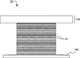
同図(c)は、図示しない外型(金型)に内部コイル50を封入して溶融樹脂を射出し、内部コイル50を外装樹脂部材65で封止してなるコイル部品100の縦断面模式図である。外装樹脂部材65は、図示のようにフランジ部14a,14bおよびコイルワイヤ40を掩覆し、内部コイル50を電気的、熱的、および機械的に保護している。外装樹脂部材65は、巻回されたコイルワイヤ40の外部を掩覆し、その内部には挿し込まない。特にフランジ部14b側については、これに最も近接するコイルワイヤ40aによって外装樹脂部材65の挿込みが防止されている。またコイルワイヤ40が千鳥状に整列巻回されていることにより、重なり合う層同士は緊密に接触し、コイルワイヤ40同士の隙間から外装樹脂部材65が挿し込むことも防止されている。
FIG. 4C is a schematic longitudinal sectional view of a
一方、フランジ部14a側については、コイルワイヤ導入溝20およびコイルワイヤ案内部22を通じて溶融樹脂がフランジ部14aと巻回コイル45との間に僅かに流入するものの、コイルワイヤ案内部22の下方に伸びて形成された巻線ガイド243によってコイルワイヤ40は図中下方への移動が規制されていることにより、巻回コイル45の上端面はほとんど押し下げられることがない。したがって溶融樹脂が巻回コイル45の上端面に与える押圧荷重は、巻回コイル45から巻線ガイド243に伝えられるため、引込線41に過大な引張荷重が負荷されることがなく、流れ込み(i)の問題は発生しない。また、上述のように本発明のコイルボビン10では、溶融樹脂がコイルワイヤ40と構成面16との間から深く浸入する挿込み(ii)の問題についても、巻線ガイド24の存在によって防止している。
これにより、内部コイル50の全体として、射出された溶融樹脂の流れ込みおよび挿込みの問題が解消される。
On the other hand, on the
Thereby, the problem of the flow and insertion of the injected molten resin is solved as the whole
図7(a)は、巻芯部12の巻軸中心と境界位置221とを通る平面で内部コイル50を切った部分縦断面模式図であり、コイルワイヤ導入溝20およびコイルワイヤ案内部22を通じて流れ込んだ溶融樹脂60が、巻回された最下層のコイルワイヤ40と構成面16との間を通じて本実施形態の内部コイル50に挿し込む様子を示している。ただし同図では、二層目以降に巻回されたコイルワイヤ40は図示を省略している。
同図(a)に示す巻芯部12には、図1,2にも図示のように、構成面16より突出する凸条によって巻線ガイド24(243,244,・・・)が構成されている。
一方、同図(b)に示す内部コイル50ではその変形例として、構成面16に掘り込み形成された凹溝によって巻線ガイド24(241,242,243,・・・)が構成されている。
FIG. 7A is a partial vertical cross-sectional schematic view in which the
As shown in FIGS. 1 and 2, a winding guide 24 (243, 244,...) Is formed on the winding
On the other hand, in the
両ケースとも、1ターン目のコイルワイヤ40は、コイルワイヤ案内部22にガイドされて、構成面16と面一にある境界位置221より巻芯部12に導入される。したがって1ターン目のコイルワイヤ40は、構成面16上に巻回されている。
In both cases, the
同図(a)に示す本実施形態の内部コイル50の場合、図2に示すように巻線ガイド241および巻線ガイド242の始端241a,242aが境界位置221よりも巻回方向WDの前方に設けられ、コイルワイヤ案内部22の近傍にはガイド非形成部26が形成されていることから、コイルワイヤ導入溝20およびコイルワイヤ案内部22を介して巻芯部12側に流れ込んだ溶融樹脂60は、1ターン目のコイルワイヤ40と構成面16との隙間を伝って内部コイル50の内部に浸入し、2ターン目のコイルワイヤ40を超える深さまで挿し込む。
しかし、コイルワイヤ案内部22を軸線161方向に挿し込んだ溶融樹脂60は、構成面16より突出形成された巻線ガイド243に堰き止められて、3ターン目のコイルワイヤ40に至ることはできない。
これにより、内部コイル50への溶融樹脂60(外装樹脂部材65)の挿込みは僅かにコイルワイヤ40の2ターン分の深さで抑制される。
In the case of the
However, the
Thereby, insertion of the molten resin 60 (exterior resin member 65) into the
したがってかかる内部コイル50を外装樹脂部材65で封止したコイル部品100を熱サイクル下で長期使用した場合も、内部コイル50内部で熱膨張/熱収縮する外装樹脂部材65の量が僅かであることから、コイルワイヤ40に負荷される引張応力も僅かであり、コイルワイヤ導入溝20およびコイルワイヤ案内部22を介して巻芯部12側に引き込まれるコイルワイヤ40が破断することがない。
Therefore, even when the
一方、同図(b)に示す内部コイル50の場合、構成面16上に巻回される1ターン目のコイルワイヤ40を超えて溶融樹脂60の挿込みは内部コイル50の内部に進行するが、2ターン目のコイルワイヤ40をガイドする巻線ガイド241が凹溝によって形成されているため、巻線ガイド241と巻線ガイド242との間の凸部(当該凸部の上面が構成面16にあたる)にて、かかる挿込みは堰き止められる。したがって上記変形例にかかる内部コイル50の場合についても、コイルワイヤ40の2ターン分の深さにて溶融樹脂60の挿込みを抑えることができる。
On the other hand, in the case of the
また、巻回コイル45の上端面が図中下方へ押し下げられる変形量としては、同図(a),(b)の場合とも、わずかに1ターン目と2ターン目のクリアランス、および2ターン目と巻線ガイド243とのクリアランスの合計長に限られるため、仮に溶融樹脂による巻回コイル45の押圧変形(流れ込み(i))がわずかに生じたとしても、引込線41(図6(c)を参照)には実質的に引張応力が負荷されない。
In addition, the deformation amount by which the upper end surface of the winding
本実施形態のコイルボビン10においては、図1〜3に示すように、フランジ部14aから数えて2ターン目以降のコイルワイヤ40をガイドする巻線ガイド24がいずれも軸線161を跨いで境界位置221の両側に伸びて形成されている。これにより、仮に2ターン目のコイルワイヤ40が巻線ガイド243を乗り越えて下方へ押圧変形しようとした場合も、3ターン目以降のコイルワイヤ40が下方に移動することを規制している。また、巻線ガイド243によっては完全には堰き止められなかった溶融樹脂60が存在したとしても、軸線161方向にこれが進行することを防止している。
ただし本実施形態に代えて、2ターン目のコイルワイヤ40をガイドする巻線ガイド24についてのみ境界位置221を跨いで形成し、3ターン目以降のコイルワイヤ40をガイドする巻線ガイド24については境界位置221の一方側にのみ形成することとしてもよい。
In the
However, instead of this embodiment, only the winding
また本発明においては、後述する第二実施形態のコイルボビン10のように、フランジ部14aに最も近接する1ターン目のコイルワイヤ40をガイドする巻線ガイド24(巻線ガイド241)についても軸線161を跨ぐように形成することもできる。
In the present invention, the
ここで、軸線161を跨いで形成する巻線ガイド24を、境界位置221の両側に対しどの程度の周方向長さに亘って形成するかという点に関しては、特に限定されるものではない。流れ込み(i)の抑制という観点からは、コイルワイヤ案内部22に流入して樹脂溜りを形成した溶融樹脂が巻回コイル45の上端面を押圧することから、軸線161を跨いで、かつコイルワイヤ案内部22(ワイヤ逃げ部223)の下方をカバーする長さ領域に巻線ガイド24を設けるとよい。
一方、挿込み(ii)の抑制という観点からは以下の指標が導かれる。まず、コイルワイヤ導入溝20と構成面16とを結ぶガイド面222のうち、構成面16よりも高い位置から巻芯部12側に流れ込む溶融樹脂に関しては、上述のように内部コイルの層間より浸入する虞は低く、挿込みの問題は生じにくい。
したがって境界位置221よりも巻回方向WDの逆方向に伸びて形成すべき巻線ガイド24の長さとしては、構成面16を基準とするガイド面222の高さH(図2を参照)がコイルワイヤ40の直径1本分以下である領域をカバーするものであることが好ましい。換言すると、コイルワイヤ導入溝20およびコイルワイヤ案内部22の直下のうち、ガイド面222から巻芯部12側に流れ込む溶融樹脂が、内部コイルの下から二層目またはそれよりも外側のコイルワイヤ40のみと接触する幅領域L(図2を参照)については、軸線161方向の下方側に巻線ガイド24による防御壁を立設する必要はなく、最下層のコイルワイヤ40がコイルワイヤ導入溝20またはコイルワイヤ案内部22に露出している領域については、その軸線161方向の下方側に巻線ガイド24による防御壁を立設して溶融樹脂の挿込みを堰き止めるとよい。
Here, the length of the circumferential direction length of the winding
On the other hand, the following indices are derived from the viewpoint of suppressing insertion (ii). First, of the
Therefore, as the length of the winding
本実施形態の巻線ガイド24の場合、始端と終端の間はそれぞれひと続きに形成され、すなわち非環状の巻線ガイド24はそれぞれ一条で構成されている(図4を参照)。
本発明においてはこれに限らず、各巻線ガイド24をそれぞれ分割構成してもよい。ただし、上述のように射出された溶融樹脂が最下層のコイルワイヤ40と接触する虞のある領域においては巻線ガイド24を連続構成とし、仮に内部コイルに溶融樹脂が挿し込んだとしても当該巻線ガイド24によってその進行を防止するとよい。
In the case of the winding
However, the present invention is not limited to this, and each winding
図1,5に示すように、フランジ部14aには、構成面16に巻回されたコイルワイヤ40の終端をフランジ部14aより引き出すためのコイルワイヤ導出部21が形成されている。コイルワイヤ40の終端はフランジ部14aの表面側(先端側)に設けられた外部端子取付基部28bに直接に、または外部端子取付基部28bに装着される金属端子を介して間接に接続される。これにより、外部端子取付基部28aおよび28bがコイルワイヤ40によって電気的に接続される。
コイルワイヤ導出部21は、図示のようにフランジ部14aの外側より巻芯部12の径方向に切り込み形成された溝であっても、コイル巻線装置(図示せず)より切断されたコイルワイヤ40の終端をくぐらせて挿通可能な貫通孔であってもよい。ただしコイルワイヤ40に対してコイル巻線装置によって所定のテンションを負荷したままフランジ部14aを跨いでその終端を外部端子取付基部28bまで案内する場合には、コイル巻線装置とフランジ部14aとが干渉しないよう、コイルワイヤ導出部21を図示のように溝状にするとよい。
As shown in FIGS. 1 and 5, the
The coil wire lead-out
本実施形態の場合、コイルワイヤ導出部21の形成位置はコイルワイヤ40の最大巻径よりもコイルボビン10の径方向の外側である。すなわち構成面16からコイルワイヤ導出部21の最深部211までの径方向の距離は、巻回コイル45の巻厚と同等またはそれ以上である。
これにより、内部コイル50に溶融樹脂60を射出してコイル部品100を封止成型するにあたり、コイルワイヤ導出部21を通じて巻芯部12側に溶融樹脂が流れ込んだとしても、これが巻回コイル45の上端面を押下変形させたり、溶融樹脂が巻回コイル45の内部に挿し込んだりすることがない。コイルワイヤ導出部21においては、巻回コイル45の上端面、特にその最下層が露出していないためである。
In the case of this embodiment, the formation position of the coil wire lead-out
Thus, when the
図8は、本発明の第二の実施形態にかかるコイルボビン10の部分斜視図である。図2に示す第一実施形態とは、フランジ部14aの近傍に設けられた巻線ガイド24の始端および終端の位置が異なる点でのみ相違する。
第二実施形態の場合、1ターン目のコイルワイヤ40をガイドする巻線ガイド241を含めすべての巻線ガイド24が、境界位置221を通る軸線161を跨いで形成されている。
すなわちすべての巻線ガイド24において、終端(241b,242b,243b,・・・)と始端(241a,242a,243a,・・・)との間に形成されるガイド非形成部26が、境界位置221よりも巻回方向の後方側に設けられている。
FIG. 8 is a partial perspective view of the
In the case of the second embodiment, all the winding
That is, in all the winding guides 24, the
これにより、フランジ部14aから数えて1ターン目のコイルワイヤ40をガイドする巻線ガイド241が、1ターン目のコイルワイヤ40の移動を規制するストッパーとして、かつコイルワイヤ案内部22より構成面16に流れ込んで内部コイル50に挿し込む溶融樹脂60を堰き止める防御壁として機能する。
したがって本実施形態の場合、コイルワイヤ導入溝20を通じてワイヤ逃げ部223に流入した溶融樹脂60(外装樹脂部材65)の樹脂溜りが巻回コイル45の上端面を射出圧にて押圧したとしても、1ターン目以降すべてのコイルワイヤ40に対して巻軸方向への移動が規制されるため、ガイド面222を案内される引込線41(図6(c)を参照)に負荷される引張荷重が極めて抑えられる。
また、内部コイル50に挿し込む溶融樹脂60についても、高々1ターン目のコイルワイヤ40の深さに抑えられるため、コイル部品100を熱サイクル下で使用した場合の外装樹脂部材65の熱膨張/熱収縮が第一実施形態の場合よりも低減され、コイルワイヤ40への熱負荷を更に抑えることができる。
As a result, the winding
Therefore, in the case of this embodiment, even if the resin pool of the molten resin 60 (exterior resin member 65) that has flowed into the
Also, the
なお、第二実施形態において巻線ガイド24(241,242,243,・・・)を凹溝によって構成した場合、1ターン目のコイルワイヤ40はわずかながらも下方に移動可能であり、また溶融樹脂60が巻線ガイド241と巻線ガイド242との間まで挿し込む虞がある。1ターン目のコイルワイヤ40は構成面16上に巻回され、2ターン目のコイルワイヤ40は巻線ガイド241に嵌合して巻回されるところ、溶融樹脂60は巻線ガイド241から巻線ガイド242に至る凸部(構成面16)にて堰き止められるためである(図7(b)を参照)。
かかる意味で、本発明においては、巻線ガイド24が巻芯部12の構成面16に対して凸状に形成されていることが好ましいといえる。
In the second embodiment, when the winding guide 24 (241, 242, 243,...) Is constituted by a concave groove, the
In this sense, in the present invention, it can be said that the winding
10 コイルボビン
12 巻芯部
14a,14b フランジ部
16 構成面
161 軸線
20 コイルワイヤ導入溝
21 コイルワイヤ導出部
22 コイルワイヤ案内部
221 境界位置
222 ガイド面
223 ワイヤ逃げ部
24 巻線ガイド
26 ガイド非形成部
28a,28b 外部端子取付基部
40 コイルワイヤ
50 内部コイル
60 溶融樹脂
65 外装樹脂部材
100 コイル部品
WD 巻回方向
DESCRIPTION OF
Claims (4)
前記フランジ部には、
前記フランジ部の外周側から所定の深さで切り込み形成され、巻軸方向の前記一端側から巻芯部にむけてコイルワイヤを引き込むためのコイルワイヤ導入溝と、
前記コイルワイヤ導入溝と連通し、該コイルワイヤ導入溝より前記巻芯部の構成面に向かって引き込まれたコイルワイヤを案内するためのコイルワイヤ案内部とが形成され、
前記コイルワイヤ案内部は、
前記コイルワイヤ導入溝と前記構成面とを結び、前記コイルワイヤを案内するガイド面と、
前記コイルワイヤ導入溝と連通して形成され、案内されるコイルワイヤと前記フランジ部とが干渉しないようにするワイヤ逃げ部とを備え、
前記巻芯部の構成面には、
コイルワイヤの巻回方向に伸びて前記案内されたコイルワイヤを整列巻回するための非環状の巻線ガイドと、
巻回されるコイルワイヤの巻回ターンを切り換えるためのガイド非形成部とが設けられるとともに、
前記巻線ガイドは、前記フランジ部に最も近接するターンのコイルワイヤをガイドするための巻線ガイドが、前記コイルワイヤ案内部と前記巻芯部の構成面との境界位置を通る軸線よりも巻回方向に位置するように設けられ、前記フランジ部より数えて2ターン目以降のコイルワイヤをガイドするための巻線ガイドが、前記軸線を跨いで形成されていることを特徴とするコイルボビン。 A winding core portion and a flange portion provided at at least one end in the winding axis direction of the winding core portion, and the coil wire is formed in a desired number of turns along the winding axis direction with respect to the constituent surface of the winding core portion. A coil bobbin wound around
In the flange portion,
A coil wire introduction groove formed by cutting at a predetermined depth from the outer peripheral side of the flange portion, and for drawing the coil wire from the one end side in the winding axis direction toward the core portion ;
A coil wire guide portion is formed which communicates with the coil wire introduction groove and guides the coil wire drawn from the coil wire introduction groove toward the constituent surface of the core portion.
The coil wire guide is
A guide surface that guides the coil wire by connecting the coil wire introduction groove and the component surface;
A wire escape portion that is formed in communication with the coil wire introduction groove and prevents the guided coil wire from interfering with the flange portion;
In the configuration surface of the core part,
A non-circular winding guide for aligning and winding the guided coil wire extending in the winding direction of the coil wire;
A non-guide forming portion for switching the winding turn of the coil wire to be wound is provided,
In the winding guide, the winding guide for guiding the coil wire of the turn closest to the flange portion is wound more than the axis passing through the boundary position between the coil wire guide portion and the constituent surface of the core portion . A coil bobbin, characterized in that a winding guide is provided so as to be positioned in the turning direction and guides the coil wire of the second turn and thereafter counting from the flange portion, straddling the axis .
Priority Applications (1)
| Application Number | Priority Date | Filing Date | Title |
|---|---|---|---|
| JP2007222553A JP4981587B2 (en) | 2007-08-29 | 2007-08-29 | Coil bobbin |
Applications Claiming Priority (1)
| Application Number | Priority Date | Filing Date | Title |
|---|---|---|---|
| JP2007222553A JP4981587B2 (en) | 2007-08-29 | 2007-08-29 | Coil bobbin |
Publications (2)
| Publication Number | Publication Date |
|---|---|
| JP2009054937A JP2009054937A (en) | 2009-03-12 |
| JP4981587B2 true JP4981587B2 (en) | 2012-07-25 |
Family
ID=40505724
Family Applications (1)
| Application Number | Title | Priority Date | Filing Date |
|---|---|---|---|
| JP2007222553A Active JP4981587B2 (en) | 2007-08-29 | 2007-08-29 | Coil bobbin |
Country Status (1)
| Country | Link |
|---|---|
| JP (1) | JP4981587B2 (en) |
Families Citing this family (11)
| Publication number | Priority date | Publication date | Assignee | Title |
|---|---|---|---|---|
| WO2011021288A1 (en) * | 2009-08-19 | 2011-02-24 | 三菱電機株式会社 | Vibration damping device for elevator |
| JP5381673B2 (en) * | 2009-12-14 | 2014-01-08 | 住友電気工業株式会社 | Reactor |
| JP6031768B2 (en) * | 2012-01-27 | 2016-11-24 | スミダコーポレーション株式会社 | Bobbin |
| JP5890334B2 (en) | 2013-02-04 | 2016-03-22 | トヨタ自動車株式会社 | Reactor |
| KR200477516Y1 (en) | 2013-12-19 | 2015-06-17 | 엘에스산전 주식회사 | Bobin |
| JP6130349B2 (en) * | 2014-12-25 | 2017-05-17 | トヨタ自動車株式会社 | Reactor manufacturing method |
| JP6668726B2 (en) * | 2015-12-10 | 2020-03-18 | 株式会社デンソー | solenoid valve |
| JP6416315B1 (en) * | 2017-04-26 | 2018-10-31 | 三菱電機株式会社 | Bobbin and coil device using the same |
| DE102017211400B4 (en) * | 2017-07-04 | 2019-01-31 | Richard Wolf Gmbh | Sound wave treatment device |
| JP2019175972A (en) * | 2018-03-28 | 2019-10-10 | 日本電産トーソク株式会社 | Solenoid of electromagnetic valve |
| JP7168902B2 (en) * | 2018-07-30 | 2022-11-10 | Tdk株式会社 | Bobbin and coil device |
Family Cites Families (5)
| Publication number | Priority date | Publication date | Assignee | Title |
|---|---|---|---|---|
| JPH0291312U (en) * | 1988-12-28 | 1990-07-19 | ||
| JPH063764B2 (en) * | 1989-01-13 | 1994-01-12 | 日本電装株式会社 | Coil device |
| JPH02209703A (en) * | 1989-02-09 | 1990-08-21 | Matsushita Electric Ind Co Ltd | Coil bobbin |
| JP3029568B2 (en) * | 1996-03-14 | 2000-04-04 | 株式会社ホンダロック | Coil bobbin |
| JP2001052916A (en) * | 1999-08-13 | 2001-02-23 | Sanden Corp | Bobbin and coil device |
-
2007
- 2007-08-29 JP JP2007222553A patent/JP4981587B2/en active Active
Also Published As
| Publication number | Publication date |
|---|---|
| JP2009054937A (en) | 2009-03-12 |
Similar Documents
| Publication | Publication Date | Title |
|---|---|---|
| JP4981587B2 (en) | Coil bobbin | |
| US7187262B1 (en) | Plastic sealing of solenoid bobbins | |
| CN107061839A (en) | The solenoid of magnetic valve | |
| CN110808645B (en) | Cooling structure applied to oil-cooled flat wire motor stator | |
| US9759172B2 (en) | Fuel injector having a reduced number of components | |
| JP2011143711A (en) | Insert molding method and insert molded product | |
| JP5620243B2 (en) | Coil stator | |
| JP6229305B2 (en) | ANTENNA DEVICE AND ANTENNA DEVICE MANUFACTURING METHOD | |
| KR20130102110A (en) | Pitched cable having a flexible core around which a coil is wrapped | |
| EP0834978B1 (en) | Bobbin for electromagnet of electromagnetic clutch | |
| JP2011153697A (en) | Method for manufacturing solenoid valve coil and solenoid valve | |
| JPWO2017158784A1 (en) | Insulator for stator and coil terminal wire introduction method | |
| JP4900294B2 (en) | Split stator manufacturing method | |
| US20170167626A1 (en) | Electromagnetic valve | |
| CN109155562B (en) | Terminal block for motor, blower, and method for connecting terminal pin and connection terminal | |
| JP5246755B2 (en) | Trans bobbin | |
| KR100695323B1 (en) | Armature core and manufacturing method thereof | |
| JP6239323B2 (en) | Stator unit | |
| KR102546890B1 (en) | Stator assembly for winding motor | |
| WO2013157089A1 (en) | Solenoid-operated fuel injection valve | |
| JP6413004B2 (en) | Stator unit | |
| KR200203633Y1 (en) | Bobbin for a transformer | |
| JP4437395B2 (en) | Motor stator | |
| JP6144867B2 (en) | Molded coil | |
| KR200203632Y1 (en) | Bobbin for a transformer |
Legal Events
| Date | Code | Title | Description |
|---|---|---|---|
| A621 | Written request for application examination |
Free format text: JAPANESE INTERMEDIATE CODE: A621 Effective date: 20100517 |
|
| A977 | Report on retrieval |
Free format text: JAPANESE INTERMEDIATE CODE: A971007 Effective date: 20110720 |
|
| A131 | Notification of reasons for refusal |
Free format text: JAPANESE INTERMEDIATE CODE: A131 Effective date: 20110727 |
|
| A521 | Request for written amendment filed |
Free format text: JAPANESE INTERMEDIATE CODE: A523 Effective date: 20110916 |
|
| TRDD | Decision of grant or rejection written | ||
| A01 | Written decision to grant a patent or to grant a registration (utility model) |
Free format text: JAPANESE INTERMEDIATE CODE: A01 Effective date: 20120404 |
|
| A01 | Written decision to grant a patent or to grant a registration (utility model) |
Free format text: JAPANESE INTERMEDIATE CODE: A01 |
|
| A61 | First payment of annual fees (during grant procedure) |
Free format text: JAPANESE INTERMEDIATE CODE: A61 Effective date: 20120420 |
|
| FPAY | Renewal fee payment (event date is renewal date of database) |
Free format text: PAYMENT UNTIL: 20150427 Year of fee payment: 3 |
|
| R150 | Certificate of patent or registration of utility model |
Ref document number: 4981587 Country of ref document: JP Free format text: JAPANESE INTERMEDIATE CODE: R150 Free format text: JAPANESE INTERMEDIATE CODE: R150 |
|
| S531 | Written request for registration of change of domicile |
Free format text: JAPANESE INTERMEDIATE CODE: R313531 |
|
| R350 | Written notification of registration of transfer |
Free format text: JAPANESE INTERMEDIATE CODE: R350 |
|
| R250 | Receipt of annual fees |
Free format text: JAPANESE INTERMEDIATE CODE: R250 |
|
| R250 | Receipt of annual fees |
Free format text: JAPANESE INTERMEDIATE CODE: R250 |
|
| R250 | Receipt of annual fees |
Free format text: JAPANESE INTERMEDIATE CODE: R250 |
|
| R250 | Receipt of annual fees |
Free format text: JAPANESE INTERMEDIATE CODE: R250 |
|
| R250 | Receipt of annual fees |
Free format text: JAPANESE INTERMEDIATE CODE: R250 |
|
| R250 | Receipt of annual fees |
Free format text: JAPANESE INTERMEDIATE CODE: R250 |
|
| S531 | Written request for registration of change of domicile |
Free format text: JAPANESE INTERMEDIATE CODE: R313531 |
|
| R350 | Written notification of registration of transfer |
Free format text: JAPANESE INTERMEDIATE CODE: R350 |
|
| R250 | Receipt of annual fees |
Free format text: JAPANESE INTERMEDIATE CODE: R250 |
|
| R250 | Receipt of annual fees |
Free format text: JAPANESE INTERMEDIATE CODE: R250 |