JP4979839B2 - Drive transmission device and image forming apparatus - Google Patents
Drive transmission device and image forming apparatus Download PDFInfo
- Publication number
- JP4979839B2 JP4979839B2 JP2012004255A JP2012004255A JP4979839B2 JP 4979839 B2 JP4979839 B2 JP 4979839B2 JP 2012004255 A JP2012004255 A JP 2012004255A JP 2012004255 A JP2012004255 A JP 2012004255A JP 4979839 B2 JP4979839 B2 JP 4979839B2
- Authority
- JP
- Japan
- Prior art keywords
- coupling
- unit
- main body
- contact
- apparatus main
- Prior art date
- Legal status (The legal status is an assumption and is not a legal conclusion. Google has not performed a legal analysis and makes no representation as to the accuracy of the status listed.)
- Active
Links
Images


Classifications
-
- G—PHYSICS
- G03—PHOTOGRAPHY; CINEMATOGRAPHY; ANALOGOUS TECHNIQUES USING WAVES OTHER THAN OPTICAL WAVES; ELECTROGRAPHY; HOLOGRAPHY
- G03G—ELECTROGRAPHY; ELECTROPHOTOGRAPHY; MAGNETOGRAPHY
- G03G21/00—Arrangements not provided for by groups G03G13/00 - G03G19/00, e.g. cleaning, elimination of residual charge
- G03G21/16—Mechanical means for facilitating the maintenance of the apparatus, e.g. modular arrangements
- G03G21/1642—Mechanical means for facilitating the maintenance of the apparatus, e.g. modular arrangements for connecting the different parts of the apparatus
- G03G21/1647—Mechanical connection means
-
- G—PHYSICS
- G03—PHOTOGRAPHY; CINEMATOGRAPHY; ANALOGOUS TECHNIQUES USING WAVES OTHER THAN OPTICAL WAVES; ELECTROGRAPHY; HOLOGRAPHY
- G03G—ELECTROGRAPHY; ELECTROPHOTOGRAPHY; MAGNETOGRAPHY
- G03G21/00—Arrangements not provided for by groups G03G13/00 - G03G19/00, e.g. cleaning, elimination of residual charge
- G03G21/16—Mechanical means for facilitating the maintenance of the apparatus, e.g. modular arrangements
- G03G21/18—Mechanical means for facilitating the maintenance of the apparatus, e.g. modular arrangements using a processing cartridge, whereby the process cartridge comprises at least two image processing means in a single unit
- G03G21/1839—Means for handling the process cartridge in the apparatus body
- G03G21/1857—Means for handling the process cartridge in the apparatus body for transmitting mechanical drive power to the process cartridge, drive mechanisms, gears, couplings, braking mechanisms
- G03G21/186—Axial couplings
Abstract
Description
本発明は、画像形成装置本体に対して着脱可能なユニットに関する。 The present invention relates to a unit that can be attached to and detached from an image forming apparatus main body.
近年、電子写真方式のプリンタや複写機などの画像形成装置においては、小型化や操作性の向上が望まれている。 In recent years, in an image forming apparatus such as an electrophotographic printer or a copying machine, downsizing and improvement in operability are desired.
画像形成装置の操作性向上と言う観点から、感光体、帯電手段、現像手段、クリーニング手段などを一体にまとめてカートリッジ化し、このカートリッジを画像形成装置本体に着脱可能とするプロセスカートリッジ方式が採用されている。このカートリッジ方式により操作性が一層向上し、現像などの上記プロセス手段のメンテナンスをユーザ自身が容易に行なうことが可能となった。 From the viewpoint of improving the operability of the image forming apparatus, a process cartridge system is adopted in which the photosensitive member, the charging unit, the developing unit, the cleaning unit, etc. are integrated into a cartridge and the cartridge can be attached to and detached from the main body of the image forming apparatus. ing. The operability is further improved by this cartridge system, and the user can easily perform maintenance of the process means such as development.
これと同様に、画像形成装置本体の中間転写体などもユニット構成となり、画像形成装置本体に対して着脱可能とし、操作性、及びメンテナンス性の向上を図っている。 Similarly, the intermediate transfer member of the image forming apparatus main body has a unit configuration and is detachable from the image forming apparatus main body, thereby improving operability and maintenance.
また、画像形成装置本体に対して着脱可能なこれらのユニットへ、駆動を安定して確実に伝達する駆動伝達装置として、図26に示すような凸部と、それに対応する凹部との組み合わせで行なうカップリングが用いられている。 Further, as a drive transmission device that stably and reliably transmits drive to these units that can be attached to and detached from the image forming apparatus main body, a combination of a convex portion as shown in FIG. 26 and a concave portion corresponding thereto is performed. Coupling is used.
特許文献1には、カップリング対が開閉するカバーなどに連動し、カバーを開ける操作により、装置本体側のカップリングがユニット側のカップリングから退避することから、カップリング対の連結が外れ、ユニットの着脱を可能とする構成が開示されている。
In
しかしながら、カバーの開閉操作と連動し、カップリングを解除、連結するためには、カバーの開閉機構部に加えて、カップリングを解除、連結させるための機構を設ける必要がある。この機構によってカバーの開閉操作性の悪化や、構成が複雑になることによるコストアップを招いていた。 However, in order to release and connect the coupling in conjunction with the opening and closing operation of the cover, it is necessary to provide a mechanism for releasing and connecting the coupling in addition to the opening and closing mechanism portion of the cover. With this mechanism, the opening / closing operability of the cover is deteriorated, and the cost is increased due to the complicated configuration.
例えば、カップリングを連結、解除するために、リンク機構が開閉カバーに設けてある場合には、カバーを開閉するたびにカップリングの解除、連結が行なわれ、本来必要でないカップリングの解除、連結の負荷をカバーが担うこととなる。ともすると、カップリングを解除、連結するために要する抵抗などの負荷が、カバーを開閉するための操作力に加わってしまう。特に、プロセスカートリッジが4つ並んでいるカラー画像形成装置においては、カップリングを解除、連結するための負荷も大きなものとなり、そのため、カバーを開閉する操作性が悪くなっていた。 For example, when a link mechanism is provided on the opening / closing cover to connect and release the coupling, the coupling is released and connected every time the cover is opened and closed, and the coupling is released and connected which is not necessary. The cover will bear the load. In this case, a load such as a resistance required for releasing and coupling the coupling is applied to an operation force for opening and closing the cover. In particular, in a color image forming apparatus in which four process cartridges are arranged, the load for releasing and coupling the coupling becomes large, and the operability for opening and closing the cover is deteriorated.
また、リンク機構は剛性の高いものが要求される。さらに、リンク機構そのものが大きなものになることやカバーの剛性アップが必要となることから、装置の大型化やコストアップに繋がっていた。 The link mechanism is required to have high rigidity. Furthermore, since the link mechanism itself becomes large and the rigidity of the cover needs to be increased, the apparatus is increased in size and cost.
上記課題を解決するための本発明のユニットは、
駆動力を伝達する回転可能な本体カップリングを有する電子写真画像形成装置本体に着脱可能なユニットであって、
前記本体カップリングから前記駆動力を受ける回転可能なユニットカップリングを有し、
前記ユニットは、前記装置本体から取り外される際に、前記装置本体に対して前記ユニットカップリングの回転軸線と略垂直な第一方向に移動可能であり、
前記ユニットカップリングは、前記ユニットの本体に対して前記ユニットカップリングの回転軸線と略平行な第二方向に移動可能であり、
前記本体カップリング又は前記ユニットカップリングの一方は、傾斜部を有しており、
前記本体カップリング又は前記ユニットカップリングの他方は、前記傾斜部に当接可能な当接部を有しており、
前記装置本体から前記ユニットが取り外される際に、前記傾斜部と前記当接部とが当接した状態で前記ユニットが前記第一方向に移動することにより、前記ユニットカップリングが、前記本体カップリングから力を受けて前記ユニットの本体に対して前記第二方向に移動し、前記本体カップリングから退避することを特徴とする。
The unit of the present invention for solving the above problems is
A unit detachably attached to an electrophotographic image forming apparatus main body having a rotatable main body coupling for transmitting a driving force,
A rotatable unit coupling that receives the driving force from the body coupling;
The unit is movable in a first direction substantially perpendicular to a rotation axis of the unit coupling with respect to the apparatus main body when removed from the apparatus main body,
The unit coupling is movable in a second direction substantially parallel to the rotation axis of the unit coupling with respect to the main body of the unit;
One of the main body coupling or the unit coupling has an inclined portion,
The other of the main body coupling or the unit coupling has a contact portion that can contact the inclined portion,
When the unit is removed from the apparatus main body, the unit coupling is moved to the first direction in a state where the inclined portion and the abutting portion are in contact with each other. Receiving the force from the unit, the unit moves in the second direction with respect to the main body of the unit, and retracts from the main body coupling.
本発明によれば、ユニットと装置本体間のカップリングが、ユニットの装置本体からの離脱行為に伴って解除される。 According to the present invention, the coupling between the unit and the apparatus main body is released when the unit is detached from the apparatus main body.
(実施の形態1)
本実施の形態は、装置本体に電子写真方式で4連ドラム方式のカラー画像形成装置を用い、着脱可能なユニットとして中間転写ユニットを用いて説明する。また、本実施の形態では、中間転写ユニット内の一次転写ローラを、対応する感光ドラムから離間させる駆動力を装置本体から伝達するため、駆動伝達装置を用いている。本実施の形態の駆動伝達装置は、第1のカップリングと、第1のカップリングと噛み合って回転する第2のカップリングを有する。
(Embodiment 1)
In this embodiment, an electrophotographic four-drum color image forming apparatus is used as the apparatus body, and an intermediate transfer unit is used as a detachable unit. In this embodiment, a drive transmission device is used to transmit a driving force for separating the primary transfer roller in the intermediate transfer unit from the corresponding photosensitive drum from the apparatus main body. The drive transmission device of the present embodiment has a first coupling and a second coupling that rotates in mesh with the first coupling.
以下、本発明の一実施の形態を、図1〜図12に従って、画像形成装置、中間転写ユニット、駆動伝達装置の順に説明する。 Hereinafter, an embodiment of the present invention will be described in the order of an image forming apparatus, an intermediate transfer unit, and a drive transmission apparatus according to FIGS.
[画像形成装置]
まず、装置本体100の構成について説明する。
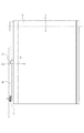
図1は、本発明に従う画像形成装置の一例を示す断面図である。
[Image forming apparatus]
First, the configuration of the apparatus
FIG. 1 is a sectional view showing an example of an image forming apparatus according to the present invention.
(1)トナー像の形成プロセス
トナー像の形成は、感光体である感光ドラム1、帯電ユニットである帯電ローラ2、露光ユニット3、現像ユニット4などにより行なわれる。装置本体100は4個の感光ドラム1a、1b、1c、1dを備えている。それぞれの感光ドラム1の周囲には、その回転方向に従って、順に、感光ドラム1表面を均一に帯電する帯電ローラ2(2a、2b、2c、2d)、画像情報に基いてレーザを照射し感光ドラム1上に静電潜像を形成する露光ユニット3がある。また、感光ドラム1上の静電潜像にトナーを付着させトナー像として顕像化する現像ユニット4(4a、4b、4c、4d)、感光ドラム1上のトナー像を中間転写ベルト12eに転写する転写手段12a、12b、12c、12dがある。更に、転写後の感光ドラム1表面に残った転写後トナーを除去するクリーニング手段8(8a、8b、8c、8d)などが配設してある。
(1) Toner Image Forming Process The toner image is formed by the
感光ドラム1、帯電ローラ2、現像ユニット4、及びクリーニング手段8(8a、8b、8c、8d)は、各々一体的にカートリッジ化して、プロセスカートリッジ7(7a、7b、7c、7d)としている。プロセスカートリッジは、各々装置本体100に着脱可能に構成されている。これら4個のプロセスカートリッジ7a、7b、7c、7dは同一構造であるが、イエロー(Y)、マゼンダ(M)、シアン(C)、ブラック(Bk)のトナーを用いて異なる色の画像を形成する点で相違している。
The
プロセスカートリッジ7a、7b、7c、7dは、現像ユニット4a、4b、4c、4dとクリーニングユニット5a、5b、5c、5dによって構成されている。このうち前者の現像ユニット4a、4b、4c、4dは、現像ローラ24a、24b、24c、24d、現像剤塗布ローラ25a、25b、25c、25d、及びトナー容器を有している。後者のクリーニングユニット5a、5b、5c、5dは、感光ドラム1a、1b、1c、1d、帯電ローラ2a、2b、2c、2d、クリーニング手段8a、8b、8c、8d、及び転写残トナー容器を有している。
The process cartridges 7a, 7b, 7c, 7d are constituted by developing
感光ドラム1a、1b、1c、1dは、アルミニウム製シリンダの外周面に、有機光導伝体層(OPC)を塗布して構成したものであり、その両端部をフランジによって回転自在に支持されている。感光ドラム1a、1b、1c、1dの一方の端部に駆動モータ(不図示)から駆動力を伝達することにより、図1の矢印に示す方向時計回り方向に回転駆動する。
Each of the
帯電ローラ2a、2b、2c、2dは、ローラ状に形成された導電性ローラである。このローラを感光ドラム1a、1b、1c、1d表面に当接させると共に、電源回路(不図示)によって帯電電圧を印加して感光ドラム1a、1b、1c、1d表面を一様に帯電させる。露光ユニット3は、プロセスカートリッジ7(7a、7b、7c、7d)の鉛直下方に配置してあり、画像信号に基く露光を感光ドラム1a、1b、1c、1dに対して行なう。
The charging
トナー容器には、それぞれイエロー(Y)、マゼンダ(M)、シアン(C)、ブラック(Bk)の各色のトナーが収納してある。
現像ローラ24a、24b、24c、24dは、感光ドラム1a、1b、1c、1d表面に隣接して配置してあり、駆動部(不図示)により回転駆動されると共に、電圧を印加することにより、感光ドラム1a、1b、1c、1d表面に現像する。
Each toner container contains toner of each color of yellow (Y), magenta (M), cyan (C), and black (Bk).
The developing rollers 24a, 24b, 24c, and 24d are arranged adjacent to the surface of the
以上の構成により、感光ドラム1a、1b、1c、1d表面に、Y、M、C、Bkのトナー像が形成される。感光ドラム1a、1b、1c、1d表面に形成されたトナー像は、順次、中間転写ベルト12e表面へ一次転写される。その後、感光ドラム1a、1b、1c、1d表面に残ったトナーは、クリーニング手段8a、8b、8c、8dによって除去され、クリーニングユニット5a、5b、5c、5d内の転写材トナー容器に回収される。
With the above configuration, toner images of Y, M, C, and Bk are formed on the surfaces of the
(2)転写材への転写及び、定着プロセス
転写材Sへのトナー像の転写は、給紙装置13によって転写材が二次転写部15に搬送されて二次転写部15で行われる。中間転写ユニット12は、一次転写プロセスにより形成されたトナー像を担持し、トナー像を二次転写部15まで搬送する。定着装置14は、二次転写部15の下流側に位置し、転写材に転写されたトナー像を転写材S上に定着する。
(2) Transfer onto Transfer Material and Fixing Process Transfer of the toner image onto the transfer material S is performed by the secondary transfer unit 15 after the transfer material is conveyed to the secondary transfer unit 15 by the
給紙装置13は、主に転写材Sを収納する給紙カセット11、給紙ローラ9、分離手段23、転写材Sを挟持搬送するレジストローラ対10から構成されている。定着装置14は、定着フィルム14a、加圧ローラ14b、加熱体14c、排紙ローラ対20から構成されている。
The
給紙カセット11は装置本体手前方向(図1中では、装置本体の左側)に引き抜くことができる。ユーザは、給紙カセット11を引き抜き、装置本体100から引き出した後、給紙カセット11に転写材Sをセットし、装置本体100へ挿入することで、転写材Sの補給を行なうことができる。給紙ローラ9は、給紙カセット11に収納された転写材Sと圧接しており、所定の制御タイミングで回転することから転写材Sを送り出し、転写材Sが分離手段23により一枚ずつに分離され給紙される。その後、転写材Sは、レジストローラ対10によって二次転写部15へと搬送される。
The
二次転写部15では、二次転写手段16にバイアスが印加され、中間転写ベルト12e上のトナー像が二次転写部15に搬送されてきた転写材S上に転写される。
In the secondary transfer unit 15, a bias is applied to the
定着フィルム14aは、無端円筒状のベルトであり、定着フィルム14aの外周面が、転写材S上のトナー画像面側に配してある。加熱体14cは、定着フィルム14aの内側に配置されており、加圧ローラ14bが、定着フィルム14aを介して圧接している。加圧ローラ14bが、駆動手段(不図示)により回転駆動し、それに伴なって定着フィルム14aが回転し、加熱体14cにより、定着フィルム14aは加熱される。二次転写部15から搬送された転写材Sが、定着フィルム14aと加圧ローラ14bに挟持搬送され、トナー画像は、転写材S上に加熱定着する。トナー画像が定着した転写材Sは、その後、排紙ローラ対20により挟持搬送され、排紙トレイ上に排出される。
The fixing film 14 a is an endless cylindrical belt, and the outer peripheral surface of the fixing film 14 a is arranged on the toner image surface side on the transfer material S. The
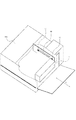
[中間転写ユニット]
本実施の形態では、中間転写ユニット12が、装置本体に対して着脱可能なユニットである。図2に示すように、中間転写ユニット12は、装置本体100に対して矢印に示すA方向へ着脱可能に構成されている。
[Intermediate transfer unit]
In the present embodiment, the
中間転写ユニット12は、主に、中間転写ベルト(中間転写材)12e、駆動ローラ12f、従動ローラ12g、一次転写手段である一次転写ローラ12a、12b、12c、12d、クリーニング手段22、一次転写離間手段30から構成されている。中間転写ベルト12eは、駆動ローラ12f、従動ローラ12gに張架されている。従動ローラ12gは、図1の矢印に示すE方向に付勢手段により付勢されており、中間転写ベルト12eに所定の張力を付与している。
The
駆動ローラ12fが、モータ(不図示)などにより回転駆動することから、中間転写ベルト12eは、図1の矢印に示すF方向に所定の速度で回転する。
Since the drive roller 12f is rotationally driven by a motor (not shown) or the like, the
各一次転写ローラ12a、12b、12c、12dは、各感光ドラム1a、1b、1c、1dに対向して、中間転写ベルト12eの内側に配設されており、付勢部材31によって感光ドラム1側へ付勢されている。一次転写ローラ12a、12b、12c、12dに電圧を印加することによって、各感光ドラム1a、1b、1c、1d表面に形成されたトナー像は、中間転写ベルト12e上に一次転写される。中間転写ベルト上には、4色のトナー像が重ねて転写され、中間転写ベルト12上のトナー像は二次転写部15まで搬送される。
The
二次転写後に、中間転写ベルト12e上に残ったトナーは、クリーニング手段22によって除去され、転写残トナー搬送路(不図示)を経由し、装置本体100内に配設されたトナー回収容器(不図示)に回収される。
After the secondary transfer, the toner remaining on the
中間転写ユニット12には、カラー画像形成時に中間転写ベルト12eを介して感光ドラム1に当接しているY、M、Cに対応する一次転写ローラの離間構成がある。モノ画像形成時に使用しない感光ドラム1との摺擦を抑止し、感光ドラム1の延命を図るためである。
The
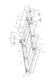
図9、図10は、本実施の形態における一次転写離間手段30の一例を示すものである。
一次転写離間手段30は、主にカム軸32、スライド部材33a、33b、カム部材34a、34bから構成されている。カム軸32の両端には対象形状であるカム部材34a、34bが配設してあり、スライド部材33a、33bは一次転写ローラ12a、12b、12cの両端に配設してある。スライド部材が左右に移動することで、一次転写ローラ12a、12b、12cの各感光ドラム1a、1b、1cに対する位置を変更することが可能である。
9 and 10 show an example of the primary transfer separation means 30 in the present embodiment.
The primary transfer separation means 30 mainly includes a
カラー画像形成時は、カム部材34a、34bが図9に示すように位相Gの状態となり、スライド部材33a、33bは位置Jの状態に保持される。このことにより、各一次転写ローラ12a、12b、12c、12dは中間転写ベルト12eを介して各感光ドラム1a、1b、1c、1dに当接する。
During color image formation, the
図10に示すように、カム軸32が、駆動伝達装置(後述)により動力を受け、カム部材34a、34bが図示C方向に回転することから、スライド部材33a、33bは図示D方向へ移動する。モノ画像形成時は、カム部材34a、34bが図5に示すように位相Hの状態となり、スライド部材33a、33bは位置Kの状態で保持される。そして、Y、M、Cに対応する一次転写ローラ12a、12b、12cは、スライド部材33a、33bにより付勢方向に反して感光ドラム1a、1b、1cから退避した位置へ移動、保持され、感光ドラム1a、1b、1cから離間する。さらにカム部材34a、34bが図示C方向に回転すると、位相Gの状態へと戻り、スライド部材33a、33bも位置Jの状態となる。
As shown in FIG. 10, the
[駆動伝達装置]
本実施の形態における駆動伝達装置40は、以下に説明する第1のカップリングである駆動カップリング41と、第2のカップリングである被駆動カップリングを有する。第1のカップリングは、装置本体に設けられており、駆動源による動力で回転するカップリングである。第2のカップリングは、ユニットに設けられており、第1のカップリングと噛み合って回転するカップリングである。
[Drive transmission device]
The drive transmission device 40 in the present embodiment includes a
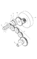
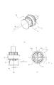
図3〜8は、本実施の形態における駆動伝達装置40の一例を示すものである。以下、駆動伝達装置40の構成について説明する。 3 to 8 show an example of the drive transmission device 40 in the present embodiment. Hereinafter, the configuration of the drive transmission device 40 will be described.
装置本体100には、第1のカップリングである駆動カップリング41、駆動モータ43、伝達ギア44a、ガイド部材46が設けてある。第1のカップリングである駆動カップリング41は、駆動モータ43による動力で回転する。中間転写ユニット12には、第2のカップリングである被駆動カップリング42、付勢部材45、伝達ギア列44bが設けてある。図4に示すように、付勢部材45はバネであり、B方向、即ち装置本体側に向って付勢するものである。被駆動カップリング42は、中間転写ユニット12が装置本体100に装着された状態で、駆動カップリング41と対向する位置に配してある。第2のカップリングである被駆動カップリング42は、第1のカップリングである駆動カップリング41と噛み合うことで、回転可能である。
The apparatus
ガイド部材46は、中間転写ユニット12を着脱する際に、被駆動カップリング42が接するように装置本体に配置してある。さらに、中間転写ユニット12を装置本体100に装着する際の入口側には、被駆動カップリング42を図示M方向へ退避させる斜面46aが設けてある。
The
図4に示すように、伝達ギア44aは、駆動モータ43と駆動カップリング41とを連結するよう配設してあり、伝達ギア列44bは、被駆動カップリング42とカム軸32とを連結するように配設してある。
As shown in FIG. 4, the
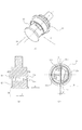
図5に示すように、装置本体に設けられている駆動カップリング41は、凹形状である。さらに、被駆動カップリング42は、凹形状のカップリングに入る凸形状である。ただし、本実施の形態の駆動伝達装置は、上記構成に限定されるものでなく、駆動カップリング41と被駆動カップリング42のうちどちらか一方のカップリングが凹形状、他方のカップリングが凸形状であればよい。
As shown in FIG. 5, the
駆動カップリングは、T字型の第1の係合部41bを有する。更に、凹形状である駆動カップリング41は、内周部に傾斜面41eを有する。凸形状である被駆動カップリング42は、凸部として第2の係合部42aを有する。駆動カップリング41と被駆動カップリング42が噛み合っている状態では、被駆動カップリングの第2の係合部42aが駆動カップリングの内面41aと対向する。同様に、駆動カップリング41と被駆動カップリング42が噛み合っている状態では、駆動カップリングの第1の係合部41bが被駆動カップリングの内面42bと対向する。
The drive coupling has a T-shaped
また、駆動カップリング41と被駆動カップリング42とは単一の位相で噛み合い、駆動を伝達することが可能である。
Further, the
駆動カップリングの傾斜面41eは、駆動カップリング41の内周部に設けられており、中間転写ユニット12が本体に装着された状態では、被駆動カップリング42の第2係合部42aと当接する。被駆動カップリング42は、付勢部材45により、図3に示すように、ユニットの着脱方向であるA方向とは略垂直方向であるB方向で、駆動カップリング41側に付勢されている。B方向は両方のカップリングの回転軸と平行である。
The inclined surface 41e of the drive coupling is provided on the inner peripheral portion of the
駆動モータ43が、制御信号に基き回転駆動し、駆動カップリング41が図示L方向に回転する。図5(d)に示すように駆動カップリング41の回転に伴ない、第1の係合部41bの接触面41cが、第2の係合部の接触面42cと噛み合う。すなわち、駆動モータにより駆動力が伝達される駆動カップリング41の第1の係合部の接触面41cが、被駆動カップリング42の第2の係合部の接触面42c部を押圧する。このことにより、駆動カップリング41から被駆動カップリング42へ回転力が伝達され、被駆動カップリング42は、図示L方向に回転する。この時、回転駆動を伝達し合う41c、42c部は、回転方向の力を伝達する形状になっている。接触面41c及び42cは回転方向Lに対して略垂直な軸線で係合しているので、回転中に被駆動カップリング42を付勢方向であるB方向に反して回転軸方向へ押す力は発生しない。
The
次に、中間転写ユニット12を装置本体100から抜出す(離脱する)場合を説明する。駆動カップリング41と被駆動カップリング42が噛み合っている時は、被駆動カップリングの第2の係合部42aが駆動カップリングの傾斜面41eと接触している。そのため、中間転写ユニット12を装置本体100から引抜く場合は、中間転写ユニット12の離脱方向に働く力(引抜く力)が働くと、傾斜面41eによって被駆動カップリング42に付勢方向Bとは逆行する図示M方向に移動する力が働く。そして被駆動カップリング42が、駆動カップリング41から図示M方向に一時的に退避することとなる。このことによって、第1の係合部41bと第2の係合部42aの係合は解除される。さらに、被駆動カップリング42はガイド部材46と接触し、付勢方向Bとは逆行する図示M方向に退避し続けるため、中間転写ユニット12を装置本体100から抜き出すことができる。
Next, a case where the
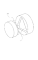
図6、図7を用いて更に詳しく説明する。図6は、中間転写ユニットが離脱開始する前の駆動カップリングと被駆動カップリングの状態、図7は、第1の係合部41bと第2の係合部42aの係合が解除された状態をそれぞれ示している。
This will be described in more detail with reference to FIGS. FIG. 6 shows the state of the drive coupling and the driven coupling before the intermediate transfer unit starts to be detached, and FIG. 7 shows the state where the engagement of the
図6、図7、の(a)は、駆動カップリング41と被駆動カップリング42の状態を示す斜視図であり、(b)は駆動カップリング41と被駆動カップリング42の状態を回転軸と垂直な方向から見た模式図である。図6、7(c)は駆動カップリング41と被駆動カップリング42の状態を回転軸と平行な方向から見た模式図である。
6A and 7B are perspective views showing the state of the
中間転写ユニットが離脱する前は、図6(b)のように、第2の係合部42aの中で中間転写ユニット離脱方向最上流側に位置している被駆動カップリングの第2の係合部(図6で、42fで示す。以下、第2の係合部42f)と駆動カップリングの第1の係合部41bの接触面41cには、回転方向で充分すき間があるように構成してある。
Before the intermediate transfer unit is detached, as shown in FIG. 6B, the second engagement of the driven coupling located on the most upstream side in the intermediate transfer unit removal direction in the second
装置本体からユニットを駆動カップリング41の回転軸に対して垂直な方向へ引抜くと、中間転写ユニットの離脱方向に働く力によって、第2の係合部42fが接触面41cに近づくように、被駆動カップリング42は回動する。この時被駆動カップリング42は、駆動カップリング41の回転軸と異なる位置であって駆動カップリング41と被駆動カップリング42が接触している位置を回動の中心にしている。図6(c)、図7(c)で示すように、第2の係合部42fと第1の係合部41bの間に位置する第2の係合部を、第2の係合部42hとする。第2の係合部42hと接触面41cが接触する位置kを、本実施の形態では回動の中心kとする。
When the unit is pulled out from the apparatus main body in a direction perpendicular to the rotation axis of the
被駆動カップリング42が位置kを中心に回動開始すると、第2の係合部42fは第1の係合部の接触面41cに向かって近づくため、第2の係合部42fと接触面41cの間のすき間は減少する。被駆動カップリング42が回動すると、第2の係合部42aの中で中間転写ユニット離脱方向最下流側に位置している被駆動カップリングの第2の係合部(図7で、42gで示す。以下、第2の係合部42g)が、駆動カップリングの傾斜面41eに沿って中間転写ユニットの離脱方向に移動する。第2の係合部42gが傾斜面41eに沿って移動すると、被駆動カップリング42は図のM方向に退避する。その結果、図7に示すように、第1の係合部と第2の係合部の噛み合いは解除される。即ち、第1の係合部の接触面41cから、第2の係合部の接触面42cが離間する。図7で示すように、第2の係合部42aと第1の係合部41bの係合が解除されるまで、被駆動カップリング42の回転軸が、駆動カップリング41の回転軸に対してユニット離脱方向に移動する距離はβである。
When the driven
次に、装置本体からユニットを駆動カップリング41の回転軸に対して垂直な方向へ引抜く際にユニットの離脱方向に働く力によって、被駆動カップリング42の回転軸が、駆動カップリング41の回転軸よりもユニット離脱方向に移動可能な構造について説明する。図5から解るように、被駆動カップリング42には、駆動カップリング41がはまる十分な広さのある領域がある。つまり、駆動カップリング41と被駆動カップリング42とが噛み合い、回転する場合、すき間ができることになる。
Next, when the unit is pulled out from the apparatus main body in a direction perpendicular to the rotation axis of the
図8で示すように、被駆動カップリング42の回転軸が、駆動カップリング41の回転軸に対してユニット離脱方向に移動可能な最大距離はαでる。
As shown in FIG. 8, the maximum distance that the rotational axis of the driven
本実施の形態の駆動伝達装置では、αはβよりも大きくなるように構成されている。αがβ以上であることによって、被駆動カップリング42が位置kを中心に回動する際に、第2の係合部42fが第1の係合部41bに接触する前に被駆動カップリング42のM方向への退避が完了する。
In the drive transmission device of the present embodiment, α is configured to be larger than β. When α is β or more, when the driven
すなわち、本実施の形態におけるカップリング構成では、中間転写ユニット12を装置本体100から引き出すだけで、被駆動カップリング42と駆動カップリング41の噛み合いが解除され、第1の係合部41bと第2の係合部42aの係合は解除される。
That is, in the coupling configuration according to the present embodiment, the engagement between the driven
上記とは逆に、中間転写ユニット12を画像形成装置100本体へ装着する場合は、被駆動カップリング42が装置本体100のガイド部材46と接触することから、図示M方向に退避する。このことにより、被駆動カップリング42は、駆動カップリング41との噛み合い位置まで円滑に移動することができる。そして、被駆動カップリング42の回転軸と駆動カップリング41の回転軸が略一致した状態では、上述したように、カップリングの回転位相が合ったときに、カップリングが噛み合い、中間転写ユニット12の装置本体100への装着が完了する。
On the contrary, when the
本実施の形態の駆動伝達装置では、単一の位相で噛み合うことで駆動カップリング41から被駆動カップリング42へ駆動を伝達することが可能である。このことから、駆動モータ43の回転量に基いて被駆動カップリング42の位相、即ち、本実施の形態ではカム軸32の位相を制御することができる。
In the drive transmission device of the present embodiment, it is possible to transmit drive from the
また、本実施の形態の駆動伝達装置は凸形状のカップリングの外周部と、凹形状のカップリングの内周部、のうち一方が傾斜面41eを有する構成であればよい。さらに、図11に示すように、被駆動カップリング42の第2の係合部42aも傾斜面を有する構成、即ち、凸形状のカップリングの外周部と、凹形状のカップリングの内周部、双方に傾斜面を有する構成でもよい。駆動カップリング41と被駆動カップリング42の双方に傾斜面を設けると、より円滑に被駆動カップリング42が付勢方向Bとは逆行する図示M方向に退避することが可能である。なお、図12(a)で示す位相の場合は、図12(a)で示す位置kを中心に、被駆動カップリング42は回動し、被駆動カップリング42は傾斜面に沿ってM方向に退避可能である。また図12(b)で示す位相の場合は、被駆動カップリング42は、第2の係合部42aと第1の係合部41bとの接触位置を回動中心にして回動することなく、ユニットの離脱方向に働く力によって傾斜面に沿ってM方向に退避可能である。
Moreover, the drive transmission apparatus of this Embodiment should just be the structure in which one of the outer peripheral part of a convex coupling and the inner peripheral part of a concave coupling has the inclined surface 41e. Furthermore, as shown in FIG. 11, the second
(実施の形態2)
本実施の形態では、駆動カップリング51と被駆動カップリング52が複数の位相で噛み合う駆動伝達装置について説明する。駆動伝達装置以外の構成は、全て実施の形態1と同様である。
(Embodiment 2)
In the present embodiment, a drive transmission device in which the
本体側に設けてある駆動モータで、対象となるユニット側の位相を制御する必要がない場合、図13に示すカップリングの構成でも、同様の効果を得ることができる。例えば、ユニット側のローラ類を所定の方向、速度で回転させるための駆動伝達装置等がこれにあたる。 When it is not necessary to control the phase on the target unit side with the drive motor provided on the main body side, the same effect can be obtained with the coupling configuration shown in FIG. For example, a drive transmission device for rotating the rollers on the unit side at a predetermined direction and speed corresponds to this.
図13中の51は実施の形態1における41に相当する駆動カップリングであり、52は、実施の形態1における42に相当する被駆動カップリングである。本実施の形態のカップリングは、被駆動カップリング52と駆動カップリング51のそれぞれの係合部の形状が実施の形態1のカップリグと異なっている以外は、実施の形態1と同様である。
In FIG. 13, 51 is a drive coupling corresponding to 41 in the first embodiment, and 52 is a driven coupling corresponding to 42 in the first embodiment. The coupling of the present embodiment is the same as that of the first embodiment, except that the shapes of the engaging portions of the driven
図14〜図15に示すように、実施の形態1と同様に、第2の係合部52aと第1の係合部51bの係合が解除されるまでに、被駆動カップリング52の回転軸が、駆動カップリング51の回転軸に対してユニット離脱方向に移動する距離はβである。
As shown in FIGS. 14 to 15, as in the first embodiment, the driven
さらに、図16に示すように、実施の形態1と同様に、被駆動カップリング52の回転軸の駆動カップリング51の回転軸に対するユニット離脱方向に移動可能な最大距離はαである。αがβ以上であることによって、被駆動カップリング52が位置kを中心に回動する際に、第2の係合部52fが第1の係合部51bに接触する前に被駆動カップリング52のM方向への退避が完了する。
Further, as shown in FIG. 16, as in the first embodiment, the maximum distance that the movable shaft of the driven
さらに、図17に示すように、被駆動カップリング52の第2の係合部52aも傾斜面51eを有してもよい。駆動カップリング51と被駆動カップリング52の双方に傾斜面を設けると、より円滑に被駆動カップリング52が付勢方向Bとは逆行する図示M方向に退避することが可能である。
Furthermore, as shown in FIG. 17, the second
(実施の形態3)
本実施の形態では、駆動カップリング61と被駆動カップリング62が複数の位相で噛み合う駆動伝達装置について説明する。駆動伝達装置以外の構成は、全て実施の形態1と同様である。実施の形態2と同様に、本体側に設けてある駆動モータで、対象となるユニット側の位相を制御する必要がない場合に用いることが可能である。
(Embodiment 3)
In the present embodiment, a drive transmission device in which the
図18中の61は実施の形態1における41に相当する駆動カップリングであり、62は、実施の形態1における42に相当する被駆動カップリングである。本実施の形態のカップリングは、被駆動カップリング62と駆動カップリング62のそれぞれの係合部の形状が実施の形態1のカップリグと異なっている以外は、実施の形態1と同様である。
In FIG. 18, 61 is a drive coupling corresponding to 41 in the first embodiment, and 62 is a driven coupling corresponding to 42 in the first embodiment. The coupling of the present embodiment is the same as that of the first embodiment, except that the shapes of the engaging portions of the driven
図19〜図20に示すように、実施の形態1と同様に、第2の係合部62aと第1の係合部61bの係合が解除されるまでに、被駆動カップリング62の回転軸が、駆動カップリング61の回転軸に対してユニット離脱方向に移動する距離はβである。
As shown in FIGS. 19 to 20, as in the first embodiment, the driven
さらに、図21に示すように、実施の形態1と同様に、被駆動カップリング62の回転軸の駆動カップリング61の回転軸に対するユニット離脱方向に移動可能な最大距離はαである。αがβ以上であることによって、被駆動カップリグ62は、駆動カップリング61から円滑に退避することが可能である。
Furthermore, as shown in FIG. 21, the maximum distance that the
さらに、図22に示すように、被駆動カップリング62の第2の係合部62aも傾斜面61eを有してもよい。駆動カップリング61と被駆動カップリング62の双方に傾斜面を設けると、より円滑に被駆動カップリング62が付勢方向Bとは逆行する図示M方向に退避することが可能である。
Furthermore, as shown in FIG. 22, the second engagement portion 62a of the driven
(実施の形態4)
本実施の形態では、実施の形態1で説明した駆動伝達装置で、被駆動カップリング42が円弧面42iを有し、円弧面42iが駆動カップリング41に突き当り、接触する場合の機能を、図23を用いて説明する。図23に示す符号は、実施の形態1に使用した符号と同じである。
(Embodiment 4)
In the present embodiment, in the drive transmission apparatus described in the first embodiment, the driven
被駆動カップリング42は、付勢部材45により、駆動カップリング41側へ付勢されており、円弧面42iが、駆動カップリング41の傾斜面41eと接触し、被駆動カップリング42の軸方向位置が決まる構成となっている。
The driven
ここで、装置本体100に対して、装着した中間転写ユニット12の位置がばらつきの範囲内でズレた場合においても、本構成とすることにより、位置ズレによる偏芯が多少あったとしても、回転力を伝達することができる。
Here, even when the position of the mounted
(その他の実施の形態)
上記の実施の形態では、ユニットとして、中間転写ユニット12と装置本体の間の駆動伝達装置としてカップリングを用いた例をしめしたが、他のユニットやカップリングにも応用可能である。例えば、現像ユニット(カートリッジ)と装置本体の間のカップリングや、実施の形態1のプロセスカートリッジ7と装置本体のカップリングの間である。図24や、図25に示すように、プロセスカートリッジ7が被駆動カップリング42を有する構成でもよい。また、駆動カップリングとして41の形状を示し、被駆動カップリングとして42の形状を示したが、これらの関係は逆であっても実施が可能である。更に、ユニットを装置本体に取り付ける時等に、どちらのカップリングが引っ込む構成であっても、駆動カップリング41と被駆動カップリング42が噛み合に関する機能は、同様に発揮される。
(Other embodiments)
In the above-described embodiment, an example is shown in which a coupling is used as a drive transmission device between the
1 感光ドラム
2 帯電ローラ
3 露光手段
4 現像ユニット
4a〜4d 現像ユニット
5a〜5d クリーニングユニット
7 プロセスカートリッジ
8 クリーニング手段
9 給紙ローラ
10 レジストローラ対
11 給紙カセット
12 中間転写ユニット
12a〜12d (一次)転写手段
12e 中間転写ベルト(中間転写材)
12f 駆動ローラ
12g 従動ローラ
13 給紙装置
14 定着装置
15 二次転写部
16 二次転写手段
20 排紙ローラ対
22 クリーニング手段
23 分離手段
24a〜24d 現像ローラ
25a〜25d 現像剤塗布ローラ
30 一次転写離間手段
31 付勢部材
32 カム軸
33 スライド部材
34 カム部材
40 駆動伝達装置
41、51、61 駆動カップリング
42、52、62 被駆動カップリング
43 駆動モータ
44 伝達ギア
45 付勢部材
100 画像形成装置
S 転写材
A、B、C、D、E、F、L、M 方向
G、H 位相
J、K 位置
DESCRIPTION OF
12f Drive roller 12g Driven
Claims (6)
前記本体カップリングから前記駆動力を受ける回転可能なユニットカップリングを有し、
前記ユニットは、前記装置本体から取り外される際に、前記装置本体に対して前記ユニットカップリングの回転軸線と略垂直な第一方向に移動可能であり、
前記ユニットカップリングは、前記ユニットの本体に対して前記ユニットカップリングの回転軸線と略平行な第二方向に移動可能であり、
前記本体カップリング又は前記ユニットカップリングの一方は、傾斜部を有しており、
前記本体カップリング又は前記ユニットカップリングの他方は、前記傾斜部に当接可能な当接部を有しており、
前記装置本体から前記ユニットが取り外される際に、前記傾斜部と前記当接部とが当接した状態で前記ユニットが前記第一方向に移動することにより、前記ユニットカップリングが、前記本体カップリングから力を受けて前記ユニットの本体に対して前記第二方向に移動し、前記本体カップリングから退避することを特徴とするユニット。 A unit detachably attached to an electrophotographic image forming apparatus main body having a rotatable main body coupling for transmitting a driving force,
A rotatable unit coupling that receives the driving force from the body coupling;
The unit is movable in a first direction substantially perpendicular to a rotation axis of the unit coupling with respect to the apparatus main body when removed from the apparatus main body,
The unit coupling is movable in a second direction substantially parallel to the rotation axis of the unit coupling with respect to the main body of the unit;
One of the main body coupling or the unit coupling has an inclined portion,
The other of the main body coupling or the unit coupling has a contact portion that can contact the inclined portion,
When the unit is removed from the apparatus main body, the unit coupling is moved to the first direction in a state where the inclined portion and the abutting portion are in contact with each other. Receiving the force from the unit, moving in the second direction relative to the main body of the unit, and retreating from the main body coupling.
前記傾斜部又は前記当接部の他方は、凹部の内周に設けられており、
前記凸部が前記凹部に進入した状態で前記ユニットカップリングが前記本体カップリングから前記駆動力を受けることを特徴とする請求項1乃至4のいずれかに記載のユニット。 One of the inclined part or the contact part is provided on the outer periphery of the convex part,
The other of the inclined part or the contact part is provided on the inner periphery of the recess,
The unit according to any one of claims 1 to 4, wherein the unit coupling receives the driving force from the main body coupling in a state where the convex portion enters the concave portion.
前記ユニットカップリングが前記傾斜面に沿って前記本体カップリングから退避することで前記凸部が前記凹部から離れることが可能になるまでに、前記ユニットカップリングの回転軸線が前記第一方向へ移動する距離をβとし、
αはβよりも大きいことを特徴とする請求項1乃至5のいずれかに記載のユニット。 When rotating around the contact position where the main body coupling and the unit coupling are in contact with each other, the rotation axis of the unit coupling is the position different from the rotation axis of the main body coupling. The maximum distance among the distances that can move in the first direction is α,
The axis of rotation of the unit coupling moves in the first direction until the convex portion can be separated from the concave portion by retracting the unit coupling along the inclined surface from the main body coupling. Let β be the distance to
The unit according to claim 1, wherein α is larger than β.
Priority Applications (1)
| Application Number | Priority Date | Filing Date | Title |
|---|---|---|---|
| JP2012004255A JP4979839B2 (en) | 2007-10-30 | 2012-01-12 | Drive transmission device and image forming apparatus |
Applications Claiming Priority (3)
| Application Number | Priority Date | Filing Date | Title |
|---|---|---|---|
| JP2007281830 | 2007-10-30 | ||
| JP2007281830 | 2007-10-30 | ||
| JP2012004255A JP4979839B2 (en) | 2007-10-30 | 2012-01-12 | Drive transmission device and image forming apparatus |
Related Parent Applications (1)
| Application Number | Title | Priority Date | Filing Date |
|---|---|---|---|
| JP2008278424A Division JP4912381B2 (en) | 2007-10-30 | 2008-10-29 | Drive transmission device and image forming apparatus |
Related Child Applications (1)
| Application Number | Title | Priority Date | Filing Date |
|---|---|---|---|
| JP2012094000A Division JP2012145963A (en) | 2007-10-30 | 2012-04-17 | Drive transmission apparatus, and image forming apparatus |
Publications (2)
| Publication Number | Publication Date |
|---|---|
| JP2012068684A JP2012068684A (en) | 2012-04-05 |
| JP4979839B2 true JP4979839B2 (en) | 2012-07-18 |
Family
ID=40866150
Family Applications (10)
| Application Number | Title | Priority Date | Filing Date |
|---|---|---|---|
| JP2012004255A Active JP4979839B2 (en) | 2007-10-30 | 2012-01-12 | Drive transmission device and image forming apparatus |
| JP2012094000A Pending JP2012145963A (en) | 2007-10-30 | 2012-04-17 | Drive transmission apparatus, and image forming apparatus |
| JP2013062767A Active JP5559379B2 (en) | 2007-10-30 | 2013-03-25 | A unit that can be attached to and detached from the electrophotographic image forming apparatus main body. |
| JP2014118107A Pending JP2014157383A (en) | 2007-10-30 | 2014-06-06 | Drive transmission apparatus, and image forming apparatus |
| JP2016017480A Active JP6080992B2 (en) | 2007-10-30 | 2016-02-01 | Electrophotographic image forming apparatus and unit used in electrophotographic image forming apparatus |
| JP2017004660A Active JP6336144B2 (en) | 2007-10-30 | 2017-01-13 | Image forming apparatus |
| JP2018085296A Active JP6548777B2 (en) | 2007-10-30 | 2018-04-26 | Drive transmission device and image forming apparatus |
| JP2019112982A Active JP6849739B2 (en) | 2007-10-30 | 2019-06-18 | Drive transmission device and image forming device |
| JP2020066323A Active JP6862590B2 (en) | 2007-10-30 | 2020-04-01 | Drive transmission device and image forming device |
| JP2021063162A Active JP7081018B2 (en) | 2007-10-30 | 2021-04-01 | Drive transmission device and image forming device |
Family Applications After (9)
| Application Number | Title | Priority Date | Filing Date |
|---|---|---|---|
| JP2012094000A Pending JP2012145963A (en) | 2007-10-30 | 2012-04-17 | Drive transmission apparatus, and image forming apparatus |
| JP2013062767A Active JP5559379B2 (en) | 2007-10-30 | 2013-03-25 | A unit that can be attached to and detached from the electrophotographic image forming apparatus main body. |
| JP2014118107A Pending JP2014157383A (en) | 2007-10-30 | 2014-06-06 | Drive transmission apparatus, and image forming apparatus |
| JP2016017480A Active JP6080992B2 (en) | 2007-10-30 | 2016-02-01 | Electrophotographic image forming apparatus and unit used in electrophotographic image forming apparatus |
| JP2017004660A Active JP6336144B2 (en) | 2007-10-30 | 2017-01-13 | Image forming apparatus |
| JP2018085296A Active JP6548777B2 (en) | 2007-10-30 | 2018-04-26 | Drive transmission device and image forming apparatus |
| JP2019112982A Active JP6849739B2 (en) | 2007-10-30 | 2019-06-18 | Drive transmission device and image forming device |
| JP2020066323A Active JP6862590B2 (en) | 2007-10-30 | 2020-04-01 | Drive transmission device and image forming device |
| JP2021063162A Active JP7081018B2 (en) | 2007-10-30 | 2021-04-01 | Drive transmission device and image forming device |
Country Status (1)
| Country | Link |
|---|---|
| JP (10) | JP4979839B2 (en) |
Families Citing this family (8)
| Publication number | Priority date | Publication date | Assignee | Title |
|---|---|---|---|---|
| JP4979839B2 (en) * | 2007-10-30 | 2012-07-18 | キヤノン株式会社 | Drive transmission device and image forming apparatus |
| JP5506236B2 (en) * | 2009-04-30 | 2014-05-28 | キヤノン株式会社 | Cartridge and electrophotographic image forming apparatus |
| JP6379745B2 (en) | 2014-07-01 | 2018-08-29 | ブラザー工業株式会社 | Image forming apparatus |
| CN105467805B (en) | 2014-09-30 | 2020-09-08 | 兄弟工业株式会社 | Image forming apparatus with a toner supply unit |
| JP6501484B2 (en) * | 2014-10-22 | 2019-04-17 | キヤノン株式会社 | Image forming device |
| US9964911B2 (en) | 2015-03-20 | 2018-05-08 | Canon Kabushiki Kaisha | Driving force transmitting apparatus and image forming apparatus |
| JP6697707B2 (en) * | 2015-12-09 | 2020-05-27 | 株式会社リコー | Drive transmission device and image forming apparatus |
| JP6653082B2 (en) * | 2016-05-23 | 2020-02-26 | 株式会社リコー | Drive transmission device and image forming apparatus |
Family Cites Families (26)
| Publication number | Priority date | Publication date | Assignee | Title |
|---|---|---|---|---|
| JPH07113378B2 (en) * | 1985-11-27 | 1995-12-06 | 松井ワルターシャイド株式会社 | Detachable coupling device |
| JPH01299320A (en) * | 1988-05-26 | 1989-12-04 | Fujitsu Ltd | Shaft connecting mechanism |
| GB2239303B (en) * | 1989-12-22 | 1994-01-12 | Xerox Corp | Drive coupling |
| JP3347361B2 (en) * | 1992-06-12 | 2002-11-20 | キヤノン株式会社 | Image forming device |
| JPH09179473A (en) * | 1995-12-21 | 1997-07-11 | Ricoh Co Ltd | Image forming device |
| JP3372772B2 (en) * | 1996-07-22 | 2003-02-04 | キヤノン株式会社 | Process cartridge and electrophotographic image forming apparatus |
| JPH11258966A (en) * | 1998-03-12 | 1999-09-24 | Casio Electronics Co Ltd | Image forming device |
| JP2000170783A (en) * | 1998-12-03 | 2000-06-20 | Canon Inc | Torque transmitting mechanism, sheet feeding device, and image forming device |
| JP2001296718A (en) * | 2000-04-17 | 2001-10-26 | Matsushita Electric Ind Co Ltd | Color image forming device |
| JP4514170B2 (en) * | 2000-07-11 | 2010-07-28 | キヤノン株式会社 | Coupling device and image forming apparatus having the same |
| KR100381601B1 (en) * | 2001-09-26 | 2003-04-26 | 삼성전자주식회사 | coupling apparatus and process cartridge and electrophotographic printer having the same |
| JP2005076873A (en) * | 2003-09-03 | 2005-03-24 | Ricoh Co Ltd | Coupling device and image formation device including the same |
| JP2005157112A (en) * | 2003-11-27 | 2005-06-16 | Canon Inc | Image forming apparatus |
| JP5049486B2 (en) * | 2004-12-13 | 2012-10-17 | キヤノン株式会社 | Image forming apparatus and image carrier unit applied thereto |
| JP4530357B2 (en) * | 2005-02-15 | 2010-08-25 | 京セラミタ株式会社 | Shaft joint and image forming apparatus having the same |
| JP4784126B2 (en) * | 2005-03-29 | 2011-10-05 | 富士ゼロックス株式会社 | Photostatic device and image forming apparatus using the same |
| JP4704136B2 (en) * | 2005-05-31 | 2011-06-15 | 株式会社リコー | Coupling device and image forming apparatus provided with coupling device |
| JP4765501B2 (en) * | 2005-09-14 | 2011-09-07 | ブラザー工業株式会社 | Image forming apparatus and developing cartridge |
| JP2007206596A (en) * | 2006-02-06 | 2007-08-16 | Canon Inc | Electrophotographic image forming apparatus |
| JP4939865B2 (en) * | 2006-07-31 | 2012-05-30 | 株式会社リコー | Coupling device and image forming apparatus provided with coupling device |
| KR101305527B1 (en) * | 2006-11-22 | 2013-09-05 | 삼성전자주식회사 | Image forming apparatus and power transmitting apparatus therefor |
| JP4498407B2 (en) * | 2006-12-22 | 2010-07-07 | キヤノン株式会社 | Process cartridge, electrophotographic image forming apparatus, and electrophotographic photosensitive drum unit |
| JP2009092812A (en) * | 2007-10-05 | 2009-04-30 | Ricoh Co Ltd | Image forming apparatus |
| JP4912381B2 (en) * | 2007-10-30 | 2012-04-11 | キヤノン株式会社 | Drive transmission device and image forming apparatus |
| JP4979839B2 (en) * | 2007-10-30 | 2012-07-18 | キヤノン株式会社 | Drive transmission device and image forming apparatus |
| JP2012004255A (en) * | 2010-06-15 | 2012-01-05 | Panasonic Corp | Semiconductor device |
-
2012
- 2012-01-12 JP JP2012004255A patent/JP4979839B2/en active Active
- 2012-04-17 JP JP2012094000A patent/JP2012145963A/en active Pending
-
2013
- 2013-03-25 JP JP2013062767A patent/JP5559379B2/en active Active
-
2014
- 2014-06-06 JP JP2014118107A patent/JP2014157383A/en active Pending
-
2016
- 2016-02-01 JP JP2016017480A patent/JP6080992B2/en active Active
-
2017
- 2017-01-13 JP JP2017004660A patent/JP6336144B2/en active Active
-
2018
- 2018-04-26 JP JP2018085296A patent/JP6548777B2/en active Active
-
2019
- 2019-06-18 JP JP2019112982A patent/JP6849739B2/en active Active
-
2020
- 2020-04-01 JP JP2020066323A patent/JP6862590B2/en active Active
-
2021
- 2021-04-01 JP JP2021063162A patent/JP7081018B2/en active Active
Also Published As
| Publication number | Publication date |
|---|---|
| JP2021105733A (en) | 2021-07-26 |
| JP5559379B2 (en) | 2014-07-23 |
| JP2013127649A (en) | 2013-06-27 |
| JP2020101840A (en) | 2020-07-02 |
| JP7081018B2 (en) | 2022-06-06 |
| JP6862590B2 (en) | 2021-04-21 |
| JP2014157383A (en) | 2014-08-28 |
| JP2018124577A (en) | 2018-08-09 |
| JP2019148837A (en) | 2019-09-05 |
| JP2016105198A (en) | 2016-06-09 |
| JP2012145963A (en) | 2012-08-02 |
| JP6849739B2 (en) | 2021-03-31 |
| JP6336144B2 (en) | 2018-06-06 |
| JP6080992B2 (en) | 2017-02-15 |
| JP2017072862A (en) | 2017-04-13 |
| JP6548777B2 (en) | 2019-07-24 |
| JP2012068684A (en) | 2012-04-05 |
Similar Documents
| Publication | Publication Date | Title |
|---|---|---|
| JP4912381B2 (en) | Drive transmission device and image forming apparatus | |
| JP6336144B2 (en) | Image forming apparatus | |
| US11144006B2 (en) | Image forming apparatus | |
| JP4579394B2 (en) | Intermediate transfer unit and image forming apparatus |
Legal Events
| Date | Code | Title | Description |
|---|---|---|---|
| A621 | Written request for application examination |
Free format text: JAPANESE INTERMEDIATE CODE: A621 Effective date: 20120208 |
|
| TRDD | Decision of grant or rejection written | ||
| A01 | Written decision to grant a patent or to grant a registration (utility model) |
Free format text: JAPANESE INTERMEDIATE CODE: A01 Effective date: 20120321 |
|
| A01 | Written decision to grant a patent or to grant a registration (utility model) |
Free format text: JAPANESE INTERMEDIATE CODE: A01 |
|
| A61 | First payment of annual fees (during grant procedure) |
Free format text: JAPANESE INTERMEDIATE CODE: A61 Effective date: 20120417 |
|
| FPAY | Renewal fee payment (event date is renewal date of database) |
Free format text: PAYMENT UNTIL: 20150427 Year of fee payment: 3 |
|
| R151 | Written notification of patent or utility model registration |
Ref document number: 4979839 Country of ref document: JP Free format text: JAPANESE INTERMEDIATE CODE: R151 |