JP4979034B2 - Stent graft - Google Patents
Stent graft Download PDFInfo
- Publication number
- JP4979034B2 JP4979034B2 JP2009524706A JP2009524706A JP4979034B2 JP 4979034 B2 JP4979034 B2 JP 4979034B2 JP 2009524706 A JP2009524706 A JP 2009524706A JP 2009524706 A JP2009524706 A JP 2009524706A JP 4979034 B2 JP4979034 B2 JP 4979034B2
- Authority
- JP
- Japan
- Prior art keywords
- stent graft
- tubular body
- tubes
- fenestrations
- stent
- Prior art date
- Legal status (The legal status is an assumption and is not a legal conclusion. Google has not performed a legal analysis and makes no representation as to the accuracy of the status listed.)
- Active
Links
- 239000000560 biocompatible material Substances 0.000 claims abstract description 4
- RVTZCBVAJQQJTK-UHFFFAOYSA-N oxygen(2-);zirconium(4+) Chemical compound [O-2].[O-2].[Zr+4] RVTZCBVAJQQJTK-UHFFFAOYSA-N 0.000 claims description 4
- 230000003014 reinforcing effect Effects 0.000 claims description 2
- 210000000709 aorta Anatomy 0.000 description 8
- 241001465754 Metazoa Species 0.000 description 3
- 230000001919 adrenal effect Effects 0.000 description 2
- 230000017531 blood circulation Effects 0.000 description 2
- 210000004204 blood vessel Anatomy 0.000 description 2
- 210000002434 celiac artery Anatomy 0.000 description 2
- 230000037431 insertion Effects 0.000 description 2
- 238000003780 insertion Methods 0.000 description 2
- 210000001363 mesenteric artery superior Anatomy 0.000 description 2
- 210000004100 adrenal gland Anatomy 0.000 description 1
- 230000036772 blood pressure Effects 0.000 description 1
- 230000007717 exclusion Effects 0.000 description 1
- 210000003734 kidney Anatomy 0.000 description 1
- 210000002254 renal artery Anatomy 0.000 description 1
Images


Classifications
-
- A—HUMAN NECESSITIES
- A61—MEDICAL OR VETERINARY SCIENCE; HYGIENE
- A61F—FILTERS IMPLANTABLE INTO BLOOD VESSELS; PROSTHESES; DEVICES PROVIDING PATENCY TO, OR PREVENTING COLLAPSING OF, TUBULAR STRUCTURES OF THE BODY, e.g. STENTS; ORTHOPAEDIC, NURSING OR CONTRACEPTIVE DEVICES; FOMENTATION; TREATMENT OR PROTECTION OF EYES OR EARS; BANDAGES, DRESSINGS OR ABSORBENT PADS; FIRST-AID KITS
- A61F2/00—Filters implantable into blood vessels; Prostheses, i.e. artificial substitutes or replacements for parts of the body; Appliances for connecting them with the body; Devices providing patency to, or preventing collapsing of, tubular structures of the body, e.g. stents
- A61F2/02—Prostheses implantable into the body
- A61F2/04—Hollow or tubular parts of organs, e.g. bladders, tracheae, bronchi or bile ducts
- A61F2/06—Blood vessels
- A61F2/07—Stent-grafts
-
- A—HUMAN NECESSITIES
- A61—MEDICAL OR VETERINARY SCIENCE; HYGIENE
- A61F—FILTERS IMPLANTABLE INTO BLOOD VESSELS; PROSTHESES; DEVICES PROVIDING PATENCY TO, OR PREVENTING COLLAPSING OF, TUBULAR STRUCTURES OF THE BODY, e.g. STENTS; ORTHOPAEDIC, NURSING OR CONTRACEPTIVE DEVICES; FOMENTATION; TREATMENT OR PROTECTION OF EYES OR EARS; BANDAGES, DRESSINGS OR ABSORBENT PADS; FIRST-AID KITS
- A61F2/00—Filters implantable into blood vessels; Prostheses, i.e. artificial substitutes or replacements for parts of the body; Appliances for connecting them with the body; Devices providing patency to, or preventing collapsing of, tubular structures of the body, e.g. stents
- A61F2/82—Devices providing patency to, or preventing collapsing of, tubular structures of the body, e.g. stents
- A61F2/86—Stents in a form characterised by the wire-like elements; Stents in the form characterised by a net-like or mesh-like structure
- A61F2/89—Stents in a form characterised by the wire-like elements; Stents in the form characterised by a net-like or mesh-like structure the wire-like elements comprising two or more adjacent rings flexibly connected by separate members
-
- A—HUMAN NECESSITIES
- A61—MEDICAL OR VETERINARY SCIENCE; HYGIENE
- A61F—FILTERS IMPLANTABLE INTO BLOOD VESSELS; PROSTHESES; DEVICES PROVIDING PATENCY TO, OR PREVENTING COLLAPSING OF, TUBULAR STRUCTURES OF THE BODY, e.g. STENTS; ORTHOPAEDIC, NURSING OR CONTRACEPTIVE DEVICES; FOMENTATION; TREATMENT OR PROTECTION OF EYES OR EARS; BANDAGES, DRESSINGS OR ABSORBENT PADS; FIRST-AID KITS
- A61F2/00—Filters implantable into blood vessels; Prostheses, i.e. artificial substitutes or replacements for parts of the body; Appliances for connecting them with the body; Devices providing patency to, or preventing collapsing of, tubular structures of the body, e.g. stents
- A61F2/02—Prostheses implantable into the body
- A61F2/04—Hollow or tubular parts of organs, e.g. bladders, tracheae, bronchi or bile ducts
- A61F2/06—Blood vessels
- A61F2002/061—Blood vessels provided with means for allowing access to secondary lumens
-
- A—HUMAN NECESSITIES
- A61—MEDICAL OR VETERINARY SCIENCE; HYGIENE
- A61F—FILTERS IMPLANTABLE INTO BLOOD VESSELS; PROSTHESES; DEVICES PROVIDING PATENCY TO, OR PREVENTING COLLAPSING OF, TUBULAR STRUCTURES OF THE BODY, e.g. STENTS; ORTHOPAEDIC, NURSING OR CONTRACEPTIVE DEVICES; FOMENTATION; TREATMENT OR PROTECTION OF EYES OR EARS; BANDAGES, DRESSINGS OR ABSORBENT PADS; FIRST-AID KITS
- A61F2/00—Filters implantable into blood vessels; Prostheses, i.e. artificial substitutes or replacements for parts of the body; Appliances for connecting them with the body; Devices providing patency to, or preventing collapsing of, tubular structures of the body, e.g. stents
- A61F2/02—Prostheses implantable into the body
- A61F2/04—Hollow or tubular parts of organs, e.g. bladders, tracheae, bronchi or bile ducts
- A61F2/06—Blood vessels
- A61F2/07—Stent-grafts
- A61F2002/075—Stent-grafts the stent being loosely attached to the graft material, e.g. by stitching
-
- A—HUMAN NECESSITIES
- A61—MEDICAL OR VETERINARY SCIENCE; HYGIENE
- A61F—FILTERS IMPLANTABLE INTO BLOOD VESSELS; PROSTHESES; DEVICES PROVIDING PATENCY TO, OR PREVENTING COLLAPSING OF, TUBULAR STRUCTURES OF THE BODY, e.g. STENTS; ORTHOPAEDIC, NURSING OR CONTRACEPTIVE DEVICES; FOMENTATION; TREATMENT OR PROTECTION OF EYES OR EARS; BANDAGES, DRESSINGS OR ABSORBENT PADS; FIRST-AID KITS
- A61F2220/00—Fixations or connections for prostheses classified in groups A61F2/00 - A61F2/26 or A61F2/82 or A61F9/00 or A61F11/00 or subgroups thereof
- A61F2220/0025—Connections or couplings between prosthetic parts, e.g. between modular parts; Connecting elements
- A61F2220/0075—Connections or couplings between prosthetic parts, e.g. between modular parts; Connecting elements sutured, ligatured or stitched, retained or tied with a rope, string, thread, wire or cable
-
- A—HUMAN NECESSITIES
- A61—MEDICAL OR VETERINARY SCIENCE; HYGIENE
- A61F—FILTERS IMPLANTABLE INTO BLOOD VESSELS; PROSTHESES; DEVICES PROVIDING PATENCY TO, OR PREVENTING COLLAPSING OF, TUBULAR STRUCTURES OF THE BODY, e.g. STENTS; ORTHOPAEDIC, NURSING OR CONTRACEPTIVE DEVICES; FOMENTATION; TREATMENT OR PROTECTION OF EYES OR EARS; BANDAGES, DRESSINGS OR ABSORBENT PADS; FIRST-AID KITS
- A61F2250/00—Special features of prostheses classified in groups A61F2/00 - A61F2/26 or A61F2/82 or A61F9/00 or A61F11/00 or subgroups thereof
- A61F2250/0014—Special features of prostheses classified in groups A61F2/00 - A61F2/26 or A61F2/82 or A61F9/00 or A61F11/00 or subgroups thereof having different values of a given property or geometrical feature, e.g. mechanical property or material property, at different locations within the same prosthesis
- A61F2250/0039—Special features of prostheses classified in groups A61F2/00 - A61F2/26 or A61F2/82 or A61F9/00 or A61F11/00 or subgroups thereof having different values of a given property or geometrical feature, e.g. mechanical property or material property, at different locations within the same prosthesis differing in diameter
Landscapes
- Health & Medical Sciences (AREA)
- Gastroenterology & Hepatology (AREA)
- Pulmonology (AREA)
- Cardiology (AREA)
- Oral & Maxillofacial Surgery (AREA)
- Transplantation (AREA)
- Engineering & Computer Science (AREA)
- Biomedical Technology (AREA)
- Heart & Thoracic Surgery (AREA)
- Vascular Medicine (AREA)
- Life Sciences & Earth Sciences (AREA)
- Animal Behavior & Ethology (AREA)
- General Health & Medical Sciences (AREA)
- Public Health (AREA)
- Veterinary Medicine (AREA)
- Prostheses (AREA)
- Materials For Medical Uses (AREA)
Abstract
Description
本発明は医療装置に関し、より特定的に、血管内に展開するためのステントグラフトに関する。特に、本発明は分岐したステントグラフトの構成に関する。 The present invention relates to medical devices, and more particularly to stent grafts for deployment in blood vessels. In particular, the present invention relates to a bifurcated stent graft configuration.
発明の背景
脈管の患部をバイパスするために血管内に展開するためのステントグラフトが開発されており、そのようなステントグラフトは、大動脈などの身体の脈管内に展開され得る。大動脈などの身体の脈管から分岐がある場合、分岐脈管への流れを可能にするためにステントグラフト内に分岐を有することが望ましい。
BACKGROUND OF THE INVENTION Stent grafts have been developed for deployment in blood vessels to bypass diseased vessels, and such stent grafts can be deployed in body vessels such as the aorta. Where there is a branch from a body vessel such as the aorta, it is desirable to have a branch in the stent graft to allow flow to the branch vessel.
大動脈の腎臓および副腎領域では、延在する分岐を有するステントグラフトの使用は困難であり、内部分岐を有するステントグラフトが提案されており、この中にサイドアーム延長部を展開して、ステントグラフトの内部分岐から分岐脈管内に延在させることができる。 In the aortic kidney and adrenal glands, it is difficult to use stent grafts with extended branches, and stent grafts with internal branches have been proposed, in which side arm extensions can be deployed to separate the stent graft from internal branches. It can extend into the branch vessel.
しかし、そのような内部脚部にカテーテルを挿入することは困難であり得る。 However, it can be difficult to insert a catheter into such an internal leg.
発明の要約
本発明は、特に複数の接続すべき分岐がある場合にカテーテル挿入を容易にする構造を有するステントグラフトを提供することを目的とする。本発明の好ましい実施例は、ステントグラフトを腹腔動脈、上腸間膜動脈および腎動脈内に展開するためにステントグラフトを大動脈の腎臓および副腎領域内に展開することに関して特に説明される。しかし、本発明はそのように限定されず、胸弓内などの主なグラフトから分岐がある他の領域にも適用可能である。
SUMMARY OF THE INVENTION It is an object of the present invention to provide a stent graft having a structure that facilitates catheter insertion, particularly when there are multiple branches to be connected. The preferred embodiment of the present invention is specifically described with respect to deploying the stent graft in the renal and adrenal regions of the aorta to deploy the stent graft into the celiac, superior mesenteric and renal arteries. However, the present invention is not so limited and is applicable to other areas where there is a branch from the main graft, such as within the arch.
本明細書全体にわたって、大動脈、展開装置または人工器官の一部に関して遠位という用語は、血流方向において心臓からより遠い大動脈、展開装置または人工器官の端であり、近位という用語は、心臓により近い大動脈、展開装置の一部または人工器官の端を意味する。他の脈管に応用された場合、尾側および頭側などの同様の用語を理解すべきである。 Throughout this specification, the term distal with respect to the part of the aorta, deployment device or prosthesis is the end of the aorta, deployment device or prosthesis farther from the heart in the direction of blood flow and the term proximal is the heart Means the aorta closer, the part of the deployment device or the end of the prosthesis. When applied to other vessels, similar terms such as caudal and cranial should be understood.
したがって、1つの形態では、これは唯一のまたは最も広範な形態とは限らないが、本発明の局面は、ステントグラフトであって、生体適合性材料製の管状体と、管状体内の少なくとも2つの開窓とを含み、少なくとも2つの開窓は互いに隣接しており、さらに、各開窓から管状体内に延在する管を含み、これらの管は接合され、ステントグラフトの管状体内でより大きい直径の単一の管に開口する、ステントグラフトを提供する。 Thus, in one form, this is not the only or most extensive form, but an aspect of the invention is a stent graft comprising a tubular body made of biocompatible material and at least two openings in the tubular body. And at least two fenestrations are adjacent to each other, and further include tubes extending from each fenestration into the tubular body, the tubes being joined and having a larger diameter unit within the stent graft tubular body. A stent graft is provided that opens into a tube.
開窓から延在してより大きい単一の管に開口する少なくとも2本の管を有することによって、たとえば腕から入れることによって内部に誘導ワイヤを展開可能なより大きい管を与えて、より大きい管を、続いてより小さい管の一方または両方を入れることにより、カテーテル挿入が容易であることが理解されるであろう。より大きい直径の単一の管はしたがって、カテーテルの誘導装置として作用し、少なくとも2本の管に対する漏斗機能を与える。 By having at least two tubes extending from the fenestration and opening into a larger single tube, giving a larger tube in which a guide wire can be deployed, for example by entering from an arm, a larger tube It will be appreciated that catheter insertion can be facilitated by subsequently inserting one or both of the smaller tubes. The larger diameter single tube thus acts as a catheter guide and provides a funnel function for at least two tubes.
本発明の好ましい実施例に係るステントグラフトの副腎領域での使用が意図される場合、管は、開窓からステントグラフトの近端に向かって延在する。 When intended for use in the adrenal region of a stent graft according to a preferred embodiment of the present invention, the tube extends from the fenestration toward the proximal end of the stent graft.
好ましい実施例では、管状体はテーパー部を有し、開窓はテーパー部に設けられる。腹腔動脈および上腸間膜動脈の領域では、大動脈は、これらの主要な分岐脈管が大動脈から延在するにつれてテーパー状になり、ステントグラフトのテーパリングはステントグラフト内の良好な血流および血圧の維持を助ける。 In a preferred embodiment, the tubular body has a tapered portion, and the fenestration is provided in the tapered portion. In the region of the celiac and superior mesenteric arteries, the aorta tapers as these major branch vessels extend from the aorta, and the stent graft tapering maintains good blood flow and blood pressure within the stent graft. Help.
より大きい直径の単一の管は好ましくは管状体の壁に接合されているため、ステントグラフトを通して内腔の1つの側に保持され、誘導ワイヤを用いて比較的容易に配置され得る。 The larger diameter single tube is preferably joined to the wall of the tubular body so that it can be held through the stent graft on one side of the lumen and relatively easily deployed using a guide wire.
1つの実施例では、少なくとも2本の管は、管状体の周りを横方向に隣接する位置に、または管状体に沿って長手方向に隣接する位置に延在し得る。 In one example, the at least two tubes may extend to a laterally adjacent location around the tubular body or to a longitudinally adjacent location along the tubular body.
ある実施例では、3つの開窓、および3つの開窓から単一のより大きい管に延在する3本の管があり得る。 In certain embodiments, there may be three fenestrations and three tubes extending from the three fenestrations to a single larger tube.
開窓の少なくとも1つ、好ましくは各々は、その周りに少なくとも1つのニチノールワイヤの補強リングを含み得る。 At least one, preferably each, of the fenestrations may include at least one reinforcing ring of nitinol wire around it.
好ましくは、より大きい直径の単一の管はジグザグの自己拡張型ステントを含み、および/または開窓から延在する管の少なくとも1本、好ましくは各々も、ジグザグの自己拡張型ステントを含む。ジグザグの自己拡張型ステントは、いずれの場合も外部にあり得る。 Preferably, the larger diameter single tube comprises a zigzag self-expanding stent and / or at least one of the tubes extending from the fenestration, preferably each also comprises a zigzag self-expanding stent. The zigzag self-expanding stent can be external in either case.
本発明の好ましい実施例が、添付の図面を参照して一例としてのみ説明される。 Preferred embodiments of the present invention will now be described by way of example only with reference to the accompanying drawings.
詳細な説明
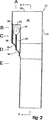
図面、特にステントグラフトの第1の実施例を示す図1から図4をより詳細に見ると、ステントグラフト10が、テーパー状の中央領域14を含む生体適合性材料製の管状体12を有することが示されるであろう。管状体はステント16によって支持される。好ましくは、これらのステントは自己拡張型GianturcoジグザグZステントであるが、他の形態のステントが含まれるか用いられてもよい。
Detailed description of the drawings, particularly FIGS. 1 to 4 showing a first embodiment of a stent graft, shows in more detail a
テーパー領域14には、自身の周縁部の周りの弾性ニチノールワイヤ22によって規定される少なくとも2つの開窓18および20がある。
In the
図2に示されるように、開窓18および20からステントグラフト10の近端28に向かって上方に延在する1対の管24および26があり、これらの管24および26は単一のより大きい管30に開口し、これはステントグラフト10の内腔32に開口する。より大きい管30は縫合34によって管状体12に接続され、ジグザグの自己拡張型ステント36がより大きい胴体の外側の周りに展開されて、一旦人体または動物体内に展開され放されると開存性を与えるか維持する。
As shown in FIG. 2, there is a pair of
図1および図2では1対の管24および26が示されているが、このような管が2本よりも多く設けられてもよい。
Although a pair of
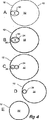
図4は、図1から図3に示されるステントグラフトのさまざまな断面図である。
ステントグラフトの上面図が図4Aに示される。ステントグラフト管状体12は、単一の管30に開口する少なくとも2本の管24および26を有し、単一の管30は34で管状の壁12に接合されているため、管状体の1つの側に保持される。
FIG. 4 is various cross-sectional views of the stent graft shown in FIGS.
A top view of the stent graft is shown in FIG. 4A. The stent-graft
図4Bは、図2に示される高さBにおける断面図である。より大きい管30は断面で示され、より小さい管24および26は、ステントグラフト管状体12の内腔32内で、そこから下方に延在していることが示される。
4B is a cross-sectional view at the height B shown in FIG. The
図4Cは、図2に示される高さCにおける断面図である。より小さい管24および26は、ステントグラフト管状体12の内腔32内に断面で示される。
4C is a cross-sectional view at the height C shown in FIG.
図4Dは、図2に示される高さDにおける断面図である。管状体12はテーパー部14内にあるため管状体の直径が小さくなっていることが示され、断面で示されるのは管24のみである。
4D is a cross-sectional view at the height D shown in FIG. Since the
さらに遠位で、図4に示されるような断面Eでは、管状体は実質的に円形であるが、さらに上方よりも直径が小さい。 Further distally, in cross-section E as shown in FIG. 4, the tubular body is substantially circular, but still smaller in diameter than above.
より小さい管24および26の内部に1つ以上の自己拡張型ステントを設けて、一旦ステントグラフトが展開されるとこれらの管の開存性を維持することもできる。
One or more self-expanding stents can be provided within the
次に、本発明に係るステントグラフトの代替実施例を示す図5から図8を参照して、ステントグラフト40が、テーパー状の中央領域44を含む管状体42を有することが示されるであろう。管状体はステント46によって支持される。好ましくは、これらのステントは自己拡張型GianturcoジグザグZステントであるが、他の形態のステントが含まれる
か用いられてもよい。
Referring now to FIGS. 5-8 illustrating an alternative embodiment of a stent graft according to the present invention, it will be shown that the
テーパー領域44には、自身の周縁部の周りの弾性ニチノールワイヤ52によって規定される少なくとも2つの開窓48および50がある。
The tapered
図6および図7に示されるように、開窓48および50からステントグラフト40の近端68に向かって上方に延在する1対の管54および55があり、これらの管54および55は単一のより大きい管60に開口し、これはステントグラフト40の内腔62に開口する。より大きい管60は縫合64によって管状体42に接続される。
As shown in FIGS. 6 and 7, there is a pair of
開示された第1の実施例と同様に、本実施例も2本の管54、55よりも多い管を有してもよい。
Similar to the first disclosed embodiment, this embodiment may have more than two
特に図7に示されるように、より大きい管60の外側の周りにはジグザグの自己拡張型ステント66が展開されており、一旦人体または動物体内に展開され放されると開存性を与えるか維持する。開窓48および50から延在するより小さい管54および55も、自身の外側の周りにジグザグの自己拡張型ステント57が展開されており、一旦ステントグラフトが人体または動物体内に展開され放されるとこれらの管の開存性を維持する。
In particular, as shown in FIG. 7, a zigzag self-expanding
図8は、図5から図7に示されるステントグラフトのさまざまな断面図である。
ステントグラフトの上面図が図8Aに示される。ステントグラフト管状体42は、単一の管60に開口する少なくとも2本の管54および55を有し、単一の管60は64で管状の壁42に接合されているため、管状体の1つの側に保持される。
FIG. 8 is various cross-sectional views of the stent graft shown in FIGS.
A top view of the stent graft is shown in FIG. 8A. The stent-
図8Bは、図6に示される高さBにおける断面図である。より大きい管60は断面で示され、より小さい管54および55は、ステントグラフト管状体42の内腔62内で、そこから下方に延在していることが示される。
FIG. 8B is a cross-sectional view at height B shown in FIG.
図8Cは、図6に示される高さCにおける断面図である。より小さい管54および55は、ステントグラフト管状体42の内腔62内に断面で示される。
FIG. 8C is a cross-sectional view at the height C shown in FIG.
図8Dは、図6に示される高さDにおける断面図である。管状体42はテーパー部44内にあるため管状体の直径が小さくなっていることが示され、管54および55の一部が断面で示される。
FIG. 8D is a cross-sectional view at the height D shown in FIG.
図8に示されるような断面Eにおけるさらに遠位では、管状体は実質的に円形であるが、さらに近位よりも直径が小さい。 Further distal in cross-section E as shown in FIG. 8, the tubular body is substantially circular but is smaller in diameter than proximal.
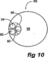
図9は、本発明に係るステントグラフトの別の実施例を示す。本実施例では、ステントグラフト80は、ステントによって支持される管状体82を有する。本実施例では、少なくとも3つの開窓84、86および88、ならびにそれぞれ開窓84、86および88から延在する3本の管90、92および94がある。本実施例では、開窓84、86および88は実質的に三角形のパターンに配置される。
FIG. 9 shows another embodiment of a stent graft according to the present invention. In this embodiment, the
図10に示されるように、3本の管90、92および94は、管状体80の内腔98内で単一のより大きい管96に開口する。
As shown in FIG. 10, the three
本明細書全体にわたって本発明の範囲に関してさまざまな指示が与えられたが、本発明はこれらのいずれにも限定されず、これらの2つ以上が組合されたものであり得る。例は例示のために過ぎず、限定するためではない。 While various instructions have been given throughout the present specification regarding the scope of the present invention, the present invention is not limited to any of these, and two or more of these may be combined. The examples are for illustration only and not for limitation.
本明細書および以下の請求項全体にわたって、文脈が特に要求しない限り、「備える」および「含む」という語、ならびに「備えた」および「含んだ」などの変形例は、記載された完全体または完全体群の包含を暗示するが、いずれの他の完全体または完全体群の排
除も暗示しないことを理解すべきである。
Throughout this specification and the following claims, unless the context requires otherwise, the words “comprising” and “including” and variations such as “comprising” and “including” It should be understood that the inclusion of a complete group is implied but does not imply the exclusion of any other complete or complete group.
US60/838,776および当該出願に付随する要約書における開示内容は、引用により本願に援用される。
The disclosures in
Claims (10)
生体適合性材料製の管状体(12;42;82)と、
前記管状体内の少なくとも2つの開窓(18,20;48,50;84,86,88)とを含み、前記少なくとも2つの開窓は互いに隣接しており、さらに
各開窓から前記管状体内に延在する管(24,26;54,55;90,92,94)を含み、前記管は、接合され、前記管状体内でより大きい直径の単一の管(30;60;96)に開口する、ステントグラフト。A stent graft (10; 40; 80),
A tubular body (12; 42; 82) made of a biocompatible material;
At least two fenestrations (18, 20; 48, 50; 84, 86, 88) in the tubular body, the at least two fenestrations being adjacent to each other, and from each fenestration into the tubular body Including extending tubes (24, 26; 54, 55; 90, 92, 94) that are joined and open into a larger diameter single tube (30; 60; 96) within the tubular body. Stent graft.
Applications Claiming Priority (3)
| Application Number | Priority Date | Filing Date | Title |
|---|---|---|---|
| US83877606P | 2006-08-18 | 2006-08-18 | |
| US60/838,776 | 2006-08-18 | ||
| PCT/US2007/018410 WO2008021557A1 (en) | 2006-08-18 | 2007-08-20 | Stent graft |
Publications (3)
| Publication Number | Publication Date |
|---|---|
| JP2010501208A JP2010501208A (en) | 2010-01-21 |
| JP2010501208A5 JP2010501208A5 (en) | 2010-09-09 |
| JP4979034B2 true JP4979034B2 (en) | 2012-07-18 |
Family
ID=38829659
Family Applications (1)
| Application Number | Title | Priority Date | Filing Date |
|---|---|---|---|
| JP2009524706A Active JP4979034B2 (en) | 2006-08-18 | 2007-08-20 | Stent graft |
Country Status (8)
| Country | Link |
|---|---|
| US (1) | US8021419B2 (en) |
| EP (1) | EP2051663B1 (en) |
| JP (1) | JP4979034B2 (en) |
| AT (1) | ATE448754T1 (en) |
| AU (1) | AU2007284362C1 (en) |
| CA (1) | CA2659848C (en) |
| DE (1) | DE602007003384D1 (en) |
| WO (1) | WO2008021557A1 (en) |
Families Citing this family (49)
| Publication number | Priority date | Publication date | Assignee | Title |
|---|---|---|---|---|
| US7147661B2 (en) | 2001-12-20 | 2006-12-12 | Boston Scientific Santa Rosa Corp. | Radially expandable stent |
| US9597209B2 (en) * | 2005-02-17 | 2017-03-21 | Khoury Medical Devices, Llc | Vascular endograft |
| JP5392655B2 (en) | 2006-08-18 | 2014-01-22 | クック・メディカル・テクノロジーズ・リミテッド・ライアビリティ・カンパニー | Stent grafting system |
| EP2111190B1 (en) | 2007-01-19 | 2013-10-09 | Medtronic, Inc. | Stented heart valve devices for atrioventricular valve replacement |
| WO2010024879A1 (en) | 2008-08-26 | 2010-03-04 | William A. Cook Australia Pty. Ltd. | Thoracic aorta stent graft with access region |
| WO2010111583A1 (en) * | 2009-03-26 | 2010-09-30 | Cook Incorporated | Stent graft |
| CA3009244C (en) | 2009-06-23 | 2020-04-28 | Endospan Ltd. | Vascular prostheses for treating aneurysms |
| EP2506810B1 (en) * | 2009-11-30 | 2020-07-08 | Endospan Ltd | Multi-component stent-graft system for implantation in a blood vessel with multiple branches |
| EP2533721B1 (en) | 2010-02-09 | 2016-03-30 | Cook Medical Technologies LLC | Thoracic aorta stent graft |
| AU2010202544B1 (en) | 2010-06-18 | 2010-08-26 | Cook Incorporated | Side branch stent graft |
| US8753386B2 (en) * | 2010-11-15 | 2014-06-17 | W. L. Gore & Associates, Inc. | Stent-graft having facing side branch portals |
| US9566149B2 (en) * | 2010-11-16 | 2017-02-14 | W. L. Gore & Associates, Inc. | Devices and methods for in situ fenestration of a stent-graft at the site of a branch vessel |
| US9675487B2 (en) | 2010-11-17 | 2017-06-13 | Cook Medical Technologies Llc | Prosthesis deployment system for vascular repair |
| US8657866B2 (en) | 2010-12-22 | 2014-02-25 | Cook Medical Technologies Llc | Emergency vascular repair prosthesis deployment system |
| CA2826022A1 (en) | 2011-02-03 | 2012-08-09 | Endospan Ltd. | Implantable medical devices constructed of shape memory material |
| EP2729095B1 (en) | 2011-07-07 | 2016-10-26 | Endospan Ltd. | Stent fixation with reduced plastic deformation |
| US9314328B2 (en) * | 2011-08-16 | 2016-04-19 | W. L. Gore & Associates, Inc. | Branched stent graft device and deployment |
| US9011514B2 (en) | 2011-08-22 | 2015-04-21 | Cook Medical Technologies Llc | Emergency vessel repair prosthesis deployment system |
| WO2013030818A2 (en) | 2011-08-28 | 2013-03-07 | Endospan Ltd. | Stent-grafts with post-deployment variable axial and radial displacement |
| US9427339B2 (en) | 2011-10-30 | 2016-08-30 | Endospan Ltd. | Triple-collar stent-graft |
| EP2775958B1 (en) * | 2011-11-11 | 2017-01-04 | Bolton Medical, Inc. | Universal endovascular grafts |
| CN106420107B (en) * | 2011-11-16 | 2019-02-05 | 波顿医疗公司 | The device and method of reparation for aortic branch blood vessel |
| EP2785277B1 (en) | 2011-12-04 | 2017-04-05 | Endospan Ltd. | Branched stent-graft system |
| DE102012103985A1 (en) * | 2012-05-07 | 2013-11-07 | Jotec Gmbh | Intraluminal vascular prosthesis with in situ fenestration |
| DE102012103987A1 (en) * | 2012-05-07 | 2013-11-07 | Jotec Gmbh | Intraluminal vascular prosthesis with in situ fenestration |
| US9770350B2 (en) | 2012-05-15 | 2017-09-26 | Endospan Ltd. | Stent-graft with fixation elements that are radially confined for delivery |
| EP2906144B1 (en) * | 2012-10-10 | 2017-08-02 | TriVascular, Inc. | Endovascular graft for aneurysms involving major branch vessels |
| WO2014108895A2 (en) | 2013-01-08 | 2014-07-17 | Endospan Ltd. | Minimization of stent-graft migration during implantation |
| US9668892B2 (en) | 2013-03-11 | 2017-06-06 | Endospan Ltd. | Multi-component stent-graft system for aortic dissections |
| WO2015075708A1 (en) | 2013-11-19 | 2015-05-28 | Endospan Ltd. | Stent system with radial-expansion locking |
| US20170007392A1 (en) * | 2014-01-23 | 2017-01-12 | Biokyra Pesquisa E Desenvolvimento Ltda. | Endoprosthesis for endovascular treatment of thoracic-abdominal aortic aneurysms or dissections and endoprosthesis for endovascular treatment of abdominal aortic aneurysms or dissections which compromise the iliac arteries |
| CN104116577B (en) * | 2014-06-27 | 2017-07-14 | 先健科技(深圳)有限公司 | Branch type overlay film frame |
| EP3539507B1 (en) * | 2014-09-23 | 2023-11-22 | Bolton Medical, Inc. | Vascular repair devices |
| US9956101B2 (en) | 2014-12-04 | 2018-05-01 | Trivascular, Inc. | Internal iliac preservation devices and methods |
| WO2016098113A1 (en) | 2014-12-18 | 2016-06-23 | Endospan Ltd. | Endovascular stent-graft with fatigue-resistant lateral tube |
| ES2921535T3 (en) * | 2015-06-18 | 2022-08-29 | Ascyrus Medical Llc | Branch aortic graft |
| DE102015123000A1 (en) | 2015-12-30 | 2017-07-06 | Jotec Gmbh | Self-expanding vascular prosthesis |
| DE102016102008A1 (en) * | 2016-02-04 | 2017-08-10 | Jotec Gmbh | Vascular prosthesis with side branches |
| EP3439583B1 (en) * | 2016-04-05 | 2020-09-09 | Bolton Medical, Inc. | Stent graft with internal tunnels and fenestrations |
| ES2905193T3 (en) | 2016-05-25 | 2022-04-07 | Bolton Medical Inc | Stent grafts for the treatment of aneurysms |
| US10537419B2 (en) | 2016-10-27 | 2020-01-21 | Cook Medical Technologies Llc | Prosthesis with branched portion |
| US10660770B2 (en) | 2017-07-18 | 2020-05-26 | Cook Medical Technologies Llc | Method of making an internal bidirectional branch |
| CN109419566B (en) * | 2017-08-28 | 2020-09-29 | 先健科技(深圳)有限公司 | Covered stent |
| CN109833116A (en) | 2017-11-24 | 2019-06-04 | 杭州唯强医疗科技有限公司 | Enhance the vascular shunt frame and intravascular stent of stability |
| CN109833115A (en) | 2017-11-24 | 2019-06-04 | 杭州唯强医疗科技有限公司 | Multi-cavity overlay film frame |
| EP4302727A3 (en) * | 2018-12-18 | 2024-04-17 | Lifetech Scientific (Shenzhen) Co., Ltd. | Lumen stent and implant |
| CN111407476B (en) * | 2018-12-18 | 2021-07-20 | 深圳市先健畅通医疗有限公司 | Lumen stent |
| CN110448393B (en) * | 2018-12-18 | 2021-04-13 | 深圳市先健畅通医疗有限公司 | Lumen stent |
| CN111407475B (en) * | 2018-12-18 | 2021-07-20 | 深圳市先健畅通医疗有限公司 | Lumen stent |
Family Cites Families (7)
| Publication number | Priority date | Publication date | Assignee | Title |
|---|---|---|---|---|
| US6187033B1 (en) * | 1997-09-04 | 2001-02-13 | Meadox Medicals, Inc. | Aortic arch prosthetic graft |
| US6814752B1 (en) | 2000-03-03 | 2004-11-09 | Endovascular Technologies, Inc. | Modular grafting system and method |
| AU2003224769B2 (en) * | 2002-03-25 | 2007-10-18 | Cook Incorporated | Branched vessel prothesis |
| US7407509B2 (en) * | 2003-01-14 | 2008-08-05 | The Cleveland Clinic Foundation | Branched vessel endoluminal device with fenestration |
| EP1608293B1 (en) * | 2003-04-03 | 2015-06-03 | Cook Medical Technologies LLC | Deployment system for a branched stent graft |
| US7413573B2 (en) | 2003-10-10 | 2008-08-19 | William A. Cook Australia Pty. Ltd. | Fenestrated stent grafts |
| US7828837B2 (en) * | 2005-02-17 | 2010-11-09 | Khoury Medical Devices, LLC. | Vascular endograft |
-
2007
- 2007-08-20 WO PCT/US2007/018410 patent/WO2008021557A1/en active Application Filing
- 2007-08-20 CA CA2659848A patent/CA2659848C/en active Active
- 2007-08-20 AT AT07837090T patent/ATE448754T1/en not_active IP Right Cessation
- 2007-08-20 US US12/377,438 patent/US8021419B2/en active Active
- 2007-08-20 JP JP2009524706A patent/JP4979034B2/en active Active
- 2007-08-20 DE DE602007003384T patent/DE602007003384D1/en active Active
- 2007-08-20 EP EP07837090A patent/EP2051663B1/en active Active
- 2007-08-20 AU AU2007284362A patent/AU2007284362C1/en active Active
Also Published As
| Publication number | Publication date |
|---|---|
| US20090319022A1 (en) | 2009-12-24 |
| EP2051663A1 (en) | 2009-04-29 |
| EP2051663B1 (en) | 2009-11-18 |
| WO2008021557A1 (en) | 2008-02-21 |
| AU2007284362A1 (en) | 2008-02-21 |
| ATE448754T1 (en) | 2009-12-15 |
| CA2659848C (en) | 2015-10-06 |
| CA2659848A1 (en) | 2008-02-21 |
| JP2010501208A (en) | 2010-01-21 |
| AU2007284362C1 (en) | 2012-08-23 |
| DE602007003384D1 (en) | 2009-12-31 |
| US8021419B2 (en) | 2011-09-20 |
| AU2007284362B2 (en) | 2012-03-22 |
Similar Documents
| Publication | Publication Date | Title |
|---|---|---|
| JP4979034B2 (en) | Stent graft | |
| US10143576B2 (en) | Twin bifurcated stent graft | |
| JP4238374B2 (en) | Synthetic prosthesis | |
| JP5621093B2 (en) | Chest stent graft | |
| JP4208075B2 (en) | Bifurcated / branched vascular prosthesis | |
| JP5574123B2 (en) | Thoracic aortic stent graft with access region | |
| JP5282909B2 (en) | Stent graft for the treatment of emergency rupture of blood vessels | |
| JP5952744B2 (en) | Thoracic aorta stent graft | |
| US8394136B2 (en) | Stent graft with internal tube | |
| JP2008541949A (en) | Side branch stent graft | |
| US20150051692A1 (en) | Assembly for treating branched vessels | |
| JP6282898B2 (en) | Endovascular graft for treating iliac arteries and method for delivery and deployment of endovascular graft | |
| US11219518B2 (en) | Oblique seam for reduced stent graft packing density in delivery system | |
| US20210030526A1 (en) | Modular multibranch stent assembly and method | |
| AU2011250799B2 (en) | Bifurcated stent graft with valve | |
| AU2011250798A1 (en) | Bifurcated-bifurcated stent graft |
Legal Events
| Date | Code | Title | Description |
|---|---|---|---|
| A521 | Request for written amendment filed |
Free format text: JAPANESE INTERMEDIATE CODE: A523 Effective date: 20100720 |
|
| A621 | Written request for application examination |
Free format text: JAPANESE INTERMEDIATE CODE: A621 Effective date: 20100720 |
|
| A977 | Report on retrieval |
Free format text: JAPANESE INTERMEDIATE CODE: A971007 Effective date: 20120223 |
|
| TRDD | Decision of grant or rejection written | ||
| A01 | Written decision to grant a patent or to grant a registration (utility model) |
Free format text: JAPANESE INTERMEDIATE CODE: A01 Effective date: 20120321 |
|
| A01 | Written decision to grant a patent or to grant a registration (utility model) |
Free format text: JAPANESE INTERMEDIATE CODE: A01 |
|
| A61 | First payment of annual fees (during grant procedure) |
Free format text: JAPANESE INTERMEDIATE CODE: A61 Effective date: 20120412 |
|
| FPAY | Renewal fee payment (event date is renewal date of database) |
Free format text: PAYMENT UNTIL: 20150427 Year of fee payment: 3 |
|
| R150 | Certificate of patent or registration of utility model |
Ref document number: 4979034 Country of ref document: JP Free format text: JAPANESE INTERMEDIATE CODE: R150 Free format text: JAPANESE INTERMEDIATE CODE: R150 |
|
| R250 | Receipt of annual fees |
Free format text: JAPANESE INTERMEDIATE CODE: R250 |
|
| R250 | Receipt of annual fees |
Free format text: JAPANESE INTERMEDIATE CODE: R250 |
|
| R250 | Receipt of annual fees |
Free format text: JAPANESE INTERMEDIATE CODE: R250 |
|
| R250 | Receipt of annual fees |
Free format text: JAPANESE INTERMEDIATE CODE: R250 |
|
| R250 | Receipt of annual fees |
Free format text: JAPANESE INTERMEDIATE CODE: R250 |
|
| R250 | Receipt of annual fees |
Free format text: JAPANESE INTERMEDIATE CODE: R250 |
|
| R250 | Receipt of annual fees |
Free format text: JAPANESE INTERMEDIATE CODE: R250 |
|
| R250 | Receipt of annual fees |
Free format text: JAPANESE INTERMEDIATE CODE: R250 |
|
| R250 | Receipt of annual fees |
Free format text: JAPANESE INTERMEDIATE CODE: R250 |
|
| R250 | Receipt of annual fees |
Free format text: JAPANESE INTERMEDIATE CODE: R250 |