EP2051663B1 - Stent graft - Google Patents
Stent graft Download PDFInfo
- Publication number
- EP2051663B1 EP2051663B1 EP07837090A EP07837090A EP2051663B1 EP 2051663 B1 EP2051663 B1 EP 2051663B1 EP 07837090 A EP07837090 A EP 07837090A EP 07837090 A EP07837090 A EP 07837090A EP 2051663 B1 EP2051663 B1 EP 2051663B1
- Authority
- EP
- European Patent Office
- Prior art keywords
- stent graft
- tubular body
- tubes
- fenestrations
- stent
- Prior art date
- Legal status (The legal status is an assumption and is not a legal conclusion. Google has not performed a legal analysis and makes no representation as to the accuracy of the status listed.)
- Active
Links
Images

Classifications
-
- A—HUMAN NECESSITIES
- A61—MEDICAL OR VETERINARY SCIENCE; HYGIENE
- A61F—FILTERS IMPLANTABLE INTO BLOOD VESSELS; PROSTHESES; DEVICES PROVIDING PATENCY TO, OR PREVENTING COLLAPSING OF, TUBULAR STRUCTURES OF THE BODY, e.g. STENTS; ORTHOPAEDIC, NURSING OR CONTRACEPTIVE DEVICES; FOMENTATION; TREATMENT OR PROTECTION OF EYES OR EARS; BANDAGES, DRESSINGS OR ABSORBENT PADS; FIRST-AID KITS
- A61F2/00—Filters implantable into blood vessels; Prostheses, i.e. artificial substitutes or replacements for parts of the body; Appliances for connecting them with the body; Devices providing patency to, or preventing collapsing of, tubular structures of the body, e.g. stents
- A61F2/02—Prostheses implantable into the body
- A61F2/04—Hollow or tubular parts of organs, e.g. bladders, tracheae, bronchi or bile ducts
- A61F2/06—Blood vessels
- A61F2/07—Stent-grafts
-
- A—HUMAN NECESSITIES
- A61—MEDICAL OR VETERINARY SCIENCE; HYGIENE
- A61F—FILTERS IMPLANTABLE INTO BLOOD VESSELS; PROSTHESES; DEVICES PROVIDING PATENCY TO, OR PREVENTING COLLAPSING OF, TUBULAR STRUCTURES OF THE BODY, e.g. STENTS; ORTHOPAEDIC, NURSING OR CONTRACEPTIVE DEVICES; FOMENTATION; TREATMENT OR PROTECTION OF EYES OR EARS; BANDAGES, DRESSINGS OR ABSORBENT PADS; FIRST-AID KITS
- A61F2/00—Filters implantable into blood vessels; Prostheses, i.e. artificial substitutes or replacements for parts of the body; Appliances for connecting them with the body; Devices providing patency to, or preventing collapsing of, tubular structures of the body, e.g. stents
- A61F2/82—Devices providing patency to, or preventing collapsing of, tubular structures of the body, e.g. stents
- A61F2/86—Stents in a form characterised by the wire-like elements; Stents in the form characterised by a net-like or mesh-like structure
- A61F2/89—Stents in a form characterised by the wire-like elements; Stents in the form characterised by a net-like or mesh-like structure the wire-like elements comprising two or more adjacent rings flexibly connected by separate members
-
- A—HUMAN NECESSITIES
- A61—MEDICAL OR VETERINARY SCIENCE; HYGIENE
- A61F—FILTERS IMPLANTABLE INTO BLOOD VESSELS; PROSTHESES; DEVICES PROVIDING PATENCY TO, OR PREVENTING COLLAPSING OF, TUBULAR STRUCTURES OF THE BODY, e.g. STENTS; ORTHOPAEDIC, NURSING OR CONTRACEPTIVE DEVICES; FOMENTATION; TREATMENT OR PROTECTION OF EYES OR EARS; BANDAGES, DRESSINGS OR ABSORBENT PADS; FIRST-AID KITS
- A61F2/00—Filters implantable into blood vessels; Prostheses, i.e. artificial substitutes or replacements for parts of the body; Appliances for connecting them with the body; Devices providing patency to, or preventing collapsing of, tubular structures of the body, e.g. stents
- A61F2/02—Prostheses implantable into the body
- A61F2/04—Hollow or tubular parts of organs, e.g. bladders, tracheae, bronchi or bile ducts
- A61F2/06—Blood vessels
- A61F2002/061—Blood vessels provided with means for allowing access to secondary lumens
-
- A—HUMAN NECESSITIES
- A61—MEDICAL OR VETERINARY SCIENCE; HYGIENE
- A61F—FILTERS IMPLANTABLE INTO BLOOD VESSELS; PROSTHESES; DEVICES PROVIDING PATENCY TO, OR PREVENTING COLLAPSING OF, TUBULAR STRUCTURES OF THE BODY, e.g. STENTS; ORTHOPAEDIC, NURSING OR CONTRACEPTIVE DEVICES; FOMENTATION; TREATMENT OR PROTECTION OF EYES OR EARS; BANDAGES, DRESSINGS OR ABSORBENT PADS; FIRST-AID KITS
- A61F2/00—Filters implantable into blood vessels; Prostheses, i.e. artificial substitutes or replacements for parts of the body; Appliances for connecting them with the body; Devices providing patency to, or preventing collapsing of, tubular structures of the body, e.g. stents
- A61F2/02—Prostheses implantable into the body
- A61F2/04—Hollow or tubular parts of organs, e.g. bladders, tracheae, bronchi or bile ducts
- A61F2/06—Blood vessels
- A61F2/07—Stent-grafts
- A61F2002/075—Stent-grafts the stent being loosely attached to the graft material, e.g. by stitching
-
- A—HUMAN NECESSITIES
- A61—MEDICAL OR VETERINARY SCIENCE; HYGIENE
- A61F—FILTERS IMPLANTABLE INTO BLOOD VESSELS; PROSTHESES; DEVICES PROVIDING PATENCY TO, OR PREVENTING COLLAPSING OF, TUBULAR STRUCTURES OF THE BODY, e.g. STENTS; ORTHOPAEDIC, NURSING OR CONTRACEPTIVE DEVICES; FOMENTATION; TREATMENT OR PROTECTION OF EYES OR EARS; BANDAGES, DRESSINGS OR ABSORBENT PADS; FIRST-AID KITS
- A61F2220/00—Fixations or connections for prostheses classified in groups A61F2/00 - A61F2/26 or A61F2/82 or A61F9/00 or A61F11/00 or subgroups thereof
- A61F2220/0025—Connections or couplings between prosthetic parts, e.g. between modular parts; Connecting elements
- A61F2220/0075—Connections or couplings between prosthetic parts, e.g. between modular parts; Connecting elements sutured, ligatured or stitched, retained or tied with a rope, string, thread, wire or cable
-
- A—HUMAN NECESSITIES
- A61—MEDICAL OR VETERINARY SCIENCE; HYGIENE
- A61F—FILTERS IMPLANTABLE INTO BLOOD VESSELS; PROSTHESES; DEVICES PROVIDING PATENCY TO, OR PREVENTING COLLAPSING OF, TUBULAR STRUCTURES OF THE BODY, e.g. STENTS; ORTHOPAEDIC, NURSING OR CONTRACEPTIVE DEVICES; FOMENTATION; TREATMENT OR PROTECTION OF EYES OR EARS; BANDAGES, DRESSINGS OR ABSORBENT PADS; FIRST-AID KITS
- A61F2250/00—Special features of prostheses classified in groups A61F2/00 - A61F2/26 or A61F2/82 or A61F9/00 or A61F11/00 or subgroups thereof
- A61F2250/0014—Special features of prostheses classified in groups A61F2/00 - A61F2/26 or A61F2/82 or A61F9/00 or A61F11/00 or subgroups thereof having different values of a given property or geometrical feature, e.g. mechanical property or material property, at different locations within the same prosthesis
- A61F2250/0039—Special features of prostheses classified in groups A61F2/00 - A61F2/26 or A61F2/82 or A61F9/00 or A61F11/00 or subgroups thereof having different values of a given property or geometrical feature, e.g. mechanical property or material property, at different locations within the same prosthesis differing in diameter
Definitions
- This invention relates to a medical device and more particularly to a stent graft for endovascular deployment.
- the invention relates to the configuration of branched stent grafts.
- Stent grafts have been devised for endovascular deployment to bypass a diseased portion of a vessel and such stent grafts can be deployed into body vessels such as the aorta. Where there are branches from the bodily vessel such as the aorta it is desirable to have a branch in the stent graft so that flow into the branch vessel is possible.
- US 2004/210296 refers to a stent graft, whereby a single tube of a layer diameter has got side tubes from which side tubes are branching off which are fixed to the outside of the tubular body.
- the present invention seeks to provide a stent graft with a construction that facilitates catheterization particularly where there are multiple branches to be connected.
- Preferred embodiments of the invention will be particularly discussed in relation to deployment of a stent graft into the renal and suprarenal regions of the aorta for deployment of a stent graft into the coeliac artery, the superior mesenteric artery and the renal arteries.
- the invention is not so limited and may be applied to other regions where there are branches from a main graft, such as in the thoracic arch.
- distal with respect to a portion of the aorta, a deployment device or a prosthesis is the end of the aorta, deployment device or prosthesis further away in the direction of blood flow from the heart
- proximal means the portion of the aorta, deployment device or end of the prosthesis nearer to the heart.
- an aspect of the invention provides a stent graft including a tubular body of a biocompatible material, at least two fenestrations in the tubular body, the at least two fenestrations being adjacent each other, a tube extending into the tubular body from each fenestration and the tubes being joined and opening into a single tube of larger diameter within the tubular body of the stent graft.
- the tubes extend toward the proximal end of the stent graft from the fenestration.
- the tubular body has a tapered portion and the fenestrations are provided in the tapered portion.
- the aorta tapers as these major branch vessels extend from the aorta and tapering of the stent graft assists with maintaining a good blood flow and pressure in the stent graft.
- the single tube of larger diameter is preferably joined to the wall of the tubular body so that it is held to one side of the lumen through the stent graft and can be relatively easily located using a guide wire.
- the at least two tubes may extend to positions that are adjacent laterally around the tubular body or that are adjacent longitudinally along the tubular body.
- At least one of, and preferably each of, the fenestrations may include at least one reinforcing ring of nitinol wire therearound.
- the single tube of larger diameter includes zig-zag self expanding stent and/or at least one of, and preferably each of, the tubes extending from the fenestrations also includes zig-zag self expanding stent.
- the zig-zag self-expanding stent may, in either case, be external.
- stent graft 10 has a tubular body 1 2 of a biocompatible material, which includes a tapered central region 14.
- the tubular body is supported by stents 16.
- stents 16 are self expanding Gianturco zig-zag Z stents but other forms of stents may also be included or used.
- fenestrations 1 8 and 20 defined by a resilient nitinol wire 22 around the periphery of the fenestration.
- FIG. 2 there are a pair of tubes 24 and 26 extending up from the fenestrations 1 8 and 20 towards the proximal end 28 of the stent graft 10 and these tubes 24 and 26 open into a single larger tube 30 which opens into the lumen 32 of the stent graft 10.
- the larger tube 30 is connected by stitching 34 to the tubular body 24 and a zig-zag self-expanding stent 36 is deployed around the outside of the larger body to enable or maintain patency once deployed and released within the human or animal body.
- Figures 1 and 2 show a pair of tubes 24 and 26, there may be provided more than two of such tubes.
- Figure 4 shows various cross-sectional views of the stent graft shown in Figures 1 to 3 .
- FIG. 4A A top view of the stent graft is shown in Figure 4A .
- the stent graft tubular body 12 has the at least two tubes 24 and 26 opening into a single tube 30 and the single tube 30 is joined to the tubular wall 12 at 34 so that the tube 30 is held to one side of the tubular body.
- Figure 4B shows a cross-sectional view at the level B shown in Figure 2 .
- the larger tube 30 is shown in section and the smaller tubes 24 and 26 can be seen extending down from it within the lumen 32 of the stent graft tubular body 12.
- Figure 4C shows a cross-sectional view at the level C shown in Figure 2 .
- the smaller tubes 24 and 26 can be seen in cross-section within the lumen 32 of the stent graft tubular body 12.
- Figure 4D shows a cross-sectional view at the level D shown in Figure 2 . It can be seen that the tubular body 12 is of lesser diameter because the tubular body is in the tapered portion 14 and only the tube 24 can be seen in cross-section.
- the tubular body is substantially circular but of lesser diameter than further up.
- the smaller tubes 24 and 26 could be provided with one or more self-expanding stents therein to maintain patency of the tubes once the stent graft has been deployed.
- stent graft 40 has a tubular body 12 which includes a tapered central region 44.
- the tubular body is supported by stents 46.
- stents 46 Preferably these stents are self-expanding Gianturco zig-zag Z stents but other forms of stents may also be included or used.
- fenestrations 48 and 50 defined by a resilient nitinol wire 52 around the periphery of the fenestration.
- tubes 54 and 55 there are a pair of tubes 54 and 55 extending up from the fenestrations 48 and 50 towards the proximal end 58 of the stent graft 40 and these tubes 54 and 55 open into a single larger tube 60 which opens into the lumen 62 of the stent graft 40.
- the larger tube 60 is connected by stitching 64 to the tubular body 44.
- this embodiment could also have more than two tubes 48, 50.
- the larger tube 60 has a zig-zag self-expanding stent 66 deployed around the outside of the larger tube to enable or maintain patency once deployed and released within the human or animal body.
- the smaller tubes 54 and 55 extending from the fenestrations 48 and 50 also have zig-zag self expanding stents 57 deployed around their outsides to maintain patency of these tubes once the stent graft has been deployed and released within the human or animal body.
- Figure 8 shows various cross-sectional views of the stent graft shown in Figures 5 to 7 .
- FIG. 8A A top view of the stent graft is shown in Figure 8A .
- the stent graft tubular body 42 has the at least two tubes 54 and 55 opening into a single tube 60 and the single tube 60 is joined to the tubular wall 42 at 64 so that the tube 60 is held to one side of the tubular body.
- Figure 8B shows a cross-sectional view at the level B shown in Figure 6 .
- the larger tube 60 is shown in section and the smaller tubes 54 and 55 can be seen extending down from it within the lumen 62 of the stent graft tubular body 42.
- Figure 8C shows a cross-sectional view at the level C shown in Figure 6 .
- the smaller tubes 54 and 55 can be seen in cross-section within the lumen 62 of the stent graft tubular body 42.
- Figure 8D shows a cross-sectional view at the level D shown in Figure 6 . It can be seen that the tubular body 42 is of lesser diameter because the tubular body is in the tapered portion 44 and part of the tubes 54 and 55 can be seen in cross-section.
- tubular body is substantially circular but of lesser diameter than further proximally.
- Figure 9 shows another embodiment of the stent graft according to the present invention.
- the stent graft has a tubular body 80 supported by stents 82.
- the fenestrations 84, 86 and 88 are arranged in a substantially triangular pattern.
- the three tubes 90, 92 and 94 open into a single larger tube 96 within the lumen 98 of the tubular body 80.
Landscapes
- Health & Medical Sciences (AREA)
- Gastroenterology & Hepatology (AREA)
- Pulmonology (AREA)
- Cardiology (AREA)
- Oral & Maxillofacial Surgery (AREA)
- Transplantation (AREA)
- Engineering & Computer Science (AREA)
- Biomedical Technology (AREA)
- Heart & Thoracic Surgery (AREA)
- Vascular Medicine (AREA)
- Life Sciences & Earth Sciences (AREA)
- Animal Behavior & Ethology (AREA)
- General Health & Medical Sciences (AREA)
- Public Health (AREA)
- Veterinary Medicine (AREA)
- Prostheses (AREA)
- Materials For Medical Uses (AREA)
Abstract
Description
- This invention relates to a medical device and more particularly to a stent graft for endovascular deployment. In particular, the invention relates to the configuration of branched stent grafts.
- Stent grafts have been devised for endovascular deployment to bypass a diseased portion of a vessel and such stent grafts can be deployed into body vessels such as the aorta. Where there are branches from the bodily vessel such as the aorta it is desirable to have a branch in the stent graft so that flow into the branch vessel is possible.
- In the renal and suprarenal region of aorta, the use of a stent graft with branches extending from the stent graft is difficult and there have been proposed stent grafts with internal branches into which can be deployed a side arm extension to extend from the internal branch of the stent graft into a branch vessel.
- It can be difficult however to catheterize such internal legs.
-
US 2004/210296 refers to a stent graft, whereby a single tube of a layer diameter has got side tubes from which side tubes are branching off which are fixed to the outside of the tubular body. - The present invention seeks to provide a stent graft with a construction that facilitates catheterization particularly where there are multiple branches to be connected. Preferred embodiments of the invention will be particularly discussed in relation to deployment of a stent graft into the renal and suprarenal regions of the aorta for deployment of a stent graft into the coeliac artery, the superior mesenteric artery and the renal arteries. However, the invention is not so limited and may be applied to other regions where there are branches from a main graft, such as in the thoracic arch.
- Throughout this specification the term distal with respect to a portion of the aorta, a deployment device or a prosthesis is the end of the aorta, deployment device or prosthesis further away in the direction of blood flow from the heart, and the term proximal means the portion of the aorta, deployment device or end of the prosthesis nearer to the heart. When applied to other vessels similar terms such as caudal and cranial should be understood.
- In one form, therefore, although this may not necessarily be the only or broadest form, an aspect of the invention provides a stent graft including a tubular body of a biocompatible material, at least two fenestrations in the tubular body, the at least two fenestrations being adjacent each other, a tube extending into the tubular body from each fenestration and the tubes being joined and opening into a single tube of larger diameter within the tubular body of the stent graft.
- It will be seen that by having at least two tubes extending from fenestrations opening into a larger single tube, it is easier to catheterise by presenting a larger tube into which a guide wire can be deployed for instance by brachial access to enter the larger tube and subsequently one or other of the smaller tubes. The single tube of larger diameter thus acts as a guide to a catheter and provides a funnelling function to the at least two tubes.
- In the case where the stent graft according to a preferred embodiment of the present invention is intended for use in the suprarenal region, the tubes extend toward the proximal end of the stent graft from the fenestration.
- In a preferred embodiment the tubular body has a tapered portion and the fenestrations are provided in the tapered portion. In the region of the coeliac and superior mesenteric arteries, the aorta tapers as these major branch vessels extend from the aorta and tapering of the stent graft assists with maintaining a good blood flow and pressure in the stent graft.
- The single tube of larger diameter is preferably joined to the wall of the tubular body so that it is held to one side of the lumen through the stent graft and can be relatively easily located using a guide wire.
- In one embodiment, the at least two tubes may extend to positions that are adjacent laterally around the tubular body or that are adjacent longitudinally along the tubular body.
- In an embodiment, there may be three fenestrations and three tubes extending to a single larger tube from the three fenestrations.
- At least one of, and preferably each of, the fenestrations may include at least one reinforcing ring of nitinol wire therearound.
- Preferably the single tube of larger diameter includes zig-zag self expanding stent and/or at least one of, and preferably each of, the tubes extending from the fenestrations also includes zig-zag self expanding stent. The zig-zag self-expanding stent may, in either case, be external.
- Preferred embodiments of the present invention are now described, by way of example only, with reference to the accompanying drawings, in which:
-
Figure 1 shows a side view of a first embodiment of a stent graft; -
Figure 2 shows a cross-sectional view of the stent graft ofFigure 1 along the lines 2-2' ofFigure 1 ; -
Figure 3 shows a cross-sectional view of the stent graft ofFigure 1 along the lines 3-3' inFigure 2 ; -
Figures 4A to 4E show a top view and cross-sectional views at various levels as shown inFigure 2 ; -
Figure 5 shows another embodiment of a stent graft; -
Figure 6 shows a cross-sectional view of the stent graft ofFigure 5 along the lines 6-6' ofFigure 5 ; -
Figure 7 shows a cross-sectional view of the stent graft ofFigure 5 along the lines 7-7' inFigure 6 ; -
Figures 8A to 8E show a top view and cross-sectional views at various levels as shown inFigure 6 ; -
Figure 9 shows another embodiment of a stent graft; and -
Figure 10 shows a view of the stent graft ofFigure 9 from the proximal end. - Looking more closely at the drawings and in particular
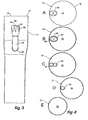
Figures 1. to 4 showing a first embodiment of a stent graft, it will be seen thatstent graft 10 has a tubular body 1 2 of a biocompatible material, which includes a taperedcentral region 14. The tubular body is supported bystents 16. Preferably these stents are self expanding Gianturco zig-zag Z stents but other forms of stents may also be included or used. - In the
tapered region 14, there are at least two fenestrations 1 8 and 20 defined by aresilient nitinol wire 22 around the periphery of the fenestration. - As can be seen in
Figure 2 , there are a pair oftubes proximal end 28 of thestent graft 10 and thesetubes larger tube 30 which opens into thelumen 32 of thestent graft 10. Thelarger tube 30 is connected by stitching 34 to thetubular body 24 and a zig-zag self-expandingstent 36 is deployed around the outside of the larger body to enable or maintain patency once deployed and released within the human or animal body. - Although
Figures 1 and 2 show a pair oftubes -
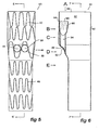
Figure 4 shows various cross-sectional views of the stent graft shown inFigures 1 to 3 . - A top view of the stent graft is shown in
Figure 4A . The stent grafttubular body 12 has the at least twotubes single tube 30 and thesingle tube 30 is joined to thetubular wall 12 at 34 so that thetube 30 is held to one side of the tubular body. -
Figure 4B shows a cross-sectional view at the level B shown inFigure 2 . Thelarger tube 30 is shown in section and thesmaller tubes lumen 32 of the stent grafttubular body 12. -
Figure 4C shows a cross-sectional view at the level C shown inFigure 2 . Thesmaller tubes lumen 32 of the stent grafttubular body 12. -
Figure 4D shows a cross-sectional view at the level D shown inFigure 2 . It can be seen that thetubular body 12 is of lesser diameter because the tubular body is in thetapered portion 14 and only thetube 24 can be seen in cross-section. - Further distally, at the cross-section E as shown in
Figure 4 , the tubular body is substantially circular but of lesser diameter than further up. - The
smaller tubes - Now looking at
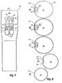
Figures 5 to 8 , showing an alternative embodiment of a stent graft according to the present invention, it will be seen thatstent graft 40 has atubular body 12 which includes a taperedcentral region 44. The tubular body is supported bystents 46. Preferably these stents are self-expanding Gianturco zig-zag Z stents but other forms of stents may also be included or used. - In the
tapered region 14, there are at least twofenestrations resilient nitinol wire 52 around the periphery of the fenestration. - As can be seen in
Figures 6 and7 , there are a pair oftubes fenestrations stent graft 40 and thesetubes larger tube 60 which opens into thelumen 62 of thestent graft 40. Thelarger tube 60 is connected by stitching 64 to thetubular body 44. - As with the first disclosed embodiment, this embodiment could also have more than two
tubes - As can be particularly seen in
Figure 7 thelarger tube 60 has a zig-zag self-expandingstent 66 deployed around the outside of the larger tube to enable or maintain patency once deployed and released within the human or animal body. Thesmaller tubes fenestrations self expanding stents 57 deployed around their outsides to maintain patency of these tubes once the stent graft has been deployed and released within the human or animal body. -
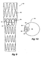
Figure 8 shows various cross-sectional views of the stent graft shown inFigures 5 to 7 . - A top view of the stent graft is shown in
Figure 8A . The stent grafttubular body 42 has the at least twotubes single tube 60 and thesingle tube 60 is joined to thetubular wall 42 at 64 so that thetube 60 is held to one side of the tubular body. -
Figure 8B shows a cross-sectional view at the level B shown inFigure 6 . Thelarger tube 60 is shown in section and thesmaller tubes lumen 62 of the stent grafttubular body 42. -
Figure 8C shows a cross-sectional view at the level C shown inFigure 6 . Thesmaller tubes lumen 62 of the stent grafttubular body 42. -
Figure 8D shows a cross-sectional view at the level D shown inFigure 6 . It can be seen that thetubular body 42 is of lesser diameter because the tubular body is in the taperedportion 44 and part of thetubes - Further distally at the cross-section E as shown in
Figure 8 the tubular body is substantially circular but of lesser diameter than further proximally. -
Figure 9 shows another embodiment of the stent graft according to the present invention. In this embodiment the stent graft has atubular body 80 supported bystents 82. In this embodiment there are at least threefenestrations tubes fenestrations fenestrations - As can be seen in
Figure 10 , the threetubes larger tube 96 within thelumen 98 of thetubular body 80. - Throughout this specification various indications have been given as to the scope of this invention but the invention is not limited to any one of these but may reside in two or more of these combined together. The examples are given for illustration only and not for limitation.
- Throughout this specification and the claims that follow unless the context requires otherwise, the words 'comprise' and 'include' and variations such as 'comprising' and 'including' will be understood to imply the inclusion of a stated integer or group of integers but not the exclusion of any other integer or group of integers.
Claims (10)
- A stent graft (10; 40; 80) including a tubular body (12; 42; 82) of a biocompatible material, at least two fenestrations (18, 20; 48, 50; 84, 86, 88) in the tubular body, the at least two fenestrations being adjacent to each other, a tube (24, 26; 54, 55; 90, 92, 94) extending into the tubular body from each fenestration and the tubes being joined and opering into a single tube of larger diameter (30; 60; 96) within the tubular body.
- A stent graft (10; 40; 80) as claimed in claim 1, wherein the tubes (24, 26; 54, 55; 90, 92, 94) extend towards the proximal end of the stent graft from the fenestrations (18, 20; 48, 50; 84, 86, 88).
- A stent graft (10; 40; 80) as claimed in claim 1 or 2, wherein the tubular body (12; 42; 82) has a tapered portion (14; 44) and the fenestrations (18, 20; 48, 50; 84, 86, 88) are provided in the tapered portion.
- A stent graft (10; 40; 80) as claimed in claim 1, 2 or 3, wherein the single tube of larger diameter (30; 60; 96) is joined to the wall of the tubular body (12; 42; 82) so that it is held to one side of the lumen (32; 62; 98) through the stent graft.
- A stent graft (10; 40; 80) as claimed in any preceding claim, wherein the at least two tubes (24, 26; 54, 55; 90, 92, 94) extend to positions that are adjacent one another laterally around the tubular body (12; 42; 82).
- A stent graft (10; 40; 80) as claimed in any of claims 1 to 4, wherein the at least two tubes (24, 26; 54, 55; 90, 92, 94) extend to positions that are adjacent one another longitudinally along the tubular body (12; 42; 82).
- A stent graft (80) as claimed in any preceding claim, including at least three fenestrations (84, 86, 88) in the tubular body (82) and at least three tubes (90, 92, 94) extend from the fenestrations to the single tube of larger diameter (96).
- A stent graft (10; 40; 80) as claimed in any preceding claim, wherein at least one of the fenestrations (18, 20; 48, 50; 84, 86, 88) includes at least one reinforcing ring of nitinol wire therearound.
- A stent graft (10; 40; 80) as claimed in any preceding claim, wherein the single tube of larger diameter (30; 60; 96) includes an external zig-zag self-expanding stent (36; 66).
- A stent graft (10; 40; 60) as claimed in any preceding claim, wherein each of the at least two tubes (24, 26; 54, 55; 90, 92, 94) include at least one external zig-zag self-expanding stent (57) thereon.
Applications Claiming Priority (2)
| Application Number | Priority Date | Filing Date | Title |
|---|---|---|---|
| US83877606P | 2006-08-18 | 2006-08-18 | |
| PCT/US2007/018410 WO2008021557A1 (en) | 2006-08-18 | 2007-08-20 | Stent graft |
Publications (2)
| Publication Number | Publication Date |
|---|---|
| EP2051663A1 EP2051663A1 (en) | 2009-04-29 |
| EP2051663B1 true EP2051663B1 (en) | 2009-11-18 |
Family
ID=38829659
Family Applications (1)
| Application Number | Title | Priority Date | Filing Date |
|---|---|---|---|
| EP07837090A Active EP2051663B1 (en) | 2006-08-18 | 2007-08-20 | Stent graft |
Country Status (8)
| Country | Link |
|---|---|
| US (1) | US8021419B2 (en) |
| EP (1) | EP2051663B1 (en) |
| JP (1) | JP4979034B2 (en) |
| AT (1) | ATE448754T1 (en) |
| AU (1) | AU2007284362C1 (en) |
| CA (1) | CA2659848C (en) |
| DE (1) | DE602007003384D1 (en) |
| WO (1) | WO2008021557A1 (en) |
Cited By (5)
| Publication number | Priority date | Publication date | Assignee | Title |
|---|---|---|---|---|
| US9592112B2 (en) | 2011-11-16 | 2017-03-14 | Bolton Medical, Inc. | Device and method for aortic branched vessel repair |
| US10390932B2 (en) | 2016-04-05 | 2019-08-27 | Bolton Medical, Inc. | Stent graft with internal tunnels and fenestrations and methods of use |
| US10524893B2 (en) | 2014-09-23 | 2020-01-07 | Bolton Medical, Inc. | Vascular repair devices and methods of use |
| US11395750B2 (en) | 2016-05-25 | 2022-07-26 | Bolton Medical, Inc. | Stent grafts and methods of use for treating aneurysms |
| US11446167B2 (en) | 2011-11-11 | 2022-09-20 | Bolton Medical, Inc. | Universal endovascular grafts |
Families Citing this family (45)
| Publication number | Priority date | Publication date | Assignee | Title |
|---|---|---|---|---|
| US20130274857A1 (en) * | 2000-12-11 | 2013-10-17 | W. L. Gore & Associates, Inc. | Bifurcated side-access intravascular stent graft |
| US7147661B2 (en) | 2001-12-20 | 2006-12-12 | Boston Scientific Santa Rosa Corp. | Radially expandable stent |
| US9597209B2 (en) * | 2005-02-17 | 2017-03-21 | Khoury Medical Devices, Llc | Vascular endograft |
| WO2008021556A1 (en) | 2006-08-18 | 2008-02-21 | William A. Cook Australia Pty. Ltd. | Stent graft extension |
| EP2111190B1 (en) | 2007-01-19 | 2013-10-09 | Medtronic, Inc. | Stented heart valve devices for atrioventricular valve replacement |
| JP5574123B2 (en) | 2008-08-26 | 2014-08-20 | クック メディカル テクノロジーズ エルエルシー | Thoracic aortic stent graft with access region |
| WO2010111583A1 (en) * | 2009-03-26 | 2010-09-30 | Cook Incorporated | Stent graft |
| US8870938B2 (en) | 2009-06-23 | 2014-10-28 | Endospan Ltd. | Vascular prostheses for treating aneurysms |
| WO2011064782A2 (en) | 2009-11-30 | 2011-06-03 | Endospan Ltd. | Multi-component stent-graft system for implantation in a blood vessel with multiple branches |
| CA2788838C (en) | 2010-02-09 | 2017-03-14 | Cook Medical Technologies Llc | Thoracic aorta stent graft |
| AU2010202544B1 (en) | 2010-06-18 | 2010-08-26 | Cook Incorporated | Side branch stent graft |
| US8753386B2 (en) * | 2010-11-15 | 2014-06-17 | W. L. Gore & Associates, Inc. | Stent-graft having facing side branch portals |
| US9566149B2 (en) * | 2010-11-16 | 2017-02-14 | W. L. Gore & Associates, Inc. | Devices and methods for in situ fenestration of a stent-graft at the site of a branch vessel |
| US9675487B2 (en) | 2010-11-17 | 2017-06-13 | Cook Medical Technologies Llc | Prosthesis deployment system for vascular repair |
| US8657866B2 (en) | 2010-12-22 | 2014-02-25 | Cook Medical Technologies Llc | Emergency vascular repair prosthesis deployment system |
| US9526638B2 (en) | 2011-02-03 | 2016-12-27 | Endospan Ltd. | Implantable medical devices constructed of shape memory material |
| WO2013005207A1 (en) | 2011-07-07 | 2013-01-10 | Endospan Ltd. | Stent fixation with reduced plastic deformation |
| US9314328B2 (en) * | 2011-08-16 | 2016-04-19 | W. L. Gore & Associates, Inc. | Branched stent graft device and deployment |
| EP2747705B1 (en) | 2011-08-22 | 2017-06-28 | Cook Medical Technologies LLC | Emergency vessel repair prosthesis deployment system |
| US9839510B2 (en) | 2011-08-28 | 2017-12-12 | Endospan Ltd. | Stent-grafts with post-deployment variable radial displacement |
| WO2013065040A1 (en) | 2011-10-30 | 2013-05-10 | Endospan Ltd. | Triple-collar stent-graft |
| WO2013084235A2 (en) | 2011-12-04 | 2013-06-13 | Endospan Ltd. | Branched stent-graft system |
| DE102012103987A1 (en) * | 2012-05-07 | 2013-11-07 | Jotec Gmbh | Intraluminal vascular prosthesis with in situ fenestration |
| DE102012103985A1 (en) * | 2012-05-07 | 2013-11-07 | Jotec Gmbh | Intraluminal vascular prosthesis with in situ fenestration |
| WO2013171730A1 (en) | 2012-05-15 | 2013-11-21 | Endospan Ltd. | Stent-graft with fixation elements that are radially confined for delivery |
| EP2906144B1 (en) * | 2012-10-10 | 2017-08-02 | TriVascular, Inc. | Endovascular graft for aneurysms involving major branch vessels |
| WO2014108895A2 (en) | 2013-01-08 | 2014-07-17 | Endospan Ltd. | Minimization of stent-graft migration during implantation |
| US9668892B2 (en) | 2013-03-11 | 2017-06-06 | Endospan Ltd. | Multi-component stent-graft system for aortic dissections |
| US10603197B2 (en) | 2013-11-19 | 2020-03-31 | Endospan Ltd. | Stent system with radial-expansion locking |
| US20170007392A1 (en) * | 2014-01-23 | 2017-01-12 | Biokyra Pesquisa E Desenvolvimento Ltda. | Endoprosthesis for endovascular treatment of thoracic-abdominal aortic aneurysms or dissections and endoprosthesis for endovascular treatment of abdominal aortic aneurysms or dissections which compromise the iliac arteries |
| CN104116577B (en) * | 2014-06-27 | 2017-07-14 | 先健科技(深圳)有限公司 | Branch type overlay film frame |
| US9956101B2 (en) | 2014-12-04 | 2018-05-01 | Trivascular, Inc. | Internal iliac preservation devices and methods |
| EP3068339B1 (en) | 2014-12-18 | 2017-11-01 | Endospan Ltd. | Endovascular stent-graft with fatigue-resistant lateral tube |
| ES2921535T3 (en) | 2015-06-18 | 2022-08-29 | Ascyrus Medical Llc | Branch aortic graft |
| DE102015123000A1 (en) * | 2015-12-30 | 2017-07-06 | Jotec Gmbh | Self-expanding vascular prosthesis |
| DE102016102008A1 (en) * | 2016-02-04 | 2017-08-10 | Jotec Gmbh | Vascular prosthesis with side branches |
| US10537419B2 (en) | 2016-10-27 | 2020-01-21 | Cook Medical Technologies Llc | Prosthesis with branched portion |
| US10660770B2 (en) | 2017-07-18 | 2020-05-26 | Cook Medical Technologies Llc | Method of making an internal bidirectional branch |
| CN109419566B (en) | 2017-08-28 | 2020-09-29 | 先健科技(深圳)有限公司 | Covered stent |
| CN209474879U (en) * | 2017-11-24 | 2019-10-11 | 杭州唯强医疗科技有限公司 | Improve the vascular shunt frame and intravascular stent of adherence quality |
| CN209678753U (en) | 2017-11-24 | 2019-11-26 | 杭州唯强医疗科技有限公司 | Multilumen Stent Graft |
| WO2020125226A1 (en) * | 2018-12-18 | 2020-06-25 | 深圳市先健畅通医疗有限公司 | Lumen stent and implant |
| CN111407476B (en) * | 2018-12-18 | 2021-07-20 | 深圳市先健畅通医疗有限公司 | Lumen stent |
| CN111407475B (en) * | 2018-12-18 | 2021-07-20 | 深圳市先健畅通医疗有限公司 | Lumen stent |
| CN110448393B (en) * | 2018-12-18 | 2021-04-13 | 深圳市先健畅通医疗有限公司 | Lumen stent |
Family Cites Families (7)
| Publication number | Priority date | Publication date | Assignee | Title |
|---|---|---|---|---|
| US6187033B1 (en) * | 1997-09-04 | 2001-02-13 | Meadox Medicals, Inc. | Aortic arch prosthetic graft |
| US6814752B1 (en) | 2000-03-03 | 2004-11-09 | Endovascular Technologies, Inc. | Modular grafting system and method |
| JP4208075B2 (en) * | 2002-03-25 | 2009-01-14 | クック インコーポレイティド | Bifurcated / branched vascular prosthesis |
| EP1608293B1 (en) * | 2003-04-03 | 2015-06-03 | Cook Medical Technologies LLC | Deployment system for a branched stent graft |
| ATE392865T1 (en) * | 2003-10-10 | 2008-05-15 | Cook William A Australia | STENT IMPLANTS WITH WINDOWS |
| US7828837B2 (en) * | 2005-02-17 | 2010-11-09 | Khoury Medical Devices, LLC. | Vascular endograft |
| WO2006113501A1 (en) * | 2005-04-13 | 2006-10-26 | The Cleveland Clinic Foundation | Endoluminal prosthesis |
-
2007
- 2007-08-20 CA CA2659848A patent/CA2659848C/en active Active
- 2007-08-20 DE DE602007003384T patent/DE602007003384D1/en active Active
- 2007-08-20 WO PCT/US2007/018410 patent/WO2008021557A1/en not_active Ceased
- 2007-08-20 EP EP07837090A patent/EP2051663B1/en active Active
- 2007-08-20 JP JP2009524706A patent/JP4979034B2/en active Active
- 2007-08-20 AU AU2007284362A patent/AU2007284362C1/en active Active
- 2007-08-20 AT AT07837090T patent/ATE448754T1/en not_active IP Right Cessation
- 2007-08-20 US US12/377,438 patent/US8021419B2/en active Active
Cited By (10)
| Publication number | Priority date | Publication date | Assignee | Title |
|---|---|---|---|---|
| US11446167B2 (en) | 2011-11-11 | 2022-09-20 | Bolton Medical, Inc. | Universal endovascular grafts |
| US9592112B2 (en) | 2011-11-16 | 2017-03-14 | Bolton Medical, Inc. | Device and method for aortic branched vessel repair |
| US10390930B2 (en) | 2011-11-16 | 2019-08-27 | Bolton Medical, Inc. | Method for aortic branched vessel repair |
| US11547549B2 (en) | 2011-11-16 | 2023-01-10 | Bolton Medical, Inc. | Aortic graft assembly |
| US10524893B2 (en) | 2014-09-23 | 2020-01-07 | Bolton Medical, Inc. | Vascular repair devices and methods of use |
| US11065100B2 (en) | 2014-09-23 | 2021-07-20 | Bolton Medical, Inc. | Vascular repair devices and methods of use |
| US10390932B2 (en) | 2016-04-05 | 2019-08-27 | Bolton Medical, Inc. | Stent graft with internal tunnels and fenestrations and methods of use |
| US11154392B2 (en) | 2016-04-05 | 2021-10-26 | Bolton Medical, Inc. | Stent graft with internal tunnels and fenestrations and methods of use |
| US12127930B2 (en) | 2016-04-05 | 2024-10-29 | Bolton Medical, Inc. | Stent graft with internal tunnels and fenestrations and methods of use |
| US11395750B2 (en) | 2016-05-25 | 2022-07-26 | Bolton Medical, Inc. | Stent grafts and methods of use for treating aneurysms |
Also Published As
| Publication number | Publication date |
|---|---|
| US8021419B2 (en) | 2011-09-20 |
| US20090319022A1 (en) | 2009-12-24 |
| WO2008021557A1 (en) | 2008-02-21 |
| EP2051663A1 (en) | 2009-04-29 |
| AU2007284362B2 (en) | 2012-03-22 |
| JP4979034B2 (en) | 2012-07-18 |
| ATE448754T1 (en) | 2009-12-15 |
| CA2659848A1 (en) | 2008-02-21 |
| DE602007003384D1 (en) | 2009-12-31 |
| JP2010501208A (en) | 2010-01-21 |
| AU2007284362A1 (en) | 2008-02-21 |
| CA2659848C (en) | 2015-10-06 |
| AU2007284362C1 (en) | 2012-08-23 |
Similar Documents
| Publication | Publication Date | Title |
|---|---|---|
| EP2051663B1 (en) | Stent graft | |
| US10143576B2 (en) | Twin bifurcated stent graft | |
| US8992593B2 (en) | Apparatus and methods for deployment of a modular stent-graft system | |
| JP5621093B2 (en) | Chest stent graft | |
| US9005268B2 (en) | Thoracic stent graft | |
| EP2491892B1 (en) | Stent graft with valve arrangement and introducer assembly therefor | |
| AU2010306961B2 (en) | Paraplegia prevention stent graft | |
| US9211183B2 (en) | Thoracic stent graft with guide arrangement | |
| EP4674379A1 (en) | Branch artery reconstruction assisting device and s-c branch-first aorta reconstruction system | |
| US11219518B2 (en) | Oblique seam for reduced stent graft packing density in delivery system | |
| AU2014200561B2 (en) | Prosthesis | |
| AU2011250799B2 (en) | Bifurcated stent graft with valve | |
| AU2011250798A1 (en) | Bifurcated-bifurcated stent graft |
Legal Events
| Date | Code | Title | Description |
|---|---|---|---|
| PUAI | Public reference made under article 153(3) epc to a published international application that has entered the european phase |
Free format text: ORIGINAL CODE: 0009012 |
|
| 17P | Request for examination filed |
Effective date: 20090216 |
|
| AK | Designated contracting states |
Kind code of ref document: A1 Designated state(s): AT BE BG CH CY CZ DE DK EE ES FI FR GB GR HU IE IS IT LI LT LU LV MC MT NL PL PT RO SE SI SK TR |
|
| AX | Request for extension of the european patent |
Extension state: AL BA HR MK RS |
|
| GRAP | Despatch of communication of intention to grant a patent |
Free format text: ORIGINAL CODE: EPIDOSNIGR1 |
|
| GRAS | Grant fee paid |
Free format text: ORIGINAL CODE: EPIDOSNIGR3 |
|
| GRAA | (expected) grant |
Free format text: ORIGINAL CODE: 0009210 |
|
| AK | Designated contracting states |
Kind code of ref document: B1 Designated state(s): AT BE BG CH CY CZ DE DK EE ES FI FR GB GR HU IE IS IT LI LT LU LV MC MT NL PL PT RO SE SI SK TR |
|
| REG | Reference to a national code |
Ref country code: GB Ref legal event code: FG4D |
|
| REG | Reference to a national code |
Ref country code: CH Ref legal event code: EP |
|
| REG | Reference to a national code |
Ref country code: IE Ref legal event code: FG4D |
|
| REF | Corresponds to: |
Ref document number: 602007003384 Country of ref document: DE Date of ref document: 20091231 Kind code of ref document: P |
|
| REG | Reference to a national code |
Ref country code: NL Ref legal event code: VDEP Effective date: 20091118 |
|
| LTIE | Lt: invalidation of european patent or patent extension |
Effective date: 20091118 |
|
| PG25 | Lapsed in a contracting state [announced via postgrant information from national office to epo] |
Ref country code: PT Free format text: LAPSE BECAUSE OF FAILURE TO SUBMIT A TRANSLATION OF THE DESCRIPTION OR TO PAY THE FEE WITHIN THE PRESCRIBED TIME-LIMIT Effective date: 20100318 Ref country code: ES Free format text: LAPSE BECAUSE OF FAILURE TO SUBMIT A TRANSLATION OF THE DESCRIPTION OR TO PAY THE FEE WITHIN THE PRESCRIBED TIME-LIMIT Effective date: 20100228 Ref country code: SE Free format text: LAPSE BECAUSE OF FAILURE TO SUBMIT A TRANSLATION OF THE DESCRIPTION OR TO PAY THE FEE WITHIN THE PRESCRIBED TIME-LIMIT Effective date: 20091118 Ref country code: IS Free format text: LAPSE BECAUSE OF FAILURE TO SUBMIT A TRANSLATION OF THE DESCRIPTION OR TO PAY THE FEE WITHIN THE PRESCRIBED TIME-LIMIT Effective date: 20100318 Ref country code: LT Free format text: LAPSE BECAUSE OF FAILURE TO SUBMIT A TRANSLATION OF THE DESCRIPTION OR TO PAY THE FEE WITHIN THE PRESCRIBED TIME-LIMIT Effective date: 20091118 Ref country code: FI Free format text: LAPSE BECAUSE OF FAILURE TO SUBMIT A TRANSLATION OF THE DESCRIPTION OR TO PAY THE FEE WITHIN THE PRESCRIBED TIME-LIMIT Effective date: 20091118 |
|
| PG25 | Lapsed in a contracting state [announced via postgrant information from national office to epo] |
Ref country code: CY Free format text: LAPSE BECAUSE OF FAILURE TO SUBMIT A TRANSLATION OF THE DESCRIPTION OR TO PAY THE FEE WITHIN THE PRESCRIBED TIME-LIMIT Effective date: 20091118 Ref country code: PL Free format text: LAPSE BECAUSE OF FAILURE TO SUBMIT A TRANSLATION OF THE DESCRIPTION OR TO PAY THE FEE WITHIN THE PRESCRIBED TIME-LIMIT Effective date: 20091118 Ref country code: SI Free format text: LAPSE BECAUSE OF FAILURE TO SUBMIT A TRANSLATION OF THE DESCRIPTION OR TO PAY THE FEE WITHIN THE PRESCRIBED TIME-LIMIT Effective date: 20091118 Ref country code: LV Free format text: LAPSE BECAUSE OF FAILURE TO SUBMIT A TRANSLATION OF THE DESCRIPTION OR TO PAY THE FEE WITHIN THE PRESCRIBED TIME-LIMIT Effective date: 20091118 |
|
| PG25 | Lapsed in a contracting state [announced via postgrant information from national office to epo] |
Ref country code: BE Free format text: LAPSE BECAUSE OF FAILURE TO SUBMIT A TRANSLATION OF THE DESCRIPTION OR TO PAY THE FEE WITHIN THE PRESCRIBED TIME-LIMIT Effective date: 20091118 Ref country code: AT Free format text: LAPSE BECAUSE OF FAILURE TO SUBMIT A TRANSLATION OF THE DESCRIPTION OR TO PAY THE FEE WITHIN THE PRESCRIBED TIME-LIMIT Effective date: 20091118 |
|
| PG25 | Lapsed in a contracting state [announced via postgrant information from national office to epo] |
Ref country code: DK Free format text: LAPSE BECAUSE OF FAILURE TO SUBMIT A TRANSLATION OF THE DESCRIPTION OR TO PAY THE FEE WITHIN THE PRESCRIBED TIME-LIMIT Effective date: 20091118 Ref country code: EE Free format text: LAPSE BECAUSE OF FAILURE TO SUBMIT A TRANSLATION OF THE DESCRIPTION OR TO PAY THE FEE WITHIN THE PRESCRIBED TIME-LIMIT Effective date: 20091118 Ref country code: BG Free format text: LAPSE BECAUSE OF FAILURE TO SUBMIT A TRANSLATION OF THE DESCRIPTION OR TO PAY THE FEE WITHIN THE PRESCRIBED TIME-LIMIT Effective date: 20100218 Ref country code: NL Free format text: LAPSE BECAUSE OF FAILURE TO SUBMIT A TRANSLATION OF THE DESCRIPTION OR TO PAY THE FEE WITHIN THE PRESCRIBED TIME-LIMIT Effective date: 20091118 Ref country code: RO Free format text: LAPSE BECAUSE OF FAILURE TO SUBMIT A TRANSLATION OF THE DESCRIPTION OR TO PAY THE FEE WITHIN THE PRESCRIBED TIME-LIMIT Effective date: 20091118 |
|
| PG25 | Lapsed in a contracting state [announced via postgrant information from national office to epo] |
Ref country code: CZ Free format text: LAPSE BECAUSE OF FAILURE TO SUBMIT A TRANSLATION OF THE DESCRIPTION OR TO PAY THE FEE WITHIN THE PRESCRIBED TIME-LIMIT Effective date: 20091118 Ref country code: SK Free format text: LAPSE BECAUSE OF FAILURE TO SUBMIT A TRANSLATION OF THE DESCRIPTION OR TO PAY THE FEE WITHIN THE PRESCRIBED TIME-LIMIT Effective date: 20091118 |
|
| PLBE | No opposition filed within time limit |
Free format text: ORIGINAL CODE: 0009261 |
|
| STAA | Information on the status of an ep patent application or granted ep patent |
Free format text: STATUS: NO OPPOSITION FILED WITHIN TIME LIMIT |
|
| 26N | No opposition filed |
Effective date: 20100819 |
|
| PG25 | Lapsed in a contracting state [announced via postgrant information from national office to epo] |
Ref country code: GR Free format text: LAPSE BECAUSE OF FAILURE TO SUBMIT A TRANSLATION OF THE DESCRIPTION OR TO PAY THE FEE WITHIN THE PRESCRIBED TIME-LIMIT Effective date: 20100219 |
|
| PG25 | Lapsed in a contracting state [announced via postgrant information from national office to epo] |
Ref country code: MC Free format text: LAPSE BECAUSE OF NON-PAYMENT OF DUE FEES Effective date: 20100831 Ref country code: IT Free format text: LAPSE BECAUSE OF FAILURE TO SUBMIT A TRANSLATION OF THE DESCRIPTION OR TO PAY THE FEE WITHIN THE PRESCRIBED TIME-LIMIT Effective date: 20091118 |
|
| REG | Reference to a national code |
Ref country code: FR Ref legal event code: ST Effective date: 20110502 |
|
| PG25 | Lapsed in a contracting state [announced via postgrant information from national office to epo] |
Ref country code: FR Free format text: LAPSE BECAUSE OF NON-PAYMENT OF DUE FEES Effective date: 20100831 |
|
| REG | Reference to a national code |
Ref country code: GB Ref legal event code: 732E Free format text: REGISTERED BETWEEN 20111117 AND 20111123 |
|
| PG25 | Lapsed in a contracting state [announced via postgrant information from national office to epo] |
Ref country code: MT Free format text: LAPSE BECAUSE OF FAILURE TO SUBMIT A TRANSLATION OF THE DESCRIPTION OR TO PAY THE FEE WITHIN THE PRESCRIBED TIME-LIMIT Effective date: 20091118 |
|
| REG | Reference to a national code |
Ref country code: CH Ref legal event code: PL |
|
| PG25 | Lapsed in a contracting state [announced via postgrant information from national office to epo] |
Ref country code: LI Free format text: LAPSE BECAUSE OF NON-PAYMENT OF DUE FEES Effective date: 20110831 Ref country code: CH Free format text: LAPSE BECAUSE OF NON-PAYMENT OF DUE FEES Effective date: 20110831 |
|
| PG25 | Lapsed in a contracting state [announced via postgrant information from national office to epo] |
Ref country code: LU Free format text: LAPSE BECAUSE OF NON-PAYMENT OF DUE FEES Effective date: 20100820 Ref country code: HU Free format text: LAPSE BECAUSE OF FAILURE TO SUBMIT A TRANSLATION OF THE DESCRIPTION OR TO PAY THE FEE WITHIN THE PRESCRIBED TIME-LIMIT Effective date: 20100519 |
|
| PG25 | Lapsed in a contracting state [announced via postgrant information from national office to epo] |
Ref country code: TR Free format text: LAPSE BECAUSE OF FAILURE TO SUBMIT A TRANSLATION OF THE DESCRIPTION OR TO PAY THE FEE WITHIN THE PRESCRIBED TIME-LIMIT Effective date: 20091118 |
|
| P01 | Opt-out of the competence of the unified patent court (upc) registered |
Effective date: 20230602 |
|
| REG | Reference to a national code |
Ref country code: GB Ref legal event code: 732E Free format text: REGISTERED BETWEEN 20240815 AND 20240821 |
|
| REG | Reference to a national code |
Ref country code: DE Ref legal event code: R081 Ref document number: 602007003384 Country of ref document: DE Owner name: COOK MEDICAL TECHNOLOGIES, LLC, BLOOMINGTON, US Free format text: FORMER OWNERS: COOK INC., BLOOMINGTON, IND., US; WILLIAM A. COOK AUSTRALIA PTY. LTD., BRISBANE, QUEENSLAND, AU |
|
| PGFP | Annual fee paid to national office [announced via postgrant information from national office to epo] |
Ref country code: DE Payment date: 20250827 Year of fee payment: 19 |
|
| PGFP | Annual fee paid to national office [announced via postgrant information from national office to epo] |
Ref country code: GB Payment date: 20250826 Year of fee payment: 19 |
|
| PGFP | Annual fee paid to national office [announced via postgrant information from national office to epo] |
Ref country code: IE Payment date: 20250819 Year of fee payment: 19 |