JP4977017B2 - Snare injection device - Google Patents
Snare injection device Download PDFInfo
- Publication number
- JP4977017B2 JP4977017B2 JP2007515282A JP2007515282A JP4977017B2 JP 4977017 B2 JP4977017 B2 JP 4977017B2 JP 2007515282 A JP2007515282 A JP 2007515282A JP 2007515282 A JP2007515282 A JP 2007515282A JP 4977017 B2 JP4977017 B2 JP 4977017B2
- Authority
- JP
- Japan
- Prior art keywords
- needle
- snare
- channel
- tube
- target tissue
- Prior art date
- Legal status (The legal status is an assumption and is not a legal conclusion. Google has not performed a legal analysis and makes no representation as to the accuracy of the status listed.)
- Active
Links
- 238000002347 injection Methods 0.000 title claims description 20
- 239000007924 injection Substances 0.000 title claims description 20
- 238000000034 method Methods 0.000 claims description 22
- 238000001802 infusion Methods 0.000 claims description 10
- 125000006850 spacer group Chemical group 0.000 claims description 10
- 239000012528 membrane Substances 0.000 claims description 9
- 239000004033 plastic Substances 0.000 claims description 9
- 229920003023 plastic Polymers 0.000 claims description 9
- 238000007665 sagging Methods 0.000 claims description 4
- 230000000149 penetrating effect Effects 0.000 claims 2
- 239000002985 plastic film Substances 0.000 claims 2
- 229920006255 plastic film Polymers 0.000 claims 2
- 238000003780 insertion Methods 0.000 claims 1
- 230000037431 insertion Effects 0.000 claims 1
- 230000002093 peripheral effect Effects 0.000 claims 1
- 210000001519 tissue Anatomy 0.000 description 15
- 239000012530 fluid Substances 0.000 description 8
- 230000009977 dual effect Effects 0.000 description 7
- 208000037062 Polyps Diseases 0.000 description 6
- 239000000463 material Substances 0.000 description 5
- -1 for example Substances 0.000 description 4
- 230000007246 mechanism Effects 0.000 description 4
- 230000006378 damage Effects 0.000 description 3
- 230000006872 improvement Effects 0.000 description 3
- 210000003205 muscle Anatomy 0.000 description 3
- 230000007704 transition Effects 0.000 description 3
- 239000004698 Polyethylene Substances 0.000 description 2
- 238000002679 ablation Methods 0.000 description 2
- 230000006978 adaptation Effects 0.000 description 2
- 230000008901 benefit Effects 0.000 description 2
- 230000000740 bleeding effect Effects 0.000 description 2
- 238000012326 endoscopic mucosal resection Methods 0.000 description 2
- 238000012143 endoscopic resection Methods 0.000 description 2
- 230000002496 gastric effect Effects 0.000 description 2
- 238000012986 modification Methods 0.000 description 2
- 230000004048 modification Effects 0.000 description 2
- 229920000573 polyethylene Polymers 0.000 description 2
- 229920001343 polytetrafluoroethylene Polymers 0.000 description 2
- 239000004810 polytetrafluoroethylene Substances 0.000 description 2
- 238000002271 resection Methods 0.000 description 2
- FAPWRFPIFSIZLT-UHFFFAOYSA-M Sodium chloride Chemical compound [Na+].[Cl-] FAPWRFPIFSIZLT-UHFFFAOYSA-M 0.000 description 1
- 230000002159 abnormal effect Effects 0.000 description 1
- 238000010521 absorption reaction Methods 0.000 description 1
- 239000000853 adhesive Substances 0.000 description 1
- 230000001070 adhesive effect Effects 0.000 description 1
- 210000004204 blood vessel Anatomy 0.000 description 1
- 239000011248 coating agent Substances 0.000 description 1
- 238000000576 coating method Methods 0.000 description 1
- 230000008878 coupling Effects 0.000 description 1
- 238000010168 coupling process Methods 0.000 description 1
- 238000005859 coupling reaction Methods 0.000 description 1
- 201000010099 disease Diseases 0.000 description 1
- 208000037265 diseases, disorders, signs and symptoms Diseases 0.000 description 1
- 239000003000 extruded plastic Substances 0.000 description 1
- 230000002349 favourable effect Effects 0.000 description 1
- 210000003811 finger Anatomy 0.000 description 1
- 210000001035 gastrointestinal tract Anatomy 0.000 description 1
- 230000002439 hemostatic effect Effects 0.000 description 1
- 230000003902 lesion Effects 0.000 description 1
- 239000002184 metal Substances 0.000 description 1
- 238000012544 monitoring process Methods 0.000 description 1
- 210000004877 mucosa Anatomy 0.000 description 1
- 239000012811 non-conductive material Substances 0.000 description 1
- 230000019612 pigmentation Effects 0.000 description 1
- 238000000926 separation method Methods 0.000 description 1
- 239000000243 solution Substances 0.000 description 1
- 210000004876 tela submucosa Anatomy 0.000 description 1
- 230000003685 thermal hair damage Effects 0.000 description 1
- 210000003813 thumb Anatomy 0.000 description 1
- 230000000007 visual effect Effects 0.000 description 1
Images


Classifications
-
- A—HUMAN NECESSITIES
- A61—MEDICAL OR VETERINARY SCIENCE; HYGIENE
- A61B—DIAGNOSIS; SURGERY; IDENTIFICATION
- A61B17/00—Surgical instruments, devices or methods, e.g. tourniquets
- A61B17/32—Surgical cutting instruments
- A61B17/3205—Excision instruments
- A61B17/32056—Surgical snare instruments
-
- A—HUMAN NECESSITIES
- A61—MEDICAL OR VETERINARY SCIENCE; HYGIENE
- A61B—DIAGNOSIS; SURGERY; IDENTIFICATION
- A61B17/00—Surgical instruments, devices or methods, e.g. tourniquets
- A61B17/34—Trocars; Puncturing needles
- A61B17/3478—Endoscopic needles, e.g. for infusion
-
- A—HUMAN NECESSITIES
- A61—MEDICAL OR VETERINARY SCIENCE; HYGIENE
- A61B—DIAGNOSIS; SURGERY; IDENTIFICATION
- A61B17/00—Surgical instruments, devices or methods, e.g. tourniquets
- A61B17/02—Surgical instruments, devices or methods, e.g. tourniquets for holding wounds open; Tractors
- A61B17/0218—Surgical instruments, devices or methods, e.g. tourniquets for holding wounds open; Tractors for minimally invasive surgery
-
- A—HUMAN NECESSITIES
- A61—MEDICAL OR VETERINARY SCIENCE; HYGIENE
- A61B—DIAGNOSIS; SURGERY; IDENTIFICATION
- A61B17/00—Surgical instruments, devices or methods, e.g. tourniquets
- A61B17/00234—Surgical instruments, devices or methods, e.g. tourniquets for minimally invasive surgery
- A61B2017/00238—Type of minimally invasive operation
- A61B2017/00269—Type of minimally invasive operation endoscopic mucosal resection EMR
-
- A—HUMAN NECESSITIES
- A61—MEDICAL OR VETERINARY SCIENCE; HYGIENE
- A61B—DIAGNOSIS; SURGERY; IDENTIFICATION
- A61B90/00—Instruments, implements or accessories specially adapted for surgery or diagnosis and not covered by any of the groups A61B1/00 - A61B50/00, e.g. for luxation treatment or for protecting wound edges
- A61B90/08—Accessories or related features not otherwise provided for
- A61B2090/0801—Prevention of accidental cutting or pricking
- A61B2090/08021—Prevention of accidental cutting or pricking of the patient or his organs
Description
(関連出願への相互参照)
仮出願でない本出願は、2004年5月25日に出願された「スネア注入デバイス」と題する米国仮特許出願第60/574,073号の利益を主張し、この出願は、その全体が本明細書によって参考として援用される。
(Cross-reference to related applications)
This non-provisional application claims the benefit of US Provisional Patent Application No. 60 / 574,073 entitled “Snare Infusion Device” filed May 25, 2004, which is hereby incorporated by reference in its entirety. Incorporated by reference.
(発明の分野)
本発明は、内視鏡医療デバイス、そしてより特定すれば、内視鏡切除手順を実施するためのスネア注入デバイスに関する。
(Field of Invention)
The present invention relates to an endoscopic medical device, and more particularly to a snare infusion device for performing an endoscopic resection procedure.
(発明の背景)
内視鏡は当該技術分野で周知であり、そして一般に多くの医療手順のために用いられている。1つのこのような手順は、ヒト被験体の胃腸粘膜壁から、ポリープ、病変またはその他のタイプの標的とされた組織を除去することである。
(Background of the Invention)
Endoscopes are well known in the art and are commonly used for many medical procedures. One such procedure is to remove polyps, lesions or other types of targeted tissue from the gastrointestinal mucosal wall of a human subject.
従来のポリープ切除の除去技法にともなういくつかの欠点がある。種々の焼灼デバイスが、ポリープを除去するために開発されている。しかし、これらのデバイスは、ときどき、胃腸壁に重篤な熱損傷を引き起こし、標的とされた組織全体を除去しないか、または血管を完全に焼灼せず、これは、過度の出血に至る。ポリープを取り囲み、そして除去するように設計されたスネアデバイスは、標的とされたすべての組織を捕獲しないかも知れない。さらに、医師は、標的とされた組織をこのスネアで固定することで困難を経験し得る。3つの層の壁、すなわち、粘膜、粘膜下組織、および筋層から必要な最小の組織のみをつかまえることもまた重要である。より詳細には、合併症を避けるために、筋層組織は、このタイプの手順においては避けられるべきである。これらおよびその他の問題を解決する努力において、用いられる1つの技法は、例えば、生理食塩水溶液を組織に注入して、組織をより好ましい位置に持ち上げることを含む、粘膜下リフトポリープ切除である。この技法は、完全な切除を改善する。注入された流体の分離はまた、焼灼または熱損傷から外側筋肉を隔離する。 There are several disadvantages associated with conventional polypectomy removal techniques. Various ablation devices have been developed to remove polyps. However, these devices sometimes cause severe thermal damage to the gastrointestinal wall and do not remove the entire targeted tissue or completely cauterize the blood vessels, leading to excessive bleeding. A snare device designed to surround and remove a polyp may not capture all targeted tissue. In addition, physicians can experience difficulties with fixing the targeted tissue with this snare. It is also important to capture only the minimum tissue required from the three layers of walls, the mucosa, submucosa, and muscle layers. More particularly, muscle tissue should be avoided in this type of procedure to avoid complications. In an effort to solve these and other problems, one technique used is submucosal lift polyp excision, including, for example, injecting saline solution into the tissue and lifting the tissue to a more favorable position. This technique improves complete ablation. The separation of the injected fluid also isolates the outer muscle from cauterization or heat damage.
種々のその他の手順は、ニードルおよびスネアを必要とし、上記部位を洗浄するためのニードルの使用、疾患または異常組織を強調する目的のため、切除後監視目的のために入墨媒体の注入のために色素を付与すること、およびポリープ切除後出血のための止血薬注入治療を含む。スネアおよびニードルを必要とするこれらおよびその他の手順では、医師は、2つの別個の補助器具を用い、そして器具チャネルの内外にそれらを一度に供給しなければならず、これは全体の手順時間を増加する。従って、当該技術分野では、先行技術設計に対する改良を提供するスネア注入のための必要性が存在する。 Various other procedures require needles and snares, use of needles to clean the site, for the purpose of highlighting disease or abnormal tissue, for the injection of tattoo media for post-resection monitoring purposes Includes pigmentation and hemostatic infusion treatment for post-polypectomy bleeding. In these and other procedures that require a snare and needle, the physician must use two separate aids and feed them into and out of the instrument channel at once, which reduces the overall procedure time. To increase. Accordingly, there is a need in the art for snare injection that provides an improvement over prior art designs.
本発明は、各々が二重チャネル管腔の1つのチャネル中に別個に経路をとるスネアおよびニードルを含むデバイスである。このニードルは、上記手順の間に、手順前注入および手順後注入、および手順の間の組織の持ち上げを含むいくつかの機能を実施し得る。本発明はまた、スネアの除去なくして胃腸管壁による持ち上げ流体の吸収に起因して必要であり得る即座の繰り返し注入を可能にする。 The present invention is a device that includes a snare and a needle each routed separately into one channel of a dual channel lumen. The needle may perform several functions during the procedure, including pre-procedural and post-procedural injections, and tissue lifting during the procedure. The present invention also allows for immediate repeated infusions that may be necessary due to the absorption of lifting fluid by the gastrointestinal tract wall without removal of the snare.
本発明は、先行技術ニードルデバイスに対する多くのその他の改良を提供し、ニードル制限機構、種々の内視鏡形態における一致した1:1のハンドル/ニードル軸移動、および穿孔防止特徴を含む。特定の先行技術設計では、ニードルは、デバイスの側壁を穿孔することによるか、または患者に害を引き起こすように所望の長さを超えて展開することにより患者を損傷し得る。従って、本発明は、患者安全性および医師のための使用の容易さにおける改良を提供する。 The present invention provides many other improvements over prior art needle devices, including a needle limiting mechanism, consistent 1: 1 handle / needle axis movement in various endoscope configurations, and anti-piercing features. In certain prior art designs, the needle may damage the patient by piercing the side wall of the device or by deploying beyond a desired length to cause harm to the patient. Thus, the present invention provides improvements in patient safety and ease of use for physicians.
(発明の要旨)
本発明のいくつかの例示の実施形態では、内視鏡ポリープ切除手順を実施するためのスネア注入デバイスが開示される。このデバイスの使用は、ポリープ除去に制限されず、内視鏡粘膜切除(EMR)、接着性血餅除去、または切除もしくは/または注入を必要とするその他の目的のような、その他の手順とともに用いられ得ることは当業者に明らかである。
(Summary of the Invention)
In some exemplary embodiments of the invention, a snare injection device for performing an endoscopic polypectomy procedure is disclosed. The use of this device is not limited to polyp removal and is used in conjunction with other procedures such as endoscopic mucosal resection (EMR), adhesive clot removal, or other purposes that require resection or / or injection. It will be apparent to those skilled in the art that this can be done.
本発明の実施形態では、デバイスは、第1および第2のチャネルを有する二重管腔、流体送達システム、およびスネアシステムを含む。この流体送達システムは、中空のベース、このベースおよび上記第1のチャネルを通って挿入されるアクチュエーター、アクシュエーターチューブ近位端に固定された中空のノブ、およびアクチュエーター遠位端に固定されたニードルを含む。このスネアシステムは、ベースに連結された本体、この本体に対して取り付けられ、かつそれに対して移動可能であるハンドル、上記第2のチャネルを通って実質的に延びるハンドルに固定される近位端を有するケーブル、およびケーブル遠位端に固定されるスネアを含む。 In an embodiment of the invention, the device includes a dual lumen having first and second channels, a fluid delivery system, and a snare system. The fluid delivery system includes a hollow base, an actuator inserted through the base and the first channel, a hollow knob secured to the proximal end of the actuator tube, and a needle secured to the distal end of the actuator. including. The snare system includes a body coupled to a base, a handle attached to and movable relative to the body, a proximal end secured to a handle that extends substantially through the second channel. And a snare secured to the distal end of the cable.
本発明のさらなる特徴および利点は、添付の図面を参照してなされる以下の詳細な説明から明らかになる。 Further features and advantages of the present invention will become apparent from the following detailed description, taken in conjunction with the accompanying drawings.
以下の発明の詳細な説明は、本発明の好ましい実施形態を単に説明しているに過ぎず、そして請求項の範囲をいかなる方法においても制限することは意図されない。実際、請求項によって記載さるような本発明は、好ましい実施形態より広く、そしてそれによって制限されず、そして請求項にある用語は、それらの完全に通常の意味を有している。 The following detailed description of the invention merely illustrates the preferred embodiments of the invention and is not intended to limit the scope of the claims in any way. Indeed, the invention as described by the claims is broader than the preferred embodiments and not limited thereby, and the terms in the claims have their full ordinary meaning.
(発明の説明)
内視鏡切除手順を実施するためのスネア注入デバイスが開示される。スネアおよびニードルは、二重管腔部材の管腔内で個々に経路をとる。このニードルおよびスネアは、一人以上の医療オペレーターによって別個の制御ハンドルの操作によって独立に展開可能である。
(Description of the invention)
A snare injection device for performing an endoscopic resection procedure is disclosed. The snare and needle are individually routed within the lumen of the dual lumen member. The needle and snare can be independently deployed by manipulation of separate control handles by one or more medical operators.
このデバイスを論議することにおいて、用語、遠位および近位は、オペレーターの手に関して用いられる。換言すれば、上記デバイスが、内視鏡または類似のデバイスの補助チャネル内で用いられるとき、この近位および遠位配向は、外科医またはデバイスのオペレーターに対してである。 In discussing this device, the terms distal and proximal are used with respect to the operator's hand. In other words, when the device is used in an auxiliary channel of an endoscope or similar device, this proximal and distal orientation is relative to the surgeon or device operator.
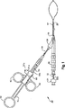
ここで、図面を参照して、内視鏡との使用のためのスネア注入デバイス10が図1中に示される。このデバイスは、ポリープ切除、ならびに注入およびスネア能力が要求される任意のその他の手順における使用のために適切である。図1において、このスネアは、拡張された位置で示される。図2は、デバイス10の遠位端の拡大された斜視図であり、拡張されたスネア60および展開されたニードル36を示す。このデバイスは、医師が器具チャネルからこのデバイスを取り出すことなくいずれの技法も実施することを可能にする。
Referring now to the drawings, a
このデバイスは、細長い二重の管腔12を含む。この二重の管腔は、第1のチャネル14および第2のチャネル16を有し、各チャネルは、近位端18から遠位端20まで至る。管腔12は、押し出されたプラスチックの単一片で示される。管腔12は、例えば、ポリテトラフロオロエチレン(PTFE)またはポリエチレン管材のような種々の可撓性材料から構築され得る。種々の第1および第2のチャネルサイズおよび形状が、本発明の実施において用いられ得る。さらに、本発明は、単一片の押し出された二重管腔管材とともに、またはそれに代わって、別個の管材およびシースまたはその他の適切な被覆を含む二重管腔アセンブリとともに実施され得ることは当業者に明らかである。
The device includes an elongated
身体内の組織に注入するような使用のための流体送達システムは、デバイス10の一部である。この送達システムは、管腔12の近位端18に固定された中空ベース30を含む。このベース30は、このベースを通って辿り、そしてそれに対して移動され得るアクチュエーターチューブ32のための支持を提供する。このチューブ32は、近位端33aおよび遠位端33b有する。示されるように、このチューブ32は、ベース30および第1のチャネル14を通って挿入される。
A fluid delivery system for use such as injecting into tissue within the body is part of the
このベース30は、側方入口ポート38をさらに含む。示されるように、このポート38は、ベース30の長軸方向軸に対して45゜より小さい角度をなす。この角度をなす構造は、二重管腔12内の結合を減少すると考えられる。得られるy形状のベースは、単一の成形片であるか、または2つのパーツのアセンブルされた片である。
The
アクチュエーターチューブ32は、中空ノブ34の移動によって操作され得る。このノブ34は、このアクチュエーターチューブ32近位端33aに固定される。ニードル36は、アクチュエーターチューブ32遠位端33bに固定されて示される。この位置では、流体溶液は、ノブを通ってニードルまで加圧下で通過され得る。
The
ここで図3および4を参照して、ニードル36の移動の範囲が示される。図3は、この10のデバイスの遠位端の断面図であり、格納位置にあるニードル36を示す。この静止位置においては、ニードル36に対して軸方向力はない。このニードルは、ニードルハウジング部材70内に配置される。示されるハウジングは、中空の内部、およびねじ山のある、ノッチのある、または間欠的にテーパー状である外面を備えた、細長い、バーブ(barb)継手70であるか、またはそうでなければ、改良された可撓性を提供するほぼ起伏のある本体である。当該技術分野で公知のその他の継手が用いられ得る。結果として、このニードルは、格納位置で管腔12の側壁を穿孔し得ない。
3 and 4, the range of movement of the
二重の管腔の遠位端20に隣接して、上記のバーブ70は、熱収縮されること、プレスばめ、結合、またはその他の適切な公知の方法によって適所に配置され得る。このバーブは、例えば、任意の被覆された金属、または中程度の硬度のプラスチックのような非伝導性の適切な材料から構築され得る。このバーブは、スネアにエネルギーを与えるために用いられル高周波エネルギーが、次に、標的とされた組織から離して電流を指向し得るよう、このバーブに移動しないように非伝導性であることが重要である。このバーブは、一緒に結合された2つ以上の片を含み得る。
Adjacent to the distal end 20 of the dual lumen, the
標的とする組織の視覚による識別の後、医師は、ニードルを組織中に突き出し、そして流体を注入する。突出位置にあるニードル36は、図4に示される。このニードル36を突き出す作動ステップは、ノブ34のニードル36の方向の操作である。ノブ34、アクチュエーターチューブ32およびニードル36はすべて、軸方向に1:1の距離関係で移動する。ニードルが突出する距離L1は、バーブ70の狭まった部分71を妨害するニードルストップ37よって予め決定される。この距離L1は、性能および安全規準によって決定され、そして本発明の実施において変動し得る。
After visual identification of the targeted tissue, the physician pushes the needle into the tissue and injects fluid. The
図4は、完全に突出した位置にあるこの狭い部分71と連続しているニードルストップ37のショルダーを示す。このストップ37および狭くなった部分71は、そもそも、ニードルがアクチュエーターチューブ32と離れるような場合に、このニードルが患者中に落ち込むことを防ぐ。
FIG. 4 shows the shoulder of the needle stop 37 that is continuous with this narrow portion 71 in the fully protruding position. This
このチューブ32とベース30との関係は、完全なニードル突出が起こるように、この細長い管腔12中の任意の関節性摩擦または損失移動を克服するためのさらなるストローク長さを有するような形態である。ノブ34が解放された後、ベース30の内部に配置されたスプリング機構(図示せず)が、ノブ34およびニードル36を押し、それらを図1に示されるような静止位置に戻す。
The relationship between the
組織を切除するためのスネアシステムは、デバイス10内に含まれる。このスネアシステムは、例えば、ポリープのような組織を、それが流体の注入により持ち上げられた後に除去するために用いられ得る。スネア60は、図3では折り畳まれた位置で示される。
A snare system for ablating tissue is included in
上記システムは、近位端に親指リング42を有する細長い本体40を含む。ハンドル50は、別個の片として本体40上に形成される。このハンドルは、2つの指リング52の操作によって遠位または近位方向のいずれかに、上記本体に対してスライド可能である。このベース40およびバンドル50は、剛直性のプラスチック材料から形成されるが、任意の適切な材料が本発明の実施において用いられ得る。
The system includes an elongate body 40 having a
スネアシステム10は、二重管腔12の第2のチャネル16を通って実質的に延びるケーブル54を含む。このケーブル54は、ハンドル42の固定される近位端55aおよびコネクター68に固定される遠位端55bを有する。示されるように、このケーブル50は、本体40を入口ポート38に遠隔に連結する可撓性チューブ44をさらに通過する。このチューブ44は、ポリエチレンのような任意の可撓性の耐久性のある材料から構築され得る。
The
図2および4は、拡張位置にあるスネア60を示す。このスネア60は、コネクター68によってケーブル54の遠位端に固定される。このスネア60は、図4および5で最も良く観察されるように、2つの端部62および64を有するワイヤループによって形成される。デバイス10の遠位端の拡大断面図が図5に示される。ワイヤが、ケーブル機構の過度の摩擦および結合を引き起こす交差およびねじれを防ぐために、ワイヤの長さL2は、熱収縮材料66によって結合される。この特徴はまた、コネクター68が第2のチャネル16の内側でより近位方向にあり、それがチューブ12遠位端20を出ないように位置決めされることを可能にする。この近位位置は、コネクター68がチューブ12を出、そして第2のチャネル16の内側への再侵入の際に、遠位端20に引っかかるいかなる機会をも防ぐ。
2 and 4 show the
一連の管腔を延ばすスペーサー80が、図3および4において第1のチャネル14中に示される。これらスペーサーは、プレスばめされ、接着され、熱挿入されまたは任意のその他の適切な方法であり得る。例示の目的のみのために合計5つの等しく間隔を置かれ、そして等しいサイズのスペーサーが示されるが、これらスペーサー80の数、サイズおよび間隔は、本発明の実施において変動し得る。最も遠位のスペーサーは、バーブ70の端部に軸方向に配置される。ニードル機構が機能するために十分なスペースを提供するために、バーブ70は、この遠位端部分の直径の半分以上を占める。その結果、このバーブは、このチューブの遠位部分で第1のチャネル12と第2のチャネル14とを分離する中央膜のたるみを引き起こす。これらスペーサー80は、示されるように、長さL3について第1のチャネル16のたるみの伸張を効率的に提供する。
A
このたるむ部分の伸張は、スネアループの進行のためのさらなる長さを提供する。特に、支持されていないワイヤ62、64のセクション、すなわち、熱収縮物66によって被覆されていないセクションは、第2のチャネル16内で上下にシフトし得る。このワイヤのシフト移動は、中央膜の遷移領域90を通って容易に遷移しない。それ故、上記スペーサー80は、減少した管腔のさらなる長さを提供し、その結果、支持されていないワイヤ62、64は、遷移領域に到達しない。
This slack stretch provides additional length for the progress of the snare loop. In particular, sections of
上記長さL3は、熱収縮物66、コネクター68、チューブ遠位端20、またはデバイス10のその他の構成要素に対してこれらスペーサーを位置決めがそうであるように、本発明の実施においては変動し得ることが、当業者によって理解されるべきである。
The length L 3 may vary in the practice of the present invention, such as positioning the spacers relative to the heat shrink 66, connector 68, tube distal end 20, or other components of the
本発明のいくつかの実施形態が示され、そして説明されているが、本発明は、開示される正確な構成に制限されるとみなされるべきではない。本発明の種々の適合、改変および使用が、本発明の当業者に想起され得る。添付の特許請求の範囲の範囲または思想内に入るすべてのこのような適合、改変および使用を包含することが意図される。 Although several embodiments of the present invention have been shown and described, the present invention should not be considered limited to the exact configuration disclosed. Various adaptations, modifications and uses of the invention may occur to those skilled in the art. It is intended to embrace all such adaptations, modifications and uses that fall within the scope or spirit of the appended claims.
Claims (12)
a)プラスチックの膜によって分離された第1のチャネルおよび第2のチャネルを有する細長い部材;
b)ニードルを該標的組織に挿入するためのニードルシステムであって、ニードル、中空アクチュエーターチューブ、およびチューブハンドルを備え、ここで、該チューブが該第1のチャネルを通って挿入されるニードルシステム;
c)該標的組織を切除するためのスネアシステムであって、スネア装置、作動ケーブル、およびスネアハンドルを備え、ここで該ケーブルが該第2のチャネルを通って挿入されるスネアシステム;
d)ベースであって、該チューブおよび該ケーブルがそれを通って経路をとるベース;ならびに
e)該ニードルが弛緩位置にあるとき、該ニードルと該細長い部材との間に位置決めされる可撓性のニードルハウジング;を備え、
f)ここで、該ニードルハウジングは可撓性の細長いバーブであり、そして連続的内表面を有し、そして該ニードルが該プラスチックの膜を貫通することを防ぎ、
g)さらに、該可撓性の細長いバーブが該第1のチャネルの遠位端内に配置され、そして該細長い部材の遠位端部分の直径の半分より多くを占め、該バーブの長さに沿って該プラスチックの膜のたるみを引き起こす、スネア注入デバイス。A snare injection device for performing an endoscopic procedure for removing target tissue comprising:
a) an elongate member having a first channel and a second channel separated by a plastic membrane;
b) a needle system for inserting a needle into the target tissue comprising a needle, a hollow actuator tube, and a tube handle, wherein the tube is inserted through the first channel;
c) a snare system for excising the target tissue comprising a snare device, an actuation cable, and a snare handle, wherein the cable is inserted through the second channel;
d) a base wherein the tube and the cable are routed therethrough; and e) a flexibility positioned between the needle and the elongate member when the needle is in a relaxed position. A needle housing;
f) where the needle housing is a flexible elongated barb and has a continuous inner surface and prevents the needle from penetrating the plastic membrane;
g) Further, the flexible elongated barb is disposed within the distal end of the first channel and occupies more than half of the diameter of the distal end portion of the elongated member, the length of the barb Snare infusion device that causes sagging of the plastic film along .
a)プラスチックの膜によって分離された第1のチャネルおよび第2のチャネルを有する細長い部材;
b)ニードルを該標的組織に挿入するためのニードルシステムであって、ニードル、中空アクチュエーターチューブ、およびチューブハンドルを備え、ここで、該チューブが該第1のチャネルを通って挿入されるニードルシステム;
c)該標的組織を切除するためのスネアシステムであって、スネア装置、作動ケーブル、およびスネアハンドルを備え、ここで該ケーブルが該第2のチャネルを通って挿入されるスネアシステム;
d)ベースであって、該チューブおよび該ケーブルがそれを通って経路をとるベース;ならびに
e)該ニードルが弛緩位置にあるとき、該ニードルと該細長い部材との間に位置決めされる可撓性ニードルハウジング;を備え、
f)ここで、該ニードルハウジングは、該ニードルハウジングの長さに沿って該第1のチャネルの断面領域と該第2のチャネルの断面領域との間で一定の比を維持するためのスペーサーとして作用する可撓性の細長いバーブであり、該バーブが、該バーブの長さに沿って該プラスチックの膜のたるみを引き起こす、スネア注入デバイス。A snare injection device for performing an endoscopic procedure for removing target tissue comprising:
a) an elongate member having a first channel and a second channel separated by a plastic membrane;
b) a needle system for inserting a needle into the target tissue comprising a needle, a hollow actuator tube, and a tube handle, wherein the tube is inserted through the first channel;
c) a snare system for excising the target tissue comprising a snare device, an actuation cable, and a snare handle, wherein the cable is inserted through the second channel;
d) a base, the base takes the path the tube and the cable therethrough; flexible when and e) the needle is in a relaxed position, Ru is positioned between the needle and the elongate member A needle housing;
f) wherein said needle housing, as a spacer for maintaining a constant ratio between the cross-sectional area and the second channel of the cross-sectional area of the first channel along the length of the needle housing A snare infusion device , which is an actuating flexible elongated barb that causes sagging of the plastic film along the length of the barb .
内視鏡器具のチャネル中への挿入のために適合され、そしてプラスチックの膜によって分離された第1のチャネルおよび第2のチャネルを有する細長い部材;
ニードルを該標的組織に挿入するためのニードルシステムであって、ニードル、中空アクチュエーターチューブ、およびチューブハンドルを備え、ここで、該チューブが該第1のチャネルを通って挿入されるニードルシステム;
該標的組織を切除するためのスネアシステムであって、スネア装置、作動ケーブル、およびスネアハンドルを備え、ここで該ケーブルが該第2のチャネルを通って挿入されるスネアシステム;
ベースであって、該チューブおよび該ケーブルがそれを通って経路をとるベース;ならびに
該第1のチャネルの遠位端に位置決めされる可撓性ニードルハウジング;を備え、
ここで、該ニードルハウジングは可撓性の細長いバーブであって、かつ連続的内表面を有し、そして該ニードルが該プラスチックの膜を貫通することを防ぎ、
さらに、該ニードルハウジングが、該第1のチャネルの遠位端内に配置され、そして該細長い部材の遠位端部分の直径の半分より多くを占め、該バーブの長さに沿って該プラスチックの膜のたるみを引き起こす、スネア注入デバイス。A snare injection device for performing an endoscopic procedure for removing target tissue comprising:
An elongate member adapted for insertion into a channel of an endoscopic instrument and having a first channel and a second channel separated by a plastic membrane;
A needle system for inserting a needle into the target tissue comprising a needle, a hollow actuator tube, and a tube handle, wherein the tube is inserted through the first channel;
A snare system for ablating the target tissue, the snare system comprising a snare device, an actuation cable, and a snare handle, wherein the cable is inserted through the second channel;
A base through which the tube and the cable route; and a flexible needle housing positioned at the distal end of the first channel;
Wherein the needle housing is a flexible elongated barb and has a continuous inner surface and prevents the needle from penetrating the plastic membrane;
Furthermore, the needle housing is disposed within a distal end of said first channel, and accounts for more than half the diameter of the distal end portion of the elongated member, of the plastic along the length of the barb A snare injection device that causes sagging of the membrane .
Applications Claiming Priority (3)
| Application Number | Priority Date | Filing Date | Title |
|---|---|---|---|
| US57407304P | 2004-05-25 | 2004-05-25 | |
| US60/574,073 | 2004-05-25 | ||
| PCT/US2005/018294 WO2005115116A2 (en) | 2004-05-25 | 2005-05-25 | Snare injection device |
Publications (2)
| Publication Number | Publication Date |
|---|---|
| JP2008500111A JP2008500111A (en) | 2008-01-10 |
| JP4977017B2 true JP4977017B2 (en) | 2012-07-18 |
Family
ID=35451339
Family Applications (1)
| Application Number | Title | Priority Date | Filing Date |
|---|---|---|---|
| JP2007515282A Active JP4977017B2 (en) | 2004-05-25 | 2005-05-25 | Snare injection device |
Country Status (4)
| Country | Link |
|---|---|
| US (1) | US7691110B2 (en) |
| EP (1) | EP1766476B1 (en) |
| JP (1) | JP4977017B2 (en) |
| WO (1) | WO2005115116A2 (en) |
Families Citing this family (35)
| Publication number | Priority date | Publication date | Assignee | Title |
|---|---|---|---|---|
| US6814739B2 (en) | 2001-05-18 | 2004-11-09 | U.S. Endoscopy Group, Inc. | Retrieval device |
| CA2617167A1 (en) * | 2005-08-04 | 2007-02-15 | C.R. Bard, Inc. | Implant introducer |
| JP2009515564A (en) | 2005-08-04 | 2009-04-16 | シー・アール・バード・インコーポレイテツド | Pelvic implant system and method |
| WO2007059199A2 (en) | 2005-11-14 | 2007-05-24 | C.R. Bard, Inc. | Sling anchor system |
| US8480559B2 (en) | 2006-09-13 | 2013-07-09 | C. R. Bard, Inc. | Urethral support system |
| EP2109392B1 (en) * | 2007-01-29 | 2018-03-07 | U.S. Endoscopy Group, Inc. | Endoscopic device |
| US8591521B2 (en) | 2007-06-08 | 2013-11-26 | United States Endoscopy Group, Inc. | Retrieval device |
| US8480651B2 (en) * | 2007-08-02 | 2013-07-09 | Covidien Lp | Cannula system |
| US8206280B2 (en) | 2007-11-13 | 2012-06-26 | C. R. Bard, Inc. | Adjustable tissue support member |
| US20090287080A1 (en) * | 2008-05-15 | 2009-11-19 | Olympus Medical Systems Corp. | Treatment instrument for endoscope and lymph node removing method |
| EP2279773B1 (en) * | 2008-05-22 | 2013-01-23 | Terumo Kabushiki Kaisha | Catheter retaining tool |
| USD668330S1 (en) * | 2009-05-15 | 2012-10-02 | Henke-Sass, Wolf Gmbh | Injectors |
| US9204868B2 (en) | 2011-12-02 | 2015-12-08 | Interscope, Inc. | Methods and apparatus for removing material from within a mammalian cavity using an insertable endoscopic instrument |
| US9033895B2 (en) | 2011-12-02 | 2015-05-19 | Interscope, Inc. | Endoscope including an torque generation component or torque delivery component disposed within an insertable portion of the endoscope and a surgical cutting assembly insertable within the endoscope |
| US9808146B2 (en) | 2011-12-02 | 2017-11-07 | Interscope, Inc. | Endoscopic tool for debriding and removing polyps |
| US9033864B2 (en) | 2011-12-02 | 2015-05-19 | Interscope, Inc. | Endoscope including a torque generation component or torque delivery component disposed within an insertable portion of the endoscope and a surgical cutting assembly insertable within the endoscope |
| US9028424B2 (en) | 2011-12-02 | 2015-05-12 | Interscope, Inc. | Endoscope including a torque generation component or torque delivery component disposed within an insertable portion of the endoscope and a surgical cutting assembly insertable within the endoscope |
| US8882680B2 (en) | 2011-12-02 | 2014-11-11 | Interscope, Inc. | Insertable endoscopic instrument for tissue removal |
| US11076840B2 (en) | 2011-12-02 | 2021-08-03 | Interscope, Inc. | Surgical console, specimen receiver, and insertable endoscopic instrument for tissue removal |
| USD855802S1 (en) | 2011-12-23 | 2019-08-06 | Interscope, Inc. | Disposable tool |
| DE102012223076A1 (en) * | 2012-12-13 | 2014-07-03 | Geuder Ag | Instrument for stimulation or irritation and / or for abrasive treatment and / or for polishing a membrane or surface or inner surface in the human or animal eye |
| US9486303B2 (en) | 2013-03-14 | 2016-11-08 | Cook Medical Technologies Llc | Implantable medical device retrieval system, apparatus, and method |
| US9572591B2 (en) | 2013-09-03 | 2017-02-21 | United States Endoscopy Group, Inc. | Endoscopic snare device |
| US9872700B2 (en) | 2013-09-03 | 2018-01-23 | United States Endoscopy Group, Inc. | Endoscopic snare device |
| US9398945B2 (en) | 2013-09-19 | 2016-07-26 | Cook Medical Technologies Llc | Vascular implant retrieval assembly and method |
| EP3060137B8 (en) * | 2013-10-25 | 2019-03-13 | Creganna Unlimited Company | Transseptal crossing needle device |
| CN104622566A (en) * | 2015-01-23 | 2015-05-20 | 诸暨市鹏天医疗器械有限公司 | Electric snare allowing water injection |
| JP7015782B2 (en) * | 2015-11-25 | 2022-02-03 | ジャイラス エーシーエムアイ インク | Sheath for needle delivery |
| CN105615948A (en) * | 2016-03-09 | 2016-06-01 | 袁捷 | Gastrointestinal endoscope biopsy channel operating instrument |
| US10667838B2 (en) | 2017-01-09 | 2020-06-02 | United States Endoscopy Group, Inc. | Endoscopic snare device |
| EP3954310A1 (en) | 2017-02-10 | 2022-02-16 | United States Endoscopy Group, Inc. | Snare injection device |
| CN108670403A (en) * | 2018-06-04 | 2018-10-19 | 安瑞医疗器械(杭州)有限公司 | A kind of band rinses the snare of spraying function |
| KR102209398B1 (en) * | 2019-01-14 | 2021-02-01 | (주)비엠에이 | Polyps removable and collectable endoscope sugical instrument |
| CN109771003B (en) * | 2019-03-18 | 2024-02-06 | 刘卫辉 | Medical multifunctional tissue snare |
| EP4017384A1 (en) * | 2019-08-22 | 2022-06-29 | Edwards Lifesciences Corporation | Puncture needles |
Family Cites Families (44)
| Publication number | Priority date | Publication date | Assignee | Title |
|---|---|---|---|---|
| US5009642A (en) | 1987-09-28 | 1991-04-23 | Bio-Plexus, Inc. | Self-blunting needle assembly for use with a catheter, and catheter assembly using the same |
| US4966589A (en) * | 1988-11-14 | 1990-10-30 | Hemedix International, Inc. | Intravenous catheter placement device |
| JP2800060B2 (en) | 1989-11-14 | 1998-09-21 | 日本板硝子株式会社 | Method for manufacturing semiconductor film |
| US5527292A (en) * | 1990-10-29 | 1996-06-18 | Scimed Life Systems, Inc. | Intravascular device for coronary heart treatment |
| US5156590A (en) | 1991-06-24 | 1992-10-20 | Wolfgang Vilmar | Uretero-renoscope with catheter body having plural partitioned inner conduits |
| US5190542A (en) | 1991-11-05 | 1993-03-02 | Nakao Naomi L | Surgical retrieval assembly and related method |
| US5759187A (en) | 1991-11-05 | 1998-06-02 | Wilk & Nakao Medical Technology, Incorporated | Surgical retrieval assembly and associated method |
| US5997547A (en) * | 1991-11-05 | 1999-12-07 | Nakao; Naomi L. | Surgical retrieval assembly and associated method |
| US5201740A (en) | 1991-11-05 | 1993-04-13 | Nakao Naomi L | Surgical retrieval assembly and related method |
| US5741271A (en) | 1991-11-05 | 1998-04-21 | Nakao; Naomi L. | Surgical retrieval assembly and associated method |
| US5486182A (en) * | 1991-11-05 | 1996-01-23 | Wilk & Nakao Medical Technology Inc. | Polyp retrieval assembly with separable web member |
| US5374273A (en) | 1992-10-05 | 1994-12-20 | Nakao; Naomi L. | Method for retrieval of retained common bile duct stones |
| US5336227A (en) | 1991-11-05 | 1994-08-09 | Wilk & Nakao Medical Technology Incorporated | Surgical cauterization snare with polyp capturing web net |
| JP3250621B2 (en) | 1992-02-07 | 2002-01-28 | オリンパス光学工業株式会社 | Endoscope treatment tool |
| US5417697A (en) | 1993-07-07 | 1995-05-23 | Wilk; Peter J. | Polyp retrieval assembly with cauterization loop and suction web |
| US5423830A (en) | 1993-07-07 | 1995-06-13 | Schneebaum; Cary W. | Polyp retrieval method and associated instrument assembly |
| US5542948A (en) | 1994-05-24 | 1996-08-06 | Arrow Precision Products, Inc. | Surgical combination inject and snare apparatus |
| US5846248A (en) | 1995-04-13 | 1998-12-08 | Boston Scientific Corporation | Method and apparatus for severing and capturing polyps |
| US5666970A (en) * | 1995-05-02 | 1997-09-16 | Heart Rhythm Technologies, Inc. | Locking mechanism for catheters |
| US5964740A (en) * | 1996-07-09 | 1999-10-12 | Asahi Kogaku Kogyo Kabushiki Kaisha | Treatment accessory for an endoscope |
| US6190353B1 (en) * | 1995-10-13 | 2001-02-20 | Transvascular, Inc. | Methods and apparatus for bypassing arterial obstructions and/or performing other transvascular procedures |
| US5810776A (en) * | 1996-02-13 | 1998-09-22 | Imagyn Medical, Inc. | Method and apparatus for performing laparoscopy |
| US5906621A (en) * | 1996-05-14 | 1999-05-25 | United States Endoscopy Group, Inc. | Endoscopic surgical device |
| US5785689A (en) * | 1996-07-18 | 1998-07-28 | Act Medical, Inc. | Endoscopic catheter sheath position control |
| US6827710B1 (en) * | 1996-11-26 | 2004-12-07 | Edwards Lifesciences Corporation | Multiple lumen access device |
| US5906594A (en) * | 1997-01-08 | 1999-05-25 | Symbiosis Corporation | Endoscopic infusion needle having dual distal stops |
| JP3730757B2 (en) | 1997-07-30 | 2006-01-05 | オリンパス株式会社 | Endoscopic treatment tool |
| JP4157183B2 (en) * | 1998-02-17 | 2008-09-24 | オリンパス株式会社 | Endoscopic treatment tool |
| US5961526A (en) * | 1998-02-18 | 1999-10-05 | Boston Scientific Corporation | Coaxial needle and severing snare |
| US6623474B1 (en) * | 1998-06-04 | 2003-09-23 | Biosense Webster, Inc. | Injection catheter with needle stop |
| US6352503B1 (en) | 1998-07-17 | 2002-03-05 | Olympus Optical Co., Ltd. | Endoscopic surgery apparatus |
| JP3244660B2 (en) * | 1998-08-17 | 2002-01-07 | 旭光学工業株式会社 | Endoscope treatment tool |
| US6007546A (en) * | 1998-10-26 | 1999-12-28 | Boston Scientific Ltd. | Injection snare |
| US6162209A (en) * | 1998-11-17 | 2000-12-19 | Scimed Life Systems, Inc. | Multi-function surgical instrument tool actuator assembly |
| US6371963B1 (en) * | 1998-11-17 | 2002-04-16 | Scimed Life Systems, Inc. | Device for controlled endoscopic penetration of injection needle |
| JP2000175930A (en) * | 1998-12-18 | 2000-06-27 | Fuji Photo Optical Co Ltd | Paracentesis treating implement |
| JP2000316868A (en) * | 1999-05-10 | 2000-11-21 | Fuji Photo Optical Co Ltd | Treatment apparatus for endoscope |
| JP4360713B2 (en) * | 1999-06-03 | 2009-11-11 | Hoya株式会社 | Endoscope snare |
| JP4331869B2 (en) * | 1999-06-24 | 2009-09-16 | 株式会社根本杏林堂 | Autologous blood perfusion device for coronary artery bypass surgery under heart beat |
| JP3679674B2 (en) | 2000-02-03 | 2005-08-03 | オリンパス株式会社 | Endoscope |
| US6527753B2 (en) | 2000-02-29 | 2003-03-04 | Olympus Optical Co., Ltd. | Endoscopic treatment system |
| US7037291B2 (en) * | 2001-12-04 | 2006-05-02 | Advanced Cardiovascular Systems, Inc. | Catheter shaft junction having a polymeric reinforcing member with a high glass transition temperature |
| US6736812B2 (en) * | 2002-06-19 | 2004-05-18 | Scimed Life Systems, Inc. | Dual short throw advancer/retractor |
| US6945956B2 (en) * | 2002-12-23 | 2005-09-20 | Medtronic, Inc. | Steerable catheter |
-
2005
- 2005-05-25 JP JP2007515282A patent/JP4977017B2/en active Active
- 2005-05-25 EP EP05755966.8A patent/EP1766476B1/en active Active
- 2005-05-25 WO PCT/US2005/018294 patent/WO2005115116A2/en active Application Filing
- 2005-05-25 US US11/137,814 patent/US7691110B2/en active Active
Also Published As
| Publication number | Publication date |
|---|---|
| EP1766476A2 (en) | 2007-03-28 |
| US20050267490A1 (en) | 2005-12-01 |
| EP1766476B1 (en) | 2013-11-06 |
| US7691110B2 (en) | 2010-04-06 |
| EP1766476A4 (en) | 2012-07-04 |
| WO2005115116A3 (en) | 2007-08-23 |
| JP2008500111A (en) | 2008-01-10 |
| WO2005115116A2 (en) | 2005-12-08 |
Similar Documents
| Publication | Publication Date | Title |
|---|---|---|
| JP4977017B2 (en) | Snare injection device | |
| JP5318783B2 (en) | Endoscope device | |
| US7635374B2 (en) | Endoscopic full thickness resection using surgical compression clips | |
| US9872600B2 (en) | Tissue resection bander and related methods of use | |
| EP2658456B1 (en) | Snare with retractable engaging members | |
| US20140276810A1 (en) | Devices for tissue resection | |
| JP2007296349A (en) | Integrated guidewire needle knife device | |
| US9539055B2 (en) | Resection device with support mechanism and related methods of use | |
| US20140257321A1 (en) | Resection device and related methods of use | |
| EP3954310A1 (en) | Snare injection device | |
| US10548626B2 (en) | Endoscopic tissue manipulation tool | |
| JP6874001B2 (en) | Medical equipment and usage | |
| US20140276814A1 (en) | Tissue resection device and related methods of use | |
| WO2024054831A2 (en) | Endoscopic open wire snare system |
Legal Events
| Date | Code | Title | Description |
|---|---|---|---|
| A621 | Written request for application examination |
Free format text: JAPANESE INTERMEDIATE CODE: A621 Effective date: 20080509 |
|
| A131 | Notification of reasons for refusal |
Free format text: JAPANESE INTERMEDIATE CODE: A131 Effective date: 20110107 |
|
| A601 | Written request for extension of time |
Free format text: JAPANESE INTERMEDIATE CODE: A601 Effective date: 20110322 |
|
| A602 | Written permission of extension of time |
Free format text: JAPANESE INTERMEDIATE CODE: A602 Effective date: 20110329 |
|
| A521 | Request for written amendment filed |
Free format text: JAPANESE INTERMEDIATE CODE: A523 Effective date: 20110420 |
|
| A521 | Request for written amendment filed |
Free format text: JAPANESE INTERMEDIATE CODE: A821 Effective date: 20110420 |
|
| A131 | Notification of reasons for refusal |
Free format text: JAPANESE INTERMEDIATE CODE: A131 Effective date: 20110729 |
|
| A601 | Written request for extension of time |
Free format text: JAPANESE INTERMEDIATE CODE: A601 Effective date: 20111028 |
|
| A602 | Written permission of extension of time |
Free format text: JAPANESE INTERMEDIATE CODE: A602 Effective date: 20111107 |
|
| A521 | Request for written amendment filed |
Free format text: JAPANESE INTERMEDIATE CODE: A523 Effective date: 20120130 |
|
| TRDD | Decision of grant or rejection written | ||
| A01 | Written decision to grant a patent or to grant a registration (utility model) |
Free format text: JAPANESE INTERMEDIATE CODE: A01 Effective date: 20120409 |
|
| A01 | Written decision to grant a patent or to grant a registration (utility model) |
Free format text: JAPANESE INTERMEDIATE CODE: A01 |
|
| A61 | First payment of annual fees (during grant procedure) |
Free format text: JAPANESE INTERMEDIATE CODE: A61 Effective date: 20120413 |
|
| R150 | Certificate of patent or registration of utility model |
Ref document number: 4977017 Country of ref document: JP Free format text: JAPANESE INTERMEDIATE CODE: R150 Free format text: JAPANESE INTERMEDIATE CODE: R150 |
|
| FPAY | Renewal fee payment (event date is renewal date of database) |
Free format text: PAYMENT UNTIL: 20150420 Year of fee payment: 3 |
|
| R250 | Receipt of annual fees |
Free format text: JAPANESE INTERMEDIATE CODE: R250 |
|
| R250 | Receipt of annual fees |
Free format text: JAPANESE INTERMEDIATE CODE: R250 |
|
| R250 | Receipt of annual fees |
Free format text: JAPANESE INTERMEDIATE CODE: R250 |
|
| R250 | Receipt of annual fees |
Free format text: JAPANESE INTERMEDIATE CODE: R250 |
|
| R250 | Receipt of annual fees |
Free format text: JAPANESE INTERMEDIATE CODE: R250 |
|
| R250 | Receipt of annual fees |
Free format text: JAPANESE INTERMEDIATE CODE: R250 |
|
| R250 | Receipt of annual fees |
Free format text: JAPANESE INTERMEDIATE CODE: R250 |
|
| R250 | Receipt of annual fees |
Free format text: JAPANESE INTERMEDIATE CODE: R250 |
|
| R250 | Receipt of annual fees |
Free format text: JAPANESE INTERMEDIATE CODE: R250 |
|
| R250 | Receipt of annual fees |
Free format text: JAPANESE INTERMEDIATE CODE: R250 |