JP4976485B2 - Scanning treatment laser with swept beam spot and universal carriage - Google Patents
Scanning treatment laser with swept beam spot and universal carriage Download PDFInfo
- Publication number
- JP4976485B2 JP4976485B2 JP2009506591A JP2009506591A JP4976485B2 JP 4976485 B2 JP4976485 B2 JP 4976485B2 JP 2009506591 A JP2009506591 A JP 2009506591A JP 2009506591 A JP2009506591 A JP 2009506591A JP 4976485 B2 JP4976485 B2 JP 4976485B2
- Authority
- JP
- Japan
- Prior art keywords
- laser
- laser device
- carriage
- optical element
- pat
- Prior art date
- Legal status (The legal status is an assumption and is not a legal conclusion. Google has not performed a legal analysis and makes no representation as to the accuracy of the status listed.)
- Active
Links
- 238000011282 treatment Methods 0.000 title description 17
- 230000003287 optical effect Effects 0.000 claims description 21
- 239000004065 semiconductor Substances 0.000 claims description 5
- 210000004209 hair Anatomy 0.000 description 10
- 210000001519 tissue Anatomy 0.000 description 9
- 210000003128 head Anatomy 0.000 description 8
- 210000004761 scalp Anatomy 0.000 description 8
- 230000003779 hair growth Effects 0.000 description 7
- 238000000034 method Methods 0.000 description 7
- 238000007443 liposuction Methods 0.000 description 6
- 210000003491 skin Anatomy 0.000 description 5
- 206010061218 Inflammation Diseases 0.000 description 4
- 208000002193 Pain Diseases 0.000 description 4
- 230000008859 change Effects 0.000 description 4
- 230000004054 inflammatory process Effects 0.000 description 4
- 238000013532 laser treatment Methods 0.000 description 4
- 238000009196 low level laser therapy Methods 0.000 description 4
- 238000001228 spectrum Methods 0.000 description 4
- 230000000638 stimulation Effects 0.000 description 4
- 230000008901 benefit Effects 0.000 description 3
- 238000010586 diagram Methods 0.000 description 3
- 230000001225 therapeutic effect Effects 0.000 description 3
- 230000004913 activation Effects 0.000 description 2
- 210000003205 muscle Anatomy 0.000 description 2
- 230000002980 postoperative effect Effects 0.000 description 2
- 230000005855 radiation Effects 0.000 description 2
- 210000002435 tendon Anatomy 0.000 description 2
- 206010030113 Oedema Diseases 0.000 description 1
- 208000004550 Postoperative Pain Diseases 0.000 description 1
- 230000000712 assembly Effects 0.000 description 1
- 238000000429 assembly Methods 0.000 description 1
- 230000003796 beauty Effects 0.000 description 1
- 230000001764 biostimulatory effect Effects 0.000 description 1
- 239000003795 chemical substances by application Substances 0.000 description 1
- 238000009232 chiropractic Methods 0.000 description 1
- 230000001066 destructive effect Effects 0.000 description 1
- 201000010099 disease Diseases 0.000 description 1
- 208000037265 diseases, disorders, signs and symptoms Diseases 0.000 description 1
- 239000003814 drug Substances 0.000 description 1
- 229940079593 drug Drugs 0.000 description 1
- 230000000694 effects Effects 0.000 description 1
- 239000000835 fiber Substances 0.000 description 1
- 210000003780 hair follicle Anatomy 0.000 description 1
- CPBQJMYROZQQJC-UHFFFAOYSA-N helium neon Chemical compound [He].[Ne] CPBQJMYROZQQJC-UHFFFAOYSA-N 0.000 description 1
- 239000005556 hormone Substances 0.000 description 1
- 229940088597 hormone Drugs 0.000 description 1
- 238000002647 laser therapy Methods 0.000 description 1
- 230000004048 modification Effects 0.000 description 1
- 238000012986 modification Methods 0.000 description 1
- 230000008439 repair process Effects 0.000 description 1
- 230000003252 repetitive effect Effects 0.000 description 1
- 230000004936 stimulating effect Effects 0.000 description 1
- 238000001356 surgical procedure Methods 0.000 description 1
- 238000010408 sweeping Methods 0.000 description 1
- 238000002560 therapeutic procedure Methods 0.000 description 1
- 230000003813 thin hair Effects 0.000 description 1
- 238000011269 treatment regimen Methods 0.000 description 1
- 230000029663 wound healing Effects 0.000 description 1
Images


Classifications
-
- A—HUMAN NECESSITIES
- A61—MEDICAL OR VETERINARY SCIENCE; HYGIENE
- A61N—ELECTROTHERAPY; MAGNETOTHERAPY; RADIATION THERAPY; ULTRASOUND THERAPY
- A61N5/00—Radiation therapy
- A61N5/06—Radiation therapy using light
- A61N5/0613—Apparatus adapted for a specific treatment
- A61N5/0616—Skin treatment other than tanning
-
- A—HUMAN NECESSITIES
- A61—MEDICAL OR VETERINARY SCIENCE; HYGIENE
- A61N—ELECTROTHERAPY; MAGNETOTHERAPY; RADIATION THERAPY; ULTRASOUND THERAPY
- A61N5/00—Radiation therapy
- A61N5/06—Radiation therapy using light
-
- A—HUMAN NECESSITIES
- A61—MEDICAL OR VETERINARY SCIENCE; HYGIENE
- A61N—ELECTROTHERAPY; MAGNETOTHERAPY; RADIATION THERAPY; ULTRASOUND THERAPY
- A61N5/00—Radiation therapy
- A61N5/06—Radiation therapy using light
- A61N5/067—Radiation therapy using light using laser light
-
- A—HUMAN NECESSITIES
- A61—MEDICAL OR VETERINARY SCIENCE; HYGIENE
- A61B—DIAGNOSIS; SURGERY; IDENTIFICATION
- A61B18/00—Surgical instruments, devices or methods for transferring non-mechanical forms of energy to or from the body
- A61B18/18—Surgical instruments, devices or methods for transferring non-mechanical forms of energy to or from the body by applying electromagnetic radiation, e.g. microwaves
- A61B18/20—Surgical instruments, devices or methods for transferring non-mechanical forms of energy to or from the body by applying electromagnetic radiation, e.g. microwaves using laser
- A61B2018/2035—Beam shaping or redirecting; Optical components therefor
- A61B2018/20351—Scanning mechanisms
- A61B2018/20355—Special scanning path or conditions, e.g. spiral, raster or providing spot overlap
-
- A—HUMAN NECESSITIES
- A61—MEDICAL OR VETERINARY SCIENCE; HYGIENE
- A61N—ELECTROTHERAPY; MAGNETOTHERAPY; RADIATION THERAPY; ULTRASOUND THERAPY
- A61N5/00—Radiation therapy
- A61N5/06—Radiation therapy using light
- A61N2005/0635—Radiation therapy using light characterised by the body area to be irradiated
- A61N2005/0642—Irradiating part of the body at a certain distance
-
- A—HUMAN NECESSITIES
- A61—MEDICAL OR VETERINARY SCIENCE; HYGIENE
- A61N—ELECTROTHERAPY; MAGNETOTHERAPY; RADIATION THERAPY; ULTRASOUND THERAPY
- A61N5/00—Radiation therapy
- A61N5/06—Radiation therapy using light
- A61N2005/0658—Radiation therapy using light characterised by the wavelength of light used
- A61N2005/0659—Radiation therapy using light characterised by the wavelength of light used infrared
-
- A—HUMAN NECESSITIES
- A61—MEDICAL OR VETERINARY SCIENCE; HYGIENE
- A61N—ELECTROTHERAPY; MAGNETOTHERAPY; RADIATION THERAPY; ULTRASOUND THERAPY
- A61N5/00—Radiation therapy
- A61N5/06—Radiation therapy using light
- A61N5/0613—Apparatus adapted for a specific treatment
- A61N5/0616—Skin treatment other than tanning
- A61N5/0617—Hair treatment
Landscapes
- Health & Medical Sciences (AREA)
- Engineering & Computer Science (AREA)
- Biomedical Technology (AREA)
- Life Sciences & Earth Sciences (AREA)
- General Health & Medical Sciences (AREA)
- Nuclear Medicine, Radiotherapy & Molecular Imaging (AREA)
- Animal Behavior & Ethology (AREA)
- Pathology (AREA)
- Public Health (AREA)
- Veterinary Medicine (AREA)
- Radiology & Medical Imaging (AREA)
- Biophysics (AREA)
- Physics & Mathematics (AREA)
- Optics & Photonics (AREA)
- Radiation-Therapy Devices (AREA)
- Mechanical Optical Scanning Systems (AREA)
- Laser Surgery Devices (AREA)
- Lenses (AREA)
Description
本発明はレーザー光を利用した医療及びカイロプラクティック装置に関する。より具体的に、本発明はビームスポットを掃引する走査型ヘッドを組み込んだ治療レーザー装置に関する。 The present invention relates to medical and chiropractic devices using laser light. More specifically, the present invention relates to a therapeutic laser device incorporating a scanning head that sweeps a beam spot.
低レベルレーザー治療(Low level laser therapy:LLLT)は様々な疾患の治療において低レベルレーザーエネルギーを利用する治療方法である。LLLTは創傷治癒を高め、浮腫を軽減し、様々な病因の疼痛を緩和するものであり、用途として、脂肪吸引術後の炎症及び疼痛を軽減するのに成功している。LLLTは、また脂肪吸引術後でだけではなく術中にも使用され、細胞間脂肪を細胞間隙に遊離させることによって脂肪の除去を促進する。LLLTはまた損傷した筋肉及び腱の治療及び修復、及び毛髪成長刺激のためにも使用される。 Low level laser therapy (LLLT) is a treatment method that utilizes low level laser energy in the treatment of various diseases. LLLT enhances wound healing, reduces edema, alleviates pain of various etiologies, and has been successfully used to reduce inflammation and pain after liposuction. LLLT is also used not only after liposuction but also during surgery to promote fat removal by releasing intercellular fat into the interstitial space. LLLT is also used to treat and repair damaged muscles and tendons, and stimulate hair growth.
LLLT治療は即時に検知できる治療組織の温度上昇や肉眼的に明らかな組織構造変化を生じさせない程度のエネルギー線量率を有する。結果的に治療された組織及び周辺の組織は加熱されず損傷されない。レーザー治療には多数の変数があり、レーザービームの波長、レーザービームに影響された範囲、レーザーエネルギー、パルス周波数、治療期間、及び組織特性を含む。各治療の成功はこれらの変数の関係及び組み合わせに依存する。例えば、脂肪吸引はある波長及び治療持続時間を使用するレジメンで進められてもよいし、一方疼痛は異なる波長及び治療持続時間を使用するレジメンにて治療され、炎症は第3のレジメンにて治療されてもよい。各治療法に対して特定の装置が当該技術分野において知られている。 The LLLT treatment has an energy dose rate that does not cause an increase in the temperature of the treated tissue that can be detected immediately or a change in the tissue structure that is clearly visible to the naked eye. As a result, the treated tissue and the surrounding tissue are not heated and are not damaged. There are a number of variables in laser treatment, including the wavelength of the laser beam, the range affected by the laser beam, laser energy, pulse frequency, treatment duration, and tissue characteristics. The success of each treatment depends on the relationship and combination of these variables. For example, liposuction may proceed with a regimen that uses a certain wavelength and duration of treatment, while pain is treated with a regimen that uses a different wavelength and duration of treatment, and inflammation is treated with a third regimen. May be. Specific devices for each therapy are known in the art.
レーザー治療はまた毛髪の成長を止める又は無用な毛髪を除く除毛剤としても使用される。しかしながら、これらの装置は比較的高いレベルのレーザーエネルギーを使用しており、熱によって不快な毛包を破壊する。Millerによる米国特許第5,630,811号明細書は無用な毛髪を除くのに使用されるレーザーの発展について記載している。 Laser treatment is also used as a hair removal agent to stop hair growth or remove unwanted hair. However, these devices use relatively high levels of laser energy and destroy unpleasant hair follicles with heat. US Pat. No. 5,630,811 to Miller describes the development of a laser used to remove unwanted hair.
破壊的な結果を生む高レベルレーザーエネルギーのためレーザーは毛髪除去にだけに使用できるという以前から受け入れられていた考えとは対照的に、LLLTは近年、育毛方法としても認められている。育毛を促進する低レベルレーザー治療の生物刺激効果を利用するように設計されたある装置がスイス、ジュネーブのInca Asset Management S.A.に譲渡された国際出願第WO02098509号に記載されている。この特許出願は天蓋又はヘルメットを記載しており、このヘルメットは美容室のヘアードライヤーとして使用されるヘルメットに似ている。前記装置は台上に支えられ、患者の頭上に位置づけされる。4分の1周ほど前後に回転できるように、ヘルメット様装置が天蓋内に置かれる。 In contrast to the previously accepted idea that lasers can only be used for hair removal because of the high level of laser energy that produces destructive results, LLLT has recently been recognized as a method of hair growth. One device designed to take advantage of the biostimulatory effects of low-level laser treatment to promote hair growth is Inca Asset Management S., Geneva, Switzerland. A. International Application No. WO02098509 assigned to. This patent application describes a canopy or helmet, which is similar to a helmet used as a hair dryer in a beauty salon. The device is supported on a table and positioned over the patient's head. A helmet-like device is placed in the canopy so that it can rotate back and forth about a quarter turn.
前記発明はレーザー刺激及び休止の交互の周期を必要とする。これはヘルメット内部の2直線上に配列した数個のバンド状レーザーダイオードの形成によって得られる。ヘルメットが前後に振れるとレーザーダイオードからの光が患者の頭皮にまんべんなく掃引される。前記の2つの線は相殺されるので、へルメットが回転すると頭皮は十分に光に照らされる。天蓋の前面の制御パネルはヘルメットの回転及びレーザーダイオードの活性化を制御するのに使用される。別の実施形態には、多数のダイオードがヘルメットの内部にあるので、頭皮全体が照らされ回転する天蓋は必要ないという記載がある。レーザーダイオードの活性化が制御することで前記発明によって必要とされる刺激と休止の交互の周期が得られる。この発明の主な欠点は回転ヘルメットを得るための機械的必要性である。もう1つの欠点は多数のレーザーダイオードを使用するコストである。 The invention requires alternating cycles of laser stimulation and pause. This is obtained by forming several banded laser diodes arranged on two straight lines inside the helmet. When the helmet swings back and forth, the light from the laser diode is evenly swept across the patient's scalp. The two lines cancel out, so that the scalp is fully illuminated by light when the helmet is rotated. A control panel on the front of the canopy is used to control helmet rotation and laser diode activation. In another embodiment, there is a need for a canopy that is illuminated and rotated because the entire scalp is illuminated because there are multiple diodes inside the helmet. By controlling the activation of the laser diode, the alternating period of stimulation and rest required by the invention is obtained. The main drawback of this invention is the mechanical need to obtain a rotating helmet. Another disadvantage is the cost of using a large number of laser diodes.
育毛の他の方法が知られており、光照射ダイオード(light−emitting diode:LED)、マッサージ、ホルモン刺激薬剤の適用による毛胞刺激という方法がある。例えば、Carlgrenによる米国特許第6,666,878号明細書はLEDの並んだ列を持つヘルメットを開示し、そのヘルメットは治療される頭皮の範囲の上を繰り返し動く光の帯をつくる。長時間繰り返しヘルメットを装着する不快感に加えて、この装置には頭皮を治療する多数のLEDが必要であり特別な頭の形状に対して治療範囲が制限されるという欠点があり、結果的にむらのある毛髪の成長を得る。 Other methods of hair growth are known, and there are methods of follicle stimulation by application of light-emitting diodes (LEDs), massage, and hormone stimulating drugs. For example, US Pat. No. 6,666,878 to Carlgren discloses a helmet with side-by-side rows of LEDs that creates a band of light that repeatedly moves over the area of the scalp being treated. In addition to the discomfort of repeatedly wearing a helmet for a long time, this device has the disadvantage of requiring a large number of LEDs to treat the scalp, limiting the treatment range for special head shapes, and consequently Get uneven hair growth.
Pearlらによる米国特許第6,497,719号明細書に記載されたもう1つの装置は櫛を組み合わせたレーザーを使用する。櫛の溝が遮えぎるもののない軌道を作り、レーザービームが使用者の頭皮に達する。しかしながら、各々の治療が比較的長く多くの治療が必要なので、手持ち式レーザーを使用するのは難しい。使用者の腕は要求された時間内にレーザーを持つのに疲れてしまう。これは治療の正確性と持続時間を制限する。 Another apparatus described in US Pat. No. 6,497,719 by Pearl et al. Uses a comb-combined laser. The comb groove creates an unobstructed trajectory, and the laser beam reaches the user's scalp. However, it is difficult to use a handheld laser because each treatment is relatively long and requires many treatments. The user's arm gets tired of having the laser in the required time. This limits the accuracy and duration of treatment.
もう1つの手持ち式レーザーが前記発明者の米国特許第6,013,096号明細書に記載される。この特許はレーザーからのビームを患者の皮膚に運ぶ赤色半導体レーザーと光学部品を内蔵する手持ち式筐体を記載する。単純なタイミング回路が提供され、これはレーザービームが棒から放出される時間の長さを制御する。光学装置によって放出された光線は患者の皮膚に線を作るが、患者の皮膚に作用する光線の形状を本願においてビームスポットと呼ぶ。 Another handheld laser is described in the inventor's US Pat. No. 6,013,096. This patent describes a hand-held housing containing a red semiconductor laser and optical components that carry the beam from the laser to the patient's skin. A simple timing circuit is provided which controls the length of time that the laser beam is emitted from the rod. The light emitted by the optical device forms a line on the patient's skin, but the shape of the light that acts on the patient's skin is referred to herein as a beam spot.
私達の米国特許第6,746,473号明細書もまた参照され、その特許は一回の処置で複数の種類の問題に対する患者の治療をするため、異なる特長を持つ2つもしくはそれ以上のレーザービームを放出する装置を記載する。前記特許出願は複数のレーザーエネルギー源及び光学部品を内蔵し、レーザー源から患者へレーザービームを向ける手持ち式の棒を記載する。制御電子が当該技術分野においてはパルス頻度又はパルス幅として知られているパルス繰り返し率のようなパラメーターを変化させるために提供される。光学部品もまたレーザーアウトプットのビームの形状を選択するために提供され、それは結局ビームスポットを決定する。 Reference is also made to our US Pat. No. 6,746,473, which treats a patient for multiple types of problems in a single procedure, so two or more with different features An apparatus for emitting a laser beam is described. The patent application describes a hand-held rod that incorporates a plurality of laser energy sources and optical components and directs a laser beam from the laser source to a patient. Control electrons are provided to change parameters such as pulse repetition rate, known in the art as pulse frequency or pulse width. Optics are also provided to select the beam shape of the laser output, which ultimately determines the beam spot.
治療者があまり手を動かさずに又は多数の光源を使用せずに、患者のある場所に大きなビームスポットを加えることができると都合がよいだろうということがわかっていた。例えば、大きなビームスポットを使用すると、治療者は脂肪吸引術を受ける患者のほぼ全ての部分にエネルギーを加えることが可能であり、必要な時間患者の上に手でレーザーを前後に動かさなくてもよい。最小の数のレーザーを使用し毛髪の治療を受ける患者のほぼ全ての場所にエネルギーを加えることもまた望ましい。 It has been found that it would be advantageous for the therapist to be able to add a large beam spot to a patient's location without much hand movement or using multiple light sources. For example, using a large beam spot, the therapist can apply energy to almost every part of the patient undergoing liposuction, without having to manually move the laser back and forth over the patient for the required time. Good. It is also desirable to use a minimal number of lasers to apply energy to almost every location in a patient undergoing hair treatment.
したがって、本発明の目的は比較的大きなビームスポットを掃引する走査ヘッドを組み込んだレーザー治療装置を提供することである。本発明の特定の目的は掃引ビームスポットを有する治療レーザー装置を提供し、損傷した筋及び腱、術後炎症、疼痛を治療し、及び脂肪吸引を促進する低レベルレーザー治療を提供することである。
この出願の発明に関連する先行技術文献情報としては、以下のものがある(国際出願日以降国際段階で引用された文献及び他国に国内移行した際に引用された文献を含む)。
Prior art document information related to the invention of this application includes the following (including documents cited in the international phase after the international filing date and documents cited when entering the country in other countries).
本発明は光学素子のあらゆるタイプを搭載しうる汎用キャリッジを持つ走査型レーザー装置である。キャリッジは入射レーザービームに実質的に同軸である軸の周りを回転するため、光学素子を通るレーザーエネルギーが360°回転し掃引される。望ましい実施形態では光学素子としてロッドレンズが使用され、結果として大きな円状のビームスポットが得られる。前記装置で様々な波長及びパルス周波数のレーザー源を使用してもよいし、複数の装置をより大きな範囲を走査するために組み合わせてもよい。 The present invention is a scanning laser device having a general purpose carriage capable of mounting any type of optical element. As the carriage rotates about an axis that is substantially coaxial to the incident laser beam, the laser energy through the optical element is rotated 360 degrees and swept. In a preferred embodiment, a rod lens is used as the optical element, resulting in a large circular beam spot. Laser sources of various wavelengths and pulse frequencies may be used with the device, and multiple devices may be combined to scan a larger range.
図1はレーザー装置の模式図を図示し、電源12、少なくとも1つのレーザーエネルギー源11、レーザー制御13、走査ヘッド14、及びスキャナー制御15を含む。より望ましい実施形態において、レーザー制御13及びスキャナー制御15が制御手段17に組み込まれる。電源は電池によって提供されるもののように望ましくは直流電流を提供するが、代わりに交流電流で従来の建物のコンセントの電源(例:120V)によって提供されその後直流に変換されるようなものであってもよい。電源12を走査ヘッド14に内蔵してもよいし、電源に連結する電気ケーブルを使用し走査ヘッドとは別に配置してもよい。レーザー制御13はレーザーエネルギー源11に連結していて、レーザー光を発する時間を制御するオン/オフのスイッチとして作動するが、パルス周波数を制御するというような他の機能をまた持ってもよい。レーザー制御13の他の機能、スキャナー制御15、及び制御手段17について下記に言及する。
FIG. 1 illustrates a schematic diagram of a laser device, which includes a
レーザー源11から放射されるレーザービーム19の方向を走査ヘッド14の方へ定める。図2参照。望ましい実施形態において、走査ヘッドはレーザービーム19を通す空洞紡錘管20を有する。回転するキャリッジ18はレーザービーム19が入射する光学素子を持つ。望ましい実施形態において、レーザービーム19、紡錘管20及びキャリッジ18は実質的に同軸である。図3参照。
The direction of the
望ましい実施形態において、レーザー光が光学素子に衝突すると光学素子が光線を発する。ロッドレンズ33が光学素子として望ましいが、プリズム又は他の光学素子又はそれらの組み合わせでも十分である。レーザービーム19が光学素子に衝突した時に光線が発生する。キャリッジ18が回転するにつれて前記光線も回転し、この光線は実質的に回転する円の直径となり明瞭な円状のビームスポットをつくる。キャリッジが360°回転すると前記光線もまた完全な円を掃引する。電子回路またはコンピューター化された制御手段を使用しキャリッジを自動的に非常に早く回転させることが可能であり、レーザービームによって患者の皮膚上に実質的な円状のビームスポットをつくるようである。図2及び5参照。しかしながら前記の形状は、実際は走査光直径がヒトの目にはほとんど知覚できない動きの速度で、ある場所からある場所へ掃引する結果得られるものである。光線が長いほど、ビームスポットは大きくなる。
In a preferred embodiment, the optical element emits a light beam when the laser light strikes the optical element. The
キャリッジは駆動アセンブリとともに回転する。駆動アセンブリは望ましくは主駆動ギア82であり、副駆動ギア83に結合する。副駆動ギアは主駆動モーター25によって駆動される。キャリッジ18は主駆動ギア82が回転するとともに軸の周りを回転する。このようにレーザーエネルギー源11からのレーザービームが空洞紡錘管20を通り光学素子に衝突し、その光学素子がレーザービームを光線へと屈折させ、その光線が前記回転と組み合わさって円状のビームスポットとして現れる。駆動アセンブリはまたスキャナー制御15から受信するシグナルに従いマイクロマニピュレーターによって制御されてもよく、そのスキャナー制御15は望ましくは制御手段17に組み込まれている。望ましくは当該技術分野において周知のように制御手段17はさらに様々な個々の回路で構成されるものである。さらなる形態においては、制御手段17は様々なモードで作動するようにプログラムされたマイクロプロセッサーである。
The carriage rotates with the drive assembly. The drive assembly is preferably a
レーザー光の方向を手持ち式の棒状の道具を使用して患者の望ましい場所の方へ向けてもよい。図5参照。望ましい実施形態において、前記棒は内部の空洞を規定する長い空洞管を含む筐体である。望ましい実施形態では、レーザーエネルギー源11を筐体の内部空洞に搭載するが、しかしながら、レーザーエネルギー源を遠隔設置し、レーザー光をファイバー光学素子によって筐体へ伝導することも可能である。前記筐体は必要に応じてレーザー光の方向を定めることができるいかなる形を取ってよく、例としては管状、T字状、実質的に円状、又は長方形状である。筐体は電源(例えば乾電池)を含んでもよいし、電源を遠隔設置し電気ケーブルによって電力を供給してもよい。走査ヘッドを各筐体に完全に収容してもよいし、各筐体の端に別に取り付けてもよい。
The direction of the laser light may be directed toward the desired location of the patient using a hand-held bar tool. See FIG. In a preferred embodiment, the rod is a housing that includes a long hollow tube that defines an internal cavity. In the preferred embodiment, the
患者の皮膚上の治療領域のあらゆる望ましい軌道を得るのに必要な作動様式で走査ヘッド14を動かすようにスキャナー制御15をまたプログラムしてもよい。さらにスキャナー制御15をレーザーアウトプットが他の場所よりもある場所に多く放射されるようにプログラムすることも可能であり、その結果ある場所はもう1つの場所よりもよりよく治療されるだろう。走査場所は重なってもよい。これは本発明を使用した独立型装置において、例えば1もしくはそれ以上のレーザー源を使用した低レベルレーザー治療を提供する独立型レーザー装置において特に有用であり、このことは同時審査中の米国特許出願第10/976,581号に記載されていて、この出願はこの参照によって本願明細書に組み込まれ下記に記載される。本発明はあらゆる特別にプログラムされた作動モードに制限されるものではなく、しかし実施例として次の作動モードが利用可能である。
1.走査ヘッドを一連の定められた場所に移動させ各場所にあらかじめセットされた時間留まらせるようにプログラムする。刺激を必要とする患者の特定の位置に合わせるためユーザーが前記場所をインプットしてもよい。
2.反復走査中に作動レーザーダイオードを変えることによって波長を周期的に変化させる。これによって複数の波長で患者を刺激できる。
3.ビーム形状光学の焦点位置を変え、患者上により小さな又はより大きなスポットサイズをつくる。
4.レーザー電源を変化させる。
The
1. The scan head is programmed to move to a series of defined locations and stay at each location for a preset time. The user may input the location to match the specific location of the patient in need of stimulation.
2. The wavelength is periodically changed by changing the working laser diode during the repetitive scanning. This can stimulate the patient at multiple wavelengths.
3. Change the focal position of the beam shape optics to create a smaller or larger spot size on the patient.
4). Change the laser power supply.
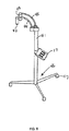
手持ち式装置と反対に、装置を独立型設定で作動させてもよい。例えば本装置を壁のような支持構造によって支えてもよいし、又は床又は診察台の上に置かれる持ち運びのできる台によって支えてもよい。この独立型装置によって筐体を動かさずにレーザービームを患者に走査することができる。図6は本発明の持ち運び可能な床に置かれる例を示す。2つの筐体42及び43は各々コネクター44及び45でアーム41と連結している。コネクターは硬くてもよいが、望ましくは筐体をあらゆる望ましい位置に動かすことができるように柔軟性があってもよい。レーザーの位置をさらに制御するためにアーム41を連結してもよい。アーム41は車輪47を持つ台46に取り付けられ、装置をあらゆる望ましい位置に移動させ、その後治療が行われている間実質的に静置させることが可能である。これは特に診察台に横になった又は車椅子に座った患者に都合がよい。制御手段17を筐体に電気的に連結し図6に示されているようにアーム41に備えつける。しかしながら前記制御手段を他の場所に備えつけることもでき、又はラジオ周波数又は当該技術分野で知られた他の方法を使用するリモートコントロールとして作動させることもできる。
As opposed to a handheld device, the device may be operated in a stand-alone setting. For example, the device may be supported by a support structure such as a wall, or may be supported by a portable platform placed on the floor or examination table. This stand-alone device allows the patient to scan the laser beam without moving the housing. FIG. 6 shows an example placed on the portable floor of the present invention. The two
図8は壁に備えつけたアーム51に取り付けられた3つの筐体アセンブリ50を示す。アーム51は、あらゆる望ましい位置に動き、その後治療が行われている間実質的に静置することができるように当該技術分野において知られている方法で壁52に取り付けられている。アームがレーザーの位置をさらに制御するために連結していてもよい。制御手段17は筐体に電気的に連結し図10に示されているように壁に備えつけられる。しかしながら前記制御手段は他の場所に備えつけることもでき、又はラジオ周波数又は当該技術分野で知られた他の方法を使用するリモートコントロールとして作動させることもできる。アセンブリ50はそれがあらゆる望ましい位置に移動させることができるように当該技術分野で周知の方法でアーム51に取り付けられている。同様に筐体53、54、55は前記アセンブリに取り付けられているので各々を望ましい位置に移動させることができる。
FIG. 8 shows three
レーザー光が望ましくない位置に反射又は屈折するのを妨げるために遮蔽物が使用されてもよい。図8参照。前記遮蔽物は放射線を遮断する適切な場所に取り付けられる。例えば、遮蔽物61はアセンブリに取り付けられていてもよく、1もしくはそれ以上の筐体に取り付けられてもよいし、患者に着用されてもよい。図11は患者の頭で反射又は屈折する可能性のあるレーザー光を遮断する遮蔽物61を図示する。それは天蓋またはヘルメットのような形状であり望ましくはアセンブリ50に取り付けられレーザー光が天蓋から逃げないように筐体53、54、55は遮蔽物61を貫通する。遮蔽物は遮蔽する場所に合うように他の形状を取ってもよい。例えば、遮蔽物は患者の上体幹を遮蔽するため長方形又は半円柱形でもよい。
A shield may be used to prevent the laser light from reflecting or refracting to undesired locations. See FIG. The shield is attached to a suitable location that blocks radiation. For example, the shield 61 may be attached to the assembly, may be attached to one or more housings, and may be worn by the patient. FIG. 11 illustrates a shield 61 that blocks laser light that may be reflected or refracted by the patient's head. It is shaped like a canopy or helmet and is preferably attached to the
図8は育毛のための低レベルレーザー放射の用途を図示する。患者71は薄毛でありレーザーアセンブリ50を彼の頭上に配置する。治療中患者は楽に座ったままでいてもよく又は診察台上に横になっていてもよく、患者を治療するのに治療者の介入は必要ない。望ましい実施形態において、制御手段17によって各筐体53、54、55の方向を定め、患者の頭皮への望ましいレーザー出力とともに望ましい各走査パターン73、74、75を伝達する。前記レーザー光の性質のため、前記患者のいかなる存在している髪を通して治療することが可能で、そのため髪又は頭皮に接触してレーザーのための軌道から髪を取り除く必要はない。
FIG. 8 illustrates the use of low level laser radiation for hair growth.
最も低レベルのレーザー治療は約630nmと約670nmの間のスペクトルの赤色領域の単一波長において有効であることが証明されている。しかしながらLLLTは可視光、近赤外線、近紫外線領域を通して有効でありうることが示されている。レーザーダイオードは利用できるスペクトルのある限られた部分だけしか網羅していないものが現在利用可能であるので、他のレーザーエネルギー源が使用される。最大の利益を得るため2もしくはそれ以上の異なる波長にて患者を刺激することが望ましい。当業者は低レベルレーザー治療に使用するための様々なレーザーエネルギー源が当該技術分野で周知であるということに気付くであろう。それらは632nm波長を持つヘリウム−ネオンレーザー及び600〜800nmの間の広範囲の波長を持つ半導体ダイオードレーザーを含む。望ましい実施形態におけるレーザーエネルギー源は半導体レーザーダイオードであり、それは可視光スペクトルの赤色範囲の光をつくり、約635nmの波長を持つ。他の適した波長は他の特定の応用に対して使用される。望ましい実施形態は単一レーザーエネルギー源11を持つものとして記載されるが、2もしくはそれ以上のレーザーエネルギー源を持ってもよいだろう。これらのレーザー源はレーザーアセンブリの中にてお互いに接していてもよいし個々に支持構造についていてもよい。多数のLLLTのレジメンが紫外線または赤外線レーザー光を含む一方で、可視光のエネルギースペクトルの少なくとも1つのレーザービームを使用することは好都合であり、結果として操作者はレーザー光を見ることができ、それを作用させる時治療される患者の体及び範囲が簡単に規定できる。
The lowest level of laser treatment has proven effective at a single wavelength in the red region of the spectrum between about 630 nm and about 670 nm. However, it has been shown that LLLT can be effective through the visible, near infrared, and near ultraviolet regions. Other laser energy sources are used because laser diodes are currently available that cover only a limited portion of the available spectrum. It is desirable to stimulate the patient at two or more different wavelengths for maximum benefit. Those skilled in the art will be aware that various laser energy sources for use in low level laser therapy are well known in the art. They include helium-neon lasers with a wavelength of 632 nm and semiconductor diode lasers with a wide range of wavelengths between 600 and 800 nm. The laser energy source in the preferred embodiment is a semiconductor laser diode, which produces light in the red range of the visible light spectrum and has a wavelength of about 635 nm. Other suitable wavelengths are used for other specific applications. Although the preferred embodiment is described as having a single
異なる治療レジメンは異なるワットのダイオードを必要とする。望ましいレーザーダイオードは各電源の1ワット以下を使用し同時に脂肪吸引を促進し、術後炎症や術後疼痛を治療し、同様に毛髪を回復させる。様々な他のワット数のダイオードをまたあるレジメンに望ましいレーザーエネルギーを得るのに使用してもよい。本発明の利点はより高い電源のレーザーを必要とせずにより大きな治療範囲を得ることができるということである。 Different treatment regimens require different watt diodes. The preferred laser diode uses less than 1 watt of each power source to simultaneously promote liposuction, treat post-operative inflammation and post-operative pain, and restore hair as well. A variety of other wattage diodes may also be used to obtain the desired laser energy for a given regimen. An advantage of the present invention is that a larger therapeutic range can be obtained without the need for a higher power laser.
レーザー制御13は、望ましくは制御手段17に組み入れられ、放射するレーザー光の各パルスの持続時間及びパルス周波数を制御する。パルスがない時、レーザー光の連続したビームが発生する。0から100,000Hzもしくはそれ以上のパルス周波数を患者組織に対する望ましい効果を得るのに使用してもよい。LLLTレジメンの目標は、短いが十分に標的組織に電圧を加え周辺の組織には熱による損傷を与えないパルス幅を使用してレーザーエネルギーを標的組織に運ぶことである。
本発明の望ましい実施形態であると現在考えられているものを図示し記載したが、本発明の要旨の範囲を越えることなく様々な変化と改良がなされてもよく同等のものが関連要素の代替になってもよいことが当業者に理解されるだろう。したがって本発明は本発明を実施するために熟慮された最良の様式として開示された特定の実施形態に制限されるものではなく、しかし本発明は補正された請求項の範囲に入る全ての実施形態を含むものである。 While what is presently considered to be a preferred embodiment of the invention has been illustrated and described, various changes and modifications may be made without departing from the scope of the invention, and equivalents may be substituted for related elements. It will be appreciated by those skilled in the art that Accordingly, the invention is not limited to the specific embodiments disclosed as the best mode contemplated for practicing the invention, but the invention is construed as all embodiments falling within the scope of the amended claims. Is included.
Claims (15)
a)走査ヘッドを有し、この走査ヘッドは、
i)前記レーザービームと実質的に同軸上にある中空スピンドルであって、前記レーザービームが当該中空スピンドル内を通って伝達されるものである、前記中空スピンドルと、
ii)前記レーザービームが入射する屈折性光学素子であって、前記レーザービームが当該光学素子を通過して伝達されることにより、前記中空スピンドルの軸の延長線上に中心点を有する線形ビームスポットが生成されるものである、前記光学素子と、
iii)前記光学素子を保持する回転自在なキャリッジとを有し、
前記キャリッジが前記光学素子を回転させると、前記線形ビームスポットは、当該線形ビームスポットを直径とする円形状のビームスポットを掃引するものである
レーザー装置。A laser device having at least one laser energy source for generating a laser beam, the laser device comprising:
a) having a scanning head, the scanning head comprising:
i) a hollow spindle substantially coaxial with the laser beam, wherein the laser beam is transmitted through the hollow spindle;
ii) a refractive optical element on which the laser beam is incident, and the laser beam is transmitted through the optical element so that a linear beam spot having a center point on an extension line of the axis of the hollow spindle is formed. The optical element to be generated;
iii) and a rotatable carriage for holding the optical element,
When the carriage rotates the optical element, the linear beam spot sweeps a circular beam spot having the diameter of the linear beam spot .
a)主駆動ギア
b)副駆動ギア
c)前記主駆動ギアを前記副駆動ギアに協働させ前記キャリッジを回転させるモーターを有するものであるレーザー装置。5. The laser device according to claim 4 , wherein the drive assembly further includes a) a main drive gear, b) a sub drive gear, c) a motor for rotating the carriage by cooperating the main drive gear with the sub drive gear. A laser device .
Applications Claiming Priority (3)
| Application Number | Priority Date | Filing Date | Title |
|---|---|---|---|
| US11/409,408 | 2006-04-20 | ||
| US11/409,408 US7947067B2 (en) | 2004-02-04 | 2006-04-20 | Scanning treatment laser with sweep beam spot and universal carriage |
| PCT/US2007/009609 WO2007124021A2 (en) | 2006-04-20 | 2007-04-20 | Scanning treatment laser with sweep beam spot and universal carriage |
Publications (2)
| Publication Number | Publication Date |
|---|---|
| JP2009534102A JP2009534102A (en) | 2009-09-24 |
| JP4976485B2 true JP4976485B2 (en) | 2012-07-18 |
Family
ID=38625599
Family Applications (1)
| Application Number | Title | Priority Date | Filing Date |
|---|---|---|---|
| JP2009506591A Active JP4976485B2 (en) | 2006-04-20 | 2007-04-20 | Scanning treatment laser with swept beam spot and universal carriage |
Country Status (10)
| Country | Link |
|---|---|
| US (1) | US7947067B2 (en) |
| EP (1) | EP2010286B1 (en) |
| JP (1) | JP4976485B2 (en) |
| KR (1) | KR101154118B1 (en) |
| CN (1) | CN101443078B (en) |
| BR (1) | BRPI0710815B8 (en) |
| CA (1) | CA2649437C (en) |
| IL (1) | IL194666A (en) |
| MX (1) | MX2008013358A (en) |
| WO (1) | WO2007124021A2 (en) |
Families Citing this family (18)
| Publication number | Priority date | Publication date | Assignee | Title |
|---|---|---|---|---|
| US20110213446A1 (en) * | 2001-03-02 | 2011-09-01 | Erchonia Corporation | Fungal Infection Therapy with Low Level Laser |
| US8790382B2 (en) | 2009-08-04 | 2014-07-29 | Yonatan Gerlitz | Handheld low-level laser therapy apparatus |
| US9553422B2 (en) | 2009-08-04 | 2017-01-24 | Medical Coherence Llc | Multiple aperture hand-held laser therapy apparatus |
| US20150005854A1 (en) * | 2013-06-27 | 2015-01-01 | Hamid Tamim Said | Portable light hair restoration helmet |
| JP2013517037A (en) * | 2010-01-14 | 2013-05-16 | ミハエル・シュローサー | Scanning mechanism and treatment method for LLLT or other light source treatment |
| US9606003B2 (en) | 2012-03-28 | 2017-03-28 | Yonatan Gerlitz | Clinical hand-held infrared thermometer with special optical configuration |
| US11583462B2 (en) | 2013-03-12 | 2023-02-21 | Biolase, Inc. | Dental laser unit with communication link to assistance center |
| KR101505083B1 (en) * | 2013-04-11 | 2015-03-25 | 한국전기연구원 | Medical handpiece able to irradiate line laser beam |
| US9946082B2 (en) | 2013-04-30 | 2018-04-17 | Medical Coherence Llc | Handheld, low-level laser apparatuses and methods for low-level laser beam production |
| KR101589579B1 (en) * | 2013-07-23 | 2016-01-28 | 한국전기연구원 | Medical handpiece able to irradiate line beam |
| WO2015103422A1 (en) | 2013-12-31 | 2015-07-09 | Biolase, Inc. | Dual wavelength laser treatment device |
| KR101437540B1 (en) * | 2014-03-31 | 2014-09-05 | (주)라메디텍 | Multi-function laser irradiating apparatus |
| EP3005969B1 (en) * | 2014-10-08 | 2023-07-19 | Bios S.r.l. | Laser device for dermo cosmetic treatments |
| CN105596081B (en) * | 2014-11-15 | 2019-12-06 | 江苏欧莱美激光科技有限公司 | Handheld precise scanning laser beauty equipment |
| US11813476B1 (en) * | 2016-12-16 | 2023-11-14 | Erchonia Corporation, Llc | Methods of treating the brain and nervous system using light therapy |
| US11446513B2 (en) | 2016-12-16 | 2022-09-20 | Erchonia Corporation, Llc | Methods of treating autism using light therapy |
| US10857378B2 (en) * | 2018-08-16 | 2020-12-08 | Erchonia Corporation, Llc | Hand-held laser treatment device with automatic sweep and adjustable sweep amplitude |
| WO2023220248A1 (en) * | 2022-05-13 | 2023-11-16 | Cold Laser Therapeutics, Llc | Switchable low pulse rate and high pulse rate laser driver |
Family Cites Families (72)
| Publication number | Priority date | Publication date | Assignee | Title |
|---|---|---|---|---|
| US2987960A (en) * | 1958-02-17 | 1961-06-13 | Bausch & Lomb | Optical system for endoscopes and the like |
| US3023662A (en) * | 1958-08-22 | 1962-03-06 | Jr Harry F Hicks | Hemispherical scanning system |
| US3653384A (en) * | 1970-10-13 | 1972-04-04 | American Optical Corp | Apparatus for directing a light beam |
| US3996319A (en) * | 1972-02-03 | 1976-12-07 | Nukem G.M.B.H. | Process for the production of pressed block fuel elements of high power for gas cooled high temperature reactor |
| US3774162A (en) * | 1972-03-01 | 1973-11-20 | Magnaflux Corp | Laser scan testing system having pattern recognition means |
| US4001840A (en) * | 1974-10-07 | 1977-01-04 | Precision Instrument Co. | Non-photographic, digital laser image recording |
| US3966319A (en) | 1975-04-21 | 1976-06-29 | Xerox Corporation | Flat field scanning mirror |
| US4176925A (en) * | 1978-06-07 | 1979-12-04 | Gte Laboratories Incorporated | Laser scanner for photolithography of slotted mask color cathode ray tubes |
| IT1171078B (en) | 1983-07-04 | 1987-06-10 | Adriano Tessiore | ELECTROMECHANICAL IRRADIANT EQUIPMENT, FOR THE TREATMENT OF HAIR LEATHER, AGAINST Baldness |
| US4729372A (en) * | 1983-11-17 | 1988-03-08 | Lri L.P. | Apparatus for performing ophthalmic laser surgery |
| IL75998A0 (en) * | 1984-08-07 | 1985-12-31 | Medical Laser Research & Dev C | Laser system for providing target tissue specific energy deposition |
| US5336217A (en) * | 1986-04-24 | 1994-08-09 | Institut National De La Sante Et De La Recherche Medicale (Insepm) | Process for treatment by irradiating an area of a body, and treatment apparatus usable in dermatology for the treatment of cutaneous angio dysplasias |
| US4767930A (en) * | 1987-03-31 | 1988-08-30 | Siemens Medical Laboratories, Inc. | Method and apparatus for enlarging a charged particle beam |
| US4965672A (en) * | 1987-05-11 | 1990-10-23 | The Mead Corporation | Method and apparatus for halftone imaging |
| FR2617042B1 (en) * | 1987-06-25 | 1994-05-13 | Hanna Khalil | CORNEAL SURGERY DEVICE |
| US5284477A (en) * | 1987-06-25 | 1994-02-08 | International Business Machines Corporation | Device for correcting the shape of an object by laser treatment |
| DE3805642C1 (en) * | 1988-02-24 | 1989-06-01 | Messerschmitt-Boelkow-Blohm Gmbh, 8012 Ottobrunn, De | |
| US5152759A (en) * | 1989-06-07 | 1992-10-06 | University Of Miami, School Of Medicine, Dept. Of Ophthalmology | Noncontact laser microsurgical apparatus |
| FR2656430B1 (en) * | 1989-12-26 | 1994-01-21 | Telecommunications Sa | SCANNING DEVICE AND ITS APPLICATION TO ANALYSIS DEVICES. |
| US5095386A (en) * | 1990-05-01 | 1992-03-10 | Charles Lescrenier | Optical system for generating lines of light using crossed cylindrical lenses |
| JP2740687B2 (en) * | 1990-06-08 | 1998-04-15 | 株式会社日本自動車部品総合研究所 | Optical scanning device |
| WO1992003187A1 (en) | 1990-08-22 | 1992-03-05 | Phoenix Laser Systems, Inc. | System for scanning a surgical laser beam |
| US5422471A (en) * | 1991-08-16 | 1995-06-06 | Plesko; George A. | Scanning device for scanning a target, scanning motor for the device and a method of utilization thereof |
| US5461473A (en) * | 1990-12-31 | 1995-10-24 | Spatial Positioning Systems, Inc. | Transmitter and receiver units for spatial position measurement system |
| WO1993021993A1 (en) | 1992-04-24 | 1993-11-11 | Kim Robin Segal | Low level laser for soft tissue treatment |
| US5268554A (en) * | 1992-06-29 | 1993-12-07 | General Electric Co. | Apparatus and system for positioning a laser beam |
| US5413555A (en) * | 1993-04-30 | 1995-05-09 | Mcmahan; William H. | Laser delivery system |
| CO4230054A1 (en) * | 1993-05-07 | 1995-10-19 | Visx Inc | METHOD AND SYSTEMS FOR LASER TREATMENT OF REFRACTIVE ERRORS USING TRAVELING IMAGES FORMATION |
| US5860967A (en) * | 1993-07-21 | 1999-01-19 | Lucid, Inc. | Dermatological laser treatment system with electronic visualization of the area being treated |
| JP3040643B2 (en) * | 1993-09-02 | 2000-05-15 | シャープ株式会社 | Optical scanning device |
| US5743902A (en) * | 1995-01-23 | 1998-04-28 | Coherent, Inc. | Hand-held laser scanner |
| DE29508077U1 (en) * | 1995-05-16 | 1995-08-10 | Wilden Lutz Dr Med | Oral care device |
| US5879376A (en) * | 1995-07-12 | 1999-03-09 | Luxar Corporation | Method and apparatus for dermatology treatment |
| US5860968A (en) * | 1995-11-03 | 1999-01-19 | Luxar Corporation | Laser scanning method and apparatus |
| US5630811A (en) | 1996-03-25 | 1997-05-20 | Miller; Iain D. | Method and apparatus for hair removal |
| US6013096A (en) * | 1996-11-22 | 2000-01-11 | Tucek; Kevin B. | Hand-held laser light generator device |
| US6273884B1 (en) * | 1997-05-15 | 2001-08-14 | Palomar Medical Technologies, Inc. | Method and apparatus for dermatology treatment |
| DE19725877B4 (en) | 1997-06-18 | 2004-02-05 | Fraunhofer-Gesellschaft zur Förderung der angewandten Forschung e.V. | Application device for removing biological tissue |
| SE510410C2 (en) | 1997-07-07 | 1999-05-17 | Laser Science Ab | Electromagnetic radiation device for treating scalp to promote hair growth |
| US6168590B1 (en) * | 1997-08-12 | 2001-01-02 | Y-Beam Technologies, Inc. | Method for permanent hair removal |
| JPH1170121A (en) * | 1997-08-29 | 1999-03-16 | Nidek Co Ltd | Laser treatment device |
| US6074382A (en) * | 1997-08-29 | 2000-06-13 | Asah Medico A/S | Apparatus for tissue treatment |
| US5968033A (en) * | 1997-11-03 | 1999-10-19 | Fuller Research Corporation | Optical delivery system and method for subsurface tissue irradiation |
| US6165170A (en) * | 1998-01-29 | 2000-12-26 | International Business Machines Corporation | Laser dermablator and dermablation |
| US6185030B1 (en) * | 1998-03-20 | 2001-02-06 | James W. Overbeck | Wide field of view and high speed scanning microscopy |
| US6149643A (en) * | 1998-09-04 | 2000-11-21 | Sunrise Technologies International, Inc. | Method and apparatus for exposing a human eye to a controlled pattern of radiation |
| US6208673B1 (en) * | 1999-02-23 | 2001-03-27 | Aculight Corporation | Multifunction solid state laser system |
| US6900916B2 (en) * | 1999-03-04 | 2005-05-31 | Fuji Photo Film Co., Ltd. | Color laser display apparatus having fluorescent screen scanned with modulated ultraviolet laser light |
| US6312451B1 (en) * | 1999-03-23 | 2001-11-06 | Jackson Streeter | Low level laser therapy apparatus |
| US6267779B1 (en) * | 1999-03-29 | 2001-07-31 | Medelaser, Llc | Method and apparatus for therapeutic laser treatment |
| WO2000071045A1 (en) * | 1999-05-25 | 2000-11-30 | International Technologies (Lasers), Ltd. | Laser for skin treatment |
| DE29916584U1 (en) | 1999-09-21 | 2000-05-04 | Laser & Med Tech Gmbh | Swash optics for high-performance light sources |
| TW478032B (en) * | 1999-11-04 | 2002-03-01 | Seiko Epson Corp | Method and device for laser plotting, hologram master and the manufacturing method thereof |
| JP2002000745A (en) * | 2000-06-16 | 2002-01-08 | Nidek Co Ltd | Laser therapeutic device |
| JP2002011106A (en) * | 2000-06-28 | 2002-01-15 | Nidek Co Ltd | Laser therapeutic apparatus |
| US7012696B2 (en) * | 2000-07-12 | 2006-03-14 | Macquarie Research Ltd. | Optical heterodyne detection in optical cavity ringdown spectroscopy |
| US7918846B2 (en) * | 2000-12-05 | 2011-04-05 | Amo Manufacturing Usa, Llc | Method and system for laser treatment of refractive errors using offset imaging |
| US6626834B2 (en) * | 2001-01-25 | 2003-09-30 | Shane Dunne | Spiral scanner with electronic control |
| ITTO20010102A1 (en) * | 2001-02-05 | 2002-08-05 | Prima Ind Spa | REMOTE LASER WELDING SYSTEM AND METHOD. |
| DE10108655A1 (en) * | 2001-02-22 | 2002-09-26 | W & H Dentalwerk Buermoos Ges | Medical laser treatment device |
| US6746473B2 (en) * | 2001-03-02 | 2004-06-08 | Erchonia Patent Holdings, Llc | Therapeutic laser device |
| US6497719B2 (en) * | 2001-03-06 | 2002-12-24 | Henry Pearl | Apparatus and method for stimulating hair growth |
| US20020138071A1 (en) * | 2001-03-22 | 2002-09-26 | Angeley David G. | Scanning laser handpiece with shaped output beam |
| US6887233B2 (en) * | 2001-03-22 | 2005-05-03 | Lumenis, Inc. | Scanning laser handpiece with shaped output beam |
| US6666878B2 (en) * | 2001-06-06 | 2003-12-23 | Inca Asset Management S.A. | Method and device stimulating the activity of hair follicles |
| US7187445B2 (en) * | 2001-07-19 | 2007-03-06 | Automotive Distance Control Systems Gmbh | Method and apparatus for optically scanning a scene |
| HU224941B1 (en) * | 2001-08-10 | 2006-04-28 | Bgi Innovacios Kft | Phototerapy apparatus |
| JP2003174922A (en) * | 2001-12-11 | 2003-06-24 | Products:Kk | Hair removal method using light energy |
| JP3905393B2 (en) * | 2002-02-07 | 2007-04-18 | オリンパス株式会社 | Surgical device |
| US7120482B2 (en) * | 2002-11-18 | 2006-10-10 | Honda Motor Co., Ltd. | Optical measuring apparatus and method |
| CN2588326Y (en) * | 2002-12-27 | 2003-11-26 | 南京泉峰国际贸易有限公司 | Laser line marking device |
| US20060070251A1 (en) * | 2003-11-12 | 2006-04-06 | Shuming Wu | Line-marking device with rotatable laser |
-
2006
- 2006-04-20 US US11/409,408 patent/US7947067B2/en active Active
-
2007
- 2007-04-20 JP JP2009506591A patent/JP4976485B2/en active Active
- 2007-04-20 EP EP07755760A patent/EP2010286B1/en active Active
- 2007-04-20 MX MX2008013358A patent/MX2008013358A/en active IP Right Grant
- 2007-04-20 WO PCT/US2007/009609 patent/WO2007124021A2/en active Search and Examination
- 2007-04-20 BR BRPI0710815A patent/BRPI0710815B8/en active IP Right Grant
- 2007-04-20 CA CA2649437A patent/CA2649437C/en active Active
- 2007-04-20 KR KR1020087026217A patent/KR101154118B1/en active IP Right Review Request
- 2007-04-20 CN CN200780013964.8A patent/CN101443078B/en active Active
-
2008
- 2008-10-12 IL IL194666A patent/IL194666A/en active IP Right Grant
Also Published As
| Publication number | Publication date |
|---|---|
| EP2010286B1 (en) | 2011-10-26 |
| KR20090005072A (en) | 2009-01-12 |
| BRPI0710815A2 (en) | 2011-08-23 |
| MX2008013358A (en) | 2009-01-19 |
| US7947067B2 (en) | 2011-05-24 |
| CA2649437C (en) | 2013-02-19 |
| IL194666A (en) | 2014-03-31 |
| KR101154118B1 (en) | 2012-06-11 |
| BRPI0710815B1 (en) | 2019-04-02 |
| WO2007124021A3 (en) | 2008-03-20 |
| IL194666A0 (en) | 2009-08-03 |
| CN101443078B (en) | 2015-05-27 |
| CN101443078A (en) | 2009-05-27 |
| EP2010286A2 (en) | 2009-01-07 |
| WO2007124021A2 (en) | 2007-11-01 |
| JP2009534102A (en) | 2009-09-24 |
| BRPI0710815B8 (en) | 2021-06-22 |
| US20060224218A1 (en) | 2006-10-05 |
| CA2649437A1 (en) | 2007-11-01 |
Similar Documents
| Publication | Publication Date | Title |
|---|---|---|
| JP4976485B2 (en) | Scanning treatment laser with swept beam spot and universal carriage | |
| US8097029B2 (en) | Stand-alone scanning laser device | |
| JP4194940B2 (en) | Improved handheld laser system | |
| US8439927B2 (en) | Method of using a multi-probe laser device | |
| US8814924B2 (en) | Fungal infection therapy device with low level laser | |
| US7118588B2 (en) | Scanning treatment laser | |
| US8409264B2 (en) | Fungal infection therapy method with low level laser | |
| EP2523728B1 (en) | Scanning mechanism for lllt or other light source therapy |
Legal Events
| Date | Code | Title | Description |
|---|---|---|---|
| A131 | Notification of reasons for refusal |
Free format text: JAPANESE INTERMEDIATE CODE: A131 Effective date: 20110913 |
|
| A977 | Report on retrieval |
Free format text: JAPANESE INTERMEDIATE CODE: A971007 Effective date: 20110915 |
|
| A601 | Written request for extension of time |
Free format text: JAPANESE INTERMEDIATE CODE: A601 Effective date: 20111213 |
|
| A602 | Written permission of extension of time |
Free format text: JAPANESE INTERMEDIATE CODE: A602 Effective date: 20111220 |
|
| A601 | Written request for extension of time |
Free format text: JAPANESE INTERMEDIATE CODE: A601 Effective date: 20120110 |
|
| A602 | Written permission of extension of time |
Free format text: JAPANESE INTERMEDIATE CODE: A602 Effective date: 20120117 |
|
| A521 | Request for written amendment filed |
Free format text: JAPANESE INTERMEDIATE CODE: A523 Effective date: 20120201 |
|
| TRDD | Decision of grant or rejection written | ||
| A01 | Written decision to grant a patent or to grant a registration (utility model) |
Free format text: JAPANESE INTERMEDIATE CODE: A01 Effective date: 20120313 |
|
| A01 | Written decision to grant a patent or to grant a registration (utility model) |
Free format text: JAPANESE INTERMEDIATE CODE: A01 |
|
| A61 | First payment of annual fees (during grant procedure) |
Free format text: JAPANESE INTERMEDIATE CODE: A61 Effective date: 20120412 |
|
| R150 | Certificate of patent or registration of utility model |
Ref document number: 4976485 Country of ref document: JP Free format text: JAPANESE INTERMEDIATE CODE: R150 Free format text: JAPANESE INTERMEDIATE CODE: R150 |
|
| FPAY | Renewal fee payment (event date is renewal date of database) |
Free format text: PAYMENT UNTIL: 20150420 Year of fee payment: 3 |
|
| R250 | Receipt of annual fees |
Free format text: JAPANESE INTERMEDIATE CODE: R250 |
|
| R250 | Receipt of annual fees |
Free format text: JAPANESE INTERMEDIATE CODE: R250 |
|
| R250 | Receipt of annual fees |
Free format text: JAPANESE INTERMEDIATE CODE: R250 |
|
| R250 | Receipt of annual fees |
Free format text: JAPANESE INTERMEDIATE CODE: R250 |
|
| R250 | Receipt of annual fees |
Free format text: JAPANESE INTERMEDIATE CODE: R250 |
|
| R250 | Receipt of annual fees |
Free format text: JAPANESE INTERMEDIATE CODE: R250 |