JP4976189B2 - Grout injection tool - Google Patents
Grout injection tool Download PDFInfo
- Publication number
- JP4976189B2 JP4976189B2 JP2007109437A JP2007109437A JP4976189B2 JP 4976189 B2 JP4976189 B2 JP 4976189B2 JP 2007109437 A JP2007109437 A JP 2007109437A JP 2007109437 A JP2007109437 A JP 2007109437A JP 4976189 B2 JP4976189 B2 JP 4976189B2
- Authority
- JP
- Japan
- Prior art keywords
- cylindrical shaft
- shaft portion
- mounting seat
- injection
- sealing material
- Prior art date
- Legal status (The legal status is an assumption and is not a legal conclusion. Google has not performed a legal analysis and makes no representation as to the accuracy of the status listed.)
- Active
Links
- 238000002347 injection Methods 0.000 title claims description 84
- 239000007924 injection Substances 0.000 title claims description 84
- 239000011440 grout Substances 0.000 title claims description 46
- 239000003795 chemical substances by application Substances 0.000 claims description 39
- 238000003780 insertion Methods 0.000 claims description 17
- 230000037431 insertion Effects 0.000 claims description 17
- 238000001802 infusion Methods 0.000 claims 2
- 239000003566 sealing material Substances 0.000 description 41
- 238000004891 communication Methods 0.000 description 10
- 239000000463 material Substances 0.000 description 9
- 230000006835 compression Effects 0.000 description 8
- 238000007906 compression Methods 0.000 description 8
- 239000011800 void material Substances 0.000 description 7
- 210000002445 nipple Anatomy 0.000 description 6
- 229920003002 synthetic resin Polymers 0.000 description 5
- 239000000057 synthetic resin Substances 0.000 description 5
- 239000002184 metal Substances 0.000 description 3
- 238000000034 method Methods 0.000 description 2
- 239000000853 adhesive Substances 0.000 description 1
- 230000001070 adhesive effect Effects 0.000 description 1
- 238000013459 approach Methods 0.000 description 1
- 230000004323 axial length Effects 0.000 description 1
- 238000005336 cracking Methods 0.000 description 1
- 229920001971 elastomer Polymers 0.000 description 1
- 239000005060 rubber Substances 0.000 description 1
- 229920003051 synthetic elastomer Polymers 0.000 description 1
- 239000005061 synthetic rubber Substances 0.000 description 1
- XLYOFNOQVPJJNP-UHFFFAOYSA-N water Substances O XLYOFNOQVPJJNP-UHFFFAOYSA-N 0.000 description 1
Images


Landscapes
- Working Measures On Existing Buildindgs (AREA)
Description
この発明は、コンクリート構造物にシール材で取付けた状態で、コンクリート構造物に発生したクラック等の空隙にグラウト剤を注入して補修するために用いるグラウト剤の注入具に関する。 The present invention relates to a grout agent injection tool used for injecting and repairing a grout agent into a gap such as a crack generated in a concrete structure in a state where the concrete structure is attached with a sealing material.
コンクリート構造物の内部に発生したクラック等の空隙を放置すると、漏水やコンクリートの割れ、外装材として貼り付けたタイルの剥離等が発生するため、クラック等の空隙をグラウト剤の注入によって埋める必要がある。 Leaving voids such as cracks generated inside a concrete structure may cause water leakage, cracking of the concrete, peeling of tiles attached as exterior materials, etc., so it is necessary to fill the voids such as cracks by injecting a grout agent. is there.
図4(a)は、上記のようなクラック等の空隙にグラウト剤を注入するため、一般的に用いられている従来の注入具の一例とこの注入具のコンクリート構造物への取付け構造を示している。 FIG. 4 (a) shows an example of a conventional injection tool generally used for injecting a grouting agent into a gap such as a crack as described above, and a structure for attaching the injection tool to a concrete structure. ing.
上記注入具1は、グラウト剤の注入路2が軸方向に貫通する筒軸部3の後端に、逆止弁を内蔵したニップル4を取付け、前記筒軸部3の先端側の外周に、コンクリート構造物にシール材で取付ける円板状の取付け座5を設け、筒軸部3の途中に設けた分岐筒6に蓄圧タンク7を取付けた構造になっている。
The
このような注入具1を用いてコンクリート構造物Aに発生したクラック等の空隙Bを補修するには、図4(b)のように、コンクリート構造物Aの外面でクラック等の空隙Bや内部クラックと連通するように設けた穿孔を囲むようにしてシール材(接着剤)Cを塗着し、次に、注入具1の取付け座5を前記シール材Cに押し付けて変形させながら圧着させ、シール材Cの硬化によってコンクリート構造物Aに注入具1を固定する。
In order to repair the void B such as a crack generated in the concrete structure A by using such an
上記の状態で、注入具1のニップル4にグラウト剤の注入源を接続し、この注入具1を介して隙間Bにグラウト剤を注入し、グラウト剤が隙間Bを埋めた後に蓄圧タンク7内にグラウト剤が進入する量を注入し、蓄圧タンク7内の空気を加圧することでグラウト剤が圧力を蓄え、隙間Bに対して蓄圧タンク7内のグラウト剤を経時的に押し込むことで、隙間Bへのグラウト剤の注入を完全なものとし、グラウト剤の硬化後にコンクリート構造物Aから注入具1を撤去することで隙間Bの補修が完了する。
In the above-described state, a grout agent injection source is connected to the nipple 4 of the
ところで、上記のように、コンクリート構造物Aに対して注入具1を取付けるに際して、コンクリート構造物Aの外面でクラック等の空隙Bや穿孔を囲むように塗布したシール材Cに、注入具1の取付け座5を押し付けて変形させながら圧着させると、圧縮を受けて変形したシール材Cは取付け座5の面方向に移動するため、内側に向けて移動したシール材Cが図4(c)のように空隙Bや穿孔を覆うことになり、このため、空隙Bや穿孔の開口部分がシール材Cで塞がれ、筒軸部3の注入路2と空隙Bや穿孔の連通が遮断され、注入具1からを空隙Bや穿孔にグラウト剤を充填することができない事態が発生するという問題がある。
By the way, when the
そこで、この発明の課題は、コンクリート構造物に対する注入具の固定時に、空隙や穿孔の開口部分をシール材で塞ぐようなことがなく、筒軸部の注入路と空隙や穿孔の連通を確保することで、空隙や穿孔にグラウト剤を確実に充填することができるグラウト剤の注入具を提供することにある。 Therefore, the object of the present invention is to secure the communication between the injection path of the cylindrical shaft portion and the gap and the perforation without closing the gap and the opening of the perforation with the sealing material when the injection tool is fixed to the concrete structure. Thus, an object of the present invention is to provide a grout agent injection tool that can reliably fill a gap or perforation with a grout agent.
上記のような課題を解決するため、請求項1の発明は、後端にグラウト剤の注入源を接続するようにした筒軸部の先端側外周に取付け座を設けたグラウト剤の注入具において、前記筒軸部の先端側に、この筒軸部の内部と連通する状態で、前記取付け座の先端面から外部に突出するように可動パイプを取付け、この可動パイプを筒軸部に対して軸方向に移動可能とした構成を採用したものである。
In order to solve the above-described problems, the invention of
上記可動パイプは、合成樹脂、ゴム、金属を用い、筒軸部に対して摩擦があり、抜き差しできる程度の外径で10mm程度の長さに形成され、注入具の取付け座をシール材に押し付けたとき、可動パイプの先端が先にコンクリート構造物に当接し、その後の注入具の押し込みを許容することで、圧縮を受けて変形したシール材が空隙や穿孔を覆うのを可動パイプで阻止することにより、筒軸部の注入路と空隙や穿孔の連通を確保することになる。 The movable pipe is made of synthetic resin, rubber, metal, and has a friction with respect to the cylindrical shaft part. The movable pipe has an outer diameter of about 10 mm and can be inserted and removed. The mounting seat of the injection tool is pressed against the sealing material. When the tip of the movable pipe comes into contact with the concrete structure first, and then allows the injection tool to be pushed in, the movable pipe prevents the deformed seal material from covering the gap and the perforation with compression. As a result, communication between the injection path of the cylindrical shaft portion and the gap or perforation is ensured.
請求項2の発明は、後端にグラウト剤の注入源を接続するようにした筒軸部の先端側外周に取付け座を設けたグラウト剤の注入具において、前記筒軸部の先端側と取付け座の連接部分で取付け座の先端面側に、前記筒軸部と同軸芯となる延長筒軸を囲むようにして環状の凹溝を設け、前記延長筒軸の先端を取付け座の先端面よりも外部に突出させた構成を採用したものである。 According to a second aspect of the present invention, there is provided a grout injection device provided with a mounting seat on the outer periphery of the front end side of the cylindrical shaft portion connected to the rear end of the injection source of the grout agent. An annular groove is provided on the distal end side of the mounting seat at the connecting portion of the seat so as to surround the extended cylindrical shaft that is coaxial with the cylindrical shaft portion, and the distal end of the extended cylindrical shaft is located outside the distal end surface of the mounting seat. This is a structure that protrudes from the top.
上記注入具の取付け座をシール材に押し付けたとき、押し込み途中は取付け座の中央に延長筒軸が位置してその周囲に凹溝があるので、圧縮を受けて変形したシール材が凹溝内に収まり、延長筒軸の先端がコンクリート構造物に当接して押し込み完了時には、延長筒軸が圧縮を受けて変形したシール材が空隙や穿孔を覆うのを阻止することにより、筒軸部の注入路と空隙や穿孔の連通を確保することになる。 When the mounting seat of the injection device is pressed against the sealing material, the extension cylinder shaft is located in the center of the mounting seat and there is a concave groove around it. When the end of the extension cylinder shaft comes into contact with the concrete structure and is pushed in, the extension cylinder shaft is compressed to prevent the deformed seal material from covering the gaps and perforations, thereby injecting the cylinder shaft portion. This will ensure communication between the road and the gap or perforation.
ここで、請求項1と2における注入具の構造としては、後端にニップルを取付けたり円錐面にした筒軸部の先端に円形板状の取付け座を設け、筒軸部の途中に蓄圧タンクを設けたタイプと、後端にニップルを取付けた筒軸部の先端に円形板状の取付け座を設けたタイプと、後端が開放した筒軸部の先端に円形板状の取付け座を設けたタイプを例示することができる。
Here, as the structure of the injection tool in
請求項3の発明は、後端にグラウト剤の注入源を接続するようにした筒軸部の先端側外周に取付け座を設けたグラウト剤の注入具において、前記筒軸部の後端が開放された構造となり、この筒軸部の内部に後端側から抜き差し自在に挿入する差込みパイプを別体に備え、この差込みパイプの軸方向の長さを筒軸部よりも長尺とした構成を採用したものである。 According to a third aspect of the present invention, there is provided a grout agent injecting device in which a mounting seat is provided on the outer periphery on the front end side of the cylindrical shaft portion, wherein a grout agent injection source is connected to the rear end, and the rear end of the cylindrical shaft portion is opened. The structure is such that a separate insertion pipe is inserted into the cylindrical shaft portion from the rear end side so that it can be freely inserted and removed, and the axial length of the insertion pipe is longer than the cylindrical shaft portion. Adopted.
上記注入具の筒軸部に差込みパイプを挿入しておき、注入具の取付け座をシール材に押し付けるとき、先に差込みパイプの先端をコンクリート構造物に当接させた状態で、注入具を押し込むようにすればよく、圧縮を受けて変形したシール材が空隙や穿孔を覆うのを差込みパイプで阻止することにより、筒軸部の注入路と空隙や穿孔の連通を確保することになり、この後、差込みパイプを抜き取ればよい。 When the insertion pipe is inserted into the cylindrical shaft portion of the injection tool and the mounting seat of the injection tool is pressed against the sealing material, the injection tool is pushed in with the tip of the insertion pipe being in contact with the concrete structure first. In this case, the plug material prevents the sealing material deformed by compression from covering the gaps and the perforations, thereby ensuring communication between the injection path of the cylindrical shaft portion and the gaps and the perforations. Then, the insertion pipe can be removed.
請求項1の発明によると、注入具における筒軸部の先端側に、この筒軸部の内部と連通する状態で、前記取付け座の先端面から外部に突出するように可動パイプを取付け、この可動パイプを筒軸部に対して軸方向に移動可能としたので、注入具の取付け座をシール材に押し付けたとき、可動パイプの先端が先にコンクリート構造物に当接し、その後の注入具の押し込みを許容することで、圧縮を受けて変形したシール材が空隙や穿孔を覆うのを可動パイプで阻止することにより、筒軸部の注入路と空隙や穿孔の連通を確保することができ、空隙や穿孔にグラウト剤を確実に充填することができる。 According to the first aspect of the present invention, the movable pipe is attached to the distal end side of the cylindrical shaft portion of the injection tool so as to protrude from the distal end surface of the mounting seat in a state communicating with the interior of the cylindrical shaft portion. Since the movable pipe is movable in the axial direction with respect to the cylindrical shaft, when the mounting seat of the injection tool is pressed against the seal material, the tip of the movable pipe comes into contact with the concrete structure first, and the subsequent injection tool By allowing the push-in, the movable pipe prevents the sealing material deformed by compression from covering the voids and perforations, thereby ensuring communication between the injection path of the cylindrical shaft portion and the voids and perforations. The grout agent can be reliably filled in the voids and perforations.
請求項2の発明によると、注入具における筒軸部の他端側と取付け座の連接部分で取付け座の先端面側に、前記筒軸部と同軸芯となる延長筒軸を囲むようにして環状の凹溝を設け、前記延長筒軸の先端を取付け座の先端面よりも外部に突出させたので、注入具の取付け座をシール材に押し付けたとき、押し込み途中は取付け座の中央に延長筒軸が位置してその周囲に凹溝があるので、圧縮を受けて変形したシール材が凹溝内に収まり、延長筒軸の先端がコンクリート構造物に当接して押し込み完了時には、延長筒軸が圧縮を受けて変形したシール材が空隙や穿孔を覆うのを阻止することにより、筒軸部の注入路と空隙や穿孔の連通を確保することができ、空隙や穿孔にグラウト剤を確実に充填することができる。
According to the invention of
請求項3の発明によると、注入具における筒軸部の後端が開放された構造となり、この筒軸部の内部に後端側から抜き差し自在に挿入する差込みパイプを別体に備え、この差込みパイプの軸方向の長さを筒軸部よりも長尺としたので、注入具の筒軸部に差込みパイプを挿入しておき、注入具の取付け座をシール材に押し付けるとき、先に差込みパイプの先端をコンクリート構造物に当接させた状態で、注入具を押し込むようにすれば、圧縮を受けて変形したシール材が空隙や穿孔を覆うのを差込みパイプで阻止することにより、筒軸部の注入路と空隙や穿孔の連通を確保することになり、空隙や穿孔にグラウト剤を確実に充填することができる。
According to the invention of
以下、この発明の実施の形態を図示例に基づいて説明する。 Hereinafter, embodiments of the present invention will be described based on illustrated examples.
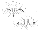
図1(a)乃至(b)に示す第1の実施の形態のグラウト剤の注入具11は、グラウト剤の注入路12が軸方向に貫通し、その後端にポンプやガン等のグラウト剤の注入源を接続するようにした筒軸部13の先端側外周に円板状の取付け座14を、例えば、合成樹脂で一体成形し、前記筒軸部13の先端側に、この筒軸部13の内部注入路12と連通する状態で、前記取付け座14の先端面から外部に突出するように可動パイプ15を取付け、この可動パイプ15を筒軸部13に対して軸方向に移動可能とした構造になっている。
The
上記可動パイプ15は、合成樹脂、ゴム、金属を用い、筒軸部13に対して摩擦があり、抜き差しできる程度の外径が10mm程度で長さも10mm程度の大きさに形成され、取付け座14の先端面から外部へ長めに突出するようにセットしておく。
The
第1の実施の形態のグラウト剤の注入具11は、上記のような構成であり、この注入具11を用いてコンクリート構造物に発生したクラック等の空隙を補修する方法を説明する。
The grout
図1(a)のように、コンクリート構造物Aの外面でクラック等の空隙Bや内部クラックと連通するように設けた穿孔を囲むようにしてシール材Cを塗着し、注入具11における筒軸部13の先端側に、可動パイプ15をこの筒軸部13の内部に、前記取付け座14の先端面から外部に突出するように取付け、注入具11の取付け座14を前記シール材Cに押し付けて変形させながら圧着させると、先ず、可動パイプ15の先端が先にコンクリート構造物Aに当接してこの可動パイプ15が空隙Bや穿孔をガードし、次に、可動パイプ15はその後の注入具11の押し込みを許容することで、シール材Cが押されて広がり、余分なシール材Cは取付け座14の外へと押し出され、内側へ移動したシール材Cは、可動パイプ15の中には進入しないので、図1(b)のように、空隙Bや穿孔がシール材Cで埋まることがない。
As shown in FIG. 1A, a sealing material C is applied so as to surround a perforation provided so as to communicate with a void B such as a crack or an internal crack on the outer surface of the concrete structure A, and a cylindrical shaft portion in the
従って、筒軸部13の注入路12と空隙Bや穿孔の連通を確保することができ、シール材Cの硬化後に注入具11を介して空隙Bにグラウト剤を注入することができる。
Therefore, it is possible to ensure communication between the
図2(a)乃至(b)に示す第2の実施の形態のグラウト剤の注入具11aは、後端にグラウト剤の注入源を接続するようにした筒軸部13の先端側外周に円板状の取付け座14を、例えば、合成樹脂で一体成形し、前記筒軸部13の先端側と取付け座14の連接部分で取付け座14の先端面側に、前記筒軸部13と同軸芯となる延長筒軸16を囲むようにして環状の凹溝17を設け、前記延長筒軸16の先端を取付け座14の先端面よりも外部に突出させた構造になっている。
The grout
上記凹溝17は、取付け座14の先端面で開口し、延長筒軸16は筒軸部13と内径が等しく、外径が筒軸部13よりも小径になっており、前記凹溝17は、開口幅が3〜10mm、最大深さが3〜8mm程度に設定され、前記延長筒軸16は、その先端が取付け座14の先端面よりも外部に0.1〜7mm程度突出している。
The
第2の実施の形態のグラウト剤の注入具11aは、上記のような構成であり、この注入具11aを用いてコンクリート構造物Aに発生したクラック等の空隙Bを補修する方法を説明する。
The
図2(a)のように、コンクリート構造物Aの外面でクラック等の空隙Bや内部クラックと連通するように設けた穿孔を囲むようにしてシール材Cを塗着し、注入具11aの取付け座14を前記シール材Cに押し付けて変形させながら圧着させると、延長筒軸16がコンクリート構造物Aに接近し、押し込み途中はシール材Cが押されて広がり、余分なシール材Cは取付け座14の外へと押し出され、内側へ移動したシール材Cは、取付け座14の中央に延長筒軸16が位置してその周囲に凹溝17があるので、圧縮を受けて内側に移動したシール材Cが凹溝17内に収まり、図2(b)のように、延長筒軸16の先端がコンクリート構造物Aに当接した押し込み完了時には、延長筒軸16が空隙Bや穿孔をガードし、圧縮を受けて内側に変形したシール材Cが空隙Bや穿孔を覆うのを阻止することにより、筒軸部13の注入路12と空隙Bや穿孔の連通を確保することができ、シール材Cの硬化後に注入具11aを介して空隙Bや穿孔にグラウト剤を確実に充填することができる。
As shown in FIG. 2A, a sealing material C is applied so as to surround a perforation provided so as to communicate with a void B such as a crack or an internal crack on the outer surface of the concrete structure A, and a mounting
なお、上記第1と第2の実施の形態の注入具11、11aは、図4(a)で示したように、後端にニップル4を取付けたり円錐面にした筒軸部の先端に円形板状の取付け座を設け、筒軸部の途中に蓄圧タンク7を設けたタイプと、後端にニップルを取付けた筒軸部の先端に円形板状の取付け座を設けたタイプと、後端が開放した筒軸部の先端に円形板状の取付け座を設けたタイプの何れであってもよい。
In addition, as shown in FIG. 4 (a), the
図3に示す第3の実施の形態のグラウト剤の注入具11bは、グラウト剤の注入源を接続する後端が開放された構造となる筒軸部13の先端側外周に取付け座14を設けて形成され、前記筒軸部13の内部注入路12に後端側から抜き差し自在に挿入する差込みパイプ18を別体に備えている。
The
上記差込みパイプ18は、金属や合成樹脂製であり、筒軸部13内に丁度嵌合する外径を有し、軸方向の長さが筒軸部13よりも長尺となっている。
The
第3の実施の形態のグラウト剤の注入具11bは、上記のような構成であり、上記注入具11bの筒軸部13に差込みパイプ18を挿入しておき、注入具11bの取付け座14をシール材Cに押し付けるとき、先に差込みパイプ18の先端をコンクリート構造物Aに当接させた状態で、注入具11bを押し込むようにすればよく、差込みパイプ18が空隙Bや穿孔をガードし、圧縮を受けて余分なシール材Cは取付け座14の外へと押し出され、差込みパイプ18は、内側へ移動したシール材Cが空隙Bや穿孔を覆うのを阻止することにより、筒軸部13の注入路12と空隙Bや穿孔の連通を確保することになり、この後、差込みパイプ18を抜き取り、シール材Cの硬化後に注入具11bを介して空隙Bや穿孔にグラウト剤を確実に充填することができる。
The
11 注入具
11a 注入具
11b 注入具
12 注入路
13 筒軸部
14 取付け座
15 可動パイプ
16 延長筒軸
17 凹溝
18 差込みパイプ
DESCRIPTION OF
Claims (2)
前記筒軸部の先端側に、この筒軸部の内部と連通する状態で、前記取付け座の先端面から外部に突出するように可動パイプを取付け、この可動パイプを筒軸部に対して軸方向に移動可能としたことを特徴とするグラウト剤の注入具。 In the grout agent infusion tool provided with a mounting seat on the outer periphery on the front end side of the cylindrical shaft portion that is configured to connect a grout agent injection source to the rear end,
A movable pipe is attached to the distal end side of the cylindrical shaft portion so as to protrude from the distal end surface of the mounting seat in a state communicating with the inside of the cylindrical shaft portion, and the movable pipe is pivoted with respect to the cylindrical shaft portion. A grout injection device characterized by being movable in the direction.
前記筒軸部の後端が開放された構造となり、この筒軸部の内部に後端側から抜き差し自在に挿入する差込みパイプを別体に備え、この差込みパイプの軸方向の長さを筒軸部よりも長尺としたことを特徴とするグラウト剤の注入具。
In the grout agent infusion tool provided with a mounting seat on the outer periphery on the front end side of the cylindrical shaft portion that is configured to connect a grout agent injection source to the rear end,
The cylindrical shaft portion has a rear end opened, and a separate insertion pipe is provided in the cylindrical shaft portion so as to be detachably inserted from the rear end side. Grouting agent injection tool characterized by being longer than the part.
Priority Applications (1)
| Application Number | Priority Date | Filing Date | Title |
|---|---|---|---|
| JP2007109437A JP4976189B2 (en) | 2007-04-18 | 2007-04-18 | Grout injection tool |
Applications Claiming Priority (1)
| Application Number | Priority Date | Filing Date | Title |
|---|---|---|---|
| JP2007109437A JP4976189B2 (en) | 2007-04-18 | 2007-04-18 | Grout injection tool |
Publications (2)
| Publication Number | Publication Date |
|---|---|
| JP2008266944A JP2008266944A (en) | 2008-11-06 |
| JP4976189B2 true JP4976189B2 (en) | 2012-07-18 |
Family
ID=40046797
Family Applications (1)
| Application Number | Title | Priority Date | Filing Date |
|---|---|---|---|
| JP2007109437A Active JP4976189B2 (en) | 2007-04-18 | 2007-04-18 | Grout injection tool |
Country Status (1)
| Country | Link |
|---|---|
| JP (1) | JP4976189B2 (en) |
Families Citing this family (4)
| Publication number | Priority date | Publication date | Assignee | Title |
|---|---|---|---|---|
| US8320191B2 (en) | 2007-08-30 | 2012-11-27 | Infineon Technologies Ag | Memory cell arrangement, method for controlling a memory cell, memory array and electronic device |
| CN101736910B (en) * | 2009-12-05 | 2011-04-13 | 西南科技大学 | Wall crack slurry pouring device |
| KR101139608B1 (en) | 2011-09-26 | 2012-04-27 | 덕주건설(주) | Structure crack conservation method using auto pressure device |
| JP7090360B1 (en) | 2021-04-23 | 2022-06-24 | 株式会社Gsc | Water stop device |
Family Cites Families (2)
| Publication number | Priority date | Publication date | Assignee | Title |
|---|---|---|---|---|
| JPH0346109Y2 (en) * | 1985-12-28 | 1991-09-30 | ||
| JP2001107571A (en) * | 1999-10-05 | 2001-04-17 | Inax Corp | Wall repair tool |
-
2007
- 2007-04-18 JP JP2007109437A patent/JP4976189B2/en active Active
Also Published As
| Publication number | Publication date |
|---|---|
| JP2008266944A (en) | 2008-11-06 |
Similar Documents
| Publication | Publication Date | Title |
|---|---|---|
| CN101755161B (en) | Coupling and method for joining | |
| JP4976189B2 (en) | Grout injection tool | |
| US8826627B2 (en) | Joint method for reinforcing bar | |
| US8025315B2 (en) | Fitting and joining arrangmenent having a fitting | |
| JP4827266B2 (en) | Packer assembly for crack repair using elastic storage tube. | |
| JPS5825146B2 (en) | Mounting member fixed in wall hole | |
| JP3759157B1 (en) | Injection nozzle for pinning method and pinning method using the same | |
| WO2009066156A3 (en) | Assembly for sealing a component and method | |
| JP5117953B2 (en) | Bonding socket for high pressure medical hose | |
| KR101045664B1 (en) | Repairing liquid injector for maintaining a crack of concrete structure | |
| EP0831187A1 (en) | An injection plug device for injecting concrete repairing agent into a concrete structure and a connector | |
| US9599258B1 (en) | Mechanical pipe joints and methods of forming and sealing the same | |
| JP4583231B2 (en) | Injection nozzle for pinning method and pinning method using the same | |
| JP2004278302A5 (en) | ||
| JP4812709B2 (en) | Collet for mortar layer repair work | |
| CN210622371U (en) | Non-return glue injection head | |
| JP4336169B2 (en) | How to install rock bolts | |
| JP2009167679A (en) | Injector of adhesive into cracks | |
| JP2008095349A (en) | Leading-end implement, and injection method for concrete repairing material | |
| JP3157665U (en) | Backflow prevention valve for grout inlet in PC structure | |
| JP3007863U (en) | Check valve for segment grout hole | |
| JP4454510B2 (en) | Grout injection plug and tool for driving this plug | |
| KR20150076956A (en) | Prevention of corrosion buryingfor pipe and joint | |
| KR20170108460A (en) | permanent fixture type ground anchor device | |
| JPH06307100A (en) | Method for filling adhesive in crack and gap of concrete |
Legal Events
| Date | Code | Title | Description |
|---|---|---|---|
| A621 | Written request for application examination |
Free format text: JAPANESE INTERMEDIATE CODE: A621 Effective date: 20091026 |
|
| A977 | Report on retrieval |
Free format text: JAPANESE INTERMEDIATE CODE: A971007 Effective date: 20110830 |
|
| A131 | Notification of reasons for refusal |
Free format text: JAPANESE INTERMEDIATE CODE: A131 Effective date: 20111213 |
|
| A521 | Request for written amendment filed |
Free format text: JAPANESE INTERMEDIATE CODE: A523 Effective date: 20120112 |
|
| TRDD | Decision of grant or rejection written | ||
| A01 | Written decision to grant a patent or to grant a registration (utility model) |
Free format text: JAPANESE INTERMEDIATE CODE: A01 Effective date: 20120403 |
|
| A01 | Written decision to grant a patent or to grant a registration (utility model) |
Free format text: JAPANESE INTERMEDIATE CODE: A01 |
|
| A61 | First payment of annual fees (during grant procedure) |
Free format text: JAPANESE INTERMEDIATE CODE: A61 Effective date: 20120412 |
|
| R150 | Certificate of patent or registration of utility model |
Free format text: JAPANESE INTERMEDIATE CODE: R150 Ref document number: 4976189 Country of ref document: JP Free format text: JAPANESE INTERMEDIATE CODE: R150 |
|
| FPAY | Renewal fee payment (event date is renewal date of database) |
Free format text: PAYMENT UNTIL: 20150420 Year of fee payment: 3 |
|
| R250 | Receipt of annual fees |
Free format text: JAPANESE INTERMEDIATE CODE: R250 |
|
| R250 | Receipt of annual fees |
Free format text: JAPANESE INTERMEDIATE CODE: R250 |
|
| R250 | Receipt of annual fees |
Free format text: JAPANESE INTERMEDIATE CODE: R250 |
|
| R250 | Receipt of annual fees |
Free format text: JAPANESE INTERMEDIATE CODE: R250 |
|
| R250 | Receipt of annual fees |
Free format text: JAPANESE INTERMEDIATE CODE: R250 |
|
| R250 | Receipt of annual fees |
Free format text: JAPANESE INTERMEDIATE CODE: R250 |
|
| R250 | Receipt of annual fees |
Free format text: JAPANESE INTERMEDIATE CODE: R250 |
|
| S111 | Request for change of ownership or part of ownership |
Free format text: JAPANESE INTERMEDIATE CODE: R313111 |
|
| R350 | Written notification of registration of transfer |
Free format text: JAPANESE INTERMEDIATE CODE: R350 |
|
| S111 | Request for change of ownership or part of ownership |
Free format text: JAPANESE INTERMEDIATE CODE: R313113 |
|
| R350 | Written notification of registration of transfer |
Free format text: JAPANESE INTERMEDIATE CODE: R350 |
|
| R250 | Receipt of annual fees |
Free format text: JAPANESE INTERMEDIATE CODE: R250 |
|
| R250 | Receipt of annual fees |
Free format text: JAPANESE INTERMEDIATE CODE: R250 |
|
| S531 | Written request for registration of change of domicile |
Free format text: JAPANESE INTERMEDIATE CODE: R313531 |
|
| S533 | Written request for registration of change of name |
Free format text: JAPANESE INTERMEDIATE CODE: R313533 |
|
| R350 | Written notification of registration of transfer |
Free format text: JAPANESE INTERMEDIATE CODE: R350 |
|
| R250 | Receipt of annual fees |
Free format text: JAPANESE INTERMEDIATE CODE: R250 |