JP4973994B2 - Electric disc brake - Google Patents
Electric disc brake Download PDFInfo
- Publication number
- JP4973994B2 JP4973994B2 JP2007199537A JP2007199537A JP4973994B2 JP 4973994 B2 JP4973994 B2 JP 4973994B2 JP 2007199537 A JP2007199537 A JP 2007199537A JP 2007199537 A JP2007199537 A JP 2007199537A JP 4973994 B2 JP4973994 B2 JP 4973994B2
- Authority
- JP
- Japan
- Prior art keywords
- pad
- brake
- electric motor
- electric
- current
- Prior art date
- Legal status (The legal status is an assumption and is not a legal conclusion. Google has not performed a legal analysis and makes no representation as to the accuracy of the status listed.)
- Expired - Fee Related
Links
- 230000007246 mechanism Effects 0.000 claims description 35
- 238000006243 chemical reaction Methods 0.000 claims description 9
- 230000000717 retained effect Effects 0.000 claims 1
- 230000009467 reduction Effects 0.000 description 12
- 238000001514 detection method Methods 0.000 description 9
- 238000000034 method Methods 0.000 description 5
- 230000008569 process Effects 0.000 description 5
- 230000001133 acceleration Effects 0.000 description 4
- 230000003247 decreasing effect Effects 0.000 description 3
- 230000009471 action Effects 0.000 description 2
- 230000008859 change Effects 0.000 description 2
- 210000000078 claw Anatomy 0.000 description 2
- 229910000831 Steel Inorganic materials 0.000 description 1
- 230000000994 depressogenic effect Effects 0.000 description 1
- 238000010586 diagram Methods 0.000 description 1
- 238000006073 displacement reaction Methods 0.000 description 1
- 238000012544 monitoring process Methods 0.000 description 1
- 230000006641 stabilisation Effects 0.000 description 1
- 238000011105 stabilization Methods 0.000 description 1
- 239000010959 steel Substances 0.000 description 1
- 239000000725 suspension Substances 0.000 description 1
Images


Classifications
-
- B—PERFORMING OPERATIONS; TRANSPORTING
- B60—VEHICLES IN GENERAL
- B60T—VEHICLE BRAKE CONTROL SYSTEMS OR PARTS THEREOF; BRAKE CONTROL SYSTEMS OR PARTS THEREOF, IN GENERAL; ARRANGEMENT OF BRAKING ELEMENTS ON VEHICLES IN GENERAL; PORTABLE DEVICES FOR PREVENTING UNWANTED MOVEMENT OF VEHICLES; VEHICLE MODIFICATIONS TO FACILITATE COOLING OF BRAKES
- B60T13/00—Transmitting braking action from initiating means to ultimate brake actuator with power assistance or drive; Brake systems incorporating such transmitting means, e.g. air-pressure brake systems
- B60T13/74—Transmitting braking action from initiating means to ultimate brake actuator with power assistance or drive; Brake systems incorporating such transmitting means, e.g. air-pressure brake systems with electrical assistance or drive
- B60T13/741—Transmitting braking action from initiating means to ultimate brake actuator with power assistance or drive; Brake systems incorporating such transmitting means, e.g. air-pressure brake systems with electrical assistance or drive acting on an ultimate actuator
-
- F—MECHANICAL ENGINEERING; LIGHTING; HEATING; WEAPONS; BLASTING
- F16—ENGINEERING ELEMENTS AND UNITS; GENERAL MEASURES FOR PRODUCING AND MAINTAINING EFFECTIVE FUNCTIONING OF MACHINES OR INSTALLATIONS; THERMAL INSULATION IN GENERAL
- F16D—COUPLINGS FOR TRANSMITTING ROTATION; CLUTCHES; BRAKES
- F16D65/00—Parts or details
- F16D65/14—Actuating mechanisms for brakes; Means for initiating operation at a predetermined position
- F16D65/16—Actuating mechanisms for brakes; Means for initiating operation at a predetermined position arranged in or on the brake
- F16D65/18—Actuating mechanisms for brakes; Means for initiating operation at a predetermined position arranged in or on the brake adapted for drawing members together, e.g. for disc brakes
-
- F—MECHANICAL ENGINEERING; LIGHTING; HEATING; WEAPONS; BLASTING
- F16—ENGINEERING ELEMENTS AND UNITS; GENERAL MEASURES FOR PRODUCING AND MAINTAINING EFFECTIVE FUNCTIONING OF MACHINES OR INSTALLATIONS; THERMAL INSULATION IN GENERAL
- F16D—COUPLINGS FOR TRANSMITTING ROTATION; CLUTCHES; BRAKES
- F16D2121/00—Type of actuator operation force
- F16D2121/18—Electric or magnetic
- F16D2121/24—Electric or magnetic using motors
-
- F—MECHANICAL ENGINEERING; LIGHTING; HEATING; WEAPONS; BLASTING
- F16—ENGINEERING ELEMENTS AND UNITS; GENERAL MEASURES FOR PRODUCING AND MAINTAINING EFFECTIVE FUNCTIONING OF MACHINES OR INSTALLATIONS; THERMAL INSULATION IN GENERAL
- F16D—COUPLINGS FOR TRANSMITTING ROTATION; CLUTCHES; BRAKES
- F16D2125/00—Components of actuators
- F16D2125/18—Mechanical mechanisms
- F16D2125/20—Mechanical mechanisms converting rotation to linear movement or vice versa
- F16D2125/34—Mechanical mechanisms converting rotation to linear movement or vice versa acting in the direction of the axis of rotation
- F16D2125/36—Helical cams, Ball-rotating ramps
-
- F—MECHANICAL ENGINEERING; LIGHTING; HEATING; WEAPONS; BLASTING
- F16—ENGINEERING ELEMENTS AND UNITS; GENERAL MEASURES FOR PRODUCING AND MAINTAINING EFFECTIVE FUNCTIONING OF MACHINES OR INSTALLATIONS; THERMAL INSULATION IN GENERAL
- F16D—COUPLINGS FOR TRANSMITTING ROTATION; CLUTCHES; BRAKES
- F16D2125/00—Components of actuators
- F16D2125/18—Mechanical mechanisms
- F16D2125/20—Mechanical mechanisms converting rotation to linear movement or vice versa
- F16D2125/34—Mechanical mechanisms converting rotation to linear movement or vice versa acting in the direction of the axis of rotation
- F16D2125/40—Screw-and-nut
-
- F—MECHANICAL ENGINEERING; LIGHTING; HEATING; WEAPONS; BLASTING
- F16—ENGINEERING ELEMENTS AND UNITS; GENERAL MEASURES FOR PRODUCING AND MAINTAINING EFFECTIVE FUNCTIONING OF MACHINES OR INSTALLATIONS; THERMAL INSULATION IN GENERAL
- F16D—COUPLINGS FOR TRANSMITTING ROTATION; CLUTCHES; BRAKES
- F16D2125/00—Components of actuators
- F16D2125/18—Mechanical mechanisms
- F16D2125/44—Mechanical mechanisms transmitting rotation
- F16D2125/46—Rotating members in mutual engagement
- F16D2125/54—Rotating members in mutual engagement with non-parallel non-stationary axes
Description
本発明は、電動モータによってブレーキパッドをディスクロータに押圧して制動力を発生させる電動ディスクブレーキに関するものである。 The present invention relates to an electric disc brake that generates a braking force by pressing a brake pad against a disc rotor by an electric motor.
電動ディスクブレーキとしては、例えば特許文献1に記載されているように、電動モータのロータの回転運動をボールねじ機構、ボールランプ機構等の回転−直動変換機構を用いてピストンの直線運動に変換し、ピストンによってブレーキパッドをディスクロータに押圧させることにより、制動力を発生させるものが知られている。電動ディスクブレーキは、運転者によるブレーキペダルの踏力(又は変位量)をセンサによって検出し、制御装置によって、この検出値に基づいて電動モータの回転を制御することより、所望の制動力を発生させることができる。 As an electric disc brake, for example, as described in Patent Document 1, the rotational motion of the rotor of the electric motor is converted into a linear motion of the piston using a rotation-linear motion conversion mechanism such as a ball screw mechanism or a ball ramp mechanism. In addition, it is known that a braking force is generated by pressing a brake pad against a disc rotor by a piston. The electric disc brake detects a depression force (or displacement amount) of a brake pedal by a driver with a sensor, and a control device controls rotation of the electric motor based on the detected value, thereby generating a desired braking force. be able to.
この種の電動ディスクブレーキでは、適宜、ピストンの推力又は電動モータの回転位置に基づいて制動力を制御することによって制御精度を高めることができる。また、非制動状態においては、電動モータの回転位置に基づいて、ディスクロータとブレーキパッドとの間に一定のパッドクリアランスを維持するようにしている。 In this type of electric disc brake, the control accuracy can be improved by appropriately controlling the braking force based on the thrust of the piston or the rotational position of the electric motor. In a non-braking state, a constant pad clearance is maintained between the disc rotor and the brake pad based on the rotational position of the electric motor.
しかしながら、上記従来の電動モータの回転位置に基づいてパッドクリアランスを一定に維持するようにした電動ディスクブレーキでは、次のような問題がある。例えば、制動終了直後に制動による熱変形等によってディスクロータに面振れが生じると、ディスクロータが非制動位置にあるブレーキパッドに不規則に接触することがある。これは、制動動作を速やかに行うため、パッドクリアランスを小さく設定していることに起因している。このとき、ディスクロータがブレーキパッドに接触してピストンを後退させようとしても、上記電動ディスクブレーキにおいては、位置制御が実行され、電動モータを回転させてブレーキパッドを元の非制動位置に保持しようとする。このため、ブレーキパッドがディスクロータに押付けられることになり、ディスクロータが回転方向に波打ったように偏摩耗し易くなる。このようにディスクロータが偏摩耗するとブレーキジャダーが発生しやすくなってしまう。 However, the electric disk brake in which the pad clearance is kept constant based on the rotational position of the conventional electric motor has the following problems. For example, if a disc runout occurs in the disc rotor due to thermal deformation due to braking immediately after the end of braking, the disc rotor may contact irregularly with a brake pad in the non-braking position. This is due to the fact that the pad clearance is set small in order to perform the braking operation quickly. At this time, even if the disc rotor comes into contact with the brake pad to move the piston backward, in the electric disc brake, position control is executed, and the electric motor is rotated to keep the brake pad in the original non-braking position. And For this reason, the brake pad is pressed against the disc rotor, and the disc rotor is likely to be unevenly worn as if the disc rotor undulates in the rotational direction. If the disc rotor is worn unevenly in this way, brake judder is likely to occur.
本発明は、上記の点に鑑みてなされたものであり、ディスクロータの偏摩耗を防止するようにした電動ディスクブレーキを提供することを目的とする。 The present invention has been made in view of the above points, and an object of the present invention is to provide an electric disc brake that prevents uneven wear of a disc rotor.
上記の課題を解決するために、請求項1に係る発明は、電動モータと、該電動モータの回転運動を直線運動に変換する回転−直動変換機構と、該回転−直動変換機構の直線運動によってブレーキパッドをディスクロータに押圧するパッド押圧部材と、制動時に前記パッド押圧部材に目標推力を発生させるように前記電動モータに電流を供給する制御手段と、を有し、非制動時に前記パッド押圧部材がブレーキパッドとディスクロータとのクリアランスを保持する電動ディスクブレーキにおいて、
前記制御手段は、非制動時に回転する前記ディスクロータが前記ブレーキパッドに接触したとき、該ブレーキパッドを介して伝わる前記ディスクロータからの力によって前記パッド押圧部材が後退するのを許す大きさのパッド後退制御電流を非制動中に前記電動モータへ供給することを特徴とする。
請求項2に係る発明は、上記請求項1の構成において、前記パッド押圧部材は、前記制御手段が前記電動モータへの電流の供給を遮断してもその位置に保持される機械的特性を有しており、前記制御手段は、非制動時に、前記パッド押圧部材の位置を維持する保持力に吊り合うような該パッド押圧部材を後退させる方向の付勢力を発生するように前記電動モータに前記パッド後退制御電流を供給して、回転する前記ディスクロータが前記ブレーキパッドに接触したとき、前記ディスクロータからの力によって前記ブレーキパッドの後退を促進することを特徴とする。
請求項3の発明に係る電動ディスクブレーキは、上記請求項2の構成において、前記パッド後退制御電流は、非制動時に回転する前記ディスクロータが接触したときの該ブレーキパッドを介して伝わる前記ディスクロータからの力によって前記パッド押圧部材が後退したとき、その後退位置が維持される大きさの電流であることを特徴とする。
請求項4の発明に係る電動ディスクブレーキは、上記請求項1の構成において、前記パッド押圧部材は、付勢手段により後退方向に常時付勢され、前記制御手段は、非制動時に前記パッド押圧部材を所定位置に戻した後、前記パッド押圧部材を所定位置に保持し得る最低電流である前記パッド後退制御電流を前記電動モータに供給することを特徴とする。
請求項5に係る発明は、上記請求項1乃至4のいずれかの構成において、前記制御手段は、非制動時に回転する前記ディスクロータが前記ブレーキパッドに接触して前記パッド押圧部材が後退したとき、該パッド押圧部材をその位置から更に所定量だけ後退させることを特徴とする。
請求項6の発明に係る電動ディスクブレーキは、上記請求項1乃至5のいずれかの構成において、前記制御手段は、車両の旋回時には、前記電動モータへのパッド後退制御電流を供給するパッド後退制御に代えて前記クリアランスを一定に保持する制御を行なうことを特徴とする。
請求項7の発明に係る電動ディスクブレーキは、上記請求項1乃至6のいずれかの構成において、前記制御手段は、車両の悪路走行時には、前記電動モータへのパッド後退制御電流を供給するパッド後退制御に代えて前記クリアランスを一定に保持する制御を行なうことを特徴とする。
In order to solve the above-described problems, an invention according to claim 1 includes an electric motor, a rotation-linear motion conversion mechanism that converts a rotational motion of the electric motor into a linear motion, and a straight line of the rotation-linear motion conversion mechanism. the brake pads by the motion includes a pad pressing member which presses the disc rotor, and a control means for supplying a current to the electric motor as the cause the pad pressing member generating a target force during braking, the pad non-braking In the electric disc brake in which the pressing member holds the clearance between the brake pad and the disc rotor,
Wherein, when the disc rotor rotating at the time of non-braking is in contact with the brake pad, the size of the pad the pad pressing member by a force from the disc rotor transmitted through the brake pad allows to retract and supplying to the electric motor to reverse control current during non-braking.
The invention according to
According to a third aspect of the present invention, there is provided the electric disc brake according to the second aspect, wherein the pad reverse control current is transmitted through the brake pad when the disc rotor that rotates during non-braking contacts. When the pad pressing member is retracted by a force from the current, the current is such that the retracted position is maintained.
The electric disc brake according to a fourth aspect of the present invention is the electric disc brake according to the first aspect, wherein the pad pressing member is always urged in the backward direction by the urging means, and the control means is the pad pressing member when not braking After returning to a predetermined position, the pad retraction control current, which is the lowest current that can hold the pad pressing member in the predetermined position, is supplied to the electric motor.
According to a fifth aspect of the present invention, in the configuration according to any one of the first to fourth aspects, the control means is configured such that the disk rotor that rotates during non-braking contacts the brake pad and the pad pressing member moves backward. The pad pressing member is further retracted from the position by a predetermined amount.
According to a sixth aspect of the present invention, there is provided the electric disc brake according to any one of the first to fifth aspects, wherein the control means supplies a pad reverse control current for supplying a pad reverse control current to the electric motor when the vehicle turns. Instead of this, control is performed to keep the clearance constant.
The electric disc brake according to a seventh aspect of the present invention is the electric disc brake according to any one of the first to sixth aspects, wherein the control means supplies a pad reverse control current to the electric motor when the vehicle travels on a rough road. Instead of the reverse control, the clearance is controlled to be kept constant.
本発明に係る電動ディスクブレーキによれば、非制動時に面振れ等の発生によりディスクロータがブレーキパッドに接触したとき、パッド押圧部材が容易に後退するので、ディスクロータの偏摩耗を抑制することができ、ディスクロータの偏摩耗によるブレーキジャダー等を防止することができる。 According to the electric disc brake according to the present invention, when the disc rotor comes into contact with the brake pad due to occurrence of surface runout or the like during non-braking, the pad pressing member easily retracts, thereby suppressing uneven wear of the disc rotor. And brake judder or the like due to uneven wear of the disk rotor can be prevented.
以下、本発明の一実施形態を図面に基づいて詳細に説明する。
本実施形態に係る電動ディスクブレーキの概略構成を図2に示す。図2に示すように、電動ディスクブレーキ1は、自動車の各車輪に設けられた電動ディスクブレーキ本体2と、ブレーキペダル3に連結されたストロークシミュレータ4と、運転者によるブレーキペダル3の操作ストロークを検出するストロークセンサ5と、ストロークセンサ5及び車速センサ6等の各種センサの検出に基づいて電動ディスクブレーキ本体2に制御電流を供給するコントローラ7(制御手段)とを備えている。
Hereinafter, an embodiment of the present invention will be described in detail with reference to the drawings.
FIG. 2 shows a schematic configuration of the electric disc brake according to the present embodiment. As shown in FIG. 2, the electric disc brake 1 includes an electric disc brake
図1に示すように、電動ディスクブレーキ本体2は、キャリパ浮動型ディスクブレーキであって、車輪と共に回転するディスクロータ8と、サスペンション部材等の車体側の非回転部分(図示せず)に固定されるキャリア9と、ディスクロータ8の両側に配置されてキャリア9によって支持される一対のブレーキパッド10A、10Bと、ディスクロータ8を跨ぐように配置されてキャリア9に対してディスクロータ8の軸方向に沿って移動可能に支持されたキャリパ本体11とを備えている。
As shown in FIG. 1, the electric disc brake
キャリパ本体11には、ディスクロータ2の一側に対向して開口する貫通穴を有する円筒状のシリンダ部12及びシリンダ部12からディスクロータ2を跨いで反対側へ延びる爪部13が一体的に形成されている。キャリパ本体11のシリンダ部12内には、ピストンユニット14及びモータユニット15が設けられている。
The caliper body 11 is integrally provided with a
ピストンユニット14は、シリンダ部12に摺動可能に嵌装される有底円筒状のピストン16(パッド押圧部材)と、ピストン16の内部に収容されたボールランプ機構17(回転−直動変換機構)及び差動減速機構18と、パッド摩耗補償機構19とを一体化したものである。ボールランプ機構17は、回転ディスク20と直動ディスク21との間の傾斜溝にボール22(鋼球)が介装されており、回転ディスク20と直動ディスク21とを相対回転させることにより、傾斜溝間でボール22が転動して、回転ディスク20と直動ディスク21とを回転角度に応じて軸方向に相対移動させる。これにより、回転運動を直線運動に変換する。なお、本実施形態においては、回転−直動変換機構をボールランプ機構17としているが、ボールネジ機構やローラランプ機構、精密ローラネジ機構等としてもよい。
The piston unit 14 includes a bottomed cylindrical piston 16 (pad pressing member) that is slidably fitted to the
差動減速機構18は、ボールランプ機構17と、モータユニット15の電動モータ23との間に介装され、電動モータ23のロータ24の回転を所定の減速比で減速してボールランプ機構17の回転ディスク20に伝達する。パッド摩耗補償機構19は、ブレーキパッド10A、10Bの摩耗(ディスクロータ8との接触位置の変化)に対して、調整スクリュ25を前進させて、ボールランプ機構17を追従させるものである。
The
モータユニット15には、電動モータ23及びレゾルバ26(位置検出手段)が組込まれている。電動モータ23のステータ27のコイルへの通電によって、ロータ24を回転させ、差動減速機構18を介してボールランプ機構17を駆動し、このとき、レゾルバ26によってロータ24の回転位置を検出する。
The
次に電動ディスクブレーキ本体2の作動について説明する。
ストロークセンサ5によって検出した運転者によるブレーキペダル3の操作に基づいて、コントローラ7によって電動モータ23に制御電流を供給してロータ24を回転させる。ロータ24の回転は、差動減速機構18によって所定の減速比で減速され、ボールランプ機構17によって直線運動に変換されてピストン16を前進させる。ピストン16の前進によって、一方のブレーキパッド10Bがディスクロータ8に押圧され、その反力によってキャリパ本体11が移動して、爪部13が他方のブレーキパッド10Aをディスクロータ2に押圧して制動力を発生させる。ブレーキパッド10A、10Bの摩耗に対しては、パッド摩耗補償機構19の調整スクリュ25が前進してボールランプ機構17を摩耗に追従させることによって補償する。
Next, the operation of the electric
Based on the operation of the
また、コントローラ7によって、車速センサ6等の各種センサを用いて、各車輪の回転速度、車両速度、車両加速度、操舵角および車両横加速度等の車両状態を検出し、これらの検出に基づいて電動モータ23の回転を制御することにより、倍力制御、アンチロック制御、トラクション制御および車両安定化制御等を実行することができる。
Further, the controller 7 detects vehicle conditions such as the rotational speed of each wheel, vehicle speed, vehicle acceleration, steering angle, and vehicle lateral acceleration using various sensors such as the
コントローラ7による電動ディスクブレーキ本体2の制御について図7を参照して説明する。
図7を参照して、ステップS1でブレーキペダル3が操作されている否かを判断し、ブレーキペダル3が操作されていれば(ノー)、ステップS5で通常のブレーキ制御(後述)を実行する。ブレーキペダル3が操作されていなければ(イエス)、ステップS2でブレーキパッド10A、10Bがディスクロータ8に接触する位置(パッド接触位置)が既に検知されているか否かを判断する。パッド接触位置が検知済みであれば(イエス)、そのままステップS4に進み、未検知であれば(ノー)、ステップS3でパッド接触位置を検知してステップS4に進む。ステップS4では、パッドクリアランス制御を実行する。
Control of the electric disc brake
With reference to FIG. 7, it is determined whether or not the
図7のステップS5における通常のブレーキ制御について、図8を参照して説明する。
図8を参照して、ステップS5−1でブレーキペダル3が操作されている否かを判断し、ブレーキペダル3の操作が解除されるまで、ステップS5−2及びS5−3を実行する。ステップS5−2で、ブレーキペダル3のストロークに応じたブレーキ力(ピストン16の推力)が発生するように電動モータ23の目標回転位置を設定し、ステップS5−3で電動モータ23の回転位置が目標回転位置となるように制御電流を供給して回転位置制御を実行する。
The normal brake control in step S5 of FIG. 7 will be described with reference to FIG.
With reference to FIG. 8, it is determined whether or not the
このとき、ブレーキペダル3のストロークと目標ブレーキ力との関係は、例えば図6に示すように予め設定した目標ブレーキ力−ペダルストローク特性によって決定する。また、目標ブレーキ力(ピストン16の目標推力)を発生させるための電動モータ23の回転位置及び制御電流の関係は、電動ディスクブレーキ本体2の機械的特性に応じて予め設定する。電動ディスクブレーキ本体2の機械的特性は、ボールランプ機構、差動減速機構等の各構成要素の仕様、各部の摩擦、剛性等によって決定される
At this time, the relationship between the stroke of the
電動ディスクブレーキ本体2の機械的特性について、図3乃至図5を参照して説明する。
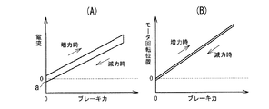
図3に示す機械的特性は、ボールランプ機構、差動減速機構等の各構成要素の機械効率が良い場合のもので、図3(B)に示すように、電動モータ23の回転位置とブレーキ力との関係は、ブレーキ力の増力時と減力時とでほぼ一致するが、図3(A)に示すように、電動モータ23に供給する電流とブレーキ力との関係は、同じブレーキ力に対して、減力時の電流は、増力時の電流よりもやや小さく、僅かなヒステリシスを有している。この場合、ヒステリシスが小さいので、減力時に電流値を0にすれば、ブレーキ力もほぼ0になる。
The mechanical characteristics of the electric disc brake
The mechanical characteristics shown in FIG. 3 are those when the mechanical efficiency of each component such as a ball ramp mechanism and a differential reduction mechanism is good. As shown in FIG. The relationship between the force and the braking force is almost the same between when the braking force is increased and when the braking force is reduced. However, as shown in FIG. 3A, the relationship between the current supplied to the
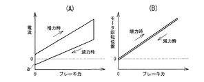
図4に示す機械的特性は、ボールランプ機構、差動減速機構等の各構成要素の機械効率があまり良くない場合のもので、図4(B)に示すように、電動モータ23の回転位置とブレーキ力との関係は、ブレーキ力の増力時と減力時とでほぼ一致するが、図4(A)に示すように、電動モータ23に供給する電流とブレーキ力との関係は、同じブレーキ力に対して、減力時の電流は、増力時の電流よりも小さく、ヒステリシスを有しており、減力時に電流値を0にしても、ブレーキ力は0にならない。この場合、減力時にブレーキ力を0にするためには、電動モータ23を逆回転させるための電流を供給する必要がある。
The mechanical characteristics shown in FIG. 4 are obtained when the mechanical efficiency of each component such as a ball ramp mechanism and a differential reduction mechanism is not so good. As shown in FIG. The relationship between the braking force and the braking force is almost the same between when the braking force is increased and when the braking force is reduced. However, as shown in FIG. 4A, the relationship between the current supplied to the
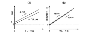
図5は、図3に示す機械的特性を有する電動ディスクブレーキ本体2に、戻しばねを設けてピストン16を後退方向に常時付勢するようにしたものの機械的特性を示している。この機械的特性では、図3に示すものと同様、図5(B)に示すように、電動モータ23の回転位置とブレーキ力との関係は、ブレーキ力の増力時と減力時とでほぼ一致し、図5(A)に示すように、電動モータ23に供給する電流とブレーキ力との関係は、同じブレーキ力に対して、減力時の電流は、増力時の電流よりもやや小さく、僅かなヒステリシスを有している。そして、ブレーキパッド10A、10Bに後退方向に戻しバネのバネ力が常時作用しているため、電動モータ23を増力方向に回転させるためには、このばね力に抗して回転する必要があり、減力時の電流も、図3に示すものよりも電流が大きくなっている。このため、電流を0にすれば、ブレーキ力は確実に0になるが、ブレーキパッド10A、10Bとディスクロータ8とのクリアランスを一定量とするためには0よりも大きな電流をかけておく必要がある。
FIG. 5 shows the mechanical characteristics of the electric disk brake
次に、上述の通常のブレーキ制御によるブレーキ動作の一例について図11のタイミングチャートを参照して説明する。
図11を参照して、時間T0でブレーキペダル3が踏込まれると、ブレーキ動作開始時に制御電流を増大させてブレーキ力を迅速に立ち上げた後、ペダルストロークに応じたブレーキ力となるように電動モータ23の回転位置を制御する。時間T1でペダルストロークが一定になると、電動モータ23の回転位置を一定に維持する。このとき、ブレーキ力は増力方向であったから、時間T1の制御電流を維持することによってブレーキ力を一定に維持することができる。
Next, an example of the brake operation by the above-described normal brake control will be described with reference to the timing chart of FIG.
Referring to FIG. 11, when the
時間T2でブレーキペダル3が戻されると、ペダルストローク3に応じたブレーキ力となるように電動モータ23の回転位置を制御する。このとき、ブレーキ力が減力方向となるので、図3乃至図5で説明した電動ディスクブレーキ本体2の機械的なヒステリシスの分だけ制御電流を減少させる。時間T3でペダルストロークが一定になると、電動モータ23の回転位置を一定に維持する。このとき、ブレーキ力は減力方向であるから、電動ディスクブレーキ本体2の機械的なヒステリシスの分だけ制御電流を増大させてブレーキ力を一定に維持する。時間T4でブレーキペダルが戻されると、ペダルストローク3に応じたブレーキ力となるように電動モータ23の回転位置を制御する。
When the
時間T5でペダルストロークが0となったとき、ブレーキパッド10A、10Bがディスクロータ8に接触するパッド接触位置に電動モータ23の回転位置を調整する。時間T6でペダルストローク0が一定時間継続すると、パッドクリアランス制御を実行してブレーキパッド10A、10Bのディスクロータ8とのクリアランスが一定量になるように電動モータ23の回転位置を制御する。時間T7でパッドクリアランスが一定量になると、電動モータ23を停止し、その回転位置制御を継続する。
When the pedal stroke becomes 0 at time T <b> 5, the rotational position of the
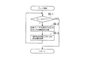
次に、図7のステップS3におけるパッド接触位置検知について、図9及び図12を参照して説明する。
図9を参照して、ステップS3−1で電動モータ23への制御電流を監視し、制御電流が規定電流に達するまで、ステップS3−2及びS3−3を実行してブレーキパッド10A、10Bを前進させる。電動モータ23への制御電流が規定電流に達したら、ステップS3−4で制御電流を0に設定し、ステップS3−5で電動モータ23への通電を停止し、ステップS3−6で電動モータ23の回転位置(停止位置)を監視する。電動モータ23の回転が停止したら、ステップS3−7で、その位置を基準位置とする。そして、ステップS3−10で電動モータ23の回転位置を監視しながらステップS3−8及びS3−9を実行してブレーキパッド10A、10Bを一定量だけ後退させ、その位置をパッド接触位置とする。
Next, the pad contact position detection in step S3 of FIG. 7 will be described with reference to FIGS.
Referring to FIG. 9, the control current to
上述のパッド接触位置検知を実行したときの電動ディスクブレーキの動作について図12のタイミングチャートを参照して説明する。
時間T0でパッド接触位置検知動作を開始し、電動モータ23に制御電流を供給してブレーキパッド10A、10Bを前進させる。時間T2でブレーキパッド10A、10Bがディスクロータ8に接触すると、電動モータ23の負荷(ピストン推力)が増大して制御電流が増大する(なお、この制御電流の増大の開始を直接検知することは困難である)。時間T2で制御電流が規定電流CSに達したら、制御電流を停止する。制御電流の停止によってブレーキパッド10A、10Bが後退し、時間T3で解放位置(フェールオープン)に達する(なお、これを直接検知することは困難である)。時間T4で電動モータ23の回転の停止を検知しとき、その位置を基準位置Xfとする。そして、パッド後退制御電流Ccによって電動モータ23を一定量だけ逆回転させて通電を停止し、その位置をパッド接触位置とする(時間T5)。その後もブレーキペダルの操作がないので、時間T6で一定量だけブレーキパッド10A、10Bを後退させる方向に電動モータ23を回転させて一定のパッドクリアランスを得る(時間T7)。
The operation of the electric disc brake when the above-described pad contact position detection is executed will be described with reference to the timing chart of FIG.
At time T0, a pad contact position detection operation is started, and a control current is supplied to the
次に、パッドクリアランス制御について図10及び図13を参照して説明する。
図10を参照して、ステップS4−1でブレーキの作動を監視し、ブレーキ作動中であれば、メインルーチンに戻る。ブレーキ作動中でなければ、ステップS4−2で現在のパッドクリアランスを検出し、ステップS4−3で現在のパッドクリアランスが規定値に達しているか否かを判断し、達していない場合には、達するまでステップS4−4、S4−5及びS4−6を実行して、電動モータ23を後退方向に回転させてブレーキパッド10A、10Bを後退させる。これにより、所定のパッドクリアランスを得る。
Next, pad clearance control will be described with reference to FIGS.
Referring to FIG. 10, the brake operation is monitored in step S4-1. If the brake is being operated, the process returns to the main routine. If the brake is not in operation, the current pad clearance is detected in step S4-2, and it is determined in step S4-3 whether the current pad clearance has reached a specified value. Steps S4-4, S4-5, and S4-6 are executed until the
パッドクリアランスが規定値に達したとき、ステップS4−7に進み、ステップS4−7で、パッド後退制御の要否を判断する。このとき、電動ディスクブレーキ本体2に大きな加速度が作用する車両の悪路走行時、旋回時等においては、その加速度によってブレーキパッド10A、10B及びピストン16が移動する虞があるため、パッド後退制御を実行せず(ノー)、ステップS4−8及びS4−9を実行して、ブレーキパッド10A、10Bの位置(パッドクリアランス)が一定(一般的には0.3mm程度)になるように電動モータ23に制御電流を供給してその位置を制御する。
When the pad clearance reaches the specified value, the process proceeds to step S4-7, and in step S4-7, it is determined whether pad retraction control is necessary. At this time, the
通常走行時には(イエス)、ステップS4−10に進み、ステップS4−10でパッドクリアランスを監視し、パッドクリアランスが制限値(一般的には0.4mm程度)に達している場合は(イエス)、ステップS4−11でパッドクリアランスの目標値を制限値に設定し、ステップS4−9を実行してパッドクリアランスを制限値に調整する。これにより、パッドクリアランスが過度に大きくなるのを防止する。 During normal driving (yes), the process proceeds to step S4-10, and the pad clearance is monitored in step S4-10. If the pad clearance has reached the limit value (generally about 0.4 mm) (yes), In step S4-11, the target value of the pad clearance is set to the limit value, and step S4-9 is executed to adjust the pad clearance to the limit value. This prevents the pad clearance from becoming excessively large.
パッドクリアランスが制限値に達していない場合には(ノー)、ステップS4−12でパッド後退制御を実行する。パッド後退制御は、所定のパッドクリアランスに調整されたブレーキパッド10A、10Bに対して、電動モータ23にピストン16を後退させる方向に、ピストン16が後退しない(位置が保持される)程度の最低電流であるパッド後退制御電流を供給することによって行われる。この場合の最低電流とは、ブレーキ力が0となるときの下限電流値付近の電流値のことであり、図3(A)に示される機械効率が良い電動ディスクブレーキ場合には、電流値の0付近(図3(A)中、aで示される部分)が最低電流となる。また、図4(A)に示される機械効率があまり良くない電動ディスクブレーキ場合には、電動モータ23を逆回転させるため電流値の下限値電流値付近(図4(A)中、aで示される部分)が最低電流となる。さらに、図5(A)に示される戻しばねを設けてピストン16を後退方向に常時付勢するようにした電動ディスクブレーキ場合には、戻しばねに抗して電動モータ23の回転を保持するとともにピストン16が後退方向に押圧されたときに戻しばねにしたがって電動モータ23の逆回転させるための電流値の下限値電流値付近(図5(A)中、bで示される部分)が最低電流となる。
If the pad clearance has not reached the limit value (No), pad retraction control is executed in step S4-12. In the pad retraction control, the minimum current is such that the
このようにパッド後退制御電流を最低電流とすることで、ディスクロータ8に面振れが生じて、ディスクロータ8がブレーキパッド10A、10Bに接触したとき、ピストン16が容易に後退するようになる。これにより、ブレーキパッド10A、10Bは、通常は、所定のパッドクリアランスを有する位置に保持されているが、制動による熱変形等によって面振れが生じてディスクロータ8がブレーキパッド10A、10Bに接触した場合には、ブレーキパッド10A、10Bを円滑に後退させることができ、ブレーキパッド10A、10Bの偏摩耗を抑制して、偏摩耗によるブレーキジャダーの発生を防止ことができる。
By setting the pad retraction control current to the minimum current in this way, surface vibration occurs in the
次に、パッド後退制御を実行したときの電動ディスクブレーキ本体2の動作について、図13のタイミングチャートを参照して説明する。なお、図13に示す例では、車速に基づいて、パッド後退制御の要否を決定しており、車速が基準車速Vsに達するまでは、パッド後退制御を実行せず、車速が基準車速Vsに達したときパッド後退制御を実行するようにしている。これは、低速時にはディスクロータ8の面振れが発生しにくくなっているためである。
Next, the operation of the electric disc brake
図13を参照して、時間T0で車速が基準車速Vsに達したとき、パッド後退制御の実行を開始し、電動モータ23にパッド後退制御電流Ccを供給してパッドクリアランスを維持したままピストン16を後退方向に付勢する。時間T1で車速が基準車速Vs未満に低下したとき、パッド後退制御を終了してパッド後退制御電流Ccを0にし、通常のパッドクリアランス制御(ブレーキパッド10A、10Bの位置制御)を実行する。
Referring to FIG. 13, when the vehicle speed reaches the reference vehicle speed Vs at time T0, execution of the pad reverse control is started, and the
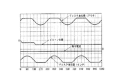
そして、図14に示すように、パッド後退制御が実行されると、回転するディスクロータ8の面振れ等によるディスクロータ8のディスク面位置の変化に対して、ディスクロータ8のブレーキパッド10A、10Bへの接触によってピストンが円滑に後退することによって、ブレーキパッド10A、10Bの偏摩耗を抑制する。
As shown in FIG. 14, when the pad retraction control is executed, the brake pads 10 </ b> A and 10 </ b> B of the
上述のパッド後退制御では、ディスクロータ8の接触によって後退したピストン16は、その位置で保持されるが、このときのピストン16の移動を監視し、面振れ等によってディスクロータ8が接触してブレーキパッド10A、10B(ピストン16)が後退したとき、パッド後退制御電流を増大させて、その後退位置から更に一定量だけピストン16を後退させるようにしてもよい。これにより、ブレーキパッド10A、10Bの偏摩耗を効果的に抑制することができる。
In the above-described pad retraction control, the
また、上述の例では、パッド後退制御電流Ccとして一定の電流を供給するようにしているが、パッド後退制御電流を所定のパターンで変動させてもよく、いわゆるディザ電流を重畳するようにしてもよい。 In the above example, a constant current is supplied as the pad retraction control current Cc. However, the pad retraction control current may be varied in a predetermined pattern, or a so-called dither current may be superimposed. Good.
1 電動ディスクブレーキ、7 コントローラ(制御手段)、8 ディスクロータ、10A、10Bブレーキパッド、16 ピストン(パッド押圧部材)、17 ボールランプ機構(回転−直動変換機構)、23 電動モータ、26 レゾルバ(位置検出手段) DESCRIPTION OF SYMBOLS 1 Electric disc brake, 7 Controller (control means), 8 Disc rotor, 10A, 10B brake pad, 16 Piston (pad pressing member), 17 Ball ramp mechanism (rotation-linear motion conversion mechanism), 23 Electric motor, 26 Resolver ( Position detection means)
Claims (7)
該電動モータの回転運動を直線運動に変換する回転−直動変換機構と、
該回転−直動変換機構の直線運動によってブレーキパッドをディスクロータに押圧するパッド押圧部材と、
制動時に前記パッド押圧部材に目標推力を発生させるように前記電動モータに電流を供給する制御手段と、を有し、
非制動時に前記パッド押圧部材がブレーキパッドとディスクロータとのクリアランスを保持する電動ディスクブレーキにおいて、
前記制御手段は、非制動時に回転する前記ディスクロータが前記ブレーキパッドに接触したとき、該ブレーキパッドを介して伝わる前記ディスクロータからの力によって前記パッド押圧部材が後退するのを許す大きさのパッド後退制御電流を非制動中に前記電動モータへ供給することを特徴とする電動ディスクブレーキ。 An electric motor;
A rotation-linear motion conversion mechanism for converting the rotational motion of the electric motor into linear motion;
A pad pressing member that presses the brake pad against the disc rotor by a linear motion of the rotation-linear motion conversion mechanism;
And control means for supplying a current to the electric motor so as to generate a target thrust to the pad pressing member at the time of braking has,
In the electric disc brake in which the pad pressing member holds the clearance between the brake pad and the disc rotor during non-braking,
Wherein, when the disc rotor rotating at the time of non-braking is in contact with the brake pad, the size of the pad the pad pressing member by a force from the disc rotor transmitted through the brake pad allows to retract electric disc brake and supplying to the electric motor to reverse control current during non-braking.
前記制御手段は、非制動時に、前記パッド押圧部材の位置を維持する保持力に吊り合うような該パッド押圧部材を後退させる方向の付勢力を発生するように前記電動モータに前記パッド後退制御電流を供給して、回転する前記ディスクロータが前記ブレーキパッドに接触したとき、前記ディスクロータからの力によって前記ブレーキパッドの後退を促進することを特徴とする請求項1に記載の電動ディスクブレーキ。 The pad pressing member is pre-SL control means have mechanical properties that will be retained in that position even when cut off the supply of current to the electric motor,
Wherein, during non-braking, the pad retracting control to the electric motor to generate said pad pressing direction biasing force of the retracting the pad pressing member, such as mutually hanging the holding force to maintain the position of the member 2. The electric disc brake according to claim 1, wherein when the rotating disc rotor contacts the brake pad by supplying an electric current, the brake pad is moved backward by a force from the disc rotor .
前記制御手段は、非制動時に前記パッド押圧部材を所定位置に戻した後、前記パッド押圧部材を所定位置に保持し得る最低電流である前記パッド後退制御電流を前記電動モータに供給することを特徴とする請求項1に記載の電動ディスクブレーキ。 The pad pressing member is constantly urged in the backward direction by the urging means,
The control means supplies the pad reverse control current, which is a minimum current capable of holding the pad pressing member in a predetermined position, to the electric motor after returning the pad pressing member to a predetermined position during non-braking. The electric disc brake according to claim 1.
Priority Applications (3)
| Application Number | Priority Date | Filing Date | Title |
|---|---|---|---|
| JP2007199537A JP4973994B2 (en) | 2007-07-31 | 2007-07-31 | Electric disc brake |
| US12/219,423 US8235474B2 (en) | 2007-07-31 | 2008-07-22 | Electric disk brake |
| EP08013347.3A EP2030854B1 (en) | 2007-07-31 | 2008-07-24 | Electric disk brake |
Applications Claiming Priority (1)
| Application Number | Priority Date | Filing Date | Title |
|---|---|---|---|
| JP2007199537A JP4973994B2 (en) | 2007-07-31 | 2007-07-31 | Electric disc brake |
Publications (3)
| Publication Number | Publication Date |
|---|---|
| JP2009035069A JP2009035069A (en) | 2009-02-19 |
| JP2009035069A5 JP2009035069A5 (en) | 2010-09-09 |
| JP4973994B2 true JP4973994B2 (en) | 2012-07-11 |
Family
ID=40257002
Family Applications (1)
| Application Number | Title | Priority Date | Filing Date |
|---|---|---|---|
| JP2007199537A Expired - Fee Related JP4973994B2 (en) | 2007-07-31 | 2007-07-31 | Electric disc brake |
Country Status (3)
| Country | Link |
|---|---|
| US (1) | US8235474B2 (en) |
| EP (1) | EP2030854B1 (en) |
| JP (1) | JP4973994B2 (en) |
Families Citing this family (11)
| Publication number | Priority date | Publication date | Assignee | Title |
|---|---|---|---|---|
| US8220594B2 (en) * | 2007-08-30 | 2012-07-17 | Nippon Soken, Inc | Electric brake device |
| JP5333114B2 (en) * | 2009-09-18 | 2013-11-06 | 株式会社アドヴィックス | Parking brake control device |
| JP5436191B2 (en) * | 2009-12-21 | 2014-03-05 | Ntn株式会社 | Wheel bearing device with in-wheel motor built-in sensor |
| JP5737500B2 (en) * | 2011-01-31 | 2015-06-17 | 日立オートモティブシステムズ株式会社 | Electric brake device |
| JP5637067B2 (en) * | 2011-05-24 | 2014-12-10 | 株式会社アドヴィックス | Electric brake device and control method of electric brake device |
| JP6338902B2 (en) * | 2014-03-24 | 2018-06-06 | Ntn株式会社 | Electric brake device and electric brake device system |
| DE102015001152A1 (en) * | 2015-02-02 | 2016-08-04 | Wabco Europe Bvba | Method for monitoring a brake for motor vehicles, brake system for carrying out the method and motor vehicle with such |
| DE102015211359A1 (en) | 2015-06-19 | 2017-01-05 | Volkswagen Aktiengesellschaft | Preparation of a braking process in a motor vehicle |
| KR102500083B1 (en) * | 2018-03-08 | 2023-02-15 | 에이치엘만도 주식회사 | Electric brake system and controlling method thereof |
| EP3858688A4 (en) * | 2018-09-26 | 2021-11-10 | Hitachi Astemo, Ltd. | Electric brake, and control device |
| JP7169839B2 (en) * | 2018-10-11 | 2022-11-11 | 日立Astemo株式会社 | Brake control device and brake system |
Family Cites Families (17)
| Publication number | Priority date | Publication date | Assignee | Title |
|---|---|---|---|---|
| KR100567637B1 (en) * | 1997-11-22 | 2006-04-05 | 콘티넨탈 테베스 아게 운트 코. 오하게 | Method and system for controlling an electromechanically actuated parking brake for motor vehicles |
| JP4000675B2 (en) * | 1998-07-02 | 2007-10-31 | 住友電気工業株式会社 | Brake device for vehicle |
| US6250436B1 (en) * | 1998-07-31 | 2001-06-26 | Tokico Ltd. | Motor-driven brake apparatus |
| JP3695171B2 (en) * | 1998-09-18 | 2005-09-14 | トヨタ自動車株式会社 | Electric brake device for vehicle |
| JP2001032868A (en) * | 1999-07-21 | 2001-02-06 | Nissan Motor Co Ltd | Electric brake system |
| US6969126B2 (en) * | 2000-02-28 | 2005-11-29 | Hitachi, Ltd. | Braking apparatus and method of controlling the same |
| JP4248729B2 (en) * | 2000-05-31 | 2009-04-02 | 株式会社日立製作所 | Electric brake device |
| US6626269B2 (en) * | 2000-08-08 | 2003-09-30 | Delphi Technologies, Inc. | Zero drag disc brake with anti-knock-back device |
| JP3740007B2 (en) * | 2000-09-28 | 2006-01-25 | トヨタ自動車株式会社 | Control device for vehicle brake |
| JP2002213507A (en) * | 2001-01-17 | 2002-07-31 | Nissan Motor Co Ltd | Electric brake device |
| JP3936210B2 (en) | 2001-10-22 | 2007-06-27 | 株式会社日立製作所 | Electric disc brake and its control program |
| DE10152423C2 (en) * | 2001-10-24 | 2003-08-21 | Lucas Automotive Gmbh | disc brake |
| US7481301B2 (en) * | 2003-11-17 | 2009-01-27 | Arvinmeritor Technology, Llc | Force sensor for vehicle brake application |
| US7467692B2 (en) * | 2005-03-17 | 2008-12-23 | Honeywell International Inc. | Method of and system for reducing power required for an electric brake to maintain a static force |
| JP2007199537A (en) | 2006-01-27 | 2007-08-09 | Murata Mach Ltd | Image forming apparatus |
| US8544966B2 (en) * | 2008-01-17 | 2013-10-01 | Advics Co., Ltd. | Brake controller for vehicle and brake control method for vehicle |
| JP2009173082A (en) * | 2008-01-22 | 2009-08-06 | Hitachi Ltd | Brake system |
-
2007
- 2007-07-31 JP JP2007199537A patent/JP4973994B2/en not_active Expired - Fee Related
-
2008
- 2008-07-22 US US12/219,423 patent/US8235474B2/en active Active
- 2008-07-24 EP EP08013347.3A patent/EP2030854B1/en active Active
Also Published As
| Publication number | Publication date |
|---|---|
| JP2009035069A (en) | 2009-02-19 |
| EP2030854A3 (en) | 2015-01-14 |
| EP2030854B1 (en) | 2020-03-25 |
| EP2030854A2 (en) | 2009-03-04 |
| US8235474B2 (en) | 2012-08-07 |
| US20090032342A1 (en) | 2009-02-05 |
Similar Documents
| Publication | Publication Date | Title |
|---|---|---|
| JP4973994B2 (en) | Electric disc brake | |
| JP2009173082A (en) | Brake system | |
| JP4741525B2 (en) | Electric brake device | |
| JP5206952B2 (en) | Disc brake device | |
| US10611350B2 (en) | Electric brake device | |
| JP2010052643A (en) | Disk brake device | |
| JP5614528B2 (en) | Disc brake | |
| JP4546976B2 (en) | Brake device | |
| US10507810B2 (en) | Electric brake device | |
| US11498534B2 (en) | Electric brake device | |
| US20220032885A1 (en) | Electric brake, and control device | |
| JP2000055093A (en) | Electrically driven disc brake device | |
| JP4556153B2 (en) | Electric disc brake | |
| JP4191871B2 (en) | Brake device | |
| JP7366248B2 (en) | electric brake device | |
| JP6900881B2 (en) | Electric brake control device | |
| JP2003104195A (en) | Electric brake device | |
| JPH11257382A (en) | Motor-operated disk brake | |
| JP2008115880A (en) | Electric disc-brake | |
| JP5085108B2 (en) | Electric disc brake device | |
| JP2012245975A (en) | Brake system | |
| JP2010006165A (en) | Electric disc brake | |
| JP5387830B2 (en) | Electric disc brake | |
| JP2005104261A (en) | Brake device | |
| JP2020026240A (en) | Brake system for vehicle |
Legal Events
| Date | Code | Title | Description |
|---|---|---|---|
| A711 | Notification of change in applicant |
Free format text: JAPANESE INTERMEDIATE CODE: A712 Effective date: 20090907 |
|
| RD03 | Notification of appointment of power of attorney |
Free format text: JAPANESE INTERMEDIATE CODE: A7423 Effective date: 20090907 |
|
| A521 | Request for written amendment filed |
Free format text: JAPANESE INTERMEDIATE CODE: A523 Effective date: 20100723 |
|
| A621 | Written request for application examination |
Free format text: JAPANESE INTERMEDIATE CODE: A621 Effective date: 20100723 |
|
| A977 | Report on retrieval |
Free format text: JAPANESE INTERMEDIATE CODE: A971007 Effective date: 20111209 |
|
| A131 | Notification of reasons for refusal |
Free format text: JAPANESE INTERMEDIATE CODE: A131 Effective date: 20111214 |
|
| A521 | Request for written amendment filed |
Free format text: JAPANESE INTERMEDIATE CODE: A523 Effective date: 20120210 |
|
| TRDD | Decision of grant or rejection written | ||
| A01 | Written decision to grant a patent or to grant a registration (utility model) |
Free format text: JAPANESE INTERMEDIATE CODE: A01 Effective date: 20120229 |
|
| A01 | Written decision to grant a patent or to grant a registration (utility model) |
Free format text: JAPANESE INTERMEDIATE CODE: A01 |
|
| A61 | First payment of annual fees (during grant procedure) |
Free format text: JAPANESE INTERMEDIATE CODE: A61 Effective date: 20120329 |
|
| R150 | Certificate of patent or registration of utility model |
Ref document number: 4973994 Country of ref document: JP Free format text: JAPANESE INTERMEDIATE CODE: R150 Free format text: JAPANESE INTERMEDIATE CODE: R150 |
|
| FPAY | Renewal fee payment (event date is renewal date of database) |
Free format text: PAYMENT UNTIL: 20150420 Year of fee payment: 3 |
|
| FPAY | Renewal fee payment (event date is renewal date of database) |
Free format text: PAYMENT UNTIL: 20150420 Year of fee payment: 3 |
|
| R250 | Receipt of annual fees |
Free format text: JAPANESE INTERMEDIATE CODE: R250 |
|
| S533 | Written request for registration of change of name |
Free format text: JAPANESE INTERMEDIATE CODE: R313533 |
|
| R350 | Written notification of registration of transfer |
Free format text: JAPANESE INTERMEDIATE CODE: R350 |
|
| R250 | Receipt of annual fees |
Free format text: JAPANESE INTERMEDIATE CODE: R250 |
|
| LAPS | Cancellation because of no payment of annual fees |