JP4972340B2 - Structure of bottom plate liner of water-sealed metal conveyor - Google Patents
Structure of bottom plate liner of water-sealed metal conveyor Download PDFInfo
- Publication number
- JP4972340B2 JP4972340B2 JP2006132090A JP2006132090A JP4972340B2 JP 4972340 B2 JP4972340 B2 JP 4972340B2 JP 2006132090 A JP2006132090 A JP 2006132090A JP 2006132090 A JP2006132090 A JP 2006132090A JP 4972340 B2 JP4972340 B2 JP 4972340B2
- Authority
- JP
- Japan
- Prior art keywords
- bottom plate
- water
- scraper
- plate liner
- liner
- Prior art date
- Legal status (The legal status is an assumption and is not a legal conclusion. Google has not performed a legal analysis and makes no representation as to the accuracy of the status listed.)
- Active
Links
- 239000002184 metal Substances 0.000 title claims description 126
- XLYOFNOQVPJJNP-UHFFFAOYSA-N water Substances O XLYOFNOQVPJJNP-UHFFFAOYSA-N 0.000 claims description 166
- 238000002844 melting Methods 0.000 claims description 21
- 230000008018 melting Effects 0.000 claims description 21
- 239000000498 cooling water Substances 0.000 claims description 17
- 238000005469 granulation Methods 0.000 claims description 17
- 230000003179 granulation Effects 0.000 claims description 17
- 238000000197 pyrolysis Methods 0.000 description 12
- 239000007769 metal material Substances 0.000 description 6
- 238000010079 rubber tapping Methods 0.000 description 5
- 239000002699 waste material Substances 0.000 description 5
- 239000002956 ash Substances 0.000 description 4
- 239000010881 fly ash Substances 0.000 description 4
- 239000000155 melt Substances 0.000 description 4
- 238000003466 welding Methods 0.000 description 4
- 230000000630 rising effect Effects 0.000 description 3
- 238000007790 scraping Methods 0.000 description 3
- 229910000831 Steel Inorganic materials 0.000 description 2
- 239000008187 granular material Substances 0.000 description 2
- 239000000463 material Substances 0.000 description 2
- 239000007921 spray Substances 0.000 description 2
- 239000010959 steel Substances 0.000 description 2
- 238000005452 bending Methods 0.000 description 1
- 238000001816 cooling Methods 0.000 description 1
- 238000010298 pulverizing process Methods 0.000 description 1
- 238000005507 spraying Methods 0.000 description 1
- 239000000758 substrate Substances 0.000 description 1
Images


Landscapes
- Pusher Or Impeller Conveyors (AREA)
- Gasification And Melting Of Waste (AREA)
- Furnace Details (AREA)
Description
本発明は、主にごみ焼却炉から排出された焼却灰や飛灰、或いは廃棄物の乾留熱分解により生成された熱分解残渣を溶融処理する電気式溶融炉等の各種溶融炉に付設され、溶融炉から抜き出した溶融メタルを水槽に設けた水砕ノズルにより水砕して粒状のメタルとし、水槽内に沈降した粒状のメタルをスクレーパーにより掻き揚げて水面上へ搬送するようにした水封式メタルコンベヤに用いられるものであり、特に、水槽の底板に設けた底板ライナーに改良を加えることによって、スクレーパーの底面の偏摩耗を防止できると共に、粒状のメタルの搬送効率の向上を図れるようにした水封式メタルコンベヤの底板ライナーの構造に関するものである。 The present invention is attached to various melting furnaces such as an electric melting furnace that mainly melts incineration ash and fly ash discharged from a waste incinerator, or pyrolysis residue generated by dry distillation pyrolysis of waste, Water-sealed type that melted metal extracted from the melting furnace is granulated with a granulation nozzle provided in the water tank to form granular metal, and the granular metal settled in the water tank is scraped up by a scraper and conveyed onto the water surface It is used for metal conveyors, and in particular, by improving the bottom plate liner provided on the bottom plate of the water tank, it is possible to prevent uneven wear on the bottom surface of the scraper and improve the efficiency of conveying granular metal. The present invention relates to the structure of the bottom plate liner of a water-sealed metal conveyor.
一般に、ごみ焼却炉から排出される焼却灰や飛灰、或いは乾留熱分解ドラムから排出される熱分解残渣等を溶融処理する電気式溶融炉等の溶融炉に於いては、溶融炉から抜き出した溶融メタルを流下させる下り傾斜状のメタル出湯樋の下方位置に水封式メタルコンベヤが設置されている(例えば、特許文献1参照)。
この水封式メタルコンベヤは、溶融炉から抜き出した溶融メタルを水槽内に設置した水砕ノズルにより水砕して粒状のメタルとし、水槽内に沈降した粒状のメタルをスクレーパーで掻き揚げて水面上へ搬送するようにしたものである。
In general, in melting furnaces such as electric melting furnaces that melt incineration ash and fly ash discharged from waste incinerators or pyrolysis residues discharged from dry distillation pyrolysis drums, etc., they are extracted from the melting furnace. A water-sealed metal conveyor is installed at a lower position of a downward sloping metal tap that allows molten metal to flow down (see, for example, Patent Document 1).
This water-sealed metal conveyor is made by granulating the molten metal extracted from the melting furnace with a granulation nozzle installed in the water tank to form granular metal, and scraping the granular metal that has settled in the water tank with a scraper on the surface of the water. It is intended to be transported to.
即ち、前記水封式メタルコンベヤ1は、図5に示す如く、溶融炉10のメタル出湯樋11の下方位置に配置され、一定量の冷却水Wを貯留した水槽2と、水槽2内に回転自在に配設された複数のスプロケット7と、各スプロケット7に巻き回された対向する一対の無端状のチェーン3と、一対の無端状のチェーン3間にその走行方向に一定間隔毎に取り付けられ、水槽2内に沈降した粒状のメタルを掻き揚げる複数のスクレーパー4と、駆動用のスプロケット7を回転駆動するモータ等の駆動部(図示省略)と、水槽2内の水面付近に設けられ、メタル出湯樋11から水槽2内に落下する溶融メタルへ冷却水Wを噴射して溶融メタルを水砕する水砕ノズル8とから構成されており、メタル出湯樋11上から水槽2内へ落下する溶融メタルを水砕ノズル8から噴射される冷却水Wにより水砕して細かな粒状のメタルとし、水槽2の底板2a上に沈降した粒状のメタルをスクレーパー4により掻き揚げて水面上へ搬送し、当該粒状のメタルを水槽2の端部に形成したメタル排出口(図示省略)から水槽2外へ排出するようになっている。
That is, as shown in FIG. 5, the water-sealed
ところで、水封式メタルコンベヤ1に於いては、スクレーパー4の底面と水槽2の底板2aとを直接接触させた場合には、比較的硬度の高い細かな粒状のメタルがスクレーパー4と水槽2の底板2aとの間に研磨剤のように介在し、水槽2の底板2aを著しく摩耗させたり、或いは損傷を与えたりして水槽2の耐久性が極端に悪くなるため、水槽2の底板2a上には、スクレーパー4の底面と水槽2の底板2aとが直接接触しないように底板ライナー9が設けられている。
この底板ライナー9は、図5及び図6に示す如く、鋼材等により断面形状が矩形の帯状に形成されており、水槽2の底板2a上にメタルの搬送方向(スクレーパー4の進行方向)に沿って複数本配設されている。これによって、水槽2の底板2aの摩耗や損傷が防止されることになる。
By the way, in the water-sealed
As shown in FIGS. 5 and 6, the
然し乍ら、前記底板ライナー9は、メタルの搬送方向(スクレーパー4の進行方向)と平行に配設されているため、スクレーパー4の底面の同じ位置が常に底板ライナー9と連続して接触することになり、スクレーパー4の底面の底板ライナー9と接触する部分が短期間で凹状に偏摩耗すると云う問題があった。
又、溶融メタルの出湯中には、水槽2内の水砕ノズル8から冷却水Wが噴射されて水槽2内に常時水流が発生しているため、粒状のメタルをスクレーパー4で掻き揚げて水面上へ搬送する際に帯状の底板ライナー9がメタルの搬送方向(スクレーパー4の進行方向)と平行に配設されていることとも相俟って、水面付近では水砕ノズル8からの噴射水流の影響によりスクレーパー4と水槽2の底板2aとの隙間から粒状のメタルが水中へ流れ落ち、粒状のメタルを水面上へ搬送できないと云う問題が発生している。そのため、実際には、溶融メタルの出湯後(水砕ノズル8の冷却水Wの噴射停止後)の水槽2内の水流が止まった後に、スクレーパー4による粒状のメタルの搬送が可能となっている。
In addition, since the cooling water W is sprayed from the water granulation nozzle 8 in the
本発明は、このような問題点に鑑みて為されたものであり、その目的は、水槽の底板上に沈降した粒状のメタルを掻き揚げて搬送するスクレーパーの底面の偏摩耗を防止できると共に、スクレーパーによる粒状のメタルの搬送効率の向上を図れるようにした水封式メタルコンベヤの底板ライナーの構造を提供することにある。 The present invention has been made in view of such problems, and its purpose is to prevent uneven wear on the bottom surface of the scraper that scrapes and conveys the granular metal settled on the bottom plate of the water tank, It is an object of the present invention to provide a structure of a bottom plate liner of a water-sealed metal conveyor which can improve the efficiency of conveying granular metal by a scraper.
上記目的を達成するために、本発明の請求項1の発明は、溶融炉から抜き出した溶融メタルを水槽に設けた水砕ノズルから噴射される冷却水により水砕して粒状のメタルとし、水槽内に沈降した粒状のメタルを水槽の底板に設けた底板ライナー上を摺動するスクレーパーにより掻き揚げて水面上へ搬送するようにした水封式メタルコンベヤの底板ライナーの構造であって、前記底板ライナーの構造は、水槽の底板上にメタルの搬送方向に沿って配設され、スクレーパーの底面の一部分に接触する直線状又はジグザグ状の主底板ライナーと、主底板ライナーの長さ方向に間隔をおいた複数箇所の両側又は片側に枝状に取り付けられ、その何れかの部分が、移動するスクレーパーの底面の横幅方向の主底板ライナーと接触する部分以外の全部分に接触する複数本の直線状の補助底板ライナーとから成り、前記スクレーパーの底面が主底板ライナーと補助底板ライナーの両方のライナーに接触しながら摺動し、スクレーパーの進行中に主底板ライナーと補助底板ライナーによりスクレーパーの底面全域が接触摺動を受けるようにしたことに特徴がある。
In order to achieve the above-mentioned object, the invention of
又、本発明の請求項2の発明は、補助底板ライナーを主底板ライナーの両側又は片側に主底板ライナーの長手方向へ一定の間隔を空けて取り付け、水槽の水面付近に位置する補助底板ライナーによりスクレーパーで水面付近へ掻き揚げられた粒状のメタルが水砕ノズルからの噴射水流の影響を受け難くし、水面付近へ掻き揚げられた粒状のメタルが水面付近へ移動したスクレーパーの底面と水槽の底板との隙間から流れ落ちないようにしたことに特徴がある。 According to the second aspect of the present invention, the auxiliary bottom plate liner is attached to both sides or one side of the main bottom plate liner at a certain interval in the longitudinal direction of the main bottom plate liner, and the auxiliary bottom plate liner is located near the water surface of the water tank. The granular metal scraped up to the surface of the water by the scraper is less affected by the water flow from the granulating nozzle, and the granular metal scraped up to the surface of the water moved to the surface of the scraper and the bottom plate of the tank It is characterized by not flowing down from the gap .
本発明の水封式メタルコンベヤの底板ライナーの構造は、水槽の底板上に直線状又はジグザグ状の主底板ライナーをメタルの搬送方向に沿って配設し、前記主底板ライナーに複数本の直線状の補助底板ライナーを枝状に取り付け、スクレーパーの底面全域が主底板ライナー及び補助底板ライナーに接触しながら摺動する構成としているため、粒状のメタルを掻き揚げて水面上へ搬送する際にスクレーパーの底面全域が前記各底板ライナーに均等に接触しながら進行することになる。その結果、スクレーパーの底面の偏摩耗を防止することができ、スクレーパーの延命化を図れる。
又、本発明の水封式メタルコンベヤの底板ライナーの構造は、補助底板ライナーを主底板ライナーの両側又は片側に主底板ライナーの長手方向へ一定の間隔を空けて取り付け、水槽の水面付近に位置する補助底板ライナーによりスクレーパーの底面と水槽の底板との隙間へ水砕ノズルからの噴射水流が入り込むのを阻止するようにしているため、水槽の水面付近では補助底板ライナーがあることによりスクレーパーで水面付近へ
掻き揚げられた粒状のメタルが水砕ノズルからの噴射水流の影響を受けることがなくなる。その結果、粒状のメタルがスクレーパーと水槽の底板との隙間から流れ落ちることがなくなり、溶融メタルの出湯中(水砕ノズルからの冷却水の噴射中)でも粒状のメタルを順次搬送することができ、搬送効率の向上を図れる。
The structure of the bottom plate liner of the water-sealed metal conveyor of the present invention is such that a linear or zigzag main bottom plate liner is disposed along the metal conveying direction on the bottom plate of the water tank, and a plurality of straight lines are arranged on the main bottom plate liner. -Like auxiliary bottom plate liner is attached in a branch shape, and the entire bottom surface of the scraper slides in contact with the main bottom plate liner and auxiliary bottom plate liner, so when scraping the granular metal and transporting it to the water surface The entire bottom surface of the substrate proceeds while contacting the respective bottom plate liners evenly. As a result, uneven wear on the bottom surface of the scraper can be prevented, and the life of the scraper can be extended.
Further, the structure of the bottom plate liner of the water-sealed metal conveyor of the present invention is such that the auxiliary bottom plate liner is attached to both sides or one side of the main bottom plate liner at a certain interval in the longitudinal direction of the main bottom plate liner, and is located near the water surface of the water tank. Since the auxiliary bottom plate liner prevents the spray water flow from the granulation nozzle from entering the gap between the bottom surface of the scraper and the bottom plate of the water tank, there is an auxiliary bottom plate liner near the water surface of the water tank, The granular metal scraped up to the vicinity is not affected by the jet water flow from the granulating nozzle. As a result, the granular metal does not flow down from the gap between the scraper and the bottom plate of the water tank, and the granular metal can be transported sequentially even during the molten metal tapping (while the cooling water is being sprayed from the granulation nozzle). The conveyance efficiency can be improved.
以下、本発明の実施の形態を図面に基づいて詳細に説明する。
図1及び図2は本発明の実施の形態に係る底板ライナーの構造を採用した水封式メタルコンベヤ1の要部を示し、当該水封式メタルコンベヤ1は、ごみ焼却炉から排出された焼却灰や飛灰、或いは乾留熱分解ドラムから排出された熱分解残渣等を溶融処理する電気溶融炉等の溶融炉(図示省略)に付設されており、溶融炉から抜き出した溶融メタルを水槽2に設けた水砕ノズル(図示省略)により水砕して粒状のメタルとし、水槽2内に沈降した粒状のメタルをスクレーパー4により掻き揚げて水面上へ搬送するようにしたものである。
Hereinafter, embodiments of the present invention will be described in detail with reference to the drawings.
1 and 2 show a main part of a water-sealed
即ち、水封式メタルコンベヤ1は、溶融炉から抜き出した溶融メタルを流下させる下り傾斜状のメタル出湯樋(図示省略)の下方位置に設置されており、溶融炉のメタル出湯樋の下方位置に配置され、一定量の冷却水を貯留した水槽2と、水槽2内に回転自在に配設された複数のスプロケット(図示省略)と、各スプロケットに巻き回された対向する一対の無端状のチェーン3と、一対の無端状のチェーン3間にその走行方向に一定間隔毎に取り付けられ、水槽2内に沈降した粒状のメタルを掻き揚げる複数のスクレーパー4と、駆動用のスプロケットを回転駆動するモータ等の駆動部(図示省略)と、水槽2内の水面付近に設けられ、メタル出湯樋から水槽2内に落下する溶融メタルへ冷却水を噴射して溶融メタルを水砕する水砕ノズル(図示省略)と、水槽2の底板2a上に設けられ、水槽2の底板2aやスクレーパー4の摩耗、損傷等を防止する主底板ライナー5及び補助底板ライナー6とから構成されている。
That is, the water-sealed
前記水槽2は、鋼板材等により細長いボックス状に形成されており、その内部にはメタル出湯樋から落下する溶融メタルを急冷固化するための冷却水が一定の水位を保つように貯留されている。
又、水槽2の底板2aは、底板2a上に沈降した粒状のメタルをスクレーパー4により水面上へ搬送できるように水槽2の一端部から他端部へ向かって昇り傾斜状に形成されている。
更に、水槽2の他端部には、スクレーパー4により水面上へ掻き揚げられた粒状のメタルを水槽2外へ排出するためのメタル排出口(図示省略)が形成されている。
The
The
Further, a metal discharge port (not shown) is formed at the other end of the
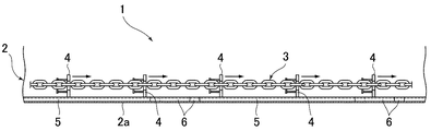
本発明の実施の形態に係る底板ライナーの構造は、図1及び図2に示す如く、水槽2の底板2a上にメタルの搬送方向(スクレーパー4の進行方向)に沿う姿勢で配設され、スクレーパー4の底面の一部分に接触する二本の直線状の主底板ライナー5と、各主底板ライナー5の両側に枝状に取り付けられ、スクレーパー4の主底板ライナー5と接触する部分以外の底面部分に接触する複数本の直線状の補助底板ライナー6とから成り、スクレーパー4の底面全域が前記主底板ライナー5及び補助底板ライナー6に接触しながら摺動するように構成されている。
As shown in FIGS. 1 and 2, the structure of the bottom plate liner according to the embodiment of the present invention is disposed on the
具体的には、前記各主底板ライナー5は、断面形状がコの字形に形成された長尺状の金属材により形成されており、水槽2の底板2a上にメタルの搬送方向(スクレーパー4の進行方向)に沿う姿勢で且つ水槽2の幅方向に一定の間隔を空けて対向状に配設されている。これら各主底板ライナー5は、コの字形の開放された部分が水槽2の底板2aへ向く姿勢で水槽2の底板2a上に溶接により固着されている。
Specifically, each of the main
一方、前記各補助底板ライナー6は、断面形状がコの字形に形成された短尺状の金属材により形成されており、各主底板ライナー5の両側にメタルの搬送方向(スクレーパー4の進行方向)に一定の間隔を空けて配設され、スクレーパー4の進行方向に対して傾斜する姿勢でもってその基端部側が主底板ライナー5に取り付けられている。これら各補助底板ライナー6は、その先端部側がスクレーパー4の進行方向へ向いており、コの字形の開放された部分が水槽2の底板2aへ向く姿勢で水槽2の底板2a上に溶接により固着されている。
又、水槽2の水面付近に位置する補助底板ライナー6は、水砕ノズルからの噴射水流がスクレーパー4の底面と水槽2の底板2aとの隙間へ入り込むのを阻止する役目を果たしている。
尚、一方の主底板ライナー5に取り付けた補助底板ライナー6と他方の主底板ライナー5に取り付けた補助底板ライナー6とは、スクレーパー4の進行方向に向かって齟齬状態になるように水槽2の底板2a上に配置されている。
On the other hand, each of the auxiliary
Further, the auxiliary
The auxiliary
次に、本発明の底板ライナーの構造を採用した水封式メタルコンベヤ1を用いて溶融炉から抜き出した溶融メタルを水砕処理する場合について説明する。
溶融炉から抜き出した溶融メタルは、メタル出湯樋を流下してメタル出湯樋から水槽2内に落下し、水砕ノズルから噴射される冷却水により水砕された後、水槽2内の冷却水により完全冷却されて粒状のメタルとなって水槽2の底板2a上に沈降する。
Next, the case where the molten metal extracted from the melting furnace using the water-sealed
The molten metal extracted from the melting furnace flows down the metal tap and falls into the
水槽2の底板2a上に沈降した粒状のメタルは、水槽2の底板2a上に設けた主底板ライナー5及び補助底板ライナー6上を摺動しながら水槽2のメタル排出口側へ向かって進行するスクレーパー4により掻き取られ、水槽2の昇り傾斜状の底板2a上を掻き揚げられて水面上へ搬送される。
The granular metal settled on the
このとき、スクレーパー4は、その底面全域が水槽2の底板2a上に配設した主底板ライナー5及び補助底板ライナー6に均等に接触しながら進行するため、スクレーパー4の底面の偏摩耗が防止されることになり、スクレーパー4の延命化を図れる。
又、スクレーパー4が水面付近に移動したときには、水面付近に位置する補助底板ライナー6がスクレーパー4の底面と水槽2の昇り傾斜状の底板2aとの隙間へ水砕ノズルからの噴射水流が入り込むのを阻止しているため、スクレーパー4により水面付近へ掻き揚げられた粒状のメタルが水砕ノズルからの噴射水流の影響を受け難くなり、水面付近へ掻き揚げられた粒状のメタルがスクレーパー4の底面と水槽2の底板2aとの隙間から流れ落ちることがない。その結果、溶融メタルの出湯中(水砕ノズルからの冷却水の噴射中)でも粒状のメタルを順次搬送することができ、搬送効率の向上を図れる。
At this time, the
Further, when the
そして、スクレーパー4により水面上へ搬送された粒状のメタルは、水槽2の端部に形成したメタル排出口から水槽2外へ排出される。
And the granular metal conveyed on the water surface by the
このように、前記水封式メタルコンベヤ1によれば、水槽2の底板2a上に二本の直線状の主底板ライナー5と複数本の補助底板ライナー6とを適宜に配設しているため、スクレーパー4の底面の偏摩耗を防止できると共に、粒状のメタルの搬送効率の向上を図ることができる。
Thus, according to the water-sealed
図3及び図4は本発明の他の実施の形態に係る底板ライナーの構造を採用した水封式メタルコンベヤ1の要部を示し、当該水封式メタルコンベヤ1は、ごみ焼却炉から排出された焼却灰や飛灰、或いは乾留熱分解ドラムから排出された熱分解残渣等を溶融処理する電気溶融炉等の溶融炉(図示省略)に付設されており、溶融炉から抜き出した溶融メタルを水槽2に設けた水砕ノズルにより水砕して粒状のメタルとし、水槽2内に沈降した粒状のメタルをスクレーパー4により掻き揚げて水面上へ搬送するようにしたものである。
3 and 4 show the main part of a water-sealed
即ち、水封式メタルコンベヤ1は、図1及び図2に示す水封式メタルコンベヤ1と同様に、溶融炉のメタル出湯樋の下方位置に配置され、一定量の冷却水を貯留した水槽2と、水槽2内に回転自在に配設された複数のスプロケット(図示省略)と、各スプロケットに巻き回された対向する一対の無端状のチェーン3と、一対の無端状のチェーン3間にその走行方向に一定間隔毎に取り付けられ、水槽2内に沈降した粒状のメタルを掻き揚げる複数のスクレーパー4と、駆動用のスプロケットを回転駆動するモータ等の駆動部(図示省略)と、水槽2内の水面付近に設けられ、メタル出湯樋から水槽2内に落下する溶融メタルへ冷却水を噴射して溶融メタルを水砕する水砕ノズル(図示省略)と、水槽2の底板2a上に設けられ、水槽2の底板2aやスクレーパー4の摩耗、損傷等を防止する主底板ライナー5及び補助底板ライナー6とから構成されている。
That is, the water-sealed
本発明の他の実施の形態に係る底板ライナーの構造は、水槽2の底板2a上にメタルの搬送方向(スクレーパー4の進行方向)に沿う姿勢で配設され、スクレーパー4の底面の一部分に接触する二本のジグザグ状の主底板ライナー5と、各主底板ライナー5の片側(内側)に枝状に取り付けられ、スクレーパー4の主底板ライナー5と接触する部分以外の底面部分に接触する複数本の直線状の補助底板ライナー6とから成り、スクレーパー4の底面全域が前記主底板ライナー5及び補助底板ライナー6に接触しながら摺動するように構成されている。
The structure of the bottom plate liner according to another embodiment of the present invention is arranged on the
具体的には、前記各主底板ライナー5は、断面形状がコの字形に形成された長尺状の金属材をジグザグ状に折り曲げることにより形成されており、水槽2の底板2a上にメタルの搬送方向(スクレーパー4の進行方向)に沿う姿勢で且つ水槽2の幅方向に一定の間隔を空けて対向状に配設されている。これら各主底板ライナー5は、コの字形の開放された部分が水槽2の底板2aへ向く姿勢で水槽2の底板2a上に溶接により固着されている。
Specifically, each of the main
一方、前記各補助底板ライナー6は、断面形状がコの字形に形成された短尺状の金属材により形成されており、各主底板ライナー5の片側(内側)にメタルの搬送方向(スクレーパー4の進行方向)に一定の間隔を空けて配設され、スクレーパー4の進行方向に対して傾斜する姿勢でもってその基端部側が主底板ライナー5の屈折部分に取り付けられている。これら各補助底板ライナー6は、その先端部側がスクレーパー4の進行方向へ向いており、コの字形の開放された部分が水槽2の底板2aへ向く姿勢で水槽2の底板2a上に溶接により固着されている。
又、水槽2の水面付近に位置する補助底板ライナー6は、水砕ノズルからの噴射水流がスクレーパー4の底面と水槽2の底板2aとの隙間へ入り込むのを阻止する役目を果たしている。
尚、一方の主底板ライナー5に取り付けた補助底板ライナー6と他方の主底板ライナー5に取り付けた補助底板ライナー6とは、スクレーパー4の進行方向に向かって齟齬状態になるように水槽2の底板2a上に配置されている。
On the other hand, each of the auxiliary
Further, the auxiliary
The auxiliary
上述した底板ライナーの構造を採用した水封式メタルコンベヤ1に於いては、スクレーパー4の底面全域が水槽2の底板2a上に配設した主底板ライナー5及び補助底板ライナー6に均等に接触しながら進行するため、スクレーパー4の底面の偏摩耗が防止されることになり、スクレーパー4の延命化を図れる。
又、スクレーパー4が水面付近に移動したときには、水面付近に位置する補助底板ライナー6がスクレーパー4の底面と水槽2の昇り傾斜状の底板2aとの隙間へ水砕ノズルからの噴射水流が入り込むのを阻止しているため、スクレーパー4により掻き揚げられた粒状のメタルがスクレーパー4の底面と水槽2の底板2aとの隙間から流れ落ちることがない。その結果、溶融メタルの出湯中(水砕ノズルからの冷却水の噴射中)でも粒状のメタルを順次搬送することができ、搬送効率の向上を図れる。
更に、主底板ライナー5がジグザグ状に形成されているため、スクレーパー4の底面に広く接触することになり、補助底板ライナー6の取り付け本数が少なくて済むと共に、補助底板ライナー6の長さも短くて済む。
In the water-sealed
Further, when the
Further, since the main
尚、第1の実施の形態(図1及び図2に示すもの)に於いては、主底板ライナー5の両側に補助底板ライナー6を枝状に取り付けるようにしたが、他の実施の形態に於いては、主底板ライナー5の片側のみに補助底板ライナー6を枝状に取り付けるようにしても良い。
In the first embodiment (shown in FIGS. 1 and 2), the auxiliary
第2の実施の形態(図3及び図4に示すもの)に於いては、主底板ライナー5の片側(内側)のみに補助底板ライナー6を枝状に取り付けるようにしたが、他の実施の形態に於いては、主底板ライナー5の両側に補助底板ライナー6を枝状に取り付けるようにしても良い。
In the second embodiment (shown in FIGS. 3 and 4), the auxiliary
上記各実施の形態に於いては、水槽2の底板2a上に二本の直線状又はジグザグ状の主底板ライナー5を配設するようにしたが、他の実施の形態に於いては、水槽2の底板2a上に一本又は三本以上の直線状又はジグザグ状の主底板ライナー5を配設するようにしても良い。
In each of the above-described embodiments, two linear or zigzag main
上記各実施の形態に於いては、各主底板ライナー5及び補助底板ライナー6を、何れも断面形状がコの字形に形成された長尺状の金属材及び短尺状の金属材により夫々形成したが、他の実施の形態に於いては、各主底板ライナー5及び補助底板ライナー6を、金属製の各パイプ又は断面形状が矩形の帯状の金属材により形成するようにしても良い。
In each of the above embodiments, the main
1は水封式メタルコンベヤ、2は水槽、2aは水槽の底板、4はスクレーパー、5は主底板ライナー、6は補助底板ライナー。 1 is a water-sealed metal conveyor, 2 is a water tank, 2a is a bottom plate of the water tank, 4 is a scraper, 5 is a main bottom plate liner, and 6 is an auxiliary bottom plate liner.
Claims (2)
Priority Applications (1)
| Application Number | Priority Date | Filing Date | Title |
|---|---|---|---|
| JP2006132090A JP4972340B2 (en) | 2006-05-11 | 2006-05-11 | Structure of bottom plate liner of water-sealed metal conveyor |
Applications Claiming Priority (1)
| Application Number | Priority Date | Filing Date | Title |
|---|---|---|---|
| JP2006132090A JP4972340B2 (en) | 2006-05-11 | 2006-05-11 | Structure of bottom plate liner of water-sealed metal conveyor |
Publications (2)
| Publication Number | Publication Date |
|---|---|
| JP2007302401A JP2007302401A (en) | 2007-11-22 |
| JP4972340B2 true JP4972340B2 (en) | 2012-07-11 |
Family
ID=38836670
Family Applications (1)
| Application Number | Title | Priority Date | Filing Date |
|---|---|---|---|
| JP2006132090A Active JP4972340B2 (en) | 2006-05-11 | 2006-05-11 | Structure of bottom plate liner of water-sealed metal conveyor |
Country Status (1)
| Country | Link |
|---|---|
| JP (1) | JP4972340B2 (en) |
Families Citing this family (1)
| Publication number | Priority date | Publication date | Assignee | Title |
|---|---|---|---|---|
| JP4755163B2 (en) | 2007-11-22 | 2011-08-24 | 東洋ゴム工業株式会社 | Pneumatic tire |
Family Cites Families (4)
| Publication number | Priority date | Publication date | Assignee | Title |
|---|---|---|---|---|
| JPS638664Y2 (en) * | 1984-11-13 | 1988-03-15 | ||
| JP3370497B2 (en) * | 1995-11-27 | 2003-01-27 | 株式会社タクマ | Molten slag processing method and apparatus |
| JP2001026313A (en) * | 1999-07-15 | 2001-01-30 | Central Conveyor Kk | Scraper conveyor method and device thereof |
| JP2004035244A (en) * | 2002-07-08 | 2004-02-05 | Sumitomo Metal Ind Ltd | Scraper type chain conveyor |
-
2006
- 2006-05-11 JP JP2006132090A patent/JP4972340B2/en active Active
Also Published As
| Publication number | Publication date |
|---|---|
| JP2007302401A (en) | 2007-11-22 |
Similar Documents
| Publication | Publication Date | Title |
|---|---|---|
| JP5227625B2 (en) | Waste treatment system | |
| JP4972340B2 (en) | Structure of bottom plate liner of water-sealed metal conveyor | |
| JP5442340B2 (en) | Method for removing granulated solids from granulated pits and granulated pits | |
| JP6536297B2 (en) | Incineration ash cooling conveyance device and incineration ash cooling conveyance method | |
| JP2015086022A (en) | Dust and shot cleaning material transport device | |
| JP3370497B2 (en) | Molten slag processing method and apparatus | |
| KR100507749B1 (en) | Sinter material supplying apparatus using of plates driving on an endless track | |
| JP2007045644A (en) | Slag conveyor | |
| KR200390469Y1 (en) | Wastes separating tank with a scraper for treating sludges | |
| JP2004035244A (en) | Scraper type chain conveyor | |
| JP2001026313A (en) | Scraper conveyor method and device thereof | |
| JP3197901U (en) | Fluid conveying device | |
| JP4224245B2 (en) | Apron feeder | |
| JP2009243833A (en) | Granular material transfer chute | |
| JP5082786B2 (en) | Falling object accumulation prevention method and storage device provided with falling object accumulation prevention mechanism | |
| US1503711A (en) | Ash conveyer comprising chains guided by sprocket wheels | |
| KR200234744Y1 (en) | Automatic Water Cleaner System of Belt Conveyor | |
| JP2015025163A (en) | Under-converter cleaning equipment | |
| US3426770A (en) | Apron conveyor tank wiper | |
| JPH07215443A (en) | Scraper type belt cleaner | |
| JP3794370B2 (en) | Molten slag treatment tank | |
| US1238526A (en) | Slag-removing mechanism for open-hearth furnaces. | |
| KR101267591B1 (en) | Device for providing material | |
| JP4445760B2 (en) | Rail support device for conveyor for slag transfer | |
| JP2002364987A (en) | Slug conveyor |
Legal Events
| Date | Code | Title | Description |
|---|---|---|---|
| A621 | Written request for application examination |
Free format text: JAPANESE INTERMEDIATE CODE: A621 Effective date: 20090408 |
|
| A977 | Report on retrieval |
Free format text: JAPANESE INTERMEDIATE CODE: A971007 Effective date: 20110928 |
|
| A131 | Notification of reasons for refusal |
Free format text: JAPANESE INTERMEDIATE CODE: A131 Effective date: 20120130 |
|
| A521 | Request for written amendment filed |
Free format text: JAPANESE INTERMEDIATE CODE: A523 Effective date: 20120312 |
|
| TRDD | Decision of grant or rejection written | ||
| A01 | Written decision to grant a patent or to grant a registration (utility model) |
Free format text: JAPANESE INTERMEDIATE CODE: A01 Effective date: 20120402 |
|
| A01 | Written decision to grant a patent or to grant a registration (utility model) |
Free format text: JAPANESE INTERMEDIATE CODE: A01 |
|
| A61 | First payment of annual fees (during grant procedure) |
Free format text: JAPANESE INTERMEDIATE CODE: A61 Effective date: 20120409 |
|
| FPAY | Renewal fee payment (event date is renewal date of database) |
Free format text: PAYMENT UNTIL: 20150413 Year of fee payment: 3 |
|
| R150 | Certificate of patent or registration of utility model |
Free format text: JAPANESE INTERMEDIATE CODE: R150 Ref document number: 4972340 Country of ref document: JP Free format text: JAPANESE INTERMEDIATE CODE: R150 |
|
| R250 | Receipt of annual fees |
Free format text: JAPANESE INTERMEDIATE CODE: R250 |
|
| R250 | Receipt of annual fees |
Free format text: JAPANESE INTERMEDIATE CODE: R250 |
|
| R250 | Receipt of annual fees |
Free format text: JAPANESE INTERMEDIATE CODE: R250 |
|
| R250 | Receipt of annual fees |
Free format text: JAPANESE INTERMEDIATE CODE: R250 |
|
| R250 | Receipt of annual fees |
Free format text: JAPANESE INTERMEDIATE CODE: R250 |
|
| R250 | Receipt of annual fees |
Free format text: JAPANESE INTERMEDIATE CODE: R250 |
|
| R250 | Receipt of annual fees |
Free format text: JAPANESE INTERMEDIATE CODE: R250 |
|
| R250 | Receipt of annual fees |
Free format text: JAPANESE INTERMEDIATE CODE: R250 |