JP4970463B2 - Post anchoring system - Google Patents
Post anchoring system Download PDFInfo
- Publication number
- JP4970463B2 JP4970463B2 JP2008543226A JP2008543226A JP4970463B2 JP 4970463 B2 JP4970463 B2 JP 4970463B2 JP 2008543226 A JP2008543226 A JP 2008543226A JP 2008543226 A JP2008543226 A JP 2008543226A JP 4970463 B2 JP4970463 B2 JP 4970463B2
- Authority
- JP
- Japan
- Prior art keywords
- collet
- housing
- anchor
- top end
- post
- Prior art date
- Legal status (The legal status is an assumption and is not a legal conclusion. Google has not performed a legal analysis and makes no representation as to the accuracy of the status listed.)
- Active
Links
- 238000004873 anchoring Methods 0.000 title description 18
- 239000000463 material Substances 0.000 claims description 18
- 238000000034 method Methods 0.000 claims description 17
- 239000004033 plastic Substances 0.000 claims description 12
- 229920003023 plastic Polymers 0.000 claims description 12
- 239000002184 metal Substances 0.000 claims description 11
- 229910052751 metal Inorganic materials 0.000 claims description 11
- 238000009429 electrical wiring Methods 0.000 claims description 5
- 239000012530 fluid Substances 0.000 claims description 4
- 239000012528 membrane Substances 0.000 claims description 4
- 230000000295 complement effect Effects 0.000 claims description 2
- 239000004035 construction material Substances 0.000 claims description 2
- 230000008901 benefit Effects 0.000 description 7
- 230000009471 action Effects 0.000 description 5
- 230000006378 damage Effects 0.000 description 5
- XEEYBQQBJWHFJM-UHFFFAOYSA-N Iron Chemical compound [Fe] XEEYBQQBJWHFJM-UHFFFAOYSA-N 0.000 description 4
- 241001465754 Metazoa Species 0.000 description 4
- 230000007797 corrosion Effects 0.000 description 3
- 238000005260 corrosion Methods 0.000 description 3
- 230000000694 effects Effects 0.000 description 3
- 238000003780 insertion Methods 0.000 description 3
- 230000037431 insertion Effects 0.000 description 3
- 238000003825 pressing Methods 0.000 description 3
- 230000009466 transformation Effects 0.000 description 3
- XLYOFNOQVPJJNP-UHFFFAOYSA-N water Substances O XLYOFNOQVPJJNP-UHFFFAOYSA-N 0.000 description 3
- 241000191291 Abies alba Species 0.000 description 2
- 239000004677 Nylon Substances 0.000 description 2
- 229910000831 Steel Inorganic materials 0.000 description 2
- 239000004020 conductor Substances 0.000 description 2
- 238000005520 cutting process Methods 0.000 description 2
- -1 for example Substances 0.000 description 2
- 238000001746 injection moulding Methods 0.000 description 2
- 239000012212 insulator Substances 0.000 description 2
- 229910052742 iron Inorganic materials 0.000 description 2
- 244000144972 livestock Species 0.000 description 2
- 150000002739 metals Chemical class 0.000 description 2
- 229920001778 nylon Polymers 0.000 description 2
- 238000005498 polishing Methods 0.000 description 2
- 230000002787 reinforcement Effects 0.000 description 2
- 230000002441 reversible effect Effects 0.000 description 2
- 239000002689 soil Substances 0.000 description 2
- 239000010935 stainless steel Substances 0.000 description 2
- 229910001220 stainless steel Inorganic materials 0.000 description 2
- 239000010959 steel Substances 0.000 description 2
- 241000283690 Bos taurus Species 0.000 description 1
- 241000282994 Cervidae Species 0.000 description 1
- RYGMFSIKBFXOCR-UHFFFAOYSA-N Copper Chemical compound [Cu] RYGMFSIKBFXOCR-UHFFFAOYSA-N 0.000 description 1
- 229910001335 Galvanized steel Inorganic materials 0.000 description 1
- 239000004831 Hot glue Substances 0.000 description 1
- 229910001209 Low-carbon steel Inorganic materials 0.000 description 1
- 239000004743 Polypropylene Substances 0.000 description 1
- 208000027418 Wounds and injury Diseases 0.000 description 1
- 238000010521 absorption reaction Methods 0.000 description 1
- 238000007792 addition Methods 0.000 description 1
- 239000000853 adhesive Substances 0.000 description 1
- 230000001070 adhesive effect Effects 0.000 description 1
- 230000002547 anomalous effect Effects 0.000 description 1
- 238000005452 bending Methods 0.000 description 1
- 230000009286 beneficial effect Effects 0.000 description 1
- 238000007664 blowing Methods 0.000 description 1
- 239000011449 brick Substances 0.000 description 1
- 230000008859 change Effects 0.000 description 1
- 238000001816 cooling Methods 0.000 description 1
- 238000010586 diagram Methods 0.000 description 1
- 239000000835 fiber Substances 0.000 description 1
- 239000008397 galvanized steel Substances 0.000 description 1
- 229920001903 high density polyethylene Polymers 0.000 description 1
- 239000004700 high-density polyethylene Substances 0.000 description 1
- 238000002347 injection Methods 0.000 description 1
- 239000007924 injection Substances 0.000 description 1
- 208000014674 injury Diseases 0.000 description 1
- 238000009434 installation Methods 0.000 description 1
- 238000003973 irrigation Methods 0.000 description 1
- 230000002262 irrigation Effects 0.000 description 1
- 230000004048 modification Effects 0.000 description 1
- 238000012986 modification Methods 0.000 description 1
- 238000000465 moulding Methods 0.000 description 1
- 230000009972 noncorrosive effect Effects 0.000 description 1
- 239000000382 optic material Substances 0.000 description 1
- 239000002420 orchard Substances 0.000 description 1
- 238000009428 plumbing Methods 0.000 description 1
- 229920001155 polypropylene Polymers 0.000 description 1
- 230000008569 process Effects 0.000 description 1
- 239000011347 resin Substances 0.000 description 1
- 229920005989 resin Polymers 0.000 description 1
- 230000000630 rising effect Effects 0.000 description 1
- 238000007789 sealing Methods 0.000 description 1
- 239000000243 solution Substances 0.000 description 1
- 238000003860 storage Methods 0.000 description 1
- 230000032258 transport Effects 0.000 description 1
- 238000003466 welding Methods 0.000 description 1
Images


Classifications
-
- E—FIXED CONSTRUCTIONS
- E04—BUILDING
- E04H—BUILDINGS OR LIKE STRUCTURES FOR PARTICULAR PURPOSES; SWIMMING OR SPLASH BATHS OR POOLS; MASTS; FENCING; TENTS OR CANOPIES, IN GENERAL
- E04H12/00—Towers; Masts or poles; Chimney stacks; Water-towers; Methods of erecting such structures
- E04H12/22—Sockets or holders for poles or posts
- E04H12/2253—Mounting poles or posts to the holder
- E04H12/2269—Mounting poles or posts to the holder in a socket
-
- E—FIXED CONSTRUCTIONS
- E01—CONSTRUCTION OF ROADS, RAILWAYS, OR BRIDGES
- E01F—ADDITIONAL WORK, SUCH AS EQUIPPING ROADS OR THE CONSTRUCTION OF PLATFORMS, HELICOPTER LANDING STAGES, SIGNS, SNOW FENCES, OR THE LIKE
- E01F9/00—Arrangement of road signs or traffic signals; Arrangements for enforcing caution
- E01F9/60—Upright bodies, e.g. marker posts or bollards; Supports for road signs
- E01F9/658—Upright bodies, e.g. marker posts or bollards; Supports for road signs characterised by means for fixing
- E01F9/673—Upright bodies, e.g. marker posts or bollards; Supports for road signs characterised by means for fixing for holding sign posts or the like
- E01F9/685—Subsoil means, e.g. foundations
-
- E—FIXED CONSTRUCTIONS
- E04—BUILDING
- E04H—BUILDINGS OR LIKE STRUCTURES FOR PARTICULAR PURPOSES; SWIMMING OR SPLASH BATHS OR POOLS; MASTS; FENCING; TENTS OR CANOPIES, IN GENERAL
- E04H17/00—Fencing, e.g. fences, enclosures, corrals
- E04H17/14—Fences constructed of rigid elements, e.g. with additional wire fillings or with posts
- E04H17/20—Posts therefor
- E04H17/22—Anchoring means therefor, e.g. specially-shaped parts entering the ground; Struts or the like
-
- E—FIXED CONSTRUCTIONS
- E21—EARTH OR ROCK DRILLING; MINING
- E21B—EARTH OR ROCK DRILLING; OBTAINING OIL, GAS, WATER, SOLUBLE OR MELTABLE MATERIALS OR A SLURRY OF MINERALS FROM WELLS
- E21B33/00—Sealing or packing boreholes or wells
- E21B33/10—Sealing or packing boreholes or wells in the borehole
- E21B33/12—Packers; Plugs
-
- F—MECHANICAL ENGINEERING; LIGHTING; HEATING; WEAPONS; BLASTING
- F16—ENGINEERING ELEMENTS AND UNITS; GENERAL MEASURES FOR PRODUCING AND MAINTAINING EFFECTIVE FUNCTIONING OF MACHINES OR INSTALLATIONS; THERMAL INSULATION IN GENERAL
- F16L—PIPES; JOINTS OR FITTINGS FOR PIPES; SUPPORTS FOR PIPES, CABLES OR PROTECTIVE TUBING; MEANS FOR THERMAL INSULATION IN GENERAL
- F16L5/00—Devices for use where pipes, cables or protective tubing pass through walls or partitions
-
- Y—GENERAL TAGGING OF NEW TECHNOLOGICAL DEVELOPMENTS; GENERAL TAGGING OF CROSS-SECTIONAL TECHNOLOGIES SPANNING OVER SEVERAL SECTIONS OF THE IPC; TECHNICAL SUBJECTS COVERED BY FORMER USPC CROSS-REFERENCE ART COLLECTIONS [XRACs] AND DIGESTS
- Y10—TECHNICAL SUBJECTS COVERED BY FORMER USPC
- Y10T—TECHNICAL SUBJECTS COVERED BY FORMER US CLASSIFICATION
- Y10T403/00—Joints and connections
- Y10T403/32—Articulated members
- Y10T403/32254—Lockable at fixed position
- Y10T403/32467—Telescoping members
- Y10T403/32475—Telescoping members having detent
- Y10T403/32501—Cam or wedge
-
- Y—GENERAL TAGGING OF NEW TECHNOLOGICAL DEVELOPMENTS; GENERAL TAGGING OF CROSS-SECTIONAL TECHNOLOGIES SPANNING OVER SEVERAL SECTIONS OF THE IPC; TECHNICAL SUBJECTS COVERED BY FORMER USPC CROSS-REFERENCE ART COLLECTIONS [XRACs] AND DIGESTS
- Y10—TECHNICAL SUBJECTS COVERED BY FORMER USPC
- Y10T—TECHNICAL SUBJECTS COVERED BY FORMER US CLASSIFICATION
- Y10T403/00—Joints and connections
- Y10T403/57—Distinct end coupler
- Y10T403/5793—Distinct end coupler including member wedging or camming means
-
- Y—GENERAL TAGGING OF NEW TECHNOLOGICAL DEVELOPMENTS; GENERAL TAGGING OF CROSS-SECTIONAL TECHNOLOGIES SPANNING OVER SEVERAL SECTIONS OF THE IPC; TECHNICAL SUBJECTS COVERED BY FORMER USPC CROSS-REFERENCE ART COLLECTIONS [XRACs] AND DIGESTS
- Y10—TECHNICAL SUBJECTS COVERED BY FORMER USPC
- Y10T—TECHNICAL SUBJECTS COVERED BY FORMER US CLASSIFICATION
- Y10T403/00—Joints and connections
- Y10T403/70—Interfitted members
- Y10T403/7062—Clamped members
- Y10T403/7064—Clamped members by wedge or cam
Landscapes
- Engineering & Computer Science (AREA)
- Architecture (AREA)
- Civil Engineering (AREA)
- Structural Engineering (AREA)
- General Engineering & Computer Science (AREA)
- Life Sciences & Earth Sciences (AREA)
- Geology (AREA)
- Mining & Mineral Resources (AREA)
- Environmental & Geological Engineering (AREA)
- Fluid Mechanics (AREA)
- General Life Sciences & Earth Sciences (AREA)
- Geochemistry & Mineralogy (AREA)
- Physics & Mathematics (AREA)
- Mechanical Engineering (AREA)
- Forms Removed On Construction Sites Or Auxiliary Members Thereof (AREA)
- Clamps And Clips (AREA)
- Foundations (AREA)
Description
本発明は、ポール、ポスト、マストまたは他の細長い部材用の再使用可能な支持構造体に関し、その基本は地面または他の支持層内に挿入されるべき可逆的に固定可能な地面アンカーである。 The present invention relates to a reusable support structure for a pole, post, mast or other elongated member, the basis of which is a reversibly fixable ground anchor to be inserted into the ground or other support layer. .
非常に様々な活動が、画定される期間ある目的に役立ち、次いで再び必要とされるまで取り除かれる、地面または平らな床、道路または他の支持層内へのポールの一時的な配置に依存している。用途には、道路標識および交通整理対策、広告または情報標識、動物制御または群集整理のためのフェンス、スポーツを行うとき使用するためのポスト、テントポール、クリスマスツリー支持体、電気配線を担持するためのポール/ポスト、等が含まれる。より詳しくは本発明は、同じ場所またはその近くにポールの繰り返し設置、取り外し、および交換が必要で、かつポールのないときその領域に妨害物が存在すべきでない活動に適用可能である。 A wide variety of activities depend on the temporary placement of poles on the ground or flat floor, road or other support layer, which serves a purpose for a defined period of time and is then removed again as needed. ing. Applications include carrying road signs and traffic control measures, advertising or information signs, fences for animal control or crowd control, posts for use when doing sports, tent poles, Christmas tree supports, electrical wiring Poles / posts, etc. More particularly, the present invention is applicable to activities that require repeated installation, removal, and replacement of poles at or near the same location, and where no obstructions should be present in the area when there is no pole.
この必要性に対する過去の解決策には、地面上に位置する重い横方向に広がり出るベースを有するポストを準備すること、ポストの最下部の周りで地面に対し摩擦によって把持されるようにポストを強制的に地面内に押し込むこと、ポストのベース周りで固化できるコンクリート、氷、または何か他の材料内にポストを埋め込むこと、かつ/またはキー、くさび、またはコレットなどの機械的な掴み装置を使用することが含まれる。 Past solutions to this need include preparing a post with a heavy laterally extending base located on the ground, and placing the post so that it is gripped against the ground around the bottom of the post. Forcing it into the ground, embedding the post in concrete, ice, or some other material that can solidify around the base of the post, and / or mechanical gripping devices such as keys, wedges, or collets Includes use.
掴み動作を増幅するためにコレット/くさび装置を使用する従来技術の存在にも拘わらず、ポールの周りに配置すべき別個の締め付けカラーの使用、螺旋ネジ(Partee)に沿って動作させること、および多くの場合ポールが設置されていないときでさえ地面から突起したままである固定システムの一部分を必要とするなどの欠点が存在する。 Despite the presence of the prior art that uses a collet / wedge device to amplify the gripping motion, use of a separate clamping collar to be placed around the pole, operating along a helical thread (Partee), and There are drawbacks such as requiring a portion of the fixation system that often remains protruding from the ground even when the pole is not installed.
本発明者らは、旗用ポールなどのかなり高価な、ステンレス鋼ポールアセンブリが販売されるのに、地面から延びるポールの部分をのこぎりで切断し、残りをコンクリートベース内に埋め込まれたままに残すのは別として、繰り返し取り外しおよび交換のための対応するシステムが全く提供されないことを知って驚かされた。 We have sold a fairly expensive stainless steel pole assembly, such as a flag pole, but saw off the portion of the pole that extends from the ground, leaving the rest embedded in the concrete base. Apart from that, it was surprising to know that no corresponding system for repeated removal and replacement is provided.
解決すべき問題点は、時々ポールを取り外しかつ交換することを可能にし、かつその上ポールが定位置にないとき領域上に最小限の影響しか有さない、単純だが効果的なポール保持装置を考案することに要約することができた。 The problem to be solved is a simple but effective pole holding device that allows the pole to be removed and replaced from time to time and has minimal impact on the area when the pole is not in place. I was able to summarize the idea.
従来技術
従来技術の探索によって、バスケットボールゴール支持ポールまたは標識把持器などのポールを把持するための多くのソケットが記載されてきており、それらの多くがテーパロックまたはコレットの何らかの形態を含むことが明らかになった。例えあるとしても極くわずかのものが、確実な支持を可能にし、かつ/または、取り外しが(a)そうするように認可された人たちに限られ、(b)必要なとき信頼性高くかつ損傷なしに行うことができるように、特別な挿入または取り外し工具を教示する。(1996年日付の)特許文献1(特許文献2も)、埋め込まれたシェル、コレットおよびテーパの使用を教示する。この場合は、周りにコンクリートまたは土が成形されるはずのシェルが地表面下に挿入される前に互いに固定される2つの半体で供給される。出来上がったシェル+キャップは、内向きにテーパの付いた下側端部と内向きにテーパの付いた上側開口部を除き垂直断面で長方形の外形を有し、一連の短いタブ上を閉まり、ポストがキャップから出てくるところの直下でそれらをポスト内に強制的に押し込むナイロンの内側にねじ切りされたキャップを備える。これは、以下で説明するような並置される等身大のコレットおよび固定手段を有する本発明の単ピースシェルと著しい対照にある。このポストは、丸い横断面を有さなければならない。定位置に固定された後で、多分活発なプレーまたは風によって誘起される振動の故にこのポストが上向きに移動する場合、ポストとシェルの間で接触する下側の制限された領域はすぐに接触しなくなる。このポストをクランプし、または解放するのに使用される唯一の工具は、キャップがネジで上下するようにナイロンキャップを締めたり緩めたりするためのハンマーとくさび手段である。
Prior Art Prior art searches have described many sockets for gripping poles, such as basketball goal support poles or sign grippers, and it is clear that many of them include some form of taper lock or collet. Became. Very few, if any, allow positive support and / or limited to (a) those authorized to do so, (b) reliable when needed and Teach special insertion or removal tools so that they can be done without damage. U.S. Patent No. 5,099,096 (also dated 1996) teaches the use of embedded shells, collets and tapers. In this case, the shell around which concrete or earth is to be formed is supplied in two halves that are secured together before being inserted below the ground surface. The resulting shell + cap has a rectangular profile with a vertical cross-section, except for an inwardly tapered lower end and an inwardly tapered upper opening, closed over a series of short tabs, post With a cap threaded inside the nylon that forces them into the post just below where they emerge from the cap. This is in marked contrast to the single piece shell of the present invention having juxtaposed life-size collets and securing means as described below. This post must have a round cross section. After being fixed in place, if this post moves upwards, possibly due to active play or wind-induced vibrations, the lower restricted area in contact between the post and the shell will immediately contact No longer. The only tool used to clamp or release the post is a hammer and wedge means to tighten and loosen the nylon cap so that the cap goes up and down with a screw.
特許文献3は、地面に入る、通常はコンクリート内に入る直線パイプのシェル、およびシェルの上側端部内でポストの短い部分を取り囲むテーパの付いたコレットを教示する。好ましいプラスチックの弾力が少しの変形を助成するであろうけれども、やはり隣接する直線の円筒状区画と接触するコレットの、短い長さのテーパの付いた外側表面しか存在しない。 U.S. Pat. No. 6,057,049 teaches a straight pipe shell that enters the ground, usually into concrete, and a tapered collet that surrounds a short portion of the post within the upper end of the shell. Although the preferred plastic resilience will assist in a small amount of deformation, there is only a short length tapered outer surface of the collet that also contacts the adjacent straight cylindrical section.
特許文献4は、テーパの付いた花弁部を有するワンピースの成型スカートがポールをベース内に把持するためのコレットの囲いとしての役目を果たす、クリスマスツリー用の支持体を教示する。中に挿入されるときこのスカートは、円筒状ポールに対するテーパの付いたクランプ囲いを提供するように、ベースの上面に存在する均一にテーパの付いた穴と協働する。ネジがこのスカートをベース上に把持し、解いたときポールを取り外すことができる。
取り外し可能なポールを設置しかつ保持するための改善された装置を提供すること、または少なくとも公衆に有益な選択を提供することが本発明の1つの目的である。 It is an object of the present invention to provide an improved device for installing and holding a removable pole, or at least to provide a beneficial choice to the public.
第1の主要な態様では、本発明は細長い部材を支持層内に締結するためのアンカー留め手段を提供し、前記細長い部材は略一定の横断面の脚を有し、前記アンカー留め手段が、
前記脚の断面に沿って、かつ断面の周りに嵌合するような形状にされた内向きの面を有する少なくとも1つの細長いコレットと、
前記少なくとも1つのコレットと前記脚とを組み合わせて収容するような形状にされ、かつ寸法設定される内部空洞を有する細長いハウジングとを備え、
前記少なくとも1つのコレットのそれぞれが、頂端部および底端部と、前記頂端部に近接する第1の部分内で、かつ前記底端部に近接する第2の部分内で前記頂部から前記底部に向かって内向きにテーパの付いた外向きの面とを有し、かつ前記ハウジングの前記内部空洞が対応する第1および第2の部分で内向きにテーパが付いており、
それによって使用時に前記コレット上の下向きの圧力が、前記頂端部の近くで、かつ前記底端部の近くで前記外向きの面と前記ハウジングの間にくさび留め接触を作り出すことができる。
In a first principal aspect, the present invention provides an anchoring means for fastening an elongate member in a support layer, the elongate member having a substantially constant cross-sectional leg, the anchoring means comprising:
At least one elongated collet having an inwardly-facing surface configured to fit along and around the cross-section of the leg;
An elongate housing having an internal cavity shaped and dimensioned to receive a combination of the at least one collet and the leg;
Each of the at least one collet has a top end and a bottom end, and in the first portion proximate the top end, and in the second portion proximate the bottom end, from the top to the bottom. An outwardly tapered surface facing inwardly, and the internal cavity of the housing is tapered inwardly in corresponding first and second portions;
Thereby, in use, downward pressure on the collet can create a wedge contact between the outward face and the housing near the top end and near the bottom end.
前記コレットのそれぞれの前記外向きの面が、前記第1のテーパの付いた部分と前記第2のテーパの付いた部分の間でテーパが付いてなく、それによって使用時に、前記第1のテーパの付いた部分と前記第2のテーパの付いた部分の間で、コレットとハウジングの間にくさび留め接触が実質的に全く起きないことが好ましい。 Each outward face of the collet is not tapered between the first tapered portion and the second tapered portion so that in use, the first taper Preferably, substantially no wedge contact between the collet and the housing occurs between the marked portion and the second tapered portion.
前記少なくとも1つのコレットと前記ハウジングが、弾力性のあるプラスチック材料から形成されることが好ましい。 Preferably, the at least one collet and the housing are formed from a resilient plastic material.
アンカー留め手段が、使用時に前記脚を取り囲むような形状にされ、かつ配置されるスリーブの略相補的な部品を形成する2つの前記コレットを含むことが好ましい。 Preferably, the anchoring means comprises two said collets that are shaped to surround the leg in use and form a generally complementary part of the sleeve to be placed.
前記少なくとも1つのコレットが、前記頂端部のところに外向きに突起するフランジを含むことが好ましい。 Preferably, the at least one collet includes a flange projecting outwardly at the top end.
前記ハウジングが、前記フランジを格納するような形状にされ、かつ格納するように配置されるカラーを含むことが好ましい。 Preferably, the housing is shaped to store the flange and includes a collar arranged to store.
前記コレットが前記頂端部から下向きに延びる長手方向のスロットを含み、
アンカー留め手段が、使用時に前記コレットを通り前記脚と前記ハウジングの間に係合するように、前記スロット内に嵌合するような形状にされかつ寸法設定されるキーをさらに含むことが好ましい。
The collet includes a longitudinal slot extending downwardly from the top end;
Preferably, the anchoring means further includes a key shaped and dimensioned to fit within the slot so as to engage between the leg and the housing through the collet in use.
前記ハウジングが、使用時に前記キーによって係合されるように配置される凹部および金属裏当て板をさらに含むことが好ましい。 Preferably, the housing further comprises a recess and a metal backing plate arranged to be engaged by the key in use.
前記キーが使用時に前記脚と係合するように配置される縁部を有する平らなブレードを備え、前記縁部が対になった平行な尖った縁部を提供できるように横断面が凹面であることが好ましい。 The key comprises a flat blade having an edge that is arranged to engage the leg in use, and the cross section is concave so that the edge can provide a pair of parallel sharp edges Preferably there is.
前記キーがその頂端部のところに、使用時に前記コレットの前記頂端部と面一で位置することができるように、前記溝付きのコレットの断面とサイズおよび形状が略対応するフランジを含むことが好ましい。 The groove may include a flange substantially corresponding in cross section, size and shape to the top end of the groove so that the key can be flush with the top end of the collet in use. preferable.
前記コレットのそれぞれの前記内向きの面が、使用時に前記脚と係合するように、複数の横断方向のリブを前記頂端部の近くに、かつ前記底端部の近くに含むことが好ましい。 Preferably, each inwardly facing surface of the collet includes a plurality of transverse ribs near the top end and near the bottom end so that the collet engages the leg in use.
前記ハウジングが前記底端部のところに、またはその近くに電気配線を受け入れるように寸法設定され、かつ配置される少なくとも1つの開口部を含むことが好ましい。 Preferably, the housing includes at least one opening sized and arranged to receive electrical wiring at or near the bottom end.
前記ハウジングが、使用時に穴あけされるとき電気配線を受け入れるように寸法設定され、かつ配置される少なくとも1つの壊れやすい膜を含むことが好ましい。 Preferably, the housing includes at least one frangible membrane dimensioned and arranged to receive electrical wiring when drilled in use.
前記ハウジングが、使用時に前記1つまたは複数のコレットの前記ハウジング周りでの回転移動を防止するために、前記少なくとも1つのコレットとキー留めされるようになされ、かつキー留めされるように配置される少なくとも1つの長手方向リブを前記内部空洞の壁上に含むことが好ましい。 The housing is keyed to and arranged to be keyed with the at least one collet to prevent rotational movement of the one or more collets about the housing in use. Preferably, at least one longitudinal rib is included on the wall of the internal cavity.
前記脚および前記ハウジングのうちの1つが横断方向に突起するピンを含み、もう1つがその中に、前記ピン上に係合するような形状にされ、かつ係合するように配置される横断方向に伸びる開口部を含み、それによって使用時に、前記ハウジングに対する前記脚の長手方向の移動が前記ピンによって防止されるように、前記コレット上の下向きの圧力が前記ピンを圧し前記開口部との係合に入らせることが好ましい。 A transverse direction in which one of the leg and the housing includes a transverse projecting pin, and the other is shaped and arranged to engage on the pin therein A downward pressure on the collet urges the pin and engages with the opening so that in use the longitudinal movement of the leg relative to the housing is prevented by the pin in use. It is preferable to let them enter.
前記ハウジングが、使用時に前記支持層と係合するように、1つまたは複数の突起部をその外側表面に含むことが好ましい。 Preferably, the housing includes one or more protrusions on its outer surface to engage the support layer in use.
アンカー留め手段が、ハンドル、支点、および前記ハンドルに対し横断方向に延びかつ前記支点に対してオフセットする三日月形状のヘッドからなるコレット取り外し工具を備え、それによって使用時に、前記三日月形状のヘッドの先端を前記コレットの頂端部のところの前記突起するフランジの下に係合させることができ、前記ハンドルによって加えられる前記支点に対する梃子作用で前記コレットを上昇させるために使用が可能であることが好ましい。 The anchoring means comprises a collet removal tool consisting of a handle, a fulcrum and a crescent shaped head extending transversely to the handle and offset from the fulcrum, whereby in use, the tip of the crescent shaped head Can be engaged under the projecting flange at the top end of the collet and can be used to raise the collet by lever action against the fulcrum applied by the handle.
前記工具が、前記支点の下に嵌合するようになされ、かつ嵌合するように配置される支承ブロックをさらに含むことが好ましい。 Preferably, the tool further comprises a support block adapted to be fitted under the fulcrum and arranged to be fitted.
前記ヘッドが、前記ハンドルおよび前記支点に対して枢動可能に搭載されるのが好ましい。 The head is preferably mounted so as to be pivotable with respect to the handle and the fulcrum.
アンカー留め手段が、前記カラー内に係合するように寸法設定され、かつ係合するようになされたキャップを含むことが好ましい。 Preferably, the anchoring means includes a cap dimensioned and adapted to engage within the collar.
前記キャップが環状であり、かつ前記細長い部材の周りに嵌合するように寸法設定されかつ配置されることが好ましい。 Preferably, the cap is annular and dimensioned and arranged to fit around the elongate member.
別の主要な態様では、本発明は細長い部材を上記で説明したアンカー留め手段を使用して支持層内に締結する方法を提供し、この方法は、
コンクリートなどの固化可能な流体建設材料を使用して、前記ハウジングを前記支持層内の穴の中に設置するステップと、
前記細長い部材の脚を前記ハウジングの内部空洞内に挿入するステップと、
少なくとも1つの前記コレットを前記脚と並べて前記ハウジングの前記内部空洞内に挿入するステップと、
頂端部の近くと底端部の近くで、前記コレットと前記ハウジングの間のくさび留め接触を作り出すように前記少なくとも1つのコレット上に下向きの圧力を加えるステップとを含む。
In another major aspect, the present invention provides a method of fastening an elongated member within a support layer using the anchoring means described above, the method comprising:
Installing the housing in a hole in the support layer using a solidifiable fluid construction material, such as concrete;
Inserting a leg of the elongate member into an internal cavity of the housing;
Inserting at least one of the collets into the internal cavity of the housing alongside the legs;
Applying downward pressure on the at least one collet to create a wedge contact between the collet and the housing near the top end and near the bottom end.
前記コレットが前記頂端部から下向きに延びる長手方向のスロットを含み、前記アンカー留め手段が、前記スロット内に嵌合するような形状の、かつ嵌合するように寸法設定されるキーをさらに含み、
前記方法が前記コレットを通り前記脚と前記ハウジングの間に係合するように、前記キーを前記長手方向スロット内に嵌合させるステップをさらに含むことが好ましい。
The collet includes a longitudinal slot extending downwardly from the top end, and the anchoring means further includes a key shaped and dimensioned to fit within the slot;
Preferably, the method further comprises the step of fitting the key into the longitudinal slot such that the method passes through the collet and engages between the leg and the housing.
この方法が、環状カバーを前記細長い部材の周りで前記ハウジングの上に適用し、前記カバーをカラー内で前記ハウジング上に係合させるステップをさらに含むことが好ましい。 Preferably, the method further comprises the step of applying an annular cover around the elongated member over the housing and engaging the cover within the collar on the housing.
本発明の別の主要な態様では、本発明は上記で説明したアンカー留め手段を使用して支持層内に締結された細長い部材を取り外す方法を提供し、この方法は、
工具の前記三日月形状のヘッドの先端をコレットの突起するフランジの下に係合させるステップと、
工具の前記ハンドルに圧力を加え、前記支点に対する梃子作用によって前記コレットを上昇させるステップと、
前記コレットを取り外すステップと、
前記細長い部材をアンカー留めシステムの構成部品に対する損傷なしに取り外すステップとを含む。
In another major aspect of the present invention, the present invention provides a method of removing an elongated member fastened in a support layer using the anchoring means described above, the method comprising:
Engaging the tip of the crescent-shaped head of the tool under the projecting flange of the collet;
Applying pressure to the handle of the tool and raising the collet by lever action on the fulcrum;
Removing the collet;
Removing the elongate member without damage to the components of the anchoring system.
本発明の別の主要な態様では、本発明はフェンス用のポストを搭載するための装置および方法を提供し、このフェンスのポストは、長方形の横断面を有し、コレットおよびハウジングはそれにしたがった形状にされる。 In another major aspect of the present invention, the present invention provides an apparatus and method for mounting a fence post, the fence post having a rectangular cross-section, and the collet and housing accordingly. Shaped.
本明細書で与えられる本発明の説明は、純粋に例示の目的で与えられ、いかなる方法でも本発明の範囲または限界を限定するとしてとらえるべきではない。 The description of the invention provided herein is given purely for purposes of illustration and should not be taken in any way as limiting the scope or limitations of the invention.
この明細書を通して、文章がそうではないと要求しない限り、用語「備える、含む(comprise)」および「comprising」または「comprises」などの変形形態は、述べられた整数またはステップあるいは整数またはステップの群を含めることを意味するが任意の他の整数またはステップあるいは整数またはステップの群を除外することを意味しないことは理解されるであろう。 Throughout this specification, unless the text requires otherwise, variations such as the terms “comprise” and “comprising” or “comprises” may be applied to the stated integers or steps or groups of integers or steps. It will be understood that it is meant to include but not to exclude any other integer or step or group of integers or steps.
向きの用語「頂部(top)」または「底部(bottom)」または垂直のまたは水平の向きに対する他の参照は説明を分かり易くするために使用されるが、この発明の装置は任意の方向に向けることができ、そのような場合これらの用語はそれにしたがって言い換えられなければならないことは理解されるであろう。 Although the orientation terms "top" or "bottom" or other references to vertical or horizontal orientation are used for clarity of explanation, the device of the present invention is oriented in any direction It will be understood that in such cases these terms must be rephrased accordingly.
要約すると、この明細書は地面固定物、特に一定の横断面を有するポストAのための急速解放固定システムを説明し、かつ地面に埋め込まれるハウジングB、1対の自立構造の固定部材(コレットまたはくさび)C、およびキーDを提供する。固定部材を挿入し、固定しかつ後で取り外すための工具が説明される。使用時には、ポストAは埋め込まれたハウジングBの内部空洞内に緩く配置され、次いで1つの固定部材Cがポストの各側面を押し下げられる。ただ1つの固定部材Cを定位置内に打ち込むこともできる。 In summary, this specification describes a quick release fixation system for a ground fixture, particularly a post A having a constant cross-section, and a housing B embedded in the ground, a pair of self-supporting fixation members (collets or A wedge) C and a key D are provided. A tool for inserting, securing and later removing the securing member is described. In use, the post A is loosely placed in the interior cavity of the embedded housing B, and then one fixing member C is pushed down each side of the post. Only one fixing member C can be driven into a fixed position.
(コレットまたはくさびと呼ばれる)この好ましい固定部材Cは、(好ましくは射出成型または同等の製法によって)内向きの面でポスト横断面に対してきっちりと嵌合し、かつ外向きの面でハウジングの内側にきっちりと嵌合するような形状にされ、かつ接触面積を増加させる若干の弾力性をもたらし、腐食に対する抵抗力をもたらすためにプラスチック材料から作られるのが好ましい。 This preferred fixing member C (referred to as a collet or wedge) fits snugly against the post cross-section on the inward surface (preferably by injection molding or an equivalent process) and on the housing on the outward surface. It is preferably shaped from a plastic material to provide a tight fit inside and provide some resilience to increase the contact area and resistance to corrosion.
本発明は、地面または壁などの支持層(2)内にポスト(またはポール、パイプ、シャフト、梁、マスト等)を可逆的にアンカー留めするためのシステムに関する。図面および部品識別のための凡例は多くの詳細を含む。原理的に本発明は、2つの主要な構成部品〜指定される場所に永久的に埋められるハウジングと、それらが抗回転手段、固定手段および取り外し手段と一緒にシャフトの周りを包むような形状にされているためコレットとして知られる型式の1つ、2つ、またはそれ以上のくさびとを使用する。 The present invention relates to a system for reversibly anchoring a post (or pole, pipe, shaft, beam, mast, etc.) in a support layer (2) such as the ground or a wall. The legend for drawings and part identification contains many details. In principle, the invention consists of two main components-a housing that is permanently embedded in a designated location and a shape that wraps around the shaft together with anti-rotation means, fixing means and removal means. Therefore, one, two, or more wedges of the type known as collets are used.
ポストA
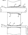
ポストAは、断面が丸く(図1〜8、10〜13)または6角形、正方形(図9)などの多角形であることができる。それは、流体を輸送するまたは銅線や光ファイバ材料などの導体を保護する中空の導管またはパイプであることができる。このポストAは、定位置内に打ち込まれたキーDが接触点でポストAを変形させる、図1のように、わずかに変形可能な材料から作られるのが好ましい。これが、ポストの移動を妨げるのに役立ち、キーを保持するのを助ける。変形可能な材料にはほとんどの金属およびいくつかのプラスチックが含まれるが、選択されるプラスチックが変形圧力のために割れたり機能しなくなったりしないように注意しなければならない。本発明は、ポストをその中に含むことなしに適切に組み立てられそうもないが、ポストそれ自体はこのアンカー留め発明の一部をなさないことに留意されたい。
Post A
The post A can have a round cross section (FIGS. 1-8, 10-13) or a polygon such as a hexagon or a square (FIG. 9). It can be a hollow conduit or pipe that transports fluids or protects conductors such as copper wire or fiber optic materials. The post A is preferably made from a slightly deformable material, as in FIG. 1, where a key D driven into place deforms the post A at the point of contact. This helps prevent the movement of the post and helps hold the key. Deformable materials include most metals and some plastics, but care must be taken that the selected plastic does not crack or fail due to deformation pressure. It should be noted that although the present invention is unlikely to be properly assembled without including a post therein, the post itself does not form part of this anchoring invention.
ハウジングB
これは金属で、ただしプラスチックで作られるのも好ましい、強いかつ耐久性のある、非腐食性材料から作られるのが好ましいシェル(図1の正断面内の濃い斜線B)である。このハウジングBは、通常使用のためにコンクリート内に埋め込まれるであろう。したがって使用のときほとんど圧縮できない囲いがハウジングの外側の周りに設けられている。鋼の補強リング(3)を引っ張り強度を与えるためにコンクリート内に埋め込むことができる。付着性を改善し、かつ非対称的な標識に吹き付ける風によって引き起こされるなどのハウジングの所望されない回転を防止するために、フィンまたは他の突起部をハウジングの外側表面に使用することができる。ハウジングの内部には、以下で説明するコレットCの外側上のものと密接に対応するテーパの付いた部分T1およびT2が設けられ、故に適度に正確な形状であるべきである。鋳造金属で作られる場合は、このテーパの付いた領域は、切削または研磨操作で仕上げられるのが有益である可能性がある。テーパの1つの利点は、幅に関していくらかの実用的な公差が存在することである。ハウジングの内側表面に2つ以上の垂直リブYを設けることができ、それらはコレットCを案内し、かつコレットCをハウジング内の回転に抗して把持する。ハウジングの頂端部のところに、外向きに突起するカラーLが設けられる。カラーLの内側表面は、水平のリブZが設けられるのが好ましく、使用時にはそれらはハウジングとコレットCのヘッドの間の隙間を維持し、以下で説明するようにその中に取り外し工具を導入することができる。ハウジングの脚または底端部のところに、好ましくは突き出し型式の線開口部Mを設けることができ、それによってパイプまたは線をコレットCの下でハウジングのベース内に導入することができる。このハウジングの寸法は通常、用途に応じて深さ30cm×直径12〜15cmである。このハウジングの内部も、キー案内部を含むことができる(後ろを参照)。
Housing B
This is a shell made of a strong but durable, non-corrosive material, preferably made of metal, but also of plastic (dark slash B in the normal section of FIG. 1). This housing B will be embedded in concrete for normal use. Thus, an enclosure that is hardly compressible in use is provided around the outside of the housing. A steel reinforcement ring (3) can be embedded in the concrete to provide tensile strength. Fins or other protrusions can be used on the outer surface of the housing to improve adhesion and prevent undesired rotation of the housing, such as caused by wind blowing against asymmetric signs. The interior of the housing is provided with tapered portions T1 and T2, which closely correspond to those on the outside of the collet C described below, and therefore should be reasonably accurate. When made of cast metal, this tapered area may be beneficially finished with a cutting or polishing operation. One advantage of the taper is that there is some practical tolerance for width. There can be two or more vertical ribs Y on the inner surface of the housing, which guide the collet C and grip the collet C against rotation within the housing. A collar L projecting outward is provided at the top end of the housing. The inner surface of the collar L is preferably provided with horizontal ribs Z, which in use maintain a gap between the housing and the head of the collet C and introduce a removal tool therein as described below. be able to. At the leg or bottom end of the housing, preferably a protruding type of line opening M can be provided, whereby a pipe or line can be introduced under the collet C into the base of the housing. The dimensions of this housing are typically 30 cm deep x 12-15 cm in diameter depending on the application. The interior of this housing can also include a key guide (see back).
コレットC
コレットCは、テーパの付いたコレットをテーパの付いた穴に押し込むことによって達成される固定方法で工具を把持するためのエンジニアリングで使用されるコレットと違った形状のくさびである。この基本的なコレットは平面図を見れば分かるように、内向き表面Jが全体的にポストAの外側に合致するような形状にされ、多分ポストA周りの1/3円または半円を備え、ポストをコレットの上側および下側部分のところで固定して掴むためにポストAに対して弾性的に変形する、かつ/またはポストA内に圧入するように、内向き表面Jの上側および下側部分のところに水平リブGを有するのが好ましい。外向きの表面Hは、上側および下側のテーパの付いた領域T1およびT2の角度に注意して、ハウジングBの内壁に合致する。個別のコレットを、ポストの異なるサイズおよび形状に対して、かつより少ないハウジングの種類に対して用意することができる。図3dおよび13dに示すように、適切な形状のコレットを使用して、正方形のくいをこのシステムで丸い穴内に嵌合させることができる。コレットCのヘッドKは、ハウジングBのカラーL内に嵌合するような形状にされかつ寸法設定される、外向きに突起するフランジを備える。ヘッドKの上側表面K1は、外側縁部に向かってわずかに下向きに傾斜の付いているのが好ましく、使用時にコレットCを定位置に駆動するように打ち込むことができる表面を提供する。
Collet C
Collet C is a wedge shaped differently than the collet used in engineering to hold the tool in a fixed manner achieved by pushing the tapered collet into the tapered hole. This basic collet is shaped so that the inwardly facing surface J generally matches the outside of the post A, as can be seen in the plan view, possibly with a 1/3 circle or semicircle around the post A The upper and lower sides of the inwardly facing surface J so as to be elastically deformed with respect to the post A and / or press fit into the post A in order to fix and grip the post at the upper and lower parts of the collet It is preferable to have a horizontal rib G at the part. The outward surface H matches the inner wall of the housing B, paying attention to the angles of the upper and lower tapered regions T1 and T2. Individual collets can be provided for different post sizes and shapes and for fewer housing types. As shown in FIGS. 3d and 13d, a square pile can be fitted into a round hole with this system using a suitably shaped collet. The head K of the collet C includes an outwardly projecting flange that is shaped and dimensioned to fit within the collar L of the housing B. The upper surface K1 of the head K is preferably sloped slightly downward toward the outer edge, providing a surface that can be driven to drive the collet C into place during use.
ハウジングBおよびコレットCの並置可能なテーパの付いたゾーン(T1およびT2)は、コレットに下向きの力が加えられるときポールおよびコレットを定位置にくさび留めする役割を果たす。かなりのテーパの付いた領域を共に有する上側および下側テーパの使用は、把持される品物が任意の高い点またはアンカーの真ん中高めの部分の妨害物に対して行ったり来たり揺れることができないので、より安定な搭載を作り出す傾向にある。勿論、テーパ間の長さは、両方のテーパがポールを定位置に把持するために協働するように良く制御しなければならない。連続するテーパで同様な圧力が支持領域をすぐ介して加えられるであろうが、中央のあたりで揺れることによって本発明の固定システムが振動および曲がりを受け易くさせるであろう。 The juxtaposed tapered zones (T1 and T2) of housing B and collet C serve to wedge the pole and collet in place when a downward force is applied to the collet. The use of an upper and lower taper that have both significant taper areas allows the item being gripped to swing back and forth against any high point or obstruction at the middle high part of the anchor. , Tend to create a more stable mounting. Of course, the length between the tapers must be well controlled so that both tapers cooperate to hold the pole in place. A similar taper with a continuous taper will be applied immediately through the support area, but swinging around the center will make the locking system of the present invention susceptible to vibration and bending.
コレット用の適切な材料には鋳造または圧延できる金属が含まれるが、より好ましくは、例えば射出成型によって製造することができる、例えばポリプロピレンおよび高密度ポリエチレンを含む頑丈なプラスチック材料である。この材料はわずかに曲がることができるので、上記で説明した2つのテーパの付いたゾーンとの組み合わせで利点をもたらす。コレットを取り外すとき、頂部のテーパの付いたゾーンT1はコレットの頂部に加えられる梃子作用で引っ張って自由にすることができるが、もう1つのゾーンT2はくさびの掛かったままである。中間領域は引き伸ばされる。次いでこの引っ張り力が第2のゾーンT2に、それをやはり解放するように伝達される。コレットが柔軟性のない材料から形成された場合、あるいはこのテーパがコレットの全長に沿って連続して延びた場合、コレットのくさびで留められる区画全体を一度に自由にするためにずっと大きな引張力が必要とされるであろう。 Suitable materials for the collet include metals that can be cast or rolled, but more preferably are rugged plastic materials including, for example, polypropylene and high density polyethylene, which can be manufactured, for example, by injection molding. This material can be bent slightly, thus providing an advantage in combination with the two tapered zones described above. When the collet is removed, the top tapered zone T1 can be freed by pulling with the lever action applied to the top of the collet, while the other zone T2 remains wedged. The middle region is stretched. This pulling force is then transmitted to the second zone T2 so as to also release it. If the collet is formed from an inflexible material, or if this taper extends continuously along the entire length of the collet, a much greater tensile force to free the entire collet wedged section at once Will be needed.
各プラスチック材料は、それ固有の収縮特性を有する。コレットは、より安いプラスチックを使用することによってそのコストは軽減されるであろうが、ダイからの解放後に起きるなどのプラスチックによって決まる収縮の知られた結果が引き続く仕上げ動作を必要としないように、単一の成型動作で製造されるのが好ましい。NC機械による切断、研磨および非常に高温の型による短時間焼尽接触が後仕上げに対して可能な技術である。関連する分野で知られているように、冷却特性で役立つように仕上げられる物品の全ての部品が同じ厚さで作られるのが好ましい。 Each plastic material has its own shrinkage characteristics. Collets will be reduced in cost by using cheaper plastics, but the known consequences of shrinkage determined by plastics, such as occurring after release from the die, do not require subsequent finishing operations. It is preferably manufactured in a single molding operation. This is a technique that enables cutting, polishing by NC machine, and short-time burn-out contact with a very high temperature mold for post finishing. As is known in the relevant field, it is preferred that all parts of the article to be finished to serve cooling properties are made with the same thickness.
コレットCは、以下で説明するように、図3bおよび3cに示すようなスロットWまたはRを有する固定装置に対応するように改変することができる。 The collet C can be modified to accommodate a fixation device having a slot W or R as shown in FIGS. 3b and 3c, as described below.
キーD
特に図4に示すように、キーDは(キーが定位置に打ち込まれ、次いで使用後定位置から梃子作用で取り出すことができるようになされた)ヘッドD1、およびキーもくさび形状になるように下側端部に向かってテーパの付いた、(ポストAを保持するためにポストAにしっかりと押し付けられるようになされた)ブレードD2を有する。それは、多分打ち抜かれるまたはそうではなく切断される、軟鋼から作ることができる。このキーは、図3aを見れば分かるように、コレット内に切られた溝Wを下降し、ポストAとハウジングBの間にくさび留めされる。このキーは図4に特に示すように、パイプ内に切り込みかつパイプを変形させ、丸いポストの曲線上により確実な把持動作をもたらすことができる、2つの平行な鋭い縁部を有するように、ポストを圧すための凹んだV字形カットの内側縁部Nを有するべきである。
Key D
In particular, as shown in FIG. 4, the key D is such that the key D is also wedge-shaped (the key is driven into a fixed position and then can be removed from the fixed position after use by lever action), and the key is also wedge-shaped. It has a blade D2 that is tapered towards the lower end (so that it can be pressed firmly against post A to hold post A). It can be made from mild steel, possibly stamped or otherwise cut. This key is lowered between the groove W cut in the collet and wedged between the post A and the housing B, as can be seen in FIG. This key has two parallel sharp edges that can cut into the pipe and deform the pipe, resulting in a more positive gripping action on the round post curve, as specifically shown in FIG. Should have a concave V-shaped inner edge N for pressing.
このポストは回転すること、または右に左に揺れ次いで搭載部から抜け出すことを防止すべきである。図4bは、内側でポストAと外側でハウジングBと両方に係合する、コレットCのスロットW内へのキーDの配置を示す。キーDを押し付けることができる金属板EをハウジングBに設けるのが好ましい。これは平らな板を備えることができ、あるいは、通常50mm×75mmであり1.2mm厚さの亜鉛めっき鋼から作られ、かつ曲げられかつキーDが滑り落ちることができるキーと相性のよいスロットE1の両側を画成する2つのリッジE2を含むように折り曲げられている、図4に示すような成型金属板を備えることができる。この板Eがハウジングを取り囲むコンクリート(2)に押し付けられるように、この板Eは、キーDが下方に打ち込まれる、ハウジングBを貫通して切られるスロットの後方に、ハウジングBの外側表面上に搭載されるのが好ましい。このコンクリートは、この種の使用が引張力を加えるので、(図1の鋼リングによってなど)補強されるのが好ましい可能性がある。この手段によって内側縁部Nが、ポストAをコレットCまたはハウジングBに対する回転移動に対して固定するように、内側縁部NがポストAの材料内に圧入され、材料を変形させまたは材料内に切り込むように、キーがスロットW内に下方に打ち込まれるとき、キーDの外側に堅固な支承表面が形成される。 This post should be prevented from rotating or swaying to the right and left and then coming out of the mounting. FIG. 4b shows the arrangement of the key D in the slot W of the collet C which engages both the post A on the inside and the housing B on the outside. It is preferable to provide the housing B with a metal plate E on which the key D can be pressed. This can comprise a flat plate, or it is made of galvanized steel, usually 50 mm x 75 mm and 1.2 mm thick, and is a slot E1 compatible with the key that can be bent and the key D slides down. 4 may be provided which is bent to include two ridges E2 defining both sides of the metal plate. The plate E is placed on the outer surface of the housing B behind the slot cut through the housing B, where the key D is driven downward, so that the plate E is pressed against the concrete (2) surrounding the housing. It is preferable to be mounted. This concrete may be preferably reinforced (such as by the steel ring of FIG. 1) because this type of use applies tensile forces. By this means, the inner edge N is pressed into the material of the post A so that the inner edge N secures the post A against rotational movement relative to the collet C or housing B, causing the material to deform or into the material. A rigid bearing surface is formed on the outside of the key D when the key is driven down into the slot W to cut.
キーの別の型式は、ハウジングが、通常は打ち込みコンクリートである地面材料の内側の周りで回転するのを防止するように設計される。図4cは、上方からのハウジングの図を示し、Lは拡大する最上部部分を示す(図4dの立面図も参照)。図4eは、例えば約幅50mm深さ50mmの、図4cに示すようにLの境界の内側にある一端部のところで上方に曲げられたリップを有する、曲げられた金属キーの斜視図である。ハウジングは、キーE3が両側でコンクリートによって取り囲まれるように、コンクリートがハウジングの周りに注がれる前に行われるキーE3の挿入行為によって設置者が膜を破裂させてしまわない限り、プラスチックの膜を保持する薄いスロットが設けられている。この坑回転キーは、その中央軸に沿ってハウジングの垂直部分の外側を(図1を参照すると、T1のところで)堅固に圧し付けることによって作用する。キーE3の垂直縁部は、回転動作がハウジングLに、そしてキーE3に強制される場合、コンクリート内に切り込む傾向がある。 Another type of key is designed to prevent the housing from rotating around the inside of the ground material, which is usually driven concrete. FIG. 4c shows a view of the housing from above and L shows the top part expanding (see also the elevation view of FIG. 4d). FIG. 4e is a perspective view of a bent metal key having a lip bent upward at one end inside the L boundary as shown in FIG. 4c, for example about 50 mm wide and 50 mm deep. The housing will have a plastic membrane, unless the installer has ruptured the membrane by inserting the key E3 before the concrete is poured around the housing so that the key E3 is surrounded by concrete on both sides. A thin slot is provided for holding. This downhole key works by firmly pressing (at T1, referring to FIG. 1) the outside of the vertical part of the housing along its central axis. The vertical edge of the key E3 tends to cut into the concrete when rotational movement is forced into the housing L and to the key E3.
固定ピンP
図6および7に示すように、ポストAの回転および/またはアンカー留め手段からの離脱防止するための別の手段を設けることができる。ハウジングBの搭載部P1から、または搭載部P1を貫通して内部空洞内に延びる固定ピンPが設けられる。図6および図3cに示すように、コレットCは、固定ピンPがコレットCを貫通してポストAと接触するように固定ピンP上に嵌合することができる、底部から上向きに延びる長手方向のスロットRを設けるように改変することができる。ポストAも、ピンPが通過して入るように適切な高さのところに開口部P2を有するように改変されるのが好ましい。第2のコレットCがまだ定位置にない状態で、ポストAは固定ピンPを通過し摺動することができるように傾けることができる。次いで、ピンPが開口部P2の隣に配置されるとき、ポストAはピンを開口部内に係合するために真直ぐに起こし、次いでアセンブリ全体を定位置に把持するように第2のコレット(図示せず)をもう1つの側面に圧し込むことができる。この手段によって、ポストAはハウジングBに対して回転または長手方向に摺動することが防止される。
Fixing pin P
As shown in FIGS. 6 and 7, another means for preventing the rotation of the post A and / or disengagement from the anchoring means can be provided. A fixing pin P that extends from the mounting portion P1 of the housing B or through the mounting portion P1 into the internal cavity is provided. As shown in FIGS. 6 and 3c, the collet C has a longitudinal direction extending upward from the bottom, which can be fitted onto the fixing pin P such that the fixing pin P penetrates the collet C and contacts the post A It can be modified to provide a slot R. The post A is also preferably modified to have an opening P2 at an appropriate height so that the pin P can pass through. With the second collet C not yet in place, the post A can be tilted so that it can slide past the fixing pin P. Then, when the pin P is placed next to the opening P2, the post A raises straight to engage the pin into the opening and then the second collet (FIG. (Not shown) can be pressed into the other side. By this means, the post A is prevented from rotating or sliding in the longitudinal direction with respect to the housing B.
コレットの取り外し
コレットの取り外しに使用するための梃子の2つの形態が図7および図8に示されている。この形態は通常の工具にめったに見られないものであることは理解されるであろう。例えば、ネジ回しはこのコレットのヘッドの下で有用な手掛かりを全く有さないであろう。この梃子は、これを持たない人はポストを取り外すのが非常に困難であることが分かるであろう点で一種の安全対策である。この梃子は、使用者が適切な量の梃子比を有するように使い易い長さ(30〜50cm)のシャフトと、一端部から横向きに延びるような形状のヘッドを有する。図8に示すように、この工具のヘッドは、全体的に三日月形状のヘッドUおよび支点Xを備える。使用時には、ヘッドUの先端部U1がコレットのヘッドKの下に挿入され、ハウジングBのカラーLを押し付ける、かつ/または取り囲むコンクリート支持層2上の支点Xで梃子作用を行う。カラーLの内側表面上のリッジZが、この工具のヘッドを挿入する目的のための隙間がフランジKの下に残るのを確実にする。このヘッドUは、コレットCがキーDと独立に取り外すことができるように、キーDの周りに嵌合するための凹部U3を組み込むことができる。
Collet Removal Two forms of insulators for use in collet removal are shown in FIGS. It will be appreciated that this configuration is rarely seen in normal tools. For example, a screwdriver will have no clues useful under this collet head. This insulator is a kind of safety measure in that a person without it will find it very difficult to remove the post. The lever has a shaft (30-50 cm) that is easy to use so that the user has an appropriate amount of lever ratio, and a head shaped to extend laterally from one end. As shown in FIG. 8, the head of this tool includes a crescent-shaped head U and a fulcrum X as a whole. In use, the tip U1 of the head U is inserted under the head K of the collet and acts as a fulcrum at the fulcrum X on the concrete support layer 2 that presses and / or surrounds the collar L of the housing B. A ridge Z on the inner surface of the collar L ensures that a gap remains under the flange K for the purpose of inserting the tool head. This head U can incorporate a recess U3 for fitting around the key D so that the collet C can be removed independently of the key D.
工具Vは、支点XがハウジングBそれ自体ではなく、ハウジングBが搭載される支持層2を押し付けるであろうように形成され、配置されるのが好ましい。しばしば空気隙間が注がれたコンクリートの上方で、かつハウジングBのカラーLの下方に捕らわれ、支持層材料の支持なしではカラーLは支点Xの圧力に耐えるのに弱すぎる可能性がある。したがって、支点XとカラーLの間に置くための別個の支承板Yを設けることができ、かつ/またはヘッドUを支点Xに対して枢動的に搭載し(図7のU2)、支点がハウジングBの外側の支持層(2)の上側表面にある間に、カラーLのフランジKの下に嵌合するように配置することができる。 The tool V is preferably formed and arranged so that the fulcrum X will press the support layer 2 on which the housing B is mounted, not the housing B itself. Often trapped above the concrete into which the air gap is poured and below the collar L of the housing B, without the support of the support layer material, the collar L may be too weak to withstand the pressure at the fulcrum X. Accordingly, a separate bearing plate Y can be provided for placement between the fulcrum X and the collar L and / or the head U is pivotally mounted with respect to the fulcrum X (U2 in FIG. 7). While on the upper surface of the outer support layer (2) of the housing B, it can be arranged to fit under the flange K of the collar L.
工具の形状は例えば特定の用途Nに使用されるコレットCの寸法および形状に適合するように改変することができ、このシステムが(以下で説明するように)正方形断面のポストを搭載するために正方形の形態で適用される場合は、コレット取り外し工具Vは、上記で説明した三日月形状のヘッドUではなく、直線のまたはV字形状のヘッドUを有するであろうことは理解されるであろう。 The shape of the tool can be modified to fit, for example, the size and shape of the collet C used for a particular application N, so that the system can be mounted with a square section post (as described below). It will be appreciated that when applied in the form of a square, the collet removal tool V will have a straight or V-shaped head U rather than the crescent-shaped head U described above. .
別の取り外し手順
同じまたは類似の工具V2をキーDを抽出するために使用することができるのは理解されるであろう。例えばコレットのヘッドK内のネジ切りされた開口部を貫通して垂直に下方に通過しカラーL上の板を押し付け、図12に示すように回すときコレットを上昇させることができるネジなどの他の手段をコレットをハウジングから抽出するために使用が可能であることも理解されるであろう。図12は、コレットベースのポストアンカー用の押さえつけ、および取り外し装置としての機械ネジの使用を示す。これは、機械的な利点を含む挿入または取り外しを可能にする代替の方法である。ポストはA、コレットハウジングはB、2つのコレットはCとしてポストの各側面に示されており、Lはハウジングの表面拡大の外側縁部を示す。ボルト1201は、ソケットスパナと係合され得る駆動可能なヘッド、あるいは許可を得ていない取り外しを防止するために使用が可能である何らかの「安全対策ヘッド」を有する。ボルトシャフトは、コレットの一部をなすワッシャー1202に対して回すことができる、引き続き取り付けられる固定ワッシャー1203を含む。ボルトのシャフトは、固定ナット1204を通過する従来型のネジ1205を含む。このネジは、空間1206内ではそうではなく自由に回る。ボルトヘッドが回されるとき、ボルトは固定ナットとの係合によってハウジング内に引き下ろされるか、反対方向に回される場合はコレットワッシャー1202に対して回転し、コレットが強制的にハウジングから引き出され、それによってポストがアンカーBから自由になるようにボルトをハウジングから外に上昇させるかのいずれかである。1207は、ボルト1201を含むこの型式のコレットの斜視図である。前に説明した伸張効果は依然として適用可能である。
Alternative Removal Procedure It will be appreciated that the same or similar tool V2 can be used to extract the key D. For example, a screw that passes through a threaded opening in the head K of the collet, passes vertically downward, presses the plate on the collar L, and can lift the collet when turned as shown in FIG. It will also be appreciated that these means can be used to extract the collet from the housing. FIG. 12 shows the use of a machine screw as a hold-down and removal device for a collet-based post anchor. This is an alternative method that allows insertion or removal including mechanical advantages. The post is shown as A, the collet housing is B, the two collets are shown as C on each side of the post, and L is the outer edge of the housing surface enlargement. Bolt 1201 has a drivable head that can be engaged with a socket spanner, or some “safety head” that can be used to prevent unauthorized removal. The bolt shaft includes a subsequently attached
キャップおよびカバー
射出成型キャップ(図2のF2)は、ポストが定位置にないとき使用するための任意選択の付属品として入手可能である。この表面は、図5aに示すように半円形ではなく平らであることができる。このぴったり嵌合するキャップは、ゴミを入らせないように、かつ人々または動物への怪我を防止するために穴の上に配置することができる。弾力性のある部品またはある形態の係合可能な留め金(ネジまたはバイオネット留め具〜図示せず)、または(「熱接着(hot glue)」樹脂などの)一時的な接着剤さえもキャップを保持するために使用することができる。我々は、ハウジングの穴内にネジ型式の留め具を使用して、キャップを定位置にねじ込むのを好む。ぴったり嵌合するキャップを取り外すために、我々は、(a)固定ネジを取り外し、次いで(b)より大きなネジをキャップの対応する穴内にネジ込み、次いで(c)プライヤー等でキャップを引っ張るための梃子装置としてそれらのネジを使用するステップを勧める。このキャップは、空のスリーブに対する突発的な損傷を防止するためにも有用である。
Cap and Cover An injection molded cap (F2 in FIG. 2) is available as an optional accessory for use when the post is not in place. This surface can be flat rather than semicircular as shown in FIG. 5a. This close-fitting cap can be placed over the hole to keep dirt out and to prevent injury to people or animals. Caps with elastic parts or some form of engageable clasps (screw or bayonet fasteners not shown) or even temporary adhesives (such as “hot glue” resin) Can be used to hold We prefer to screw the cap into place using screw type fasteners in the holes in the housing. To remove the tight-fitting cap, we will (a) remove the fixing screw, then (b) screw a larger screw into the corresponding hole in the cap, and then (c) pull the cap with a pliers etc. The step of using those screws as a lever device is recommended. This cap is also useful to prevent accidental damage to the empty sleeve.
異なる断面形状
図13は、如何に本発明が、コレットの使用の有用な結果、すなわち、コレットが空間を詰めることができるような形状にすることができ、(複数のテーパが付いているけれども横断面で)通常は円筒形の空洞と非円形の横断面を有するポールとの間のアダプタとして役立つこと、を活用するかを示す。全ての場合で、コレットの外側外形は前に説明し、例えば図3a〜3dに、「H」と印の付けられた平行な壁区画によって分離される、テーパT1(約2.5度の傾斜の上側テーパ)およびT2と同じ傾斜の下側テーパとして示されているようなものである。図13aは、どのように6角形の断面を収容することができるかを示す。1300は、使用のとき土壌またはコンクリート等に対して配置すべきシェルの壁である。1301は、例えば、一般に街路照明用途のために全体的にテーパの付いた圧延薄板から作られ供給される6角形のポールの外形である。斜線の引いた外形1302は、1つの半円コレットの一例であり、斜線の引いた外形1303は、異なるコレット外形の一例である。これら2つの型式は同時に使用することができ、または一時にただ1つの(いずれかの)型式として使用することができる。
Different Cross-sectional Shapes FIG. 13 illustrates how the present invention can be shaped as a useful result of the use of a collet, ie, the collet can fill the space (multiple tapered but transverse Shows how to utilize (usually) serving as an adapter between a cylindrical cavity and a pole with a non-circular cross-section. In all cases, the outer contour of the collet is described earlier, for example, in FIGS. 3a-3d, a taper T1 (approximately 2.5 degree slope) separated by parallel wall sections marked “H”. And the lower taper of the same slope as T2. FIG. 13a shows how a hexagonal cross section can be accommodated.
図13bも、どのように6角形断面のポールを収容することができるかを示す。1300は、土壌またはコンクリート等に対して配置されるシェルの壁である。1301は、例えば、街路照明用途のために全体的にテーパの付いた圧延薄板等で一般に供給される6角形のポールの外形である。斜線の引いた外形1304は、1つの120度コレットの一例であり、斜線の引いた外形1304b1および1304b2は、さらに別の、60度コレットの外形の一例である。これら2つの型式は同時に使用することができ、または一時にただ1つの(いずれかの)型式として使用することができる。図13cは、10の側壁のポールの外形を1306として示す。1307は、外形で示す4つの36度コレットのうちの1つであり、1308は代替の、ポールの外側の2つの小面の周りを延びる72度のコレットである。図13dは、どのように正方形ポールが、コレット断面の少なくとも2つの変形体1310および1311を使用して、丸い開口部1300内にしっかりと嵌合することができるかを示す。逆の配置は図13eに示され、正方形断面の外側パイプ1312に、円形断面のポール1315の周りをクランプする(2つの様式が示されている)コレット1313または1314が設けられる。最後に、図13fは、コレットが完全に適用可能であることを示す。非対称形の「U」字形ポストが、1つの変則的なコレット(1317)と(1310または1311と五十歩百歩である)外形1318の2つで定位置に把持される。全てのこれらの例示的な横断面は代表であり、使用される可能性のあるあり得る変形形態を決して限定しない。
FIG. 13b also shows how a hexagonal cross section pole can be accommodated.
変形形態
正方形フェンスポスト
図9は、どのように本発明の部品が、形体が重要なフェンスの使用に一般に好まれる正方形形状のポストに適用できるかを示す。図9aは、正方形ポストAの周りの正方形にされたハウジングBを示す平面図であり、図9bは断面正面図である。2つの正方形のコレットC(斜視図に対して9c参照)が、このポストを定位置に把持する。2つのコレットが、別の位置はフェンス材料の後ろにありアクセスするのが困難である可能性があるので、それらがフェンスの一方の側からアクセス可能であるようにポストの同じ側に使用される。Qはカバーを固定するのに使用されるネジ穴である。このシステムはポスト壁がフェンスの長さと一直線に向けられていることに留意されたい。ここで示されるコレットでは、ハウジングBのカラーL内で適切な形状の工具でアクセスすることができる梃子スロットK2がコレットのヘッドK内に設けられる。
Variations Square Fence Post FIG. 9 illustrates how the components of the present invention can be applied to square shaped posts where the configuration is generally preferred for use in critical fences. 9a is a plan view showing a squared housing B around a square post A, and FIG. 9b is a cross-sectional front view. Two square collets C (see 9c for perspective view) hold the post in place. Two collets are used on the same side of the post so that they are accessible from one side of the fence as another location is behind the fence material and may be difficult to access . Q is a screw hole used to fix the cover. Note that this system has the post wall oriented in line with the length of the fence. In the collet shown here, a lever slot K2 is provided in the head K of the collet that can be accessed within the collar L of the housing B with a suitably shaped tool.
壊れやすいポスト
ポストを立てることができるが、(スタジアムを緊急に空にする間などの)圧力が大きくなりすぎた場合、ポストが安全な方法で崩壊するのが望ましい、群衆整理などのいくつかの用途が存在する。(例えば)パニックの群衆がポストを踏み倒した場合、その後で人が突起する柱の上で怪我をしないように、過剰に応力が掛かったとき地面レベルに手際よく折れるポストを上記のアンカー留めシステムで使用するために設けることができる。後で、壊れたベースは引き抜くことができ、ポスト全体は、例えば新たなコンクリートを注ぐことなしに安価に交換することができる。路側の標識も、車両によって衝突される場合、安全な形態に壊れるべきである。
Fragile post Posts can be raised, but if the pressure becomes too high (such as during an emergency empty stadium), it is desirable that the post collapse in a safe manner, such as crowd control There are uses. (For example) if the panic crowd stepped over the post, the anchoring system above would allow the post to break well to the ground level when overstressed so that the person would not be injured on the protruding pillar. Can be provided for use. Later, the broken base can be withdrawn and the entire post can be replaced inexpensively, for example, without pouring new concrete. Roadside signs should also break into a safe form when impacted by a vehicle.
電気経路設定
図1は、どのように本発明の部品が、照明、電話、交通照明、拡声器等のための電線を中空のポストの内部に運び込むために適用することができるかを示す。ケーブル(図2も参照)は地中に埋められており、その線をポストのベースのところの開口部Mを通り供給する。開口部Mは、ハウジングB内に事前形成され、または別法として、線または連結パイプの挿入のために容易に穴あけすることができるが、穴あけされないとき防水シールとして役立つ、案内リムを有する壊れ易い膜として設けることができる。
Electrical Routing FIG. 1 shows how the components of the present invention can be applied to carry wires for lighting, telephones, traffic lighting, loudspeakers, etc. into the interior of a hollow post. The cable (see also FIG. 2) is buried in the ground and feeds the wire through an opening M at the base of the post. The opening M is pre-formed in the housing B, or alternatively can be easily drilled for insertion of a wire or connecting pipe, but is fragile with a guide rim that serves as a waterproof seal when not drilled It can be provided as a film.
水等を搬送するパイプの支持体
本発明が、垂直の代わりに水平に適用される、上記で説明したアンカー留め手段を使用して壁を貫通する、または壁内を通るパイプまたは他の細長い部材を定位置に脱着可能に固定するための装置および方法を提供することは理解されるであろう。
Supports for pipes carrying water etc. The present invention is applied horizontally instead of vertically, pipes or other elongated members that penetrate or pass through walls using the anchoring means described above It will be appreciated that an apparatus and method for removably securing a device in place is provided.
図10は、どのように本発明の部品が、壁を貫通する送水管などの流体を搬送するために適用することができるかを示す。大きなパイプがA2として示されている。それが壁内の穴を通過するとき、パイプは、(自由端からパイプの上を滑らせて、または1対のシェルとして設けられるのいずれかの)ハウジングBによって取り囲まれ、このパイプはコレットCを使用して定位置にクランプされる。図10の上側部分は、単一の端部を有するコレットアセンブリを示し、下側部分は、ガスパイプまたは送水管A3などのより小さなパイプの周りの2重アセンブリを示す。我々はこの変形形態が、他にも利点はあるが、パイプに沿って移動する音がコレットのところで、(鉛でよく知られているように)ヒステリシスおよび質量の特性、したがって音の吸収に起因して少なくとも部分的に弱められる利点を提供することを見出した。それは地面の移動または地震が万一起きた場合、コレット内でパイプが摺動するのを可能にすることができる緊密さのレベルで設定することができる。 FIG. 10 shows how the components of the present invention can be applied to carry fluids such as water pipes that penetrate walls. A large pipe is shown as A2. When it passes through a hole in the wall, the pipe is surrounded by a housing B (either sliding over the pipe from the free end or provided as a pair of shells), this pipe being collet C To be clamped in place. The upper part of FIG. 10 shows a collet assembly with a single end and the lower part shows a double assembly around a smaller pipe, such as a gas pipe or a water pipe A3. We have this advantage, but there are other advantages, too, because the sound moving along the pipe is at the collet (as is well known for lead) due to hysteresis and mass properties and hence sound absorption. We have found that it offers the advantage of being at least partially weakened. It can be set at a level of tightness that can allow the pipe to slide in the collet in the event of a ground movement or earthquake.
壁内への手すりのアンカー留め
上記のような方法は、手すりの端部をレンガまたはコンクリートなどで造られた壁内にアンカー留めするのに使用することができる。
Anchoring a handrail into a wall The method as described above can be used to anchor the end of a handrail into a wall made of brick or concrete or the like.
パイプ間の端部と端部をつき合わせた水密継ぎ手
図11は、このコレット/ハウジングアセンブリをどのように、ほんのわずかな改変される形態でパイプ間の連結部として使用が可能であるかを示す。このアセンブリは、例えば、地面内または壁内に搭載されるべき必要性は全くない。それは自立型であることができる。このパイプの内腔をA4のところに示す。改変されたハウジングB4がパイプのほぼ面一の端部の周りに完全なリングを形成する。このハウジングは、パイプ外側と近似の接触を行う内部フランジを含む。シールは、均圧化リングC1に対して加えられ、それが順次、シール接触に強制的に入れられるOリングC2を圧す、コレットCのベースによって加えられる圧力を使用してもたらされる。そのようなOリングが1つずつ各側に使用される。このコレットアセンブリが組み立てられ、キーによって定位置に把持されるとき、緊密なシールがパイプの両端部のところに溶接等を使用することなしに設けられる。この着想は、異なる直径を有するパイプを合致させるために使用することができ、(例えば)軍事キャンプおよび屋外市を催す場所などの再建設可能な、一時的な配管に使用することができる。
Figure 11 shows how this collet / housing assembly can be used as a connection between pipes in a slightly modified form. . There is no need for this assembly to be mounted, for example, in the ground or in a wall. It can be free standing. The lumen of this pipe is shown at A4. The modified housing B4 forms a complete ring around the substantially flush end of the pipe. The housing includes an internal flange that makes approximate contact with the outside of the pipe. The seal is applied using the pressure applied by the base of the collet C, which is applied against the pressure equalizing ring C1, which in turn presses the O-ring C2 forced into the seal contact. One such O-ring is used on each side one by one. When this collet assembly is assembled and held in place by the key, a tight seal is provided at the ends of the pipe without using welding or the like. This idea can be used to match pipes with different diameters, and can be used for reconstructable, temporary plumbing such as places hosting military camps and outdoor cities (for example).
農場フェンスおよび囲い地
フェンス、仕切り枠(bail)、排水溝(race)としての役割を果たすコンクリート床および亜鉛めっき鉄配管は、ニュージーランドで少なくとも動物囲い地、牛舎として、他の国では家畜を収容するための畜舎として広く使用される。パイプが直接コンクリート内に設置されるとき、濡れたコンクリートは適度に良好な導電体であるため電解電池での腐食が生じる可能性があり、パイプはあちこち移動させることができなくなる。本発明の1つの用途は、いくつかのパイプがステンレス鋼のものであり、その他が亜鉛めっき鉄のものである場合でさえ、腐食を最小限にし、損傷なしに配管のレイアウトを時々変更することができるパイプ用の非電導性ソケットを提供することである。
Farm Fences and Enclosures Concrete floors and galvanized iron pipes that serve as fences, bail, races, at least as animal enclosures and barns in New Zealand and livestock in other countries Widely used as a livestock barn. When the pipe is installed directly in the concrete, the wet concrete is a reasonably good conductor, which can cause corrosion in the electrolytic cell and the pipe cannot be moved around. One application of the present invention is to minimize corrosion and sometimes change piping layout without damage, even when some pipes are of stainless steel and others are of galvanized iron. It is to provide a non-conductive socket for a pipe that can be used.
産業上の利用可能性および利点
本発明を地面内にポストの可逆的な、かつ確実なアンカー留めを提供する手段として考えるとき、用途には、
一時的な表示および広告標識、
一時的な、容易に復元される脱着可能なガードレール、フェンス、交通機関または群衆整理ポストまたは支持体
所与のスポーツコードが「シーズン中」であるときの、特定の位置のところのゴールポストのためなどのスポーツまたは運動場の取り付け器具、およびそうではなく覆いによる交換、
時々再構成が可能な、地面から外に上昇する垂直パイプに基づく種類のものなどの運動場の取付具、
許可された車両以外の全てによる空間への車両アクセスを防止すること、
非常に寒い季節中の果樹園などに一時的な灌漑ステーションを設けること、
地面内に掘られない一時的な囲い地に「取って代わり」そうな、特に牛または鹿などのより荒々しい動物用の、農場用の脱着可能な貯蔵場所を設けること、が含まれる。
Industrial Applicability and Benefits When considering the present invention as a means of providing reversible and secure anchoring of posts in the ground, applications include
Temporary display and advertising signs,
Temporary, easily restored removable guardrails, fences, transportation or crowd control posts or supports For goal posts at specific locations when a given sport code is "in season" Sports or playground mounting equipment such as, and replacement by cover instead
Playground fixtures, such as those based on vertical pipes rising out of the ground, which can be reconfigured from time to time
Prevent vehicle access to space by all but authorized vehicles,
Providing temporary irrigation stations in orchards during very cold seasons,
Including providing a detachable storage area for farms, especially for more harsh animals such as cows or deers that are likely to "replace" temporary enclosures that are not dug into the ground.
最後に、本明細書で説明されかつ/または図示されたような本発明の範囲は、特定の実施形態に限定されないことは理解されるであろう。当業者は、記載の本発明の範囲および趣旨から逸脱することなく、様々な改変形態、追加、知られた均等物、および代替物が可能であることを理解するであろう。 Finally, it will be understood that the scope of the invention as described and / or illustrated herein is not limited to a particular embodiment. Those skilled in the art will appreciate that various modifications, additions, known equivalents, and alternatives are possible without departing from the scope and spirit of the described invention.
A ポスト
B ハウジング
C コレット
D キー
D1 キーのヘッド
D2 キーのブレード
E 金属板
E1 金属板のスロット
E2 金属板のリッジ
E3 キー
F2 キャップ
G 水平リブ
J 内側表面
K ヘッド、フランジ
K1 ヘッドKの上側表面
L カラー
M 線開口部
N 内側縁部
P 固定ピン
P2 開口部
R スロット
T1、T2 テーパの付いた部分
U 三日月形状のヘッド
U1 先端部
U3 凹部
V 工具
V2 工具
W スロット
X 支点
Y 垂直リブ、支承板
Z 水平リブ、リッジ
2 支持層
3 補強リング
1201 ボルト
1202 ワッシャー
1203 固定ワッシャー
1204 ナット
1205 ネジ
1206 空間
1300 シェル壁
1301 6角形ポールの外形
1302 半円コレット
1303 コレット外形
A Post B Housing C Collet D Key D1 Key Head D2 Key Blade E Metal Plate E1 Metal Plate Slot E2 Metal Plate Ridge E3 Key F2 Cap G Horizontal Rib J Inner Surface K Head, Flange K1 Head K Upper Surface L Collar M Line opening N Inner edge P Fixing pin P2 Opening R Slot T1, T2 Tapered part U Crescent head U1 Tip U3 Recess V Tool V2 Tool W Slot X Support point Y Vertical rib, Support plate Z Horizontal rib, ridge 2 Support layer 3 Reinforcement ring 1201
Claims (19)
前記脚の断面に沿って、かつ断面の周りに嵌合するような形状にされた内向きの面を有する少なくとも1つの細長いコレットと、
前記少なくとも1つのコレットと前記脚とを組み合わせて収容するような形状にされ、寸法設定される内部空洞を有する細長いハウジングと、を備え、
前記少なくとも1つのコレットのそれぞれが、頂端部および底端部を有し、前記頂端部および前記底端部は、前記ハウジング内の前記内部空洞の頂端付近および底端付近にそれぞれ位置するように離間しており、前記頂端部から内向きにテーパの付いた外向きの面が、前記頂端部に近接する第1の部分と前記底端部に近接する第2の部分とにおいて前記底端部に向かっており、
前記ハウジングの前記内部空洞には、対応する前記第1と第2の部分とにおいて内向きにテーパが付いており、
前記コレットのそれぞれの前記外向きの面には、前記第1のテーパの付いた部分と前記第2のテーパの付いた部分との間でテーパが付いておらず、
それによって使用時に前記コレット上の下向きの圧力が前記頂端部付近および前記底端部付近で前記外向きの面と前記ハウジングとの間にくさび留め接触を作り出すことができ、前記第1のテーパの付いた部分と前記第2のテーパの付いた部分の間では、前記コレットと前記ハウジングの間にくさび留め接触が実質的に起きないことを特徴とするアンカー。An anchor for fastening an elongate member in a support layer, the elongate member having legs of a substantially constant cross section, the anchor comprising:
At least one elongated collet having an inwardly-facing surface configured to fit along and around the cross-section of the leg;
An elongated housing having an internal cavity shaped and dimensioned to receive a combination of the at least one collet and the leg;
Each of the at least one collet has a top end and a bottom end, the top end and the bottom end being spaced apart so as to be located near the top end and the bottom end of the internal cavity in the housing, respectively. An outwardly tapered surface that tapers inwardly from the top end at the bottom end in a first portion proximate to the top end and a second portion proximate to the bottom end. Heading,
The internal cavity of the housing is tapered inwardly in the corresponding first and second portions;
Each outward face of the collet is not tapered between the first tapered portion and the second tapered portion;
Thereby, in use, downward pressure on the collet can create a wedge contact between the outward surface and the housing near the top end and near the bottom end of the first taper. An anchor characterized by substantially no wedge contact between the collet and the housing between the attached portion and the second tapered portion.
前記細長い部材の脚を前記ハウジングの内部空洞内に挿入するステップと、
少なくとも1つの前記コレットを前記脚と並べて前記ハウジングの前記内部空洞内に挿入するステップと、
前記頂端部の近くと前記底端部の近くとで、前記コレットと前記ハウジングの間のくさび留め接触を作り出すように前記少なくとも1つのコレット上に下向きの圧力を加えるステップとを含み、前記第1のテーパの付いた部分と前記第2のテーパの付いた部分の間では、前記コレットと前記ハウジングの間にくさび留め接触が実質的に起きないことを特徴とする請求項1に記載のアンカーを使用して細長い部材を支持層内に締結する方法。Installing the housing in a hole in the support layer using a solidifiable fluid construction material, such as concrete;
Inserting a leg of the elongate member into an internal cavity of the housing;
Inserting at least one of the collets into the internal cavity of the housing alongside the legs;
Applying downward pressure on the at least one collet to create a wedge contact between the collet and the housing near the top end and near the bottom end, The anchor of claim 1 wherein substantially no wedge contact between the collet and the housing occurs between the tapered portion of the second and the second tapered portion. A method of using an elongate member to fasten within a support layer.
前記コレットを通り前記脚と前記ハウジングの間に係合するように、前記キーを前記長手方向スロット内に嵌合させるステップをさらに含む、請求項18に記載の方法。The collet includes a longitudinal slot extending downwardly from the top end, and the anchor further includes a key shaped and dimensioned to fit within the slot;
19. The method of claim 18 , further comprising the step of fitting the key into the longitudinal slot to engage between the leg and the housing through the collet.
Applications Claiming Priority (3)
| Application Number | Priority Date | Filing Date | Title |
|---|---|---|---|
| NZ54390605 | 2005-12-01 | ||
| NZ543906 | 2005-12-01 | ||
| PCT/NZ2006/000314 WO2007064235A1 (en) | 2005-12-01 | 2006-12-01 | Anchoring system for posts |
Publications (2)
| Publication Number | Publication Date |
|---|---|
| JP2009517571A JP2009517571A (en) | 2009-04-30 |
| JP4970463B2 true JP4970463B2 (en) | 2012-07-04 |
Family
ID=38092475
Family Applications (1)
| Application Number | Title | Priority Date | Filing Date |
|---|---|---|---|
| JP2008543226A Active JP4970463B2 (en) | 2005-12-01 | 2006-12-01 | Post anchoring system |
Country Status (11)
| Country | Link |
|---|---|
| US (1) | US7954289B2 (en) |
| EP (1) | EP1960618B1 (en) |
| JP (1) | JP4970463B2 (en) |
| KR (1) | KR101395988B1 (en) |
| CN (1) | CN101351607B (en) |
| AU (1) | AU2006321066B2 (en) |
| HK (1) | HK1127101A1 (en) |
| NZ (1) | NZ569410A (en) |
| RU (1) | RU2398083C2 (en) |
| WO (1) | WO2007064235A1 (en) |
| ZA (1) | ZA200805690B (en) |
Families Citing this family (53)
| Publication number | Priority date | Publication date | Assignee | Title |
|---|---|---|---|---|
| US20090017946A1 (en) * | 2007-07-13 | 2009-01-15 | Sportcraft, Ltd. | Quick set up net assembly for game play |
| GB2454911A (en) * | 2007-11-22 | 2009-05-27 | Jonathan Edward Browning | Dual sleeve post socket |
| AU2008255268B2 (en) * | 2007-12-21 | 2010-11-25 | Illinois Tool Works Inc. | Cast-in insert |
| US8011149B2 (en) | 2008-06-27 | 2011-09-06 | Knudsen N Eric | Post sleeve assembly |
| US7861434B2 (en) | 2009-03-13 | 2011-01-04 | Knudsen N Eric | Post sleeve positioning apparatus and method |
| US20100277290A1 (en) | 2009-03-18 | 2010-11-04 | Knudsen N Eric | Post sleeve assembly |
| MY144329A (en) * | 2009-03-20 | 2011-08-23 | Ong Chin Dr Chai | Circular pile head for underpinning a slab |
| KR200458935Y1 (en) * | 2010-01-07 | 2012-03-21 | 주식회사 선진글맥 | Apparatus for horizontal adjustment of road signboard |
| DE202010003706U1 (en) * | 2010-03-16 | 2011-09-02 | Dewert Antriebs- Und Systemtechnik Gmbh | Device with at least two relatively movable parts |
| US8499373B2 (en) * | 2010-04-29 | 2013-08-06 | Swimsmith Co. | Anchor arrangement for swimming pool |
| US8704089B2 (en) * | 2011-03-11 | 2014-04-22 | Hubbell Incorporated | Foundation member with cable theft deterrent device |
| CN102221505A (en) * | 2011-04-02 | 2011-10-19 | 江苏大学 | Disc-type stalk cutting test device and test method thereof |
| WO2012139149A1 (en) * | 2011-04-11 | 2012-10-18 | Smart Urban Pty Ltd | A post retainer, post retaining system and method for retaining a post at a variable depth |
| CN107700518B (en) * | 2011-06-28 | 2020-12-15 | 实步系统国际有限公司 | Improved footing plate |
| US8820007B2 (en) | 2011-09-12 | 2014-09-02 | N. Eric Knudsen | Device for forming post sleeves, and method of use |
| TW201325401A (en) * | 2011-12-06 | 2013-06-16 | Inventec Corp | Boss for fixing pair of mainboards |
| AU2012207010B2 (en) * | 2012-07-09 | 2015-11-05 | Delnorth Pty. Ltd. | A Frangible Pole with Wear Shoe |
| DE102012212603A1 (en) * | 2012-07-18 | 2014-01-23 | Harsco Infrastructure Services Gmbh | Locking device with wall formwork fastening device and method |
| JP2014084642A (en) * | 2012-10-24 | 2014-05-12 | Kyushu Sekisui Kogyo Co Ltd | Post holding pipe |
| US8863450B2 (en) * | 2013-03-11 | 2014-10-21 | Paula C. Anderson | Tilt tower and pipe auger anchor assembly |
| CN103758283A (en) * | 2013-12-18 | 2014-04-30 | 安徽森泰塑木新材料有限公司 | Integrated housing upright column backing plate |
| FR3017909B1 (en) * | 2014-02-26 | 2016-10-21 | Sb Ingenierie | DEVICE FOR FIXING A PANEL IN A SUPPORT RAIL |
| SE538222C2 (en) * | 2014-06-12 | 2016-04-05 | Northcone Ab | Pole arrangements |
| CN105587156A (en) * | 2014-10-24 | 2016-05-18 | 无锡市金力电力成套设备有限公司 | Conveniently-dismounted electric pole support device |
| US9970635B2 (en) * | 2015-01-13 | 2018-05-15 | John Daniel Rood | Portable path light system and method |
| FR3041673B1 (en) * | 2015-09-25 | 2017-11-10 | Eyes Group | SYSTEM FOR ANCHORING A MAT INTO A SOIL HAVING AT LEAST ONE INTERFACE LIKELY TO BE ASSEMBLED ON AN ANCHORING BASE FOR AFFILIATING THE SOIL |
| CA3055929A1 (en) | 2016-03-11 | 2017-09-14 | N. Eric Knudsen | Post sleeve positioning apparatus and related methods |
| DE102016106330A1 (en) * | 2016-04-06 | 2017-10-12 | Gebr. Sträb GmbH & Co | Method, device and ground dowel system for post attachment |
| CN105952241B (en) * | 2016-05-06 | 2018-04-24 | 国网湖南省电力公司 | A kind of combination base for the dismounting of composite material electric pole Fast Installation |
| US20180015350A1 (en) * | 2016-07-12 | 2018-01-18 | James Lindsay | Post and Barrier Safety Device |
| DE102016112775B3 (en) * | 2016-07-12 | 2017-10-05 | Bohle Ag | Device for fastening a plate-shaped component in a receiving groove of a mounting rail |
| RU168411U1 (en) * | 2016-08-23 | 2017-02-02 | Федеральное государственное бюджетное образовательное учреждение высшего образования "Петербургский государственный университет путей сообщения Императора Александра I" | Support |
| US11280105B2 (en) * | 2017-01-09 | 2022-03-22 | Valmont Industries, Inc. | Prefabricated concrete pole base and method of installation |
| US9777456B1 (en) * | 2017-01-11 | 2017-10-03 | Daniel S. Spiro | Universal pole foundation |
| EP3568527A4 (en) * | 2017-01-11 | 2020-10-28 | Daniel S. Spiro | Universal pole foundation |
| US10724202B2 (en) * | 2017-01-11 | 2020-07-28 | Daniel S. Spiro | Cellular and ballasted universal pole foundation |
| US10633818B2 (en) | 2017-01-11 | 2020-04-28 | Daniel S. Spiro | Universal pole foundation with instant cap |
| CN107143194A (en) * | 2017-04-30 | 2017-09-08 | 陶云霞 | A kind of UHV transmission electric pole installing and fixing method |
| DE102017120724A1 (en) * | 2017-09-08 | 2019-03-14 | Axel Beyer | Fastening device of a semi-stationary speed measuring station |
| RU2663423C1 (en) * | 2017-11-07 | 2018-08-06 | Алексей Викторович Воробьев | Support means for support pipe |
| US10344496B1 (en) * | 2018-04-24 | 2019-07-09 | Adam S. Cefalo | Anchoring device for a beach umbrella |
| CN108915336B (en) * | 2018-07-27 | 2020-05-12 | 国网河北省电力有限公司新乐市供电分公司 | Electric pole with function of penetrating into soil and root |
| CN109024556B (en) * | 2018-08-01 | 2020-10-09 | 洛阳理工学院 | Civil engineering building composite pile |
| WO2020046148A1 (en) * | 2018-08-30 | 2020-03-05 | P.H.U. SADDAR Dariusz Sadowinski | A set of elements for setting in the ground a post, especially a post supporting a wire net fencing and a method of setting in the ground a post, especially a post supporting a wire net fencing |
| CN109256726B (en) * | 2018-11-22 | 2020-06-16 | 陕西陕煤铜川矿业有限公司 | Cable laying method for vertically laying pipeline |
| US11199018B2 (en) | 2019-11-21 | 2021-12-14 | Cool Pool Products, LLC | Secure, two-piece pole holder |
| FR3106145B1 (en) * | 2020-01-14 | 2022-01-21 | Louisiane | Method of fixing a post in the ground |
| CN111365335A (en) * | 2020-03-26 | 2020-07-03 | 安徽省庆新家具有限公司 | Furniture connecting and fastening mechanism |
| US11427980B1 (en) * | 2020-07-07 | 2022-08-30 | Tyler Blake Kimrey | Assembly and method for installing and replacing fence posts |
| US10954662B1 (en) * | 2020-08-05 | 2021-03-23 | King Saud University | System and method for connecting a square concrete-filled steel tubular column to a reinforced concrete footing |
| CN112012558B (en) * | 2020-08-31 | 2021-10-26 | 合肥森印科技有限公司 | A extension formula rural highway wire pole base for river pond is other |
| EP4368779A1 (en) * | 2022-11-10 | 2024-05-15 | NAL Products Limited | Universal ground engaging socket |
| CN116927715B (en) * | 2023-09-19 | 2023-11-21 | 河北上善石油机械有限公司 | Float collar float shoe capable of preventing falling off |
Family Cites Families (37)
| Publication number | Priority date | Publication date | Assignee | Title |
|---|---|---|---|---|
| US1033447A (en) * | 1912-02-08 | 1912-07-23 | Herbert W Mower | Expansion-bolt. |
| US1421398A (en) * | 1921-12-27 | 1922-07-04 | H M Dirks | Christmas-tree support |
| US1856000A (en) * | 1930-04-22 | 1932-04-26 | James C Smith | Holder for trees, bushes, flowers, and the like |
| US2713327A (en) * | 1953-10-26 | 1955-07-19 | West Essie Binkley | Tethering device |
| US3250170A (en) * | 1964-03-09 | 1966-05-10 | Norman H Siegel | Expansion shell |
| US3385565A (en) * | 1966-09-16 | 1968-05-28 | Cuthbert Fred | Roadway divider fence construction |
| US3612287A (en) * | 1969-10-13 | 1971-10-12 | Poster Products Inc | Floor display fixtures |
| SE391553B (en) * | 1973-10-23 | 1977-02-21 | Granstroem Ab E | DEVICE FOR ANCHORING POLE OR MASTER |
| ES199828Y (en) * | 1974-01-25 | 1975-12-16 | Manufacturas De Acero | DEVICE FOR ANCHORING BRAIDS AND CORDS OF CONSTRUCTION WEAPONS. |
| AT370158B (en) * | 1978-10-06 | 1983-03-10 | Hofinger Rudolf | DEVICE FOR ANCHORING A STAND AS A SUPPORT FOR GUIDE RAILS, RAILINGS, TRAFFIC SIGNS AND THE LIKE IN THE GROUND |
| US4261138A (en) * | 1978-10-27 | 1981-04-14 | St George Syms John G | Christmas tree holder |
| DE3042914A1 (en) * | 1980-11-14 | 1982-07-01 | Karl 3320 Salzgitter Schöngen | Hollow plastics post esp. for road signs - has radial inner stiffening walls connected together and extending longitudinally |
| AT390100B (en) * | 1985-03-05 | 1990-03-12 | Vorspann Technik Gmbh | ANCHORAGE FOR TENSION LINKS |
| US4793110A (en) * | 1987-03-30 | 1988-12-27 | Tucker Joe W | Foundation and building structure support system apparatus and method |
| DE3733973A1 (en) * | 1987-10-08 | 1989-04-27 | Eberhard Hoeckle | Fastening device for a traffic sign support |
| FR2641557A1 (en) * | 1989-01-11 | 1990-07-13 | Concept Urbain | Device for fastening a post or pole to the ground |
| US5157882A (en) * | 1990-04-27 | 1992-10-27 | Soble Bernard D | Pole support system for a carport and the like |
| JPH0430114U (en) * | 1990-07-05 | 1992-03-11 | ||
| DE69221296T2 (en) | 1991-05-10 | 1997-11-20 | Poletech Systems Ltd | POST SETUP |
| DE9317336U1 (en) * | 1993-11-12 | 1994-01-27 | Buddenberg, Heinrich, 47447 Moers | Injection rope anchor |
| US5566926A (en) * | 1994-08-19 | 1996-10-22 | Voight Products Incorporated | Resilient safety barrier |
| US5571229A (en) | 1994-09-27 | 1996-11-05 | Huffy Corporation | Ground sleeve |
| US5497972A (en) * | 1994-10-26 | 1996-03-12 | Hms Mfg. Co. | Stand for artificial Christmas tree or the like |
| US5649963A (en) * | 1994-11-10 | 1997-07-22 | Innovasive Devices, Inc. | Suture anchor assembly and methods |
| JP2945285B2 (en) * | 1994-11-16 | 1999-09-06 | 株式会社ピー・エス | Concrete formwork |
| DE29512237U1 (en) * | 1995-07-28 | 1995-09-28 | Krinner, Klaus, 94342 Straßkirchen | Fastening device for a rod or post-shaped object |
| US5752229A (en) * | 1996-06-28 | 1998-05-12 | Lucent Technologies Inc. | Intelligent near-end speech detection |
| WO1999024672A1 (en) * | 1997-11-07 | 1999-05-20 | Kdc Systems Ltd | Support post securing system |
| AUPP787098A0 (en) * | 1998-12-23 | 1999-01-21 | Ani Corporation Limited, The | Post anchor |
| AT407286B (en) * | 1999-01-05 | 2001-02-26 | Blum Gmbh Julius | FURNITURE FITTING |
| US6267688B1 (en) * | 1999-08-11 | 2001-07-31 | Alan J. Morelli, Sr. | Apparatus and method for the creation and covering of holes on golf greens and the like |
| DE10012644A1 (en) * | 2000-03-15 | 2001-09-20 | Hilti Ag | Dowels |
| US6684585B2 (en) * | 2001-05-30 | 2004-02-03 | Robert Campbell | Method and apparatus for providing a visual indication of the tension applied to a tendon of a post-tension system |
| US6691788B1 (en) * | 2002-07-25 | 2004-02-17 | Halliburton Energy Services, Inc. | Retrievable packer having a positively operated support ring |
| US7003919B2 (en) * | 2003-02-11 | 2006-02-28 | Caminoverde Ii, L.L.P. | Post mount assembly |
| US20050082826A1 (en) * | 2003-10-17 | 2005-04-21 | Twin Bay Medical, Inc. | Barb clamp |
| PE20060665A1 (en) * | 2004-09-20 | 2006-07-19 | Atlas Copco Mai Gmbh | ROCK BOLT WITH ADJUSTABLE FLEXION |
-
2006
- 2006-12-01 WO PCT/NZ2006/000314 patent/WO2007064235A1/en active Application Filing
- 2006-12-01 JP JP2008543226A patent/JP4970463B2/en active Active
- 2006-12-01 CN CN200680045358XA patent/CN101351607B/en active Active
- 2006-12-01 RU RU2008121759/03A patent/RU2398083C2/en active
- 2006-12-01 EP EP06835742.5A patent/EP1960618B1/en not_active Not-in-force
- 2006-12-01 AU AU2006321066A patent/AU2006321066B2/en active Active
- 2006-12-01 KR KR1020087016022A patent/KR101395988B1/en active IP Right Grant
- 2006-12-01 NZ NZ569410A patent/NZ569410A/en unknown
-
2008
- 2008-05-29 US US12/129,620 patent/US7954289B2/en active Active
- 2008-06-30 ZA ZA200805690A patent/ZA200805690B/en unknown
-
2009
- 2009-07-17 HK HK09106510.9A patent/HK1127101A1/en not_active IP Right Cessation
Also Published As
| Publication number | Publication date |
|---|---|
| ZA200805690B (en) | 2009-05-27 |
| JP2009517571A (en) | 2009-04-30 |
| AU2006321066B2 (en) | 2012-06-14 |
| CN101351607B (en) | 2012-07-04 |
| RU2398083C2 (en) | 2010-08-27 |
| EP1960618A1 (en) | 2008-08-27 |
| US7954289B2 (en) | 2011-06-07 |
| CN101351607A (en) | 2009-01-21 |
| HK1127101A1 (en) | 2009-09-18 |
| AU2006321066A1 (en) | 2007-06-07 |
| AU2006321066A8 (en) | 2009-01-22 |
| KR101395988B1 (en) | 2014-05-16 |
| EP1960618A4 (en) | 2011-01-26 |
| NZ569410A (en) | 2011-05-27 |
| EP1960618B1 (en) | 2015-09-23 |
| US20090025332A1 (en) | 2009-01-29 |
| WO2007064235A1 (en) | 2007-06-07 |
| RU2008121759A (en) | 2010-01-10 |
| KR20080083292A (en) | 2008-09-17 |
Similar Documents
| Publication | Publication Date | Title |
|---|---|---|
| JP4970463B2 (en) | Post anchoring system | |
| US6202369B1 (en) | Universal anchor system | |
| US7438273B2 (en) | Anchor for securing an object to ground | |
| US5791635A (en) | Fence post with anchor | |
| US9777500B1 (en) | Pole reinforcement | |
| AU731034B2 (en) | Support post securing system | |
| US10742008B2 (en) | Conduit stub-up assembly | |
| KR101689851B1 (en) | Inclination adjustable manhole cover | |
| AU661632B1 (en) | Locking footing socket to improve post implantation | |
| US11221090B2 (en) | Conduit stub-up eliminator assembly | |
| CA2424063A1 (en) | Hollow pole anchoring system | |
| IES59907B2 (en) | Mounting arrangements | |
| EP0168294A2 (en) | Mounting post | |
| US6560935B1 (en) | Post anchor | |
| KR101692204B1 (en) | Pole assembly for fabric | |
| JP2567822B2 (en) | Bending correction device for buried PVC pipes | |
| JP4540448B2 (en) | Root | |
| AU2015258335B2 (en) | Ground Anchor | |
| JPS58559A (en) | Remodeling of established handrail | |
| ES2154181A1 (en) | Locking device for fences and the like. | |
| JP3205169U (en) | Pole standing structure | |
| US20170218656A1 (en) | Water gap managed breakaway system | |
| KR20100001942U (en) | Supporting deviec for steel column | |
| JP2000265664A (en) | Temporary lock plate for grating receiver frame in constructing side ditch | |
| WO2007063187A1 (en) | Anchoring means |
Legal Events
| Date | Code | Title | Description |
|---|---|---|---|
| A621 | Written request for application examination |
Free format text: JAPANESE INTERMEDIATE CODE: A621 Effective date: 20091119 |
|
| A131 | Notification of reasons for refusal |
Free format text: JAPANESE INTERMEDIATE CODE: A131 Effective date: 20101102 |
|
| A601 | Written request for extension of time |
Free format text: JAPANESE INTERMEDIATE CODE: A601 Effective date: 20110128 |
|
| A602 | Written permission of extension of time |
Free format text: JAPANESE INTERMEDIATE CODE: A602 Effective date: 20110204 |
|
| A521 | Request for written amendment filed |
Free format text: JAPANESE INTERMEDIATE CODE: A523 Effective date: 20110426 |
|
| A131 | Notification of reasons for refusal |
Free format text: JAPANESE INTERMEDIATE CODE: A131 Effective date: 20111018 |
|
| A521 | Request for written amendment filed |
Free format text: JAPANESE INTERMEDIATE CODE: A523 Effective date: 20120117 |
|
| TRDD | Decision of grant or rejection written | ||
| A01 | Written decision to grant a patent or to grant a registration (utility model) |
Free format text: JAPANESE INTERMEDIATE CODE: A01 Effective date: 20120306 |
|
| A01 | Written decision to grant a patent or to grant a registration (utility model) |
Free format text: JAPANESE INTERMEDIATE CODE: A01 |
|
| A61 | First payment of annual fees (during grant procedure) |
Free format text: JAPANESE INTERMEDIATE CODE: A61 Effective date: 20120404 |
|
| FPAY | Renewal fee payment (event date is renewal date of database) |
Free format text: PAYMENT UNTIL: 20150413 Year of fee payment: 3 |
|
| R150 | Certificate of patent or registration of utility model |
Free format text: JAPANESE INTERMEDIATE CODE: R150 Ref document number: 4970463 Country of ref document: JP Free format text: JAPANESE INTERMEDIATE CODE: R150 |
|
| R250 | Receipt of annual fees |
Free format text: JAPANESE INTERMEDIATE CODE: R250 |
|
| R250 | Receipt of annual fees |
Free format text: JAPANESE INTERMEDIATE CODE: R250 |
|
| R250 | Receipt of annual fees |
Free format text: JAPANESE INTERMEDIATE CODE: R250 |
|
| R250 | Receipt of annual fees |
Free format text: JAPANESE INTERMEDIATE CODE: R250 |
|
| R250 | Receipt of annual fees |
Free format text: JAPANESE INTERMEDIATE CODE: R250 |
|
| R250 | Receipt of annual fees |
Free format text: JAPANESE INTERMEDIATE CODE: R250 |
|
| R250 | Receipt of annual fees |
Free format text: JAPANESE INTERMEDIATE CODE: R250 |
|
| R250 | Receipt of annual fees |
Free format text: JAPANESE INTERMEDIATE CODE: R250 |
|
| R250 | Receipt of annual fees |
Free format text: JAPANESE INTERMEDIATE CODE: R250 |