JP4970047B2 - Sediment control - Google Patents
Sediment control Download PDFInfo
- Publication number
- JP4970047B2 JP4970047B2 JP2006545370A JP2006545370A JP4970047B2 JP 4970047 B2 JP4970047 B2 JP 4970047B2 JP 2006545370 A JP2006545370 A JP 2006545370A JP 2006545370 A JP2006545370 A JP 2006545370A JP 4970047 B2 JP4970047 B2 JP 4970047B2
- Authority
- JP
- Japan
- Prior art keywords
- inlet
- outlet
- filter
- scr
- openings
- Prior art date
- Legal status (The legal status is an assumption and is not a legal conclusion. Google has not performed a legal analysis and makes no representation as to the accuracy of the status listed.)
- Expired - Fee Related
Links
Images


Classifications
-
- E—FIXED CONSTRUCTIONS
- E03—WATER SUPPLY; SEWERAGE
- E03F—SEWERS; CESSPOOLS
- E03F5/00—Sewerage structures
- E03F5/04—Gullies inlets, road sinks, floor drains with or without odour seals or sediment traps
- E03F5/0401—Gullies for use in roads or pavements
- E03F5/0404—Gullies for use in roads or pavements with a permanent or temporary filtering device; Filtering devices specially adapted therefor
-
- E—FIXED CONSTRUCTIONS
- E02—HYDRAULIC ENGINEERING; FOUNDATIONS; SOIL SHIFTING
- E02B—HYDRAULIC ENGINEERING
- E02B3/00—Engineering works in connection with control or use of streams, rivers, coasts, or other marine sites; Sealings or joints for engineering works in general
- E02B3/04—Structures or apparatus for, or methods of, protecting banks, coasts, or harbours
- E02B3/041—Structures or apparatus for, or methods of, protecting banks, coasts, or harbours using active mechanical means, e.g. fluidizing or pumping
-
- E—FIXED CONSTRUCTIONS
- E02—HYDRAULIC ENGINEERING; FOUNDATIONS; SOIL SHIFTING
- E02B—HYDRAULIC ENGINEERING
- E02B3/00—Engineering works in connection with control or use of streams, rivers, coasts, or other marine sites; Sealings or joints for engineering works in general
- E02B3/04—Structures or apparatus for, or methods of, protecting banks, coasts, or harbours
- E02B3/043—Artificial seaweed
-
- E—FIXED CONSTRUCTIONS
- E02—HYDRAULIC ENGINEERING; FOUNDATIONS; SOIL SHIFTING
- E02B—HYDRAULIC ENGINEERING
- E02B3/00—Engineering works in connection with control or use of streams, rivers, coasts, or other marine sites; Sealings or joints for engineering works in general
- E02B3/04—Structures or apparatus for, or methods of, protecting banks, coasts, or harbours
- E02B3/12—Revetment of banks, dams, watercourses, or the like, e.g. the sea-floor
- E02B3/122—Flexible prefabricated covering elements, e.g. mats, strips
- E02B3/126—Flexible prefabricated covering elements, e.g. mats, strips mainly consisting of bituminous material or synthetic resins
-
- E—FIXED CONSTRUCTIONS
- E02—HYDRAULIC ENGINEERING; FOUNDATIONS; SOIL SHIFTING
- E02D—FOUNDATIONS; EXCAVATIONS; EMBANKMENTS; UNDERGROUND OR UNDERWATER STRUCTURES
- E02D17/00—Excavations; Bordering of excavations; Making embankments
- E02D17/20—Securing of slopes or inclines
- E02D17/202—Securing of slopes or inclines with flexible securing means
Description
関連出願の相互参照
本出願は、2003年12月19日出願の本出願人による米国特許出願番号10/742,076の一部継続出願である、2004年5月11日出願の本出願人による出願番号10/843,010の一部継続出願である。これら出願の開示内容全体を、あらゆる目的のために本明細書中に参照として包含する。
CROSS REFERENCE TO RELATED APPLICATIONS This application is a continuation-in-part of US patent application Ser. No. 10 / 742,076 filed on Dec. 19, 2003, filed by Applicant on May 11, 2004 This is a continuation-in-part of application number 10 / 843,010. The entire disclosure of these applications is incorporated herein by reference for all purposes.
発明の背景
本発明は沈殿物の制御に関する。本明細書中で使用する用語「沈殿物」は、土、砂、又は小石などの固体の粒子状物質を意味し、液体の流動する流れの中に懸濁させることができるか又は懸濁しており、液体が流動を停止したとき液体から沈降する。本明細書中で使用する用語「沈殿物制御ロール」(本明細書中ではしばしばSCRと略す)は、運搬可能であり、(i)SCRを通過する液体、通常は水の、沈殿物を含む流れから沈殿物を収集するために、基盤、通常は地面の表面上に配置することができるか、又は(ii)既存の土塊に向かって、或いは土塊の周辺、上、又は中を流れる水により、土塊から沈殿物が除去されることを防止又は低減するために、例えば土、砂、小石、又は岩から成る既存の土塊の周りに配置することが可能な物品を意味する。本明細書中で使用する用語「土塊」は、坂、谷、浜、又は、例えば川や湖などの水域の堤を含むが、これらに限定されない。
中に沈殿物が懸濁している液体から沈殿物を収集すること、又は既存の土塊を安定させて土塊が運び去られることを防止することがしばしば必要である。場合によっては、法律により、建築現場から流出する液体から沈殿物を除去することが求められる。沈殿物を収集する従来の方法では、流路にヘイベーラー又は編み枝を配置する。その他の方法は、例えば米国特許第6422787号、同第6547493号、及び同第6641335号に記述されており、これらの開示内容を本明細書中に参照として包含する。
The present invention relates to the control of precipitates. As used herein, the term “precipitate” means a solid particulate material such as earth, sand, or pebbles, which can be suspended or suspended in a liquid flowing stream. And settles from the liquid when it stops flowing. As used herein, the term “precipitate control roll” (often abbreviated as SCR herein) is transportable and includes (i) a precipitate of liquid, usually water, that passes through the SCR. To collect sediment from the stream, it can be placed on the base, usually on the surface of the ground, or (ii) by water flowing towards, around, on or in the existing mass Means an article that can be placed around an existing mass of earth, eg sand, sand, pebbles or rocks, in order to prevent or reduce the removal of sediment from the mass. The term “clot” as used herein includes, but is not limited to, slopes, valleys, beaches, or water banks such as rivers and lakes.
It is often necessary to collect the sediment from the liquid in which the sediment is suspended, or to stabilize the existing soil mass to prevent the mass from being carried away. In some cases, legislation requires removal of sediment from the liquid that flows out of the construction site. In conventional methods of collecting sediment, hay baler or knitting is placed in the flow path. Other methods are described, for example, in US Pat. Nos. 6,422,787, 6,547,493, and 6,641,335, the disclosures of which are incorporated herein by reference.
発明の概要
本発明では、
(a)多数の比較的大きな開口を有し、沈殿物を含む液体の流速を低下させる入口部材、
(b)ほぼ中空の沈殿物収集チャンバ(本明細書中ではしばしばSCCと略す)、及び
(c)多数の比較的小さな開口を有する出口フィルタ
により沈殿物を含む液体を連続的に導くことにより、沈殿物を収集する。沈殿物を収集する目的は、例えば沈殿物が望ましくない位置に堆積するのを防止すること、又は既存の土塊から沈殿物が除去されるのを防止することである。
入口部材、SCC、及び出口フィルタは、便宜上SCRとして統合される。好ましくは、出口フィルタは、多数の比較的大きな開口を有する出口部材により支持される。一部の実施形態では、沈殿物を含む液体の少なくとも一部は、入口部材を通過した後、SCCを通過する前に、多数の比較的小さな開口を有する入口フィルタ、例えば入口部材の内部に固定されて入口部材により支持される入口フィルタを通過する。
SUMMARY OF THE INVENTION
(A) an inlet member having a number of relatively large openings to reduce the flow rate of the liquid containing the precipitate;
(B) a substantially hollow sediment collection chamber (often abbreviated herein as SCC), and (c) a continuous liquid containing sediment through an outlet filter having a number of relatively small openings, Collect the precipitate. The purpose of collecting the sediment is, for example, to prevent the sediment from depositing in undesirable locations or to prevent the sediment from being removed from existing soil masses.
The inlet member, SCC, and outlet filter are integrated as an SCR for convenience. Preferably, the outlet filter is supported by an outlet member having a number of relatively large openings. In some embodiments, at least a portion of the liquid containing sediment is fixed within an inlet filter, such as an inlet member, having a number of relatively small openings after passing through the inlet member and before passing through the SCC. And pass through an inlet filter supported by the inlet member.
SCCは「ほぼ中空」であり、本明細書で使用される用語「ほぼ中空」は、SCCが、SCRの全容積の少なくとも50%、例えば50〜98%、特に少なくとも70%、例えば70〜97%、例えば少なくとも80%、例えば80〜96%に相当する、塞がれていない容積を有することを意味する。例えば一実施形態において、出口フィルタは、出口部材内部に固定され、場合によっては入口フィルタも入口部材内部に固定され、そうでない場合は入口部材と出口部材との間の容積は空である。フィルタは出口部材及び/又は入口部材に便利な方法で、例えば(a)接着剤(例えば、熱硬化接着剤又はホットメルト接着剤)又は溶融接着、及び/又は(b)出口部材又は入口部材と、比較的大きな開口を有する同一又は同様の材料の内層との間に挟み込むことにより、固定することができる。代替的に(但し、SCCは上記で規定したように「ほぼ中空」とする)、例えば入口部材と出口部材との間に若干の空間を占める追加の部材を設けることが可能である。そのような追加部材は、SCCを通る液体の流れに実質的に作用しても、しなくともよい。
多くの場合、SCRが入口部材及び出口部材から接線方向に外側に伸びる設置部材を含むことが好ましい。例えば建築現場からの流出液体を収集するために、SCRの軸をほぼ水平にして設置する場合、好ましくは沈殿物を含む液体が入口部材に到達する前に設置部材上を流れるように、地面と接触するほぼ水平な平面内に設置部材を設置することができる。複数のSCRのアセンブリを用いる場合、設置部材を使用して隣接するSCR同士を固定することができる。
SCC is “substantially hollow” and the term “substantially hollow” as used herein means that the SCC is at least 50%, such as 50-98%, especially at least 70%, such as 70-97, of the total volume of the SCR. %, For example having an unoccluded volume, corresponding to at least 80%, for example 80-96%. For example, in one embodiment, the outlet filter is secured within the outlet member, and possibly the inlet filter is also secured within the inlet member, otherwise the volume between the inlet member and the outlet member is empty. The filter may be in a manner convenient for the outlet member and / or inlet member, such as (a) an adhesive (eg, a thermoset adhesive or hot melt adhesive) or melt bond, and / or (b) an outlet member or inlet member. It can be fixed by being sandwiched between inner layers of the same or similar material having a relatively large opening. Alternatively (however, the SCC is “substantially hollow” as defined above), for example, it is possible to provide an additional member occupying some space between the inlet member and the outlet member. Such additional members may or may not substantially affect the liquid flow through the SCC.
In many cases, it is preferred that the SCR includes an installation member that extends tangentially outward from the inlet and outlet members. For example, when collecting SCR effluent from a construction site, the SCR axis should be installed approximately horizontally so that the liquid containing sediment preferably flows over the installation member before reaching the inlet member. The installation member can be installed in a substantially horizontal plane that comes into contact. When using an assembly of a plurality of SCRs, adjacent SCRs can be fixed using an installation member.
本発明の好ましい実施形態の一部において、SCRは、毎使用後、除去、洗浄及び再使用され、繰り返し使用された後はリサイクルされる。別の好ましい実施形態においては、SCRは既存の土塊を安定化する支持構造を形成する位置に置かれる。これらの実施形態では、SCRは、SCRが無ければ既存の土塊から除去される沈殿物を収集することが可能であり、また、土塊の上又は周辺を流れるか、或いは土塊に向かって流れる水、例えば谷を下る水、或いは風及び/又はボートにより発生する波の洗い流す力を低減することができる。
第1の好ましい態様において、本発明は、
1)多数の比較的大きな入口となる開口を有する細長い入口部材;
2)多数の比較的大きな出口となる開口を有する細長い出口部材;及び
3)(i)出口部材に、例えば固定されて支持され、
(ii)多数の比較的小さいフィルタ開口を有する
細長い出口フィルタ;
を備え、入口部材と出口部材との間に位置するほぼ中空の細長いSCCを備えるSCRを提供する。
In some of the preferred embodiments of the present invention, the SCR is removed, washed and reused after every use and recycled after repeated use. In another preferred embodiment, the SCR is placed in a position that forms a support structure that stabilizes the existing mass. In these embodiments, the SCR is capable of collecting sediment that is removed from the existing mass without the SCR, and water that flows over or around the mass, or flows toward the mass, For example, it is possible to reduce the power to wash water down the valleys, or the waves generated by wind and / or boats.
In a first preferred embodiment, the present invention provides:
1) an elongate inlet member having a number of relatively large inlet openings;
2) an elongate outlet member having a number of relatively large outlet openings; and 3) (i) supported, for example, fixedly on the outlet member;
(Ii) an elongated outlet filter having a number of relatively small filter openings;
And an SCR comprising a generally hollow elongated SCC positioned between the inlet member and the outlet member.
本発明の第1の態様の一実施形態において、入口部材及び出口部材は、開口を有するポリマーシートの単一部品であり、開口を有するポリマーシートの重なり合う層から構成されるほぼ管状の構造に成形される(例えば、ほぼ円筒形状に巻かれる)。重なり合いは、互いに重なり合う領域を固定するのに必要な範囲、例えば0.5〜6インチ(12.5〜150mm)、例えば0.5〜3インチ(12.5〜75mm)に制限することが可能であるか、又はもっと広い範囲で、よって例えば出口フィルタ(及び/又は存在する場合は入口フィルタ)の少なくとも20%が重なり合う層間に挟まれる。また、好ましくは、開口を有するポリマーシートが管状構造から伸びることにより、設置部材の全部又は一部が提供される。この場合、ロールは、出口フィルタとして提供されるだけでなく設置部材の少なくとも一部に亘って伸びるフィルタ材からなるシートを含むことが可能である。
第2の好ましい態様において、本発明は、沈殿物を含む液体の流動する流れから沈殿物を収集する方法を提供し、本方法は、
(A)多数の比較的大きい入口開口に流動する流れを通過させるステップであって、入口開口は、(a)入口部材を貫通し、且つ(b)沈殿物の少なくとも有意な部分、例えば全部が入口部材を通過できるような大きさを有するステップ、
(B)ステップ(A)からの液体流を実質的に塞がれていないSCCに通過させるステップ、及び
(C)多数の比較的小さいフィルタ開口を有する出口フィルタにステップ(B)からの液体流を通過させるステップであって、フィルタ開口は、(a)フィルタを貫通し、且つ(b)沈殿物の少なくとも有意な部分がフィルタを通過できないような大きさを有するステップ
を含む。一般にフィルタ材は、通常の使用条件下で自己支持に十分な物理的強度を有しないので、本方法は更に、
(D)出口フィルタを支持し、多数の比較的大きな出口開口を有する出口部材に、ステップ(C)からの液体流を通過させるステップ
を含む。好ましくは、本発明の第1の態様で規定したように沈殿物を含む液体をSCRに通過させる。
In one embodiment of the first aspect of the invention, the inlet member and outlet member are a single piece of polymer sheet having openings and molded into a generally tubular structure composed of overlapping layers of polymer sheets having openings. (Eg, rolled into a generally cylindrical shape). The overlap can be limited to the range necessary to fix the overlapping areas, for example 0.5 to 6 inches (12.5 to 150 mm), for example 0.5 to 3 inches (12.5 to 75 mm). Or, to a greater extent, for example, at least 20% of the outlet filter (and / or inlet filter, if present) is sandwiched between overlapping layers. Preferably, the polymer sheet having openings extends from the tubular structure to provide all or part of the installation member. In this case, the roll can include a sheet of filter material that is not only provided as an outlet filter but also extends over at least a portion of the installation member.
In a second preferred embodiment, the present invention provides a method for collecting sediment from a liquid flowing stream comprising the sediment, the method comprising:
(A) passing a flowing stream through a number of relatively large inlet openings, wherein the inlet opening (a) penetrates the inlet member, and (b) at least a significant portion, eg, all, of the precipitate. A step having a size such that it can pass through the inlet member;
(B) passing the liquid stream from step (A) through a substantially unblocked SCC; and (C) the liquid stream from step (B) to an outlet filter having a number of relatively small filter openings. Wherein the filter opening includes (a) passing through the filter and (b) having a size such that at least a significant portion of the sediment cannot pass through the filter. In general, the filter material does not have sufficient physical strength for self-support under normal use conditions.
(D) passing the liquid stream from step (C) through an outlet member supporting the outlet filter and having a number of relatively large outlet openings. Preferably, a liquid containing a precipitate is passed through the SCR as defined in the first aspect of the invention.
好適な一実施形態において、流動する流れは建築現場からの流出液体である。別の好適な実施形態において、流動する流れは既存の土塊に由来するものであり、本方法はこの土塊から沈殿物が除去されるのを防止又は低減する。
第3の好ましい態様において、本発明はSCR、好ましくは本発明の第1の好ましい態様によるSCRの製造方法を提供し、本方法は、
(A)SCRの加工前部材であって、
(i)比較的大きな開口を有するシート材、及び
(ii)比較的小さな開口を有し、且つ開口を有するシート材の一部又は全体に固定されるフィルタ材のシート
から構成される加工前部材を準備するステップ;
(B)例えば巻き上げることにより、加工前部材を、ほぼ管状の本体であって、
(a)開口を有するシート材の、互いに重なり合う第1部及び第2部からなり、
(b)フィルタ材の少なくとも一部が管状の本体の内表面の少なくとも一部に固定されており、例えばフィルタ材の複数の部分が、開口を有するシート材の重なり合う第1部と第2部との間に挟まれている
管状の本体に形成するステップ;及び
(C)開口を有するシート材の重なり合う第1部及び第2部を互いに固定するステップ
を含む。ステップ(C)において、第1部と第2部とは便利な方法により、例えば接着剤及び/又は溶融接着及び/又は機械的連結、例えばベルクロ様部材により、又は金属又はポリマー材のタイ又はフックにより、互いに固定することができる。重なり合う部分を機械的連結手段によってのみ互いに固定する場合、連結手段を解除可能とすることにより、機械的連結手段を解除することにより、洗浄及び/又は保管及び/又は運搬のために比較的平坦な構造にSCRを復元することができる。
本発明の第3の態様の好適な一実施形態において、開口を有するシート材の一部、好ましくはフィルタ材が固定された一部を管状の本体から接線方向に伸ばすことによって、設置部材を提供する。
In one preferred embodiment, the flowing stream is effluent liquid from a building site. In another preferred embodiment, the flowing stream is from an existing mass, and the method prevents or reduces the removal of sediment from the mass.
In a third preferred embodiment, the present invention provides a method for producing an SCR, preferably an SCR according to the first preferred embodiment of the present invention, the method comprising:
(A) SCR pre-processed member,
(I) a sheet material having a relatively large opening, and (ii) a pre-processing member comprising a sheet of a filter material having a relatively small opening and fixed to a part or the whole of the sheet material having the opening The steps of preparing
(B) For example, by rolling up, the member before processing is a substantially tubular body,
(A) a sheet material having an opening, comprising a first part and a second part overlapping each other;
(B) At least a part of the filter material is fixed to at least a part of the inner surface of the tubular main body. For example, a plurality of parts of the filter material are overlapped with a first part and a second part of sheet materials having openings. Forming a tubular body sandwiched between; and (C) fixing the overlapping first and second portions of the sheet material having an opening to each other. In step (C), the first part and the second part are arranged in a convenient manner, for example by adhesives and / or melt bonds and / or mechanical connections, for example by velcro-like members, or ties or hooks of metal or polymer materials Can be fixed to each other. When the overlapping parts are fixed together only by mechanical connection means, by releasing the mechanical connection means by making the connection means releasable, relatively flat for cleaning and / or storage and / or transport The SCR can be restored to the structure.
In a preferred embodiment of the third aspect of the present invention, an installation member is provided by extending a part of a sheet material having an opening, preferably a part to which a filter material is fixed, from a tubular body in a tangential direction. To do.
第4の好ましい態様において、本発明は、本発明の第3の態様の方法に用いるのに適した加工前部材を提供し、本前駆体は、
(1)比較的大きな開口を有するシート材、及び
(2)比較的小さな開口を有し、開口を有するシート材に固定されるフィルタ材のシート
から構成される。そのような加工前部材はほぼ平坦であり、それによって例えばSCRを用いる現場に運搬することが容易となる。そのような加工前部材を現場で組み立てる場合、重なり合う第1部及び第2部の互いの固定は好ましくは少なくとも部分的に機械的連結によって達成される。
加工前部材は、例えばほぼ長方形の、開口を有するシート部材及びそれに固定されるほぼ長方形のフィルタ材のシートから構成することができ、フィルタ材のシートは、
(a)開口を有するシート材のシートとほぼ同じ大きさを有し、ほぼ一致する辺で固定される(例えば図8)か、
(b)開口を有するシート材からなるシートより実質的に小さく、4辺のうち3辺がほぼ一致する(例えば図11及び14)ように、開口を有するシート材のシートに固定されるか、
(c)開口を有するシート材からなるシートより実質的に小さく、フィルタ材の2つの向かい合う辺が、開口を有する材料のシートの辺とほぼ一致する(例えば図17及び20)ように、開口を有するシート材からなるシートに固定されるか、又は
(d)開口を有するシート材からなるシートの一辺の寸法より小さい第1の辺と、開口を有するシート材からなるシートの他辺の寸法より大きい第2の辺を有し、フィルタ材のシートの一部が開口を有するシート材料より長く伸びる(例えば図25)ように、開口を有する材料に固定される。
加工前部材は、追加の成分、例えば開口を有するポリマーシート材の追加層及び/又は重なり合う部分を互いに固定して管状の本体を形成するために使用する部材を含むことが可能である。
上記の(d)で規定したように加工前部材を用いることによって提供される好ましい特徴は、フィルタ材が管状の本体を越えて長軸方向に伸びることである。この伸長部分は隣接するSCRの周りに巻きつけることが可能で、よって確実に沈殿物がSCR間の接合点を通って漏れないようにする補助補助手段となる。
In a fourth preferred embodiment, the present invention provides a pre-processed member suitable for use in the method of the third aspect of the present invention, wherein the precursor comprises
(1) A sheet material having a relatively large opening, and (2) a filter material sheet having a relatively small opening and fixed to the sheet material having the opening. Such a pre-processed member is substantially flat, thereby making it easy to transport to a site using, for example, an SCR. When such a pre-processing member is assembled on-site, the fastening of the overlapping first and second parts to each other is preferably achieved at least in part by mechanical connection.
The pre-processing member can be composed of, for example, a substantially rectangular sheet member having an opening and a substantially rectangular filter material sheet fixed thereto, and the filter material sheet is
(A) It has substantially the same size as the sheet of the sheet material having the opening, and is fixed at substantially coincident sides (for example, FIG. 8)
(B) is substantially smaller than a sheet made of a sheet material having an opening, or is fixed to a sheet of a sheet material having an opening so that three of the four sides substantially coincide (for example, FIGS. 11 and 14),
(C) The opening is substantially smaller than a sheet of sheet material having an opening, and the two opposing sides of the filter material substantially coincide with the sides of the sheet of material having the opening (eg, FIGS. 17 and 20). Or (d) a first side smaller than the size of one side of the sheet made of sheet material having an opening, and the size of the other side of the sheet made of sheet material having an opening. It has a large second side and is secured to the material having the opening so that a portion of the sheet of filter material extends longer than the sheet material having the opening (eg, FIG. 25).
The pre-processing member can include an additional component, such as an additional layer of polymer sheet material having openings and / or a member used to secure the overlapping portions together to form a tubular body.
A preferred feature provided by using a pre-processed member as defined in (d) above is that the filter material extends longitudinally beyond the tubular body. This extension can be wrapped around adjacent SCRs, thus providing an auxiliary aid to ensure that sediment does not leak through the junction between the SCRs.
本発明を添付図面に例示する。これら図面は模式的な略図であって、縮尺は正確でない。
発明の詳細な説明
上記「発明の概要」、「発明の詳細な説明」、「実施例」、特許請求の範囲、及び添付図面において、例えば構成要素、成分、デバイス、装置、システム及び方法のステップを含む本発明の特定の特徴に言及する。本明細書における本発明の開示には、このような特定の特徴のあらゆる可能な組み合わせが含まれることを理解されたい。例えば、1つの特定の特徴が1つの特定の実施形態、1つの特定の図面、又は1つの特定の請求項に開示される場合、その特徴はまた、可能な限り他の特定の実施形態、図面、及び請求項において、及び本発明全般において用いることが可能である。本明細書に特許請求される本発明は、本明細書中に特に記載されない実施形態を含み、例えば、本明細書中に特に記載されていないが、本明細書に特に開示されている特徴と同一、同等、又は類似の機能を提供する特徴を利用することができる。
The invention is illustrated in the accompanying drawings. These drawings are schematic diagrams, and the scale is not accurate.
DETAILED DESCRIPTION OF THE INVENTION In the above "Summary of Invention", "Detailed Description of the Invention", "Examples", Claims, and the accompanying drawings, for example, steps of components, components, devices, devices, systems, and methods. Reference is made to certain features of the invention including: It is to be understood that the disclosure of the invention herein includes all possible combinations of such specific features. For example, if one particular feature is disclosed in one particular embodiment, one particular drawing, or one particular claim, that feature is also possible wherever another particular embodiment, drawing. And in the claims and throughout the present invention. The invention claimed herein includes embodiments not specifically described herein, for example, but not specifically described herein, but with features specifically disclosed herein. Features that provide the same, equivalent, or similar function can be utilized.
用語「備える」、「から構成される」及びその文法的同義語は、本明細書では、他の特徴も場合により存在することを意味する。例えば、構成要素A、B及びCを「備える」(「含む」)SCRは、構成要素A、B及びCだけを含むことも、構成要素A、B及びCの他に1以上のその他の構成要素を含むことも可能である。本明細書で2以上の規定されたステップを含む方法に言及する場合、特に断りのない限り、規定されたステップはあらゆる順序で、又は同時に遂行することが可能であり、方法は、全ての規定されたステップの前に、規定されたステップの内の2つの間に、又は全ての規定されたステップの後に遂行される1以上のその他のステップを含むことが可能である。後に数を伴う用語「少なくとも」は、本明細書では、その数で始まる範囲の始まりを意味する(規定される変数に依り、範囲には上限があるか又はない)。例えば「少なくとも20%」は「20%又は20%を超える」を意味する。本明細書において、範囲を「(第1の数)から(第2の数)」又は「(第1の数)〜(第2の数)」と規定する場合、これは下限値が第1の数であり、上限値が第2の数である範囲を意味する。例えば、「0.5〜3」は、下限値が0.5であり、上限値が3である範囲を意味する。本明細書中で規定する数は、文脈及び表現に適切な許容範囲を有するものと解釈すべきである。用語「多数」は本明細書中では2以上を意味するために用いる。本明細書中で「1つの」又は「その」特徴に言及する場合、文脈上特に必要のない限り、1又は1を超えるそのような特徴が存在し得る。
本明細書中で2以上の構成要素(又は部分など)に言及する場合、構成要素は、文脈上特に必要のない限り、互いに分離しているか又は2以上の特定の構成要素として作用する単一の構造又は単一の構成要素の統合された部分であり得ることを理解されたい。
The terms “comprising”, “consisting of” and their grammatical synonyms mean herein that other features are also optionally present. For example, an SCR “comprising” (“includes”) components A, B, and C may include only components A, B, and C, or one or more other configurations in addition to components A, B, and C. It is also possible to include elements. Where reference is made herein to a method comprising two or more defined steps, the defined steps can be performed in any order or simultaneously, unless otherwise indicated, and a method can be Before a defined step, it is possible to include one or more other steps performed between two of the defined steps or after all the defined steps. The term “at least” followed by a number means herein the beginning of a range that begins with that number (the range may or may not have an upper limit, depending on the variables specified). For example, “at least 20%” means “20% or greater than 20%”. In this specification, when the range is defined as “(first number) to (second number)” or “(first number) to (second number)”, the lower limit value is the first value. Means a range whose upper limit is the second number. For example, “0.5 to 3” means a range in which the lower limit value is 0.5 and the upper limit value is 3. The numbers specified herein should be construed as having acceptable tolerances in context and expression. The term “multiple” is used herein to mean two or more. When referring to “one” or “its” feature herein, one or more than one such feature may be present unless the context requires otherwise.
When two or more components (or parts, etc.) are referred to herein, the components are single from each other or act as two or more specific components unless the context requires otherwise. It should be understood that it may be an integral part of a single structure or a single component.
入口部材
入口部材の開口(「比較的大きい入口開口」)は比較的大きいので、沈殿物の少なくとも大部分、好ましくは全部が入口部材を通過することができ、好ましくは入口部材に向かう液体の流速が実質的に低下する。入口部材は好ましくは、沈殿物を含む液体の流れに対向するSCRの第1部分である。必須でないが、全ての開口のサイズ及び/又は形状は同一である場合が多い。開口はいかなる形状でもよく、例えば三角形及び平行四辺形(例えば正方形などの長方形を含む)を含む多角形、円形又は楕円形である。一部の実施形態において、各開口は鋭角が60〜82°、好ましくは70〜80°の平行四辺形である。各開口の面積は、例えば0.01〜1.0平方インチ(6.5〜650mm2)、好ましくは0.02〜0.25平方インチ(13〜160mm2)、特に0.03〜0.16平方インチ(19〜100mm2)、例えば0.04〜0.1平方インチ(25〜65mm2)とし、及び/又は最小寸法が0.1〜1.0インチ(2.5〜25mm)、好ましくは0.15〜0.5インチ(3.8〜13mm)、特に0.15〜0.4インチ(3.8〜10mm)、例えば0.2〜0.3インチ(5〜7.5mm)とすることができる。そのような開口は、実際に、通常の沈殿物粒子の多くには殆ど又は全く抵抗を示さないが、例えば棒、カン及びプラスチックボトルなどの液体に浮遊する大きな物体の通過を防止する。
入口部材の総面積に対する固体表面積の割合が大きいほど、入口部材は沈殿物を含む液体の流れの速度を大きく低下させる。この液体流の速度の低下に伴い、沈殿物を含む液体は多数の方向に逸れる。これら両方の要因は、入口部材を通過する液体からの沈殿物の除去を向上させる。しかしながら、流れの速度があまりにも低下すると、流れの一部が入口部材を通過できなくなり、その結果、沈殿物を含む液体の一部が入口部材の頂部を越えて流れることとなり、この部分からは沈殿物が除去されない。本発明の一部の実施形態において、入口部材の固体表面積は、これら両方の表面を入口部材に対して直角に見た場合、入口部材の露出表面の総面積の10〜80%、例えば25〜65%である。
Inlet member The inlet member opening ("relatively large inlet opening") is relatively large so that at least a majority, preferably all, of the sediment can pass through the inlet member, preferably the flow rate of liquid toward the inlet member Is substantially reduced. The inlet member is preferably the first portion of the SCR that opposes the liquid stream containing the precipitate. Although not essential, the size and / or shape of all openings is often the same. The opening may have any shape, for example, a polygon including a triangle and a parallelogram (including a rectangle such as a square), a circle, or an ellipse. In some embodiments, each opening is a parallelogram with an acute angle of 60-82 °, preferably 70-80 °. The area of each opening is, for example, 0.01 to 1.0 square inch (6.5 to 650 mm 2 ), preferably 0.02 to 0.25 square inch (13 to 160 mm 2 ), particularly 0.03 to 0.03. 16 square inches (19-100 mm 2 ), such as 0.04 to 0.1 square inches (25 to 65 mm 2 ), and / or a minimum dimension of 0.1 to 1.0 inches (2.5 to 25 mm), Preferably 0.15 to 0.5 inch (3.8 to 13 mm), especially 0.15 to 0.4 inch (3.8 to 10 mm), for example 0.2 to 0.3 inch (5 to 7.5 mm). ). Such an opening actually has little or no resistance to many of the normal sediment particles, but prevents the passage of large objects suspended in liquids such as rods, cans and plastic bottles.
The larger the ratio of the solid surface area to the total area of the inlet member, the more greatly the inlet member will reduce the flow rate of the liquid containing the precipitate. As the liquid flow rate decreases, the liquid containing the precipitate is displaced in a number of directions. Both of these factors improve the removal of sediment from the liquid passing through the inlet member. However, if the flow velocity decreases too much, a portion of the flow cannot pass through the inlet member, resulting in a portion of the liquid containing sediment flowing beyond the top of the inlet member, from which The precipitate is not removed. In some embodiments of the present invention, the solid surface area of the inlet member is 10 to 80% of the total area of the exposed surface of the inlet member when both surfaces are viewed at right angles to the inlet member, for example 25 to 25%. 65%.
入口部材は、接合点で互いに接続される多数のストランド、例えばポリマーストランドで構成することにより、固体網目構造を提供することができ、沈殿物は該網目構造に向かって、且つ該網目構造を通って流れる。入口部材の平面に対して直角に見た場合のポリマーストランドの厚さは、例えば0.08〜0.3インチ(2〜7.5mm)、例えば0.1〜0.2インチ(2.5〜5mm)である。こうして、入口部材として用いるのに適した材料は、有機ポリマーを溶融押し出しして得られる重い網目構造の形態とすることができる。そのような網目構造の製造方法は周知であり、例えば2つの高速回転する対向する押し出しヘッドを利用するもので、2つのヘッドの各々は、結果として得られる生成物の主軸、即ち縦方向に対して同じ角度でポリマーストランドを押し出すように設定される。生成される網目構造は、(i)互いに平行な多数の第1ストランド、及び(ii)互いに平行な多数の第2ストランドにより規定されるほぼ平行四辺形の開口を備え、第1ストランド及び第2ストランドは網目構造の主軸に対して同じ角度を形成している。特に、SCRの準備に、或る程度の長さの上記網目構造の巻き上げ、或いはその他の成形により入口部材及び/又は出口部材を提供するステップが含まれる場合、第1ストランドと第2ストランドとの間の鋭角は好ましくは60〜82°、例えば70〜80°である。そのような網目構造の準備は、押し出しによる網目構造を準備するための周知の方法の修正を必要とするが、当業者の知識と本明細書の開示内容によれば、そのような網目構造を準備することは難しいことではない。網目構造は、網目構造の縦方向が生成されるロールを横切るように、好ましくは巻き上げ(或いはその他成形)により準備される。
入口部材は、好ましくは、溶融成形することが可能なポリマー組成物(即ちポリマー及び、例えば充填剤などの従来的添加剤を含む組成物)、特に使用に際し殆ど水を吸収しない及び/又はリサイクル可能である及び/又は例えばカーボンブラックを2〜3重量%含むことにより耐紫外線性とした組成物で構成する。組成物に適したポリマーには、ポリオレフィン類、特に高密度ポリエチレン及びポリプロピレンが含まれる。ポリマーは入口部材の一部又は全体において、例えば電子線放射に曝露することにより架橋結合することができる。分解可能、又は野生生物を含む環境に対して有害な物質を放出する可能性のあるポリマー組成物、例えば可塑剤を含むポリマーの使用は避けることが好ましい。入口部材に用いることが可能なその他の材料は、適切に開口した金属シート及び、相互連結し、場合により合成ポリマーで被覆した金属ワイヤである。
入口部材を同じ(又は異なる)開口を有する材料の2つ(又はそれ以上)の重なり合う層で形成する場合、沈殿物を含む液体の流れに対する入口部材の効果は、開口を規定するストランドの重なり合いの範囲に依存する。開口が全て同じ大きさであり、互いに直接重なり合う場合、開口の有効サイズ及び2層からなる入口部材の固体表面積は、入口部材が一方の層だけから構成される場合と殆ど同じである。一方、開口を規定する固体ストランドが互い違いである場合、開口の有効サイズはもっと小さく、例えば30〜50%減少し、固体表面積は、例えば30〜50%増加する。
The inlet member can be composed of a number of strands, for example polymer strands, that are connected to each other at the junction points to provide a solid network structure, with precipitates directed toward and through the network structure. Flowing. The thickness of the polymer strand when viewed at right angles to the plane of the inlet member is, for example, 0.08 to 0.3 inches (2 to 7.5 mm), such as 0.1 to 0.2 inches (2.5). ~ 5mm). Thus, a material suitable for use as an inlet member can be in the form of a heavy network obtained by melt extrusion of an organic polymer. Methods for producing such a network structure are well known, for example, utilizing two high-speed rotating opposing extrusion heads, each of the two heads relative to the resulting product's main axis, ie, the longitudinal direction. Are set to extrude polymer strands at the same angle. The resulting network structure comprises (i) a number of first strands parallel to each other, and (ii) a substantially parallelogram opening defined by a number of second strands parallel to each other, wherein the first strand and the second strand The strands form the same angle with respect to the main axis of the network structure. In particular, if the preparation of the SCR includes a step of providing the inlet member and / or the outlet member by winding a certain length of the network structure, or other forming, the first strand and the second strand The acute angle between is preferably 60-82 °, for example 70-80 °. Preparation of such a network structure requires modification of known methods for preparing a network structure by extrusion, but according to the knowledge of those skilled in the art and the disclosure herein, such a network structure is It is not difficult to prepare. The network structure is preferably prepared by winding (or other forming) so that the longitudinal direction of the network structure is generated across the roll.
The inlet member is preferably a polymer composition that can be melt-molded (ie a composition comprising a polymer and conventional additives such as fillers), in particular it absorbs little water and / or is recyclable in use. And / or a composition made ultraviolet resistant by containing, for example, 2 to 3% by weight of carbon black. Suitable polymers for the composition include polyolefins, particularly high density polyethylene and polypropylene. The polymer can be crosslinked in part or all of the inlet member, for example by exposure to electron beam radiation. It is preferred to avoid the use of polymer compositions that are degradable or can release substances that are harmful to the environment including wildlife, such as polymers containing plasticizers. Other materials that can be used for the inlet member are appropriately opened metal sheets and metal wires that are interconnected and optionally coated with a synthetic polymer.
When the inlet member is formed of two (or more) overlapping layers of material having the same (or different) openings, the effect of the inlet member on the flow of liquid containing the precipitate is that of the overlap of the strands defining the openings. Depends on range. When the openings are all the same size and directly overlap each other, the effective size of the openings and the solid surface area of the two-layer inlet member are almost the same as if the inlet member consisted of only one layer. On the other hand, if the solid strands defining the openings are staggered, the effective size of the openings is much smaller, for example, 30-50% reduced, and the solid surface area is increased, for example, 30-50%.
出口部材
入口部材についての上記の記述は出口部材にも当てはまる。多くの場合、出口部材及び入口部材は、それら2つの部材とSCRの残りの部分との間に望ましい関係を提供するように切断及び成形された適切な開口を有する材料の単一部片により提供される。しかしながら、出口部材及び入口部材は、開口を有する同じ材料の別個の部片、又は開口を有する異なる材料の別個の部片とすることができる。
SCRをリサイクルすることが望ましい場合、出口部材は好ましくは入口部材及びフィルタ(単数又は複数)と同じ材料、又は入口部材及びフィルタ(単数又は複数)と同じバッチでリサイクルすることが可能な材料で構成する。
入口部材及び出口部材は、好ましくは、SCRが追加のサポート部材を必要としないように、十分な強度、靭性及び柔軟性を有する材料と寸法で構成される。高密度ポリエチレンは、強度、柔軟性、靭性、安定性、コスト、入手可能性、リサイクル容易性、及び環境受容性の間に良好なバランスを提供する。他の良好なポリマーには、ポリプロピレン及び低密度ポリエチレンが含まれる。
Outlet member The above description of the inlet member also applies to the outlet member. In many cases, the outlet member and the inlet member are provided by a single piece of material having appropriate openings cut and shaped to provide the desired relationship between the two members and the rest of the SCR. Is done. However, the outlet member and the inlet member can be separate pieces of the same material with openings, or separate pieces of different materials with openings.
Where it is desirable to recycle the SCR, the outlet member is preferably composed of the same material as the inlet member and filter (s), or a material that can be recycled in the same batch as the inlet member and filter (s). To do.
The inlet and outlet members are preferably constructed of materials and dimensions that have sufficient strength, toughness and flexibility so that the SCR does not require additional support members. High density polyethylene provides a good balance between strength, flexibility, toughness, stability, cost, availability, recyclability, and environmental acceptability. Other good polymers include polypropylene and low density polyethylene.
フィルタ
出口フィルタは、沈殿物を含む液体が入口部材及びSCCを通過した後で、出口部材を通過する前に、沈殿物を含む液体と接触する。一部の実施形態においては、沈殿物を含む液体がSCCを通過する前に接触する入口フィルタも設けられる。出口フィルタ及び入口フィルタの両方を設ける場合、それらは同じフィルタ材で構成してもよいし、異なるフィルタ材で構成してもよい。例えば、出口フィルタの開口を、入口フィルタの開口より小さくすることができる。
入口部材(及び設けられる場合は入口フィルタ)を通して、又は越えて通過する沈殿物は、液体の流速の低下及び/又は流れ方向の変化の結果として、又は沈殿物が出口フィルタを通過できず、そのため出口フィルタの前面で沈降するか又は出口フィルタに保持されて、ほぼ中空のSCC内で沈殿する。入口フィルタが設けられる場合、沈殿物は、最初入口フィルタの前面で堆積するが、時間が経つにつれて(又は沈殿物を含む液体が急増した場合)、沈殿物を含む液体が入口フィルタの頂部を越えて直接SCC中に流れ、そこで更に沈殿物が堆積する。
Filter The outlet filter contacts the liquid containing the precipitate after the liquid containing the precipitate has passed through the inlet member and the SCC and before passing through the outlet member. In some embodiments, an inlet filter is also provided that contacts the liquid containing the precipitate before passing through the SCC. When both the outlet filter and the inlet filter are provided, they may be made of the same filter material or different filter materials. For example, the outlet filter opening can be smaller than the inlet filter opening.
Precipitate passing through or beyond the inlet member (and inlet filter, if provided) is not allowed to pass through the outlet filter as a result of a decrease in liquid flow rate and / or a change in flow direction, or It settles in the front of the outlet filter or is retained by the outlet filter and settles in the nearly hollow SCC. If an inlet filter is provided, the precipitate initially accumulates in front of the inlet filter, but over time (or when the liquid containing the precipitate increases rapidly), the liquid containing the precipitate passes over the top of the inlet filter. Then flow directly into the SCC, where further precipitate accumulates.
出口フィルタで出口部材のほぼ全体を覆うことにより、SCCの容積を可能な限り大きくすることができる。しかしながら一部の実施形態においては、出口フィルタは、例えば出口部材の底部から、SCRの高さの少なくとも50%、例えば50〜90%、好ましくは少なくとも70%、例えば70〜90%に亘り、出口部材の下部だけを覆う。
入口フィルタが設けられる場合、入口フィルタは、入口部材のほぼ全体を覆うことができるか、又は、例えば入口部材の底部から、SCRの高さの少なくとも20%、例えば20〜90%、又は少なくとも35%、例えば35〜80%、又は少なくとも60%、例えば60〜90%に亘り、入口部材の下部だけを覆うことができる。入口フィルタが設けられる場合、入口フィルタの頂部は、出口フィルタの頂部より低い。例えば、出口フィルタの頂部は入口フィルタの頂部より、SCRの高さの少なくとも10%分、好ましくは30%分だけ高い位置にある。別の実施形態では、SCRの頂部にフィルタ材を含まない部分を設ける。
By covering substantially the entire outlet member with the outlet filter, the volume of the SCC can be made as large as possible. However, in some embodiments, the outlet filter extends from the bottom of the outlet member, for example, at least 50%, such as 50-90%, preferably at least 70%, such as 70-90% of the height of the SCR. Cover only the bottom of the member.
Where an inlet filter is provided, the inlet filter can cover substantially the entire inlet member, or at least 20% of the height of the SCR, for example, 20-90%, or at least 35, eg, from the bottom of the inlet member. %, E.g. 35-80%, or at least 60%, e.g. 60-90%, can cover only the lower part of the inlet member. Where an inlet filter is provided, the top of the inlet filter is lower than the top of the outlet filter. For example, the top of the outlet filter is higher than the top of the inlet filter by at least 10%, preferably 30%, of the SCR height. In another embodiment, the top of the SCR is provided with a portion that does not contain filter material.
沈殿物を含む液体の特性が予測できる場合、それに従って出口フィルタ(及び入口フィルタが設けられる場合、入口フィルタ)のメッシュサイズを含むが、それに限定されない特性を選択することができる。一般的に、フィルタ層(単数又は複数)は、80〜600ミクロン、好ましくは100〜500ミクロン、例えば約100ミクロンのメッシュサイズ(ASTM、E−11により測定)を有する。そのようなフィルタは市販されている。フィルタ材は例えば、0.5インチ(12.5mm)未満、又は0.25インチ(6mm)未満の、例えば0.01〜0.06インチ(0.25〜1.5mm)、好ましくは0.01〜0.05インチ(0.25〜1.3mm)、例えば0.015〜0.045インチ(0.4〜1.2mm)のほぼ均一な厚さを有するシート材である。
清浄水をフィルタ材に通過させる試験において、フィルタ材は通常、そのメッシュサイズに応じて、少なくとも10ガロン/ft2/分(0.4m3/m2/分)、例えば20ガロン/ft2/分(0.8m3/m2/分)以上、60ガロン/ft2/分(2.5m3/m2/分)以下、又は40ガロン/ft2/分(1.6m3/m2/分)以下、例えば18〜35ガロン/ft2/分(0.7〜1.4m3/m2/分)の水を通過させることができる。
If the properties of the liquid containing sediment can be predicted, properties can be selected accordingly, including but not limited to the mesh size of the outlet filter (and inlet filter if an inlet filter is provided). Generally, the filter layer (s) has a mesh size (measured by ASTM, E-11) of 80-600 microns, preferably 100-500 microns, for example about 100 microns. Such filters are commercially available. The filter material is, for example, less than 0.5 inch (12.5 mm), or less than 0.25 inch (6 mm), for example 0.01 to 0.06 inch (0.25 to 1.5 mm), preferably 0.5. This is a sheet material having a substantially uniform thickness of 01 to 0.05 inch (0.25 to 1.3 mm), for example, 0.015 to 0.045 inch (0.4 to 1.2 mm).
In tests where clean water is passed through the filter material, the filter material is typically at least 10 gallons / ft 2 / min (0.4 m 3 / m 2 / min), for example 20 gallons / ft 2 / min, depending on the mesh size. Min (0.8 m 3 / m 2 / min) or more, 60 gal / ft 2 / min (2.5 m 3 / m 2 / min) or less, or 40 gal / ft 2 / min (1.6 m 3 / m 2) For example, 18 to 35 gallons / ft 2 / min (0.7 to 1.4 m 3 / m 2 / min) of water can be passed.
本発明に用いるフィルタ材は、流動する液体によって動かないように支持する必要がある。一部の実施形態では、フィルタ材を出口部材又は入口部材に固定する。代替的に又は追加的に、入口フィルタ又は出口フィルタを内部支持部材に固定する。内部支持部材は、例えば出口部材及び/又は入口部材と同一の開口、又は出口部材及び/又は入口部材の開口より大きな開口を有するポリマーシートである。入口部材、出口部材、フィルタ(単数又は複数)及び内部支持部材が設けられる場合は内部支持部材の組成が、それらを互いに溶融接着可能な組成である場合(例えばそれらが同一の有機ポリマーからなる場合)、それらを互いに、好ましくは溶融接着により、例えば分離線に沿って又は分離区域で固定する。代替的に又は追加的に、例えば離散線に沿って又は離散区域で、接着剤、例えば熱硬化性接着剤又は溶融接着剤により、及び/又は機械的手段、例えばベルコ型パッチ、或いは金属又はポリマー材のフック又はタイにより、それらを互いに固定することができる。
フィルタ(単数又は複数)は、好ましくは合成ポリマー、特に使用に際し水を殆ど吸収しない及び/又はリサイクル可能なポリマーで構成する。適切なポリマーには、ポリオレフィン、特に高密度ポリエチレン及びポリプロピレンが含まれる。SCRをリサイクルすることが望ましい場合、フィルタは、好ましくは入口部材及び出口部材と同じバッチでリサイクル可能で、且つ好ましくは入口部材及び出口部材に用いられているものと同じポリマーで構成する。
The filter material used in the present invention needs to be supported so as not to move by the flowing liquid. In some embodiments, the filter material is secured to the outlet member or inlet member. Alternatively or additionally, an inlet filter or outlet filter is secured to the inner support member. The inner support member is, for example, a polymer sheet having the same opening as the outlet member and / or the inlet member, or an opening larger than the opening of the outlet member and / or the inlet member. When the inlet member, outlet member, filter (s) and internal support member are provided, the composition of the internal support member is such that they can be melt bonded to each other (eg when they are made of the same organic polymer) ), Are fixed to each other, preferably by melt bonding, for example along the separation line or at the separation area. Alternatively or additionally, eg along a discrete line or in discrete areas, with an adhesive, for example a thermosetting adhesive or a melt adhesive, and / or mechanical means, for example a Velco patch, or a metal or polymer They can be secured to each other by means of a hook or tie of material.
The filter (s) are preferably composed of a synthetic polymer, in particular a polymer that absorbs little water and / or is recyclable in use. Suitable polymers include polyolefins, particularly high density polyethylene and polypropylene. If it is desired to recycle the SCR, the filter is preferably recyclable in the same batch as the inlet and outlet members, and is preferably composed of the same polymer used for the inlet and outlet members.
SCR
入口部材、フィルタ(単数又は複数)及び出口部材は好ましくは互いに固定し、よって上記に規定したようなSCRを形成する。入口部材、フィルタ(単数又は複数)及び出口部材は便利な方法で互いに固定することができる。
SCRは、好ましくは強靭で且つ柔軟性を有するので容易に取り扱うことができ、平坦でない基盤にも適応するが、更に、例えば人がSCRの上に立ったり、車がその上を走ったりするような、建築現場では避けがたい種類の荒い取り扱いによっても使用不能にならない。好ましくは、SCRに対し、室温70°F(21℃)で、その頂部の1フィート(300mm)の長さの部分に200ポンド(90kg)の重量を20秒間に亘り均一に掛け、その後重量を外すという試験を行った場合、重量が掛かった部分のSCRの高さは、重量が外される前では元来の高さの少なくとも25%、しばしば少なくとも60%又は少なくとも70%、例えば殆ど100%減少し、重量が外されて1時間以内に元来の高さの少なくとも60%、特に少なくとも75%まで回復する。好ましくは、入口部材及び出口部材は、確実に追加の支持部材を必要としないように成形され、それに十分な引っ張り強度及び曲げ強度を有する。しかしながらSCRは、望ましい寸法安定性を提供するために追加の支持部材を含むことができる。本発明のSCRは、保管や運搬に適し、且つ例えば本発明の第4の態様による加工前部材のような有用な形状に変換可能な、折りたたんだ形状とすることができる。
SCR
The inlet member, filter (s) and outlet member are preferably secured together, thus forming an SCR as defined above. The inlet member, filter (s) and outlet member can be secured together in a convenient manner.
The SCR is preferably strong and flexible so that it can be handled easily and adapts to a non-planar foundation, but also, for example, a person stands on the SCR or a car runs on it. In addition, it cannot be disabled by rough handling that is unavoidable on construction sites. Preferably, for the SCR, at a room temperature of 70 ° F. (21 ° C.), a 1 foot (300 mm) length portion of its top is uniformly weighted over 20 lbs over 20 seconds, after which the weight is When tested for removal, the SCR height of the weighted part is at least 25%, often at least 60% or at least 70%, eg almost 100% of the original height before the weight is removed. It decreases and recovers to at least 60%, in particular at least 75% of its original height within 1 hour after being removed. Preferably, the inlet member and the outlet member are shaped to ensure that no additional support members are required and have sufficient tensile and bending strength thereto. However, the SCR can include additional support members to provide the desired dimensional stability. The SCR of the present invention can be in a folded shape that is suitable for storage and transportation and that can be converted into a useful shape, such as a pre-processed member according to the fourth aspect of the present invention.
好適には、ロールが殆ど水を吸収しないようにSCRの全部品を製造する。例えば、好適には、
(i)0.5時間に亘りロールを水中に完全に浸漬する、
(ii)ロールを水から取り出す、
(iii)水平な、開口を有する表面にロールを置く、及び
(iv)0.5時間に亘り水切りのため20℃の静止空気中にロールを放置する
試験をロールに行った場合、試験後のロールの重量は、試験前の重量の1.3倍以下、好ましくは1.1倍以下である。
好適には、入口部材に対して直角の角度で、清浄水をロールに向かって当てる試験において、ロールが、10ガロン/ft2/分(0.4m3/m2/分)以上、例えば20ガロン/ft2/分(0.8m3/m2/分)以上、40ガロン/ft2/分(1.6m3/m2/分)以下の水を、入口部材の前面の面積(即ち、前面から見た場合の入口部材の面積、例えば円筒形ロールの場合、ロールの長さ×直径)に通過させることが可能なように、SCRを製造することが好ましい。ロールが液体をロールの末端に導くパイプとして機能するわけではないので、このような試験(及び実際の実施)におけるロールの構造は一般に、いかなる長さ部分についても、ロールに流入する水の容積とそこから流出する水の容積とはほぼ等しくなる(例えば、ロールに流入する水の容積を基準として、流入量と流出量との違いは20%未満、好ましくは10%未満である)ような構造である。
Preferably, all parts of the SCR are manufactured so that the roll absorbs little water. For example, preferably
(I) Immerse the roll completely in water for 0.5 hours.
(Ii) remove the roll from the water,
(Iii) Place the roll on a horizontal, open surface, and (iv) If the roll is tested to leave it in still air at 20 ° C. for draining for 0.5 hour, after the test The weight of the roll is 1.3 times or less, preferably 1.1 times or less of the weight before the test.
Preferably, in a test in which clean water is applied to the roll at an angle perpendicular to the inlet member, the roll is at least 10 gallons / ft 2 / min (0.4 m 3 / m 2 / min), for example 20 Water of gallon / ft 2 / min (0.8 m 3 / m 2 / min) or more and 40 gallon / ft 2 / min (1.6 m 3 / m 2 / min) or less of water on the front surface of the inlet member (ie, It is preferable to manufacture the SCR so that it can pass through the area of the inlet member when viewed from the front surface, for example, in the case of a cylindrical roll, the length of the roll × the diameter. Since the roll does not function as a pipe that directs the liquid to the end of the roll, the roll structure in such tests (and actual implementations) is generally the volume of water flowing into the roll for any length. A structure in which the volume of water flowing out from there is almost equal (for example, the difference between the inflow and outflow is less than 20%, preferably less than 10%, based on the volume of water flowing into the roll) It is.
SCRの乾燥重量は、好ましくは手作業で所定の位置へ容易に運搬し設置することができるような重量である。重量は例えば、SCRの直線長さ1フィートにつき、0.2〜2.5ポンド(0.3〜3.7kg/m)、例えば0.35〜1.0ポンド(0.5〜1.5kg/m)であり、総重量は例えば1〜15ポンド(0.45〜7kg)、好ましくは8ポンド(3.5kg)未満である。
本発明の管状のSCRは、いかなる断面を有してもよい。必ずしもそうではないが、一般にSCRの断面は一定である。ほぼ円形の断面を有するSCRは準備し易いが、その他の断面、例えば楕円形又は多角形(例えば、三角形や、正方形を含めた長方形を含む)の断面を有するSCRも可能であり、SCRを地面上のほぼ水平な位置に設置する場合、多角形断面の管の基礎面積を大きくすることにより、SCRの安定性が増大する。
The dry weight of the SCR is preferably such that it can be easily transported and placed in place by hand. The weight is, for example, 0.2 to 2.5 pounds (0.3 to 3.7 kg / m) per foot of SCR linear length, for example 0.35 to 1.0 pounds (0.5 to 1.5 kg). / M), and the total weight is, for example, 1 to 15 pounds (0.45 to 7 kg), preferably less than 8 pounds (3.5 kg).
The tubular SCR of the present invention may have any cross section. Generally, though not necessarily, the cross-section of the SCR is constant. SCRs having a substantially circular cross section are easy to prepare, but SCRs having other cross sections, such as elliptical or polygonal (for example, including triangles and rectangles including squares) are also possible. When installed in a substantially horizontal position above, increasing the base area of the polygonal cross-section tube increases the stability of the SCR.
SCRの末端部
SCRの末端部は完全に開放していてもよく、又は開口を有することができる適切な末端部材で閉鎖されていてもよい。末端部材は、ロールの物理的サポートとなって、ロールの末端が不注意により潰される危険を軽減するように製造することができる。代替的に又は追加的に、末端部材は、2以上のSCRを一列に互いに接合してSCRを延長できる
ように製造することができる。例えば、SCRの一端又は両端は、SCC内部に装着され、隣接するロール内部に装着可能な架橋部材を含むことができる。SCRを使用して沈殿物を含む液体の排水溝への流れを制御する場合、SCRを通過せずに液体が排水溝に流入することが殆ど又は全く無いように、SCRの末端を成形する及び/又は設ける(又は、サンドバッグなどの補助的構成要素と併用する)ことができる。
SCR End The SCR end may be fully open or may be closed with a suitable end member that may have an opening. The end members can be manufactured to provide physical support for the roll and reduce the risk of inadvertent collapse of the end of the roll. Alternatively or additionally, the end member can be manufactured such that two or more SCRs can be joined together in a row to extend the SCR. For example, one or both ends of the SCR can include a bridging member that is mounted within the SCC and that can be mounted within an adjacent roll. When using SCR to control the flow of liquid containing sediment into the drain, shape the end of the SCR so that there is little or no liquid flowing into the drain without passing through the SCR and (Or in combination with auxiliary components such as sandbags).
SCRの設置部材
上述のように、多くの場合、SCRが、SCRから外側に向かって伸びる1以上の設置部材を含むことが好ましい。例えば建築現場からの流出液体から沈殿物を収集するために、SCRを地面上のほぼ水平な位置に配置する場合、設置部材(単数又は複数)を通して1以上の杭を地中に打ち込むこと、及び/又は設置部材(単数又は複数)の一部又は全体の上に、土、砂、小石又はその他の瓦礫を散らすこと、及び/又は地面に溝を掘り、設置部材(単数又は複数)の一部又は全体を溝中に埋設することにより、設置部材を用いて「キーイン(key-in)」する(即ち、SCRを固定する)ことができる。好ましくは、上方からロールを見た平面図において、設置部材(単数又は複数)がSCRの本体から外側に伸びていることが好ましい。後述するように、SCRが複数のSCRからなるアセンブリの一部である場合、設置部材は隣接するSCR同士を固定するために用いることができる。後述するように、SCRを排水溝の保護に用いる場合、設置部材は排水溝の水平面を覆う。
好ましくは、設置部材はシート状である。設置部材は、好ましくは出口部材と同じ材料から構成され、及び/又は出口部材の延長である。しかしながら、設置部材は開口のないポリマーフィルム、又は開口を有する別のシート材から作製してもよい。特に設置部材が開口を有するポリマーシート材から作製される場合、設置部材の少なくとも一部、好ましくは殆ど全体に亘って伸びるフィルタも含むことが好ましい。フィルタは、設置部材の上部表面の少なくとも一部、例えば全部となり、及び/又はフィルタの一部又は全体を、下層の開口を有するシート材と上層の開口を有するシート材との間に挟み込むことができる。特に、SCRを硬い表面(例えば、コンクリート又はアスファルト)上に設置する場合、設置部材は設置部材の底面の少なくとも一部となるフィルタ部材も含むことが好ましい。フィルタ部材は、設置部材とその下に位置する表面とが接触を保つ助けとなる。設置部材の下部表面上のフィルタは、上記で規定したように出口フィルタのためとすることができ、例えば出口フィルタと同じ材料から作製することができる。
設置部材は1以上のおもしを、例えば設置部材の周辺部に含むことができ、及び/又は、例えばSCRを設置した後で、サンドバッグ等の1以上のおもしを設置部材上に配置することができる。これはSCRを固定する助けとなり、沈殿物を含む液体の排水溝への流れを制御するためにSCRを用いる場合、特に有用である。
As described above, in many cases, it is preferable that the SCR includes one or more installation members that extend outward from the SCR. Driving one or more piles into the ground through the installation member (s) when the SCR is placed in a substantially horizontal position on the ground, for example to collect sediment from spilled liquid from a building site; and Scattering soil, sand, pebbles or other rubble over part or all of the installation member (s) and / or digging a ditch in the ground and part of the installation member (s) Alternatively, by embedding the entirety in the groove, it can be “keyed in” (ie, fixed SCR) using the installation member. Preferably, in a plan view of the roll as viewed from above, it is preferable that the installation member or members extend outward from the main body of the SCR. As will be described later, when the SCR is a part of an assembly of a plurality of SCRs, the installation member can be used to fix adjacent SCRs. As will be described later, when the SCR is used for protecting the drainage groove, the installation member covers the horizontal surface of the drainage groove.
Preferably, the installation member has a sheet shape. The mounting member is preferably composed of the same material as the outlet member and / or is an extension of the outlet member. However, the installation member may be made from a polymer film without openings or another sheet material having openings. In particular, when the installation member is made of a polymer sheet material having an opening, it is preferable to include a filter that extends over at least a part, preferably almost the entire installation member. The filter may be at least a part of, for example, the whole upper surface of the installation member, and / or a part or the whole of the filter may be sandwiched between a sheet material having a lower layer opening and a sheet material having an upper layer opening. it can. In particular, when the SCR is installed on a hard surface (for example, concrete or asphalt), the installation member preferably includes a filter member that becomes at least a part of the bottom surface of the installation member. The filter member helps keep the installation member and the underlying surface in contact. The filter on the lower surface of the installation member can be for the outlet filter as defined above and can be made of the same material as the outlet filter, for example.
The installation member can include one or more weights, for example, at the periphery of the installation member, and / or after the SCR is installed, for example, one or more weights such as a sandbag are placed on the installation member. be able to. This helps fix the SCR and is particularly useful when using the SCR to control the flow of liquid containing sediment into the drain.
複数のSCRからなるアセンブリ
2以上のSCRを末端で互いに接合し、長手方向にSCRを延長することができる。SCR間の接合部は、接合部で(或いはそれらの間で)沈殿物の収集を行えるようなものであることが好ましい。接合部は、例えば、2つのSCRを合わせ、場合によっては防水性の機械的手段、例えばフック、タイ、テープ、ワイヤ又はクランプにより、及び/又はSCR各々の内部に装着される管状C形架橋部材により、及び/又は溶融接着により、及び/又は現場では多くの場合不便ではあるが接着剤により、それらを接合することにより作製することができる。ポリマー架橋部材を用いる場合、それは開口を有しても有しなくてもよく、例えば管状押し出し法、又はポリマー材からなる平坦なシート、例えば入口部材及び/又は出口部材に用いたものと同一又は類似のシート材を巻き上げることにより準備することができる。好適な一実施形態において、管状C形の開口を有する架橋部材は、隣接するSCRの開放末端中に装着することができるように、各SCRの一方の末端に固定される。複数のSCRが互いに一定の角度を形成するように接合される場合、各ロールの末端を所望の角度に切り取ることができ、及び/又は角度の付いた管状架橋部材を用いることができる。代替的に、SCR自体が角度を持つように製造することができる。角度は、設置部材が設けられる場合は設置部材に横方向のスリットを切り込み、そのスリットのところで管状部分を折り曲げることによりSCRの中央に取り付けることができる。
代替的に又は追加的に、2以上、例えば6又は8のSCRを横方向に接合し、例えば多数のSCRを1方向又は2方向に並べることができる。このようなアセンブリは補強部材を含むことができる。作製されたアセンブリは、SCRの軸をほぼ水平にするか、又は水平に対して直角等一定の角度にすることにより、地面に配置することができる。このようなアセンブリは、沈殿物を含む液体の量が大量であると予測される場合、又は沈殿した物質からなる既存の土塊が洗い流されるのを防止することが目的である場合、特に有用である。全てのSCRの長さが同じであっても、互いに異なってもよい。例えば、複数のSCRを規則的又は不規則にずらして段差を有するアセンブリを形成することができる。多数個のこのような段差付きアセンブリを、例えば既存の土塊の周りに、SCRの軸が水平面に対して一定の角度を形成するようにして、多くの場合最も長いSCRを既存の土塊に一番近づけて配置し、次いで互いに連結することにより、後述するような一種の土留め壁を形成することができる。
製造方法の一部として、上記のようなアセンブリを、例えば溶融接着により、及び/又は接着剤により、及び/又は機械的手段、例えば設置部材により、及び/又はアセンブリの周りを包む開口を有する材料のシートによりSCRを互いに連結することにより製造することができる。現場では、複数のSCR(又は製造されたSCRのアセンブリ)を、例えばフック、タイ、テープ、ワイヤ、又はクランプ等の機械的手段により、及び/又は溶融接着により、及び/又は接着剤により互いに連結することができるが、溶融接着及び接着剤の使用は現場ではしばしば不便である。
Assembly of multiple SCRs Two or more SCRs can be joined together at the ends to extend the SCR in the longitudinal direction. The junction between the SCRs is preferably such that sediment can be collected at (or between) the junctions. The joint may be, for example, a tubular C-shaped bridging member that fits two SCRs and possibly is fitted with waterproof mechanical means such as hooks, ties, tapes, wires or clamps and / or within each SCR And / or by melt-bonding and / or by joining them with an adhesive, which is often inconvenient in the field. If a polymer cross-linking member is used, it may or may not have an opening, for example the same as that used for the tubular extrusion method, or a flat sheet of polymer material, for example the inlet member and / or the outlet member It can be prepared by winding up a similar sheet material. In one preferred embodiment, a bridging member having a tubular C-shaped opening is secured to one end of each SCR so that it can be mounted in the open end of an adjacent SCR. Where multiple SCRs are joined to form a constant angle with each other, the ends of each roll can be cut to the desired angle and / or angled tubular bridging members can be used. Alternatively, the SCR itself can be manufactured to have an angle. When the installation member is provided, the angle can be attached to the center of the SCR by cutting a lateral slit in the installation member and bending the tubular portion at the slit.
Alternatively or additionally, two or more, e.g. 6 or 8 SCRs can be joined laterally, e.g. multiple SCRs can be arranged in one or two directions. Such an assembly can include a reinforcing member. The fabricated assembly can be placed on the ground by making the SCR axis approximately horizontal or at a constant angle, such as perpendicular to the horizontal. Such an assembly is particularly useful if the amount of liquid containing sediment is expected to be large, or if the objective is to prevent the pre-existing mass of sedimented material from being washed away. . All SCRs may have the same length or different from each other. For example, a plurality of SCRs can be shifted regularly or irregularly to form an assembly having a step. A large number of such stepped assemblies can be used, for example, around an existing mass, so that the axis of the SCR forms an angle with respect to the horizontal plane, and in many cases the longest SCR is applied to the existing mass. By arranging them close together and then connecting them together, a kind of earth retaining wall as described later can be formed.
As part of the manufacturing method, a material having an opening as described above, for example by melt bonding and / or by adhesives and / or by mechanical means, for example by installation members and / or around the assembly The SCRs can be manufactured by connecting them together with the sheet. In the field, multiple SCRs (or assemblies of manufactured SCRs) are connected together by mechanical means such as hooks, ties, tapes, wires or clamps and / or by melt bonding and / or by adhesives Although melt bonding and the use of adhesives are often inconvenient in the field.
既存の土塊の安定化のためのSCRの使用方法
SCRの1つの有効な使用法は、既存の土塊、例えば坂、谷、浜、又は湖、川又は運河の堤を安定させることである。この用途のために、互いに固定され、例えば安定化させる土塊の坂と一致するように、水平面に対して軸が30〜90°等の一定の角度を形成するように設置された多数のSCRからなるアセンブリを用いることが好ましい。
場合によっては、比較的少数、例えば4〜20個のSCRを互いに固定する製造方法を用いて、設置現場まで運搬することが可能なアセンブリを準備し、その後現場で複数のアセンブリを互いに固定することが便利である。複数のアセンブリは同じであっても互いに異なっていてもよく、個別のSCR又はさらに小さい複数のアセンブリを用いて、所望の最終構造物を提供することができる。隣接するSCRの底部及び/又は頂部に段差を付け、且つSCRの軸に対して直角、又はその他の選択された角度を形成することにより、配置する地形にSCRを適合させ、及び/又は上部を所望の形状にすることができる。
複数のSCRを適所に設置した後、安定化させる土塊中に埋設される適切な拘束装置にそれらを固定することが可能であり、及び/又はSCRの少なくとも一部に土を充填することにより、アセンブリに、大きな重量、強度及び剛性、並びに工場設備の寿命をサポートする能力を与える。
Use of SCR for stabilization of existing masses One effective use of SCR is to stabilize existing masses such as slopes, valleys, beaches, lakes, rivers or canals. For this application, from a large number of SCRs installed so that the axis forms a certain angle, such as 30-90 ° with respect to the horizontal plane, so as to coincide with the slope of the mass of rock that is fixed and stabilized, for example. It is preferable to use an assembly of
In some cases, using a manufacturing method that secures a relatively small number, e.g., 4-20 SCRs, to each other, preparing an assembly that can be transported to the installation site, and then securing the multiple assemblies together at the site. Is convenient. The multiple assemblies may be the same or different from one another, and individual SCRs or even smaller multiple assemblies can be used to provide the desired final structure. Adapt the SCR to the terrain to be placed and / or the top by stepping the bottom and / or top of adjacent SCRs and forming a right angle to the SCR axis, or other selected angle. A desired shape can be obtained.
After installing a plurality of SCRs in place, it is possible to fix them to suitable restraining devices embedded in the mass to be stabilized and / or by filling the soil with at least a portion of the SCR, Give the assembly the ability to support high weight, strength and rigidity, and the life of the plant equipment.
排水溝を保護するためのSCRの使用方法
設置部材を有するSCRを使用して、排水溝への瓦礫及び沈殿物の流入を制御することができ、特に、縁石の開口を通して瓦礫及び沈殿物が入り込み、道路の高さにさえぎる物は無いが歩道で覆われている背部を有する道端の排水溝への流入を制御することができる。排水溝はまた、車道に設置されて重い鉄格子で覆われた露出した前方部分を有することがある。SCRは縁石の開口を覆うように設置する。好ましくは、SCRは十分に長く、その両端が縁石により支持される。SCRは、その頂部も歩道によって支持されるような直径を有する。SCRが縁石の開口を殆ど覆う場合、SCRの頂部は好ましくはフィルタ材を含まず、必要な場合は沈殿物を含む過剰な液体が比較的妨げられずに排水溝中に流入できる。設置部材は車道まで伸びて、車道に格子がある場合、格子を覆う。設置部材が格子上まで伸びる場合、設置部材は他の使用目的に比べて長くなければならず、例えばSCRの直径の3〜6倍となる。この用途に使用される設置部材は、好ましくは比較的大きな開口を有するポリマーシート材の、2つの重なり合う層を備え、重なり合う層の間に比較的小さな開口を有するフィルタ材の層が挟み込まれる。
How to use the SCR to protect the drainage channel The SCR with the installation member can be used to control the flow of debris and sediment into the drainage channel, especially the debris and sediment entering through the curb opening. It is possible to control the inflow into the drainage at the roadside, which has nothing behind the road height but is covered by a sidewalk. The drainage channel may also have an exposed forward portion installed on the roadway and covered with a heavy iron grid. The SCR is installed to cover the curb opening. Preferably, the SCR is long enough and its ends are supported by curbs. The SCR has a diameter such that its top is also supported by a sidewalk. If the SCR almost covers the curb opening, the top of the SCR is preferably free of filter media and, if necessary, excess liquid, including sediment, can flow into the drainage channel relatively unimpeded. The installation member extends to the roadway and covers the grid when the roadway has a grid. If the installation member extends over the grid, the installation member must be longer than other uses, for example 3-6 times the diameter of the SCR. The installation member used for this application preferably comprises two overlapping layers of polymer sheet material having a relatively large opening, with a layer of filter material having a relatively small opening sandwiched between the overlapping layers.
SCRの準備
本発明のSCRは、任意の便利な方法で準備できる。本発明の第3の態様の方法は、入口部材及び出口部材が、開口を有するシート材の単一部片の、重なり合う層から構成されるSCRを準備するための良好な方法である。この方法はまた、開口を有するシート材の同じ部片の一部である設置部材を提供する。
この方法の特定の一実施例では、長さ約45インチ(1.15m)の高密度ポリエチレンの網目構造の部片を、約60インチ(1.5m)幅の網目構造のロールから切り出し、平坦なテーブル上に置く。網目構造中のポリマーストランド及び開口は、図4に示すように、約75度の角度θ、約0.062インチ(1.6mm)のa、約0.225インチ(5.7mm)のx、及び約0.215インチ(5.5mm)のyを有する。60インチ(1.5m)の一辺を、直径約5インチ(125mm)及び長さ60インチ(1.5m)超の心棒に切り込まれたスロットに挿入する。網目構造を心棒の周りにきつく巻き付けながら、網目構造が重なり合うまで心棒を回転させる。超音波溶接ヘッドを用いて、重なり合う層を最初の重なり合いの線に沿って溶融接着する。選択された大きさの200メッシュ高密度ポリエチレンフィルタシートの1以上の部片を、テーブルの網目構造上の選択された位置に置き(フィルタシート部片の大きさと位置は、生成物に所望されるフィルタ(単数又は複数)に応じて決定される)、網目構造に溶融接着する。網目構造(及び接着したフィルタ材)を心棒の周りにきつく巻き付けながら、網目構造が再び重なり合うまで心棒を再び回転させる。新しく重なり合う層を互いに溶融接着する。テーブル上に残っている5インチ(125mm)の網目構造を設置部材とする。チューブの内径より僅かに小さい直径を有する長さ約10インチ(0.25m)の管状スリーブを、開口を有しない高密度ポリエチレンシート又は網目構造から準備する。スリーブをロールの両末端に挿入することにより、2以上のSCRを一列に接続することができる。
Preparing the SCR The SCR of the present invention can be prepared in any convenient manner. The method of the third aspect of the invention is a good method for preparing an SCR in which the inlet and outlet members are composed of overlapping layers of a single piece of sheet material having openings. The method also provides an installation member that is part of the same piece of sheet material having an opening.
In one particular embodiment of this method, a piece of high-density polyethylene network having a length of about 45 inches (1.15 m) is cut from a network roll of about 60 inches (1.5 m) wide and flattened. Put on a nice table. As shown in FIG. 4, the polymer strands and openings in the network have an angle θ of about 75 degrees, an a of about 0.062 inch (1.6 mm), an x of about 0.225 inch (5.7 mm), And having a y of about 0.215 inches (5.5 mm). One side of 60 inches (1.5 m) is inserted into a slot cut into a mandrel about 5 inches (125 mm) in diameter and 60 inches (1.5 m) long. While the mesh structure is tightly wrapped around the mandrel, the mandrel is rotated until the mesh structures overlap. Using an ultrasonic welding head, the overlapping layers are melt bonded along the initial overlap line. Place one or more pieces of a selected size 200 mesh high density polyethylene filter sheet at a selected position on the table network (the size and position of the filter sheet piece is desired for the product) (Determined according to the filter (s)) and melt bonded to the network structure. While tightly wrapping the network structure (and the bonded filter material) around the mandrel, the mandrel is rotated again until the network structure again overlaps. The newly overlapping layers are melt bonded together. The 5 inch (125 mm) mesh structure remaining on the table is used as the installation member. A tubular sleeve about 10 inches long (0.25 m) having a diameter slightly smaller than the inner diameter of the tube is prepared from a high density polyethylene sheet or network without openings. Two or more SCRs can be connected in a row by inserting sleeves at both ends of the roll.
図面
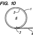
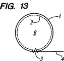
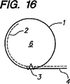
次に、図面を参照しながら説明する。図面中では同一の参照番号は同一又は類似の構成要素を示し、図1、2、3及び7はそれぞれ異なるSCRを表す。図1、2、3及び7の各々において、網目材1とフィルタ材2は巻き上げられ、位置3において、溶融接着等により互いに固定されており、網目構造のフラップ4は設置部材として巻き上げないままにしておく。図1〜3において、網目材1の重なり合う部分11a及び11b(図2では更に重なり合う部分11c)は出口部材を構成し、出口フィルタ21をそれらの間に挟んで有する。重なり合う部分12a及び12bは入口部材を構成し、図2及び3では(図1では異なる)入口フィルタ22をそれらの間に挟んで有する。図2において、入口フィルタは、出口フィルタの上部より下の高さまで伸び、よって上部にフィルタの無い部分を残している。図3では、出口フィルタ及び入口フィルタは、SCRの外周に連続するフィルタを形成する。図7では、重なり合いの範囲は、重なり合う区域を互いに固定するために必要な範囲だけに制限され、フィルタ21が上方に延びて設置部材の上表面を形成している。図1〜3及び7の各々において、SCC6は、入口部材及び出口部材によって封入される。
図4は、本発明の入口部材及び出口部材に用いることが可能なポリマー網目構造の一実施例の平面図である。網目構造は、図4に垂直方向の矢印で示される縦方向への押し出しにより形成する。ポリマーストランドの厚さをaで、平行四辺形の開口の鋭角をθで、ポリマーストランドに平行な大きい方の辺の寸法をxで、及びポリマーストランドに平行な小さい方の辺の寸法をyで表す。
Drawing Next, it demonstrates, referring drawings. In the drawings, the same reference numerals indicate the same or similar components, and FIGS. 1, 2, 3 and 7 represent different SCRs. In each of FIGS. 1, 2, 3 and 7, the
FIG. 4 is a plan view of an embodiment of a polymer network structure that can be used for the inlet member and the outlet member of the present invention. The network structure is formed by extrusion in the vertical direction indicated by the vertical arrow in FIG. The thickness of the polymer strand is a, the acute angle of the parallelogram opening is θ, the dimension of the larger side parallel to the polymer strand is x, and the dimension of the smaller side parallel to the polymer strand is y To express.
図5及び6は、図3に示すような、長さの異なるSCR6個で形成されたアセンブリの、それぞれ平面図と側面図である。SCRは、位置7A〜7Fにおいて各設置部材4A〜4Fを隣接するSCRに溶融接着することにより互いに接合されている。
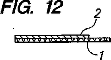
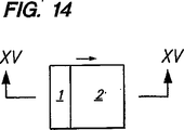
図8〜22において、ほぼ平坦な加工前部材は網目構造1、及び網目構造の全体(図8〜9)又は選択された部分(図11〜12、14〜15、17〜18及び20〜21)に亘って伸びるフィルタ材2を備える。加工前部材は、図8、11、14、17及び20の矢印で示される方向に巻き上げることができ、その結果加工前部材が重なり合う部分を位置3で互いに固定することにより、SCC6及び設置部材4を提供する。図20において、加工前部材は図22に示す生成されたSCRの設置部材の上表面を形成する、網目構造41の上層も含み、これは、沈殿物を含む液体の排水溝への流入を制御する用途に特に適している。
5 and 6 are a plan view and a side view, respectively, of an assembly formed of six SCRs having different lengths as shown in FIG. The SCRs are joined to each other by melting and bonding the
8-22, the substantially flat pre-processing member is the
図23において、土塊の坂232は、SCRのアセンブリ233により安定化されている。SCRの底部は坂の底部に掘られた溝231内に配置される。
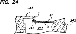
図24及び25では、図22に示される型のSCRを使用して、縁石244を有する歩道243と境界を接する道路242に設置された排水溝241中への、沈殿物を含む水の流入を制御している。排水溝は、縁石中の開口からの流入がある、歩道下部の後方部分を除き、格子245(その外周を図25の破線で示す)で覆われている。SCC6が縁石の開口を覆い、縁石の隣接部分と接触する。設置部材4が鉄格子245を覆い、道路の隣接部分に伸びる。
In FIG. 23, the
24 and 25, the flow of water including sediment into the
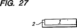
図26において、ほぼ平坦な加工前部材は、網目構造1、及び網目構造から伸長して網目構造の選択された部分に亘って伸びるフィルタ材2を備える。加工前部材は、矢印によって示される方向に巻き上げることができ、その結果得られた前駆体の重なり合う部分を位置3において互いに固定することにより、図27に示すようなSCC6及び設置部材4が提供される。
図28及び29は、図27に示すSCRと類似のSCRを表すが、このSCRには、C形の、開口を有する架橋部材9が固定されている。
In FIG. 26, the substantially flat pre-processing member includes a
28 and 29 show an SCR similar to the SCR shown in FIG. 27, to which a C-shaped bridging member 9 having an opening is fixed.
Claims (4)
1)液体の流動方向と垂直方向に細長い入口部材であって、
(i)装置の前側表面を供給し、(ii)多数の比較的大きな入口開口を有する、開口を有したシート材料の一枚シートであり、
各入口開口は0.01〜1.0平方インチ(6.5〜650mm2)の面積を有する、入口部材;
2)該垂直方向に細長い出口部材であって、
(i)装置の後側表面を供給し、(ii)多数の比較的大きな出口開口を有する、開口を有したシート材料の一枚シートであり、
各出口開口は0.01〜1.0平方インチ(6.5〜650mm2)の面積を有する、出口部材;及び
3)細長い出口フィルタであって、
(i)該出口部材の内部に固定され、該出口部材に支持され、
(ii)多数の相対的に小さなフィルタ開口を有し、さらに
(iii)100〜500ミクロンのメッシュサイズ及び0.5インチ(12.5mm)未満のほぼ均一の厚さを有する、
出口フィルタ;を含み、
該出口部材の一枚シートは該入口部材の一枚シートと一体とされた1枚の部片または互いに固定された別の部片であり、該出口部材と入口部材との間に細長い沈殿物収集チャンバ(SCC)を画定する1つの中空の柱状に形成され、該SCCは該出口フィルタのみを含むほかは中空である、装置。 A sediment control device for controlling sediment in a liquid, 1) an inlet member elongated in a direction perpendicular to a flow direction of the liquid ,
(I) a single sheet of sheet material having openings, supplying the front surface of the apparatus, and (ii) having a number of relatively large inlet openings;
Each inlet opening has an area of 0.01 to 1.0 square inches (6.5 to 650 mm < 2 >);
2) the vertically elongated outlet member,
(I) a single sheet of sheet material with openings, providing the rear surface of the apparatus, and (ii) having a number of relatively large exit openings,
Each outlet opening has an area of 0.01 to 1.0 square inches (6.5 to 650 mm 2 ), an outlet member; and 3) an elongated outlet filter,
(I) fixed inside the outlet member and supported by the outlet member;
(Ii) having a number of relatively small filter openings; and (iii) having a mesh size of 100-500 microns and a substantially uniform thickness of less than 0.5 inches (12.5 mm).
An outlet filter;
The single sheet of the outlet member is one piece integrated with the single sheet of the inlet member or another piece fixed to each other, and an elongated precipitate is disposed between the outlet member and the inlet member . An apparatus formed in one hollow column defining a collection chamber (SCC), the SCC being hollow except that it includes only the outlet filter.
1)液体の流動方向と垂直方向に細長い入口部材であって、
(i)装置の前側表面を供給し、(ii)多数の比較的大きな入口開口を有する、開口を有したシート材料の一枚シートであり、
各入口開口は0.01〜1.0平方インチ(6.5〜650mm2)の面積を有する、入口部材;
2)該垂直方向に細長い出口部材であって、
(i)装置の後側表面を供給し、(ii)多数の比較的大きな出口開口を有する、開口を有したシート材料の一枚シートであり、
各出口開口は0.01〜1.0平方インチ(6.5〜650mm2)の面積を有する、出口部材;及び
3)細長い出口フィルタであって、
(i)該出口部材の内部に固定され、該出口部材に支持され、
(ii)多数の相対的に小さなフィルタ開口を有し、さらに
(iii)100〜500ミクロンのメッシュサイズ及び0.5インチ(12.5mm)未満のほぼ均一の厚さを有する、
出口フィルタ;及び
4)細長い入口フィルタであって、
(i)該入口部材の内部に固定され、該入口部材に支持され、
(ii)多数の相対的に小さなフィルタ開口を有し、さらに
(iii)100〜500ミクロンのメッシュサイズ及び0.5インチ(12.5mm)未満のほぼ均一の厚さを有する、
入口フィルタ;
を含み、
該出口部材の一枚シートは該入口部材の一枚シートと一体とされた1枚の部片または互いに固定された別の部片であり、該出口部材と入口部材との間に細長い沈殿物収集チャンバ(SCC)を画定する1つの中空の柱状に形成され、該SCCは該出口フィルタと該細長い入口フィルタのみを含むほかは中空である、装置。 A sediment control device for controlling sediment in a liquid, 1) an inlet member elongated in a direction perpendicular to a flow direction of the liquid ,
(I) a single sheet of sheet material having openings, supplying the front surface of the apparatus, and (ii) having a number of relatively large inlet openings;
Each inlet opening has an area of 0.01 to 1.0 square inches (6.5 to 650 mm < 2 >);
2) the vertically elongated outlet member,
(I) a single sheet of sheet material with openings, providing the rear surface of the apparatus, and (ii) having a number of relatively large exit openings,
Each outlet opening has an area of 0.01 to 1.0 square inches (6.5 to 650 mm 2 ), an outlet member; and 3) an elongated outlet filter,
(I) fixed inside the outlet member and supported by the outlet member;
(Ii) having a number of relatively small filter openings; and (iii) having a mesh size of 100-500 microns and a substantially uniform thickness of less than 0.5 inches (12.5 mm).
An outlet filter; and 4) an elongated inlet filter,
(I) fixed inside the inlet member and supported by the inlet member;
(Ii) having a number of relatively small filter openings; and (iii) having a mesh size of 100-500 microns and a substantially uniform thickness of less than 0.5 inches (12.5 mm).
Inlet filter;
Including
The single sheet of the outlet member is one piece integrated with the single sheet of the inlet member or another piece fixed to each other, and an elongated precipitate is disposed between the outlet member and the inlet member . An apparatus formed in one hollow column defining a collection chamber (SCC), the SCC being hollow except for including only the outlet filter and the elongated inlet filter.
(iii)該設置部材を地中に埋設することにより前記装置を固定するために使用される、設置部材を有する、請求項1または2に記載の装置。An installation member, (i) fixed to the inlet member, (ii) extending outward from the device,
(Iii) The apparatus according to claim 1 or 2 , comprising an installation member used for fixing the apparatus by embedding the installation member in the ground.
(i)建築現場からの液体流出を防止する、または
(ii)排水溝への瓦礫及び沈殿物の流入を制御する、または
(iii)互いに固定され、水平面に対して軸が30ないし90°の角度を形成するように設置された多数の沈殿物制御装置を用いることによって、既存の土塊を安定させる、方法。A method of collecting sediment from a flowing stream of liquid containing sediment, comprising passing the flowing stream through an apparatus according to any one of claims 1 to 3, further comprising:
(I) prevent liquid outflow from the construction site, or (ii) control the inflow of rubble and sediment into the drain, or (iii) be fixed to each other and have an axis of 30-90 ° with respect to the horizontal plane A method of stabilizing an existing mass by using multiple sediment control devices installed to form an angle.
Applications Claiming Priority (5)
| Application Number | Priority Date | Filing Date | Title |
|---|---|---|---|
| US10/742,076 | 2003-12-19 | ||
| US10/742,076 US6848866B1 (en) | 2003-12-19 | 2003-12-19 | Sediment control |
| US10/843,010 | 2004-05-11 | ||
| US10/843,010 US7008144B2 (en) | 2003-12-19 | 2004-05-11 | Sediment control |
| PCT/US2004/042092 WO2005060645A2 (en) | 2003-12-19 | 2004-12-16 | Sediment control roll (scr) and method of collecting sediment |
Publications (3)
| Publication Number | Publication Date |
|---|---|
| JP2007516076A JP2007516076A (en) | 2007-06-21 |
| JP2007516076A5 JP2007516076A5 (en) | 2008-02-07 |
| JP4970047B2 true JP4970047B2 (en) | 2012-07-04 |
Family
ID=34704446
Family Applications (1)
| Application Number | Title | Priority Date | Filing Date |
|---|---|---|---|
| JP2006545370A Expired - Fee Related JP4970047B2 (en) | 2003-12-19 | 2004-12-16 | Sediment control |
Country Status (6)
| Country | Link |
|---|---|
| US (1) | US7172372B2 (en) |
| EP (1) | EP1694922A4 (en) |
| JP (1) | JP4970047B2 (en) |
| AU (1) | AU2004305059B2 (en) |
| CA (1) | CA2469683A1 (en) |
| WO (1) | WO2005060645A2 (en) |
Families Citing this family (11)
| Publication number | Priority date | Publication date | Assignee | Title |
|---|---|---|---|---|
| US7544016B2 (en) * | 2005-01-31 | 2009-06-09 | Ertec Environmental Systems Llc | Sediment control |
| US7736097B2 (en) * | 2006-04-14 | 2010-06-15 | M&D Environmental Barriers, Llp | Environmental barrier device |
| US8402630B2 (en) * | 2008-12-09 | 2013-03-26 | Ertec Environmental Systems | Barrier fence |
| KR101511374B1 (en) * | 2013-03-18 | 2015-04-10 | 한국과학기술연구원 | Membrane including macro-void support layer |
| US9816239B1 (en) | 2013-05-17 | 2017-11-14 | Ertec Environmental Systems Llc | Fence footing |
| CH710334A2 (en) * | 2014-11-04 | 2016-05-13 | Geobrugg Ag | Power system preferably for slope stabilization. |
| US10335724B1 (en) * | 2015-03-31 | 2019-07-02 | Ertec Environmental Systems Llc | Filter and barrier |
| US10864466B2 (en) | 2016-10-04 | 2020-12-15 | Ertec Environmental Systems Llc | Drain protection |
| US10893649B2 (en) * | 2018-07-30 | 2021-01-19 | George Patrick Solis | Bracing and blocking apparatus for a variety of uses |
| CN109948196B (en) * | 2019-02-28 | 2022-12-02 | 北京建筑大学 | Method for calculating starting characteristic of silt particles in drainage pipe |
| CN112495373A (en) * | 2020-12-10 | 2021-03-16 | 重庆大学 | Manganese-containing soil low-temperature denitration catalyst and preparation method thereof |
Family Cites Families (35)
| Publication number | Priority date | Publication date | Assignee | Title |
|---|---|---|---|---|
| US3112262A (en) * | 1960-07-12 | 1963-11-26 | New York Business Dev Corp | Filter unit and filter cartridge therefor |
| US3455112A (en) * | 1966-06-06 | 1969-07-15 | Kalle Ag | Installation for protecting surfendangered coastal sectors |
| JPS5643379Y2 (en) * | 1979-05-14 | 1981-10-12 | ||
| GB8504053D0 (en) | 1985-02-18 | 1985-03-20 | Alsop P | Erosion control matting |
| DE3507428A1 (en) * | 1985-03-02 | 1986-09-04 | MST-Dränbedarf GmbH & Co KG, 2832 Twistringen | Arrangement for stabilising slopes |
| US4954013A (en) * | 1987-06-12 | 1990-09-04 | Jacquelyn Lamberton | Means and method for stabilizing shorelines |
| JPS6443318A (en) * | 1987-08-10 | 1989-02-15 | Arai Tekkosho Kk | Multipurpose cylindrical element for filtration or separation |
| US4854773A (en) * | 1988-06-20 | 1989-08-08 | Nicoll James D | Beach carpet |
| US5108224A (en) * | 1989-09-01 | 1992-04-28 | Amoco Corporation | Silt control fabric |
| JPH0350384U (en) * | 1989-09-22 | 1991-05-16 | ||
| US5338131A (en) * | 1992-03-24 | 1994-08-16 | Lothar Bestmann | Arrangement for shoreline construction, maintenance, and protection, and methods for making and using the same |
| US5257878A (en) * | 1992-11-27 | 1993-11-02 | New York State Electric & Gas Corporation | Sediment mat |
| US5595458A (en) * | 1994-06-29 | 1997-01-21 | Grabhorn, Inc. | Biofilter bags for erosion control |
| US5575584A (en) * | 1994-08-01 | 1996-11-19 | Marine Environmental Solutions, L.L.C. | Underwater soil erosion prevention system |
| JP3145263B2 (en) * | 1995-01-30 | 2001-03-12 | 東洋紡績株式会社 | Drainage material used for temporary construction roads |
| US6010622A (en) * | 1996-12-18 | 2000-01-04 | Dandy Enterprises Limited | Environmental filter |
| US5632888A (en) * | 1995-05-11 | 1997-05-27 | Dandy Enterprises Limited | Environmental filter |
| CA2185087C (en) * | 1995-09-11 | 1999-02-02 | David W. Presby | Using multi-layer material in processing of septic effluent and waste water |
| JPH09313812A (en) * | 1996-05-28 | 1997-12-09 | Wako Sangyo Kk | Spiral filter element |
| US5733825A (en) * | 1996-11-27 | 1998-03-31 | Minnesota Mining And Manufacturing Company | Undrawn tough durably melt-bondable macrodenier thermoplastic multicomponent filaments |
| JPH1147516A (en) * | 1997-07-30 | 1999-02-23 | Toray Ind Inc | Method for treating water by filter cloth |
| US6277473B1 (en) * | 1998-01-23 | 2001-08-21 | Mcginn John | Structural member assembly |
| US6497532B1 (en) * | 1998-01-23 | 2002-12-24 | Mcginn John | Structural member for composite assembly device and method for erosion control and sediment retention |
| CA2263238C (en) * | 1999-03-01 | 2004-12-07 | Jack Mattson | Waterway pollution control apparatus |
| US6422787B1 (en) | 1999-09-24 | 2002-07-23 | Mike Mikell | Synthetic bale and method of using the same for erosion control |
| US6733209B2 (en) | 2000-01-07 | 2004-05-11 | Kristar Enterprises, Inc. | Chitosan enhanced erosion control rolls |
| US6641335B1 (en) | 2000-01-07 | 2003-11-04 | Kristar Enterprises, Inc. | Erosion control rolls |
| US6505996B1 (en) * | 2000-02-10 | 2003-01-14 | Tenax Corporation | Drainage system with unitary void-maintaining geosynthetic structure and method for constructing system |
| US6929425B1 (en) * | 2001-02-06 | 2005-08-16 | Greenfix America | Erosion control reinforcement mat |
| US6547493B2 (en) | 2001-03-13 | 2003-04-15 | Fiber King, Llp | Modular fiber log erosion and sediment control barrier |
| ITBO20010494A1 (en) * | 2001-07-30 | 2003-01-30 | Maccaferri Spa Off | LAND COATING STRUCTURE INCLUDING GEOCOMPOSITE LAYERS ENCLOSING A REINFORCEMENT ELEMENT, AND PROCEDURE FOR THE REALIZATION |
| US6893193B2 (en) * | 2002-01-30 | 2005-05-17 | B. Lanka Santha | Self-anchoring fiber block system |
| US6811708B2 (en) * | 2002-03-18 | 2004-11-02 | Ultratech International, Inc. | Curb guard filter |
| US6905289B1 (en) * | 2003-05-27 | 2005-06-14 | Peter S. Sanguinetti | Sediment control device and system |
| US6848866B1 (en) * | 2003-12-19 | 2005-02-01 | Mcginn John H. | Sediment control |
-
2004
- 2004-06-03 CA CA002469683A patent/CA2469683A1/en not_active Abandoned
- 2004-12-16 AU AU2004305059A patent/AU2004305059B2/en not_active Ceased
- 2004-12-16 WO PCT/US2004/042092 patent/WO2005060645A2/en active Application Filing
- 2004-12-16 JP JP2006545370A patent/JP4970047B2/en not_active Expired - Fee Related
- 2004-12-16 EP EP04817037A patent/EP1694922A4/en not_active Withdrawn
-
2005
- 2005-10-25 US US11/257,739 patent/US7172372B2/en not_active Expired - Lifetime
Also Published As
| Publication number | Publication date |
|---|---|
| US7172372B2 (en) | 2007-02-06 |
| CA2469683A1 (en) | 2005-06-19 |
| EP1694922A4 (en) | 2011-08-17 |
| AU2004305059B2 (en) | 2009-07-16 |
| US20060039761A1 (en) | 2006-02-23 |
| WO2005060645A2 (en) | 2005-07-07 |
| EP1694922A2 (en) | 2006-08-30 |
| WO2005060645A3 (en) | 2005-12-29 |
| JP2007516076A (en) | 2007-06-21 |
| AU2004305059A1 (en) | 2005-07-07 |
Similar Documents
| Publication | Publication Date | Title |
|---|---|---|
| US7008144B2 (en) | Sediment control | |
| US7172372B2 (en) | Sediment control | |
| US5605416A (en) | Water, sediment and erosion control apparatus and methods | |
| US7074326B2 (en) | Curb-and-grate inlet filter | |
| US6261445B1 (en) | Temporary silt guard for sewer inlet | |
| CA2586546C (en) | Culvert bundle for stream crossings and flow-through bridge abutments | |
| US20230043060A1 (en) | Fence system and method of use | |
| US10196283B2 (en) | Erosion and storm water control apparatus and method | |
| US20080131212A1 (en) | Sediment containment barrier | |
| JP2023505792A (en) | Horizontally expandable silt fence | |
| US10889950B2 (en) | Portable flood barrier system and method of use | |
| US7931423B2 (en) | Drainage element | |
| US7415923B2 (en) | Method of and system for sedimentation retaining barrier packing and handling | |
| US9051703B2 (en) | Drainage element and apparatus and method for making same | |
| RU93093U1 (en) | Geocell | |
| WO1995035417A1 (en) | Flooring for protection against erosion, and process for making such flooring | |
| CA2588196C (en) | Degradable erosion control barrier | |
| US20210285176A1 (en) | Flow-Responsive, Self-Adjusting Sediment Control Wattle | |
| US20160069034A1 (en) | Corrugated retention and filtration systems for sedimentation control | |
| Williams | Use of geotextile products in water control | |
| JPH04213611A (en) | Underdrainage pipe | |
| US20100135725A1 (en) | Drainage systems employing preassembled drainage elements |
Legal Events
| Date | Code | Title | Description |
|---|---|---|---|
| A521 | Request for written amendment filed |
Free format text: JAPANESE INTERMEDIATE CODE: A523 Effective date: 20071214 |
|
| A621 | Written request for application examination |
Free format text: JAPANESE INTERMEDIATE CODE: A621 Effective date: 20071214 |
|
| A131 | Notification of reasons for refusal |
Free format text: JAPANESE INTERMEDIATE CODE: A131 Effective date: 20110222 |
|
| A521 | Request for written amendment filed |
Free format text: JAPANESE INTERMEDIATE CODE: A523 Effective date: 20110523 |
|
| A131 | Notification of reasons for refusal |
Free format text: JAPANESE INTERMEDIATE CODE: A131 Effective date: 20110816 |
|
| A601 | Written request for extension of time |
Free format text: JAPANESE INTERMEDIATE CODE: A601 Effective date: 20111111 |
|
| A602 | Written permission of extension of time |
Free format text: JAPANESE INTERMEDIATE CODE: A602 Effective date: 20111118 |
|
| A601 | Written request for extension of time |
Free format text: JAPANESE INTERMEDIATE CODE: A601 Effective date: 20120111 |
|
| A602 | Written permission of extension of time |
Free format text: JAPANESE INTERMEDIATE CODE: A602 Effective date: 20120118 |
|
| A521 | Request for written amendment filed |
Free format text: JAPANESE INTERMEDIATE CODE: A523 Effective date: 20120125 |
|
| TRDD | Decision of grant or rejection written | ||
| A01 | Written decision to grant a patent or to grant a registration (utility model) |
Free format text: JAPANESE INTERMEDIATE CODE: A01 Effective date: 20120306 |
|
| A01 | Written decision to grant a patent or to grant a registration (utility model) |
Free format text: JAPANESE INTERMEDIATE CODE: A01 |
|
| A61 | First payment of annual fees (during grant procedure) |
Free format text: JAPANESE INTERMEDIATE CODE: A61 Effective date: 20120404 |
|
| FPAY | Renewal fee payment (event date is renewal date of database) |
Free format text: PAYMENT UNTIL: 20150413 Year of fee payment: 3 |
|
| R150 | Certificate of patent or registration of utility model |
Free format text: JAPANESE INTERMEDIATE CODE: R150 |
|
| LAPS | Cancellation because of no payment of annual fees |