US7736097B2 - Environmental barrier device - Google Patents
Environmental barrier device Download PDFInfo
- Publication number
- US7736097B2 US7736097B2 US11/556,401 US55640106A US7736097B2 US 7736097 B2 US7736097 B2 US 7736097B2 US 55640106 A US55640106 A US 55640106A US 7736097 B2 US7736097 B2 US 7736097B2
- Authority
- US
- United States
- Prior art keywords
- flexible member
- barrier device
- environmental barrier
- sheet
- ground
- Prior art date
- Legal status (The legal status is an assumption and is not a legal conclusion. Google has not performed a legal analysis and makes no representation as to the accuracy of the status listed.)
- Active, expires
Links
- 230000004888 barrier function Effects 0.000 title abstract description 52
- 230000007613 environmental effect Effects 0.000 title abstract description 51
- 239000000463 material Substances 0.000 claims abstract description 19
- 238000000034 method Methods 0.000 claims description 8
- 230000003628 erosive effect Effects 0.000 claims description 6
- 238000004162 soil erosion Methods 0.000 claims description 6
- 238000004873 anchoring Methods 0.000 claims description 3
- 239000012530 fluid Substances 0.000 claims 1
- 238000009434 installation Methods 0.000 claims 1
- 239000007787 solid Substances 0.000 claims 1
- XLYOFNOQVPJJNP-UHFFFAOYSA-N water Substances O XLYOFNOQVPJJNP-UHFFFAOYSA-N 0.000 abstract description 18
- 238000010276 construction Methods 0.000 description 20
- 239000002689 soil Substances 0.000 description 12
- 239000013049 sediment Substances 0.000 description 6
- 239000004744 fabric Substances 0.000 description 4
- 238000001914 filtration Methods 0.000 description 3
- 239000006260 foam Substances 0.000 description 2
- 230000006870 function Effects 0.000 description 2
- 229920000098 polyolefin Polymers 0.000 description 2
- 229920000426 Microplastic Polymers 0.000 description 1
- 239000004677 Nylon Substances 0.000 description 1
- 239000000853 adhesive Substances 0.000 description 1
- 230000001070 adhesive effect Effects 0.000 description 1
- 239000002131 composite material Substances 0.000 description 1
- 230000008878 coupling Effects 0.000 description 1
- 238000010168 coupling process Methods 0.000 description 1
- 238000005859 coupling reaction Methods 0.000 description 1
- 230000000694 effects Effects 0.000 description 1
- 238000003475 lamination Methods 0.000 description 1
- 229920001778 nylon Polymers 0.000 description 1
- 230000008439 repair process Effects 0.000 description 1
Images


Classifications
-
- B—PERFORMING OPERATIONS; TRANSPORTING
- B32—LAYERED PRODUCTS
- B32B—LAYERED PRODUCTS, i.e. PRODUCTS BUILT-UP OF STRATA OF FLAT OR NON-FLAT, e.g. CELLULAR OR HONEYCOMB, FORM
- B32B3/00—Layered products comprising a layer with external or internal discontinuities or unevennesses, or a layer of non-planar shape; Layered products comprising a layer having particular features of form
- B32B3/10—Layered products comprising a layer with external or internal discontinuities or unevennesses, or a layer of non-planar shape; Layered products comprising a layer having particular features of form characterised by a discontinuous layer, i.e. formed of separate pieces of material
-
- B—PERFORMING OPERATIONS; TRANSPORTING
- B32—LAYERED PRODUCTS
- B32B—LAYERED PRODUCTS, i.e. PRODUCTS BUILT-UP OF STRATA OF FLAT OR NON-FLAT, e.g. CELLULAR OR HONEYCOMB, FORM
- B32B3/00—Layered products comprising a layer with external or internal discontinuities or unevennesses, or a layer of non-planar shape; Layered products comprising a layer having particular features of form
- B32B3/26—Layered products comprising a layer with external or internal discontinuities or unevennesses, or a layer of non-planar shape; Layered products comprising a layer having particular features of form characterised by a particular shape of the outline of the cross-section of a continuous layer; characterised by a layer with cavities or internal voids ; characterised by an apertured layer
- B32B3/266—Layered products comprising a layer with external or internal discontinuities or unevennesses, or a layer of non-planar shape; Layered products comprising a layer having particular features of form characterised by a particular shape of the outline of the cross-section of a continuous layer; characterised by a layer with cavities or internal voids ; characterised by an apertured layer characterised by an apertured layer, the apertures going through the whole thickness of the layer, e.g. expanded metal, perforated layer, slit layer regular cells B32B3/12
-
- B—PERFORMING OPERATIONS; TRANSPORTING
- B32—LAYERED PRODUCTS
- B32B—LAYERED PRODUCTS, i.e. PRODUCTS BUILT-UP OF STRATA OF FLAT OR NON-FLAT, e.g. CELLULAR OR HONEYCOMB, FORM
- B32B5/00—Layered products characterised by the non- homogeneity or physical structure, i.e. comprising a fibrous, filamentary, particulate or foam layer; Layered products characterised by having a layer differing constitutionally or physically in different parts
- B32B5/18—Layered products characterised by the non- homogeneity or physical structure, i.e. comprising a fibrous, filamentary, particulate or foam layer; Layered products characterised by having a layer differing constitutionally or physically in different parts characterised by features of a layer of foamed material
-
- B—PERFORMING OPERATIONS; TRANSPORTING
- B32—LAYERED PRODUCTS
- B32B—LAYERED PRODUCTS, i.e. PRODUCTS BUILT-UP OF STRATA OF FLAT OR NON-FLAT, e.g. CELLULAR OR HONEYCOMB, FORM
- B32B5/00—Layered products characterised by the non- homogeneity or physical structure, i.e. comprising a fibrous, filamentary, particulate or foam layer; Layered products characterised by having a layer differing constitutionally or physically in different parts
- B32B5/22—Layered products characterised by the non- homogeneity or physical structure, i.e. comprising a fibrous, filamentary, particulate or foam layer; Layered products characterised by having a layer differing constitutionally or physically in different parts characterised by the presence of two or more layers which are next to each other and are fibrous, filamentary, formed of particles or foamed
-
- E—FIXED CONSTRUCTIONS
- E01—CONSTRUCTION OF ROADS, RAILWAYS, OR BRIDGES
- E01F—ADDITIONAL WORK, SUCH AS EQUIPPING ROADS OR THE CONSTRUCTION OF PLATFORMS, HELICOPTER LANDING STAGES, SIGNS, SNOW FENCES, OR THE LIKE
- E01F7/00—Devices affording protection against snow, sand drifts, side-wind effects, snowslides, avalanches or falling rocks; Anti-dazzle arrangements ; Sight-screens for roads, e.g. to mask accident site
- E01F7/02—Snow fences or similar devices, e.g. devices affording protection against sand drifts or side-wind effects
-
- B—PERFORMING OPERATIONS; TRANSPORTING
- B32—LAYERED PRODUCTS
- B32B—LAYERED PRODUCTS, i.e. PRODUCTS BUILT-UP OF STRATA OF FLAT OR NON-FLAT, e.g. CELLULAR OR HONEYCOMB, FORM
- B32B2250/00—Layers arrangement
- B32B2250/02—2 layers
Definitions
- the present teachings generally relate to environmental barrier devices. More particularly, the present teachings relate to such devices for reducing soil erosion at construction sites, for example, and a method of reducing soil erosion at construction sites.
- silt fence is a temporary barrier used to intercept sediment-laden runoff from small areas. Silt fences are effective in trapping sediment from all activities that involve soil disturbance. They can be used on adjacent properties, adjacent bodies of water, large sloping areas, near streams and waterways, near surface drainage ways and other areas to prevent water erosion and sediment movement.
- a conventional silt fence includes a fabric portion and a plurality of stakes.
- the fabric portion extends between the stakes.
- the stakes serve to anchor and support the fabric portion.
- the fabric functions to prevent unwanted erosion and sediment movement while permitting the passage of rainwater.
- silt fences While conventional silt fences have proven to be satisfactory for their intended use of preventing erosion and sediment movement, they are all associated with drawbacks and limitations. In this regard, construction vehicles may easily knock over a conventional silt fence and render it inoperative for its intended use. Accordingly, it remains a need in the pertinent art to provide an environmental barrier which prevents water erosion and sediment movement while overcoming the drawbacks and limitations associated with known structures, including but not limited to those discussed above.
- the present teachings provide an environmental barrier device that includes a first member and a second member.
- the first member may be constructed of a first sheet material and may have a memory retaining shape.
- the first member may be normally oriented in a generally upright position and resiliently deflectable from the generally upright position.
- the second member may be secured to the first member and may be constructed of a second sheet material.
- the second sheet material may be flexible and may define a filter media.
- the filter media may allow the passage of water through the barrier device and preclude the passage of dirt and silt through the barrier device.
- a lower portion of the first member may be positioned below ground level and an upper portion positioned above ground level.
- the environmental barrier device may be driven over or otherwise deflected from a generally upright orientation and the first member may automatically return the environmental barrier device to the generally upright orientation.
- the present teachings provide an environmental barrier device for permitting the passage of rain water and preventing the passage of soil.
- the environmental barrier device includes a flexible member having a length and a height. The length is substantially greater than the height.
- the flexible member has at least a portion that is a free-standing portion.
- the free-standing portion is deflectable from a generally vertical orientation when subjected to a load.
- the free-standing portion is further memory retaining so as to return to the generally vertical orientation when the load is removed.
- the environmental barrier device additionally includes means for permitting the passage of rain water through the flexible member and means for preventing the passage of soil through the flexible member.
- the present teachings provide a method of reducing soil erosion at a construction site while providing substantially unrestricted access to the construction site with construction vehicles.
- the method includes providing a flexible member having a length and a height, the length being substantially greater than the height.
- the method additionally involves anchoring the flexible member to the ground such that a free-standing portion of the flexible member upwardly extends from the ground.
- the method further includes deflecting the free-standing portion of the flexible member from the generally vertical orientation and resiliently returning the free-standing portion of the flexible member to the generally vertical orientation.
- FIG. 1 is an environmental view illustrating an environmental barrier device in accordance with the present teachings, the environmental barrier device shown operatively installed at a construction site, a construction vehicle shown crossing the environmental barrier device and thereby applying a load to the environmental device to deflect it from a normally upright orientation.
- FIG. 2 is a view of a portion of FIG. 1 illustrating the environmental barrier device after the construction vehicle has passed, the environmental barrier device resiliently returning to a generally vertical orientation after the load of the vehicle has been removed.
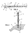
- FIG. 3 is a top view of the environmental barrier device in accordance with the present teachings and as shown installed in FIG. 1 , the environmental barrier device shown in cross section.
- FIG. 4 is a cross-sectional view taken along the line 4 - 4 of FIG. 3 .
- FIG. 5 is an enlarged front view of an environmental barrier device in accordance with the present teachings, the environmental barrier device shown operatively associated with a mounting bracket suitable for temporarily securing the environmental barrier device to a curb, for example.
- FIG. 6 is an enlarged rear view of an environmental barrier device in accordance with the present teachings, the environmental barrier device shown operatively associated with a mounting bracket suitable for temporarily securing the environmental barrier device to a curb, for example.
- an environmental barrier device constructed in accordance with the teachings of the present invention is illustrated and generally identified at reference character 10 .
- the environmental barrier device may be used at a construction site, for example.
- the environmental barrier device 10 may be used to reduce soil erosion.
- the environmental barrier device 10 may be positioned proximate a curb 12 (as shown in FIGS. 1 and 2 ) or other construction site boundary.
- the environmental barrier device 10 may be positioned in a trench 14 formed in undisturbed soil 16 .
- the trench 14 may be back-filled with disturbed soil 18 .
- the environmental barrier device 10 may be oriented in a generally vertical plane and define a barrier for reducing soil erosion.
- the environmental barrier device 10 may function to prevent the passage of silt from a construction site side to a street side, for example. Additionally, the environmental barrier device 10 may provide for the passage of water (e.g., rain water) from the construction site side to the street side.
- water e.g., rain water
- the environmental barrier device 10 may be anchored in the ground and otherwise be a self-standing structure. In this regard, it may not be necessary to support the environmental barrier device 10 with stakes or similar structure conventionally used to support a silt fence. In certain applications, the environmental barrier device 10 may be anchored approximately eight inches below ground level.
- the environmental barrier device 10 may be a resilient structure that is deflectable under load and which resiliently returns to a generally vertical orientation after the load is removed.
- the environmental view of FIG. 1 illustrates a portion of the environmental barrier device 10 deflected from the generally vertical orientation by the passage of a construction vehicle 20 .
- FIG. 2 the construction vehicle 20 has passed and the deflected portion of the environmental barrier device 10 automatically and resiliently returns to its generally vertical orientation.
- the environmental barrier device 10 includes a flexible member 22 having a length and a height. As will be addressed below, the length may be substantially greater than the height.
- the environmental barrier device 10 may additionally include means for permitting the passage of rain water through the flexible member 22 .
- the environmental barrier device 10 may further include means for preventing the passage of soil through the flexible member 22 .
- the flexible member 22 may include an upper portion 22 A and a lower portion 22 B.
- the lower portion 22 B is intended to be buried or otherwise anchored with respect to the ground.
- the upper portion 22 A is intended to upwardly extend from the ground.
- the lower portion 22 B need not have the same flexibility nor resiliency of the upper portion 22 A.
- the flexible member 22 of the environmental barrier device 10 may be a composite structure having a plurality of components or layers.
- the flexible member 22 may generally include a first member or first layer 24 and a second member or second layer 26 .
- the first member 24 may be constructed of a sheet material.
- the first member 24 may have a memory retaining shape and may provide the flexible member 22 with inherent resiliency to return to the generally vertical orientation or upright position.
- the first member 24 may be constructed from a polyolefin foam sheet.
- a polyolefin foam sheet is commercially available under the registered trademark Volara® from Sekisui America Corporation. Other materials having suitable resiliency, strength and/or durability characteristics may be alternatively utilized.
- the means for permitting the passage of rain water may include a plurality of holes or apertures 28 formed in the first member 24 .
- the holes 28 may be round, oval, any other suitable shape or combinations of shapes to permit the passage of rain water through the first member 24 . It will be appreciated that the location of the holes 28 , the hole pattern, the size of the holes 28 and the number of holes 28 may be varied from application to application within the scope of the present teachings.
- the means for permitting the passage of rain water may comprise a sheet material that allows for the passage of rain water but prevents the passage of soil.
- the means for preventing the passage of soil through the flexible member 22 may include a second member or second layer 26 .
- the second member 26 may be a filter member.
- the second member 26 may be positioned adjacent one of the sides of the first member 24 so as to cover the openings 28 .
- the second member 26 may be constructed of a second sheet material.
- the second sheet material 26 may be flexible and may define a filter media.
- the filter media 26 may allow the passage of water and preclude the passage of dirt and silt.
- the second member 26 may be a nylon mesh. Alternatively, any other material suitable for filtering soil from rain water may be employed.
- the means for filtering may simply be the holes 28 which are sized and provided in such number to provide the necessary filtering.
- the second member 26 may be secured to the first member 24 . In this regard, the second member 26 may be glued or laminated to the first member 24 . Alternatively, the second member 26 may be stitched or otherwise suitable secured to the first member 24 .
- the flexible member 22 may additionally include a third member or third layer 30 .
- the third member 30 may be constructed of a sheet material and may have a memory retaining shape. Again, while other materials may be employed, the third member 30 may be constructed of a polyolefin foam sheet. One suitable material is commercially available under the registered trademark Volora®.
- the third member 30 may include a plurality of holes or apertures.
- the second member 26 may be disposed between the first member 24 and the third member 30 .
- the third member 30 may be secured to the first member 24 and/or the second member 26 by adhesive, lamination, stretching or any other suitable manner.
- the flexible member 22 of the environmental barrier device 10 may be made in various lengths and heights. In one application, the flexible member 22 may be formed to have a length from approximately 50 feet to approximately 200 feet. The environmental barrier device 10 may be formed to have a height from approximately 20 inches to approximately 36 inches. In certain applications, it may be desirable to cut preformed sections to desired lengths.
- Separate lengths of the flexible member 22 may be joined with mechanical fasteners 32 .
- the flexible member 22 may be preformed with holes 34 (see FIG. 5 , for example) for receiving the mechanical fasteners 32 .
- the fasteners 32 may be used for splicing or repairs.
- One suitable mechanical fastener 32 is a two-piece fastener commercially available from Micro Plastics, Inc. of Flippin, Ark., as Part No. 27QB701000B.
- Other manners of coupling distinct lengths of the flexible member 22 including non-mechanical manners of fastening, may be employed within the scope of the present teachings.
- the lower portion 22 B of the flexible member 22 may be buried or otherwise anchored relative to the ground.
- approximately eight inches of the flexible member 22 may be set below grade for anchoring.
- Backfilling may be provided to support the flexible member 22 .
- the bracket 40 may be generally W-shaped and may engage the lower portion 22 B of the flexible member 22 .
- the bracket 40 may engage a fastener 42 (see FIG. 5 ).
- fasteners 42 may be mounted in a curb 12 and the bracket 40 may be used for temporarily securing the flexile member 22 relative to the curb 12 prior to the backfilling soil adjacent the curb 12 .
- an environmental barrier device 10 that facilitates the entry and egress of construction vehicles about a construction site.
- a device 10 is shown and described that may be provided in a roll to facilitate shipping and handling. Upon completion of construction at a construction site, the environmental barrier device 10 may be removed for subsequent re-use.
Landscapes
- Engineering & Computer Science (AREA)
- Architecture (AREA)
- Civil Engineering (AREA)
- Structural Engineering (AREA)
- Road Paving Structures (AREA)
Abstract
Description
Claims (2)
Priority Applications (5)
| Application Number | Priority Date | Filing Date | Title |
|---|---|---|---|
| US11/556,401 US7736097B2 (en) | 2006-04-14 | 2006-11-03 | Environmental barrier device |
| CA2611203A CA2611203C (en) | 2006-11-03 | 2007-05-22 | Environmental barrier device |
| PCT/US2007/012329 WO2008063235A1 (en) | 2006-11-03 | 2007-05-22 | Environmental barrier device |
| US12/006,857 US7901160B2 (en) | 2006-04-14 | 2008-01-07 | Environmental barrier device |
| US12/077,959 US20080181730A1 (en) | 2006-04-14 | 2008-03-20 | Environmental barrier device |
Applications Claiming Priority (2)
| Application Number | Priority Date | Filing Date | Title |
|---|---|---|---|
| US79238206P | 2006-04-14 | 2006-04-14 | |
| US11/556,401 US7736097B2 (en) | 2006-04-14 | 2006-11-03 | Environmental barrier device |
Related Child Applications (1)
| Application Number | Title | Priority Date | Filing Date |
|---|---|---|---|
| US12/006,857 Continuation US7901160B2 (en) | 2006-04-14 | 2008-01-07 | Environmental barrier device |
Publications (2)
| Publication Number | Publication Date |
|---|---|
| US20070042197A1 US20070042197A1 (en) | 2007-02-22 |
| US7736097B2 true US7736097B2 (en) | 2010-06-15 |
Family
ID=39367103
Family Applications (2)
| Application Number | Title | Priority Date | Filing Date |
|---|---|---|---|
| US11/556,401 Active 2027-02-10 US7736097B2 (en) | 2006-04-14 | 2006-11-03 | Environmental barrier device |
| US12/006,857 Active US7901160B2 (en) | 2006-04-14 | 2008-01-07 | Environmental barrier device |
Family Applications After (1)
| Application Number | Title | Priority Date | Filing Date |
|---|---|---|---|
| US12/006,857 Active US7901160B2 (en) | 2006-04-14 | 2008-01-07 | Environmental barrier device |
Country Status (3)
| Country | Link |
|---|---|
| US (2) | US7736097B2 (en) |
| CA (1) | CA2611203C (en) |
| WO (1) | WO2008063235A1 (en) |
Cited By (11)
| Publication number | Priority date | Publication date | Assignee | Title |
|---|---|---|---|---|
| US20090148243A1 (en) * | 2005-07-05 | 2009-06-11 | Mcginn John H | Controlling Sediment |
| US20090191009A1 (en) * | 2008-01-24 | 2009-07-30 | Kei-Chien Yu | Water and soil conservation method and a retaining wall for performing the same |
| US20120014747A1 (en) * | 2008-01-24 | 2012-01-19 | Kei-Chien Yu | Ecological board and its applications |
| WO2013040312A1 (en) * | 2011-09-16 | 2013-03-21 | Titanliner, Inc. | Portable containment systems for hazardous or other materials |
| US8465230B1 (en) | 2011-01-20 | 2013-06-18 | Paul D. O'Reilly | Silt fence support |
| US9126745B2 (en) | 2011-09-16 | 2015-09-08 | Titanliner, Inc. | Portable containment system for hazardous or other materials |
| US20190186098A1 (en) * | 2017-12-20 | 2019-06-20 | Chesapeake Environmental Management, Inc. | Silt Fence Patch and Methods Thereof |
| US10543935B2 (en) * | 2010-08-12 | 2020-01-28 | Ivry Shapira | Foreign object debris barrier for runways |
| US10843868B1 (en) | 2019-08-28 | 2020-11-24 | Titanliner, Inc. | Containment system for hazardous or other materials |
| US10893649B2 (en) * | 2018-07-30 | 2021-01-19 | George Patrick Solis | Bracing and blocking apparatus for a variety of uses |
| US11466413B2 (en) * | 2016-06-14 | 2022-10-11 | Mkb Company | Silt fence configured for capturing pollutants |
Families Citing this family (6)
| Publication number | Priority date | Publication date | Assignee | Title |
|---|---|---|---|---|
| US7762746B2 (en) * | 2007-07-19 | 2010-07-27 | Gary Berenyi | Silt fencing system |
| US7793476B2 (en) * | 2007-10-12 | 2010-09-14 | Sanders Steven H | Non-top supported fence installation bracket |
| AU2010291873A1 (en) * | 2009-09-04 | 2012-04-26 | Beta Vision Products Australia Pty Ltd | Silt barrier |
| US8740505B1 (en) * | 2010-03-11 | 2014-06-03 | J.F.R. Enterprises, Inc. | Erosion control methods and products for equipment pads |
| US9903105B2 (en) | 2015-05-22 | 2018-02-27 | Nathan L Tomberlin | Flow shield |
| GB201710301D0 (en) * | 2017-06-28 | 2017-08-09 | Annimex Int Ltd | Perforated fencing |
Citations (38)
| Publication number | Priority date | Publication date | Assignee | Title |
|---|---|---|---|---|
| US1668288A (en) * | 1926-12-03 | 1928-05-01 | Standard Traffic Marker Compan | Traffic sign |
| US4031676A (en) | 1976-03-29 | 1977-06-28 | Dally Don A | Water blocking device |
| US4162863A (en) | 1976-10-28 | 1979-07-31 | Rhone-Poulenc-Textile | Device for soil irrigation |
| US4279535A (en) * | 1979-10-01 | 1981-07-21 | Mercantile Development, Inc. | Material and system for minimizing erosion |
| US4605204A (en) * | 1984-08-13 | 1986-08-12 | Carsonite International Corporation | Collapsible recreational fence |
| US4756511A (en) | 1987-04-27 | 1988-07-12 | Certified Stake Co., Inc. | Silt fence |
| US5051028A (en) | 1988-03-04 | 1991-09-24 | Houck Randall J | Method and apparatus for installation of drainage field |
| US5128189A (en) | 1989-08-18 | 1992-07-07 | Bartlett David H | Disposable mat with compressible ridge |
| US5236281A (en) | 1992-07-15 | 1993-08-17 | New Pig Corporation | Dikes for damming or diverting liquids |
| US5464492A (en) | 1994-05-20 | 1995-11-07 | Renew Roof Technologies Inc. | Method for manufacturing a portable liquid spill containment system |
| US5536111A (en) | 1994-09-27 | 1996-07-16 | Doernemann; Jarett | Adjustable erosion control wall |
| US5605416A (en) * | 1995-03-27 | 1997-02-25 | Roach; Gary W. | Water, sediment and erosion control apparatus and methods |
| US5615499A (en) | 1995-04-17 | 1997-04-01 | Mcguire; Christopher J. | Method of and apparatus for trenching |
| US5636939A (en) | 1995-06-06 | 1997-06-10 | Brown; Gregory B. | Shoreline erosion-reversing system and method |
| US5743674A (en) | 1996-09-10 | 1998-04-28 | New Pig Corporation | Absorbent berm device |
| US5800091A (en) | 1996-01-26 | 1998-09-01 | Van Romer; Edward W. | Configurable containment system and wall strip |
| US5820297A (en) | 1996-08-27 | 1998-10-13 | New Pig Corporation | Permanent berm device |
| US5915878A (en) | 1997-01-07 | 1999-06-29 | Carpenter; Thomas Joseph | Silt fence machine |
| US5944443A (en) * | 1996-01-03 | 1999-08-31 | Beach Reclamation, Inc. | Adjustable porous groynes and method for shoreline reclamation |
| US5943798A (en) | 1995-04-17 | 1999-08-31 | Mcguire; Christopher J. | Method of and apparatus for trenching |
| US6053665A (en) | 1998-05-18 | 2000-04-25 | Richardson; Patrick C. | Silt fence fabric, apparatus and method |
| US6155546A (en) | 1998-03-10 | 2000-12-05 | Whitener; Shawn E. | Tool for use in installing silt fences |
| US6158923A (en) | 1998-09-25 | 2000-12-12 | Revoluntinary Machine And Installation Llc | Method and apparatus for installing silt fence |
| US6334736B1 (en) | 1997-07-30 | 2002-01-01 | Aqua Levee, Llc | Flood barrier |
| US6398459B1 (en) | 2001-06-19 | 2002-06-04 | Gregory M. Vreeland | Apparatus for installing a silt fence |
| US6455546B2 (en) | 1996-12-18 | 2002-09-24 | Clemson University | Method for promoting ovulation, parturition, and lactation in mammals |
| US6464428B1 (en) | 1999-09-24 | 2002-10-15 | Mike Mikell | Synthetic hay bale and method of using same |
| US6517294B2 (en) | 2001-06-19 | 2003-02-11 | Gregory M. Vreeland | Apparatus for installing a silt fence |
| US6540445B1 (en) | 2001-03-01 | 2003-04-01 | Eldon Boyd Evans, Jr. | Concrete silt fence |
| US6641335B1 (en) | 2000-01-07 | 2003-11-04 | Kristar Enterprises, Inc. | Erosion control rolls |
| US6796747B1 (en) | 2003-06-03 | 2004-09-28 | Gregory M. Vreeland | Apparatus for installing a silt fence and support posts |
| US20040217049A1 (en) * | 2002-10-24 | 2004-11-04 | Bayer Charlene W | Filters and methods of making and using the same |
| US6848866B1 (en) | 2003-12-19 | 2005-02-01 | Mcginn John H. | Sediment control |
| US20060171785A1 (en) | 2005-01-31 | 2006-08-03 | Mcginn John H | Sediment control |
| US7128497B2 (en) | 2003-12-02 | 2006-10-31 | Daluise Daniel A | Horizontally draining artificial turf system |
| US7131787B2 (en) | 2004-05-11 | 2006-11-07 | Ertec Environmental Systems Llc | Drain inlet cover |
| US7172372B2 (en) | 2003-12-19 | 2007-02-06 | Ertec Environmental Systems Llc | Sediment control |
| US20090148243A1 (en) | 2005-07-05 | 2009-06-11 | Mcginn John H | Controlling Sediment |
Family Cites Families (2)
| Publication number | Priority date | Publication date | Assignee | Title |
|---|---|---|---|---|
| JP2774416B2 (en) * | 1992-07-15 | 1998-07-09 | 株式会社さとうベネック | Lightweight embankment method |
| US6932540B2 (en) * | 2000-10-06 | 2005-08-23 | 3-R Foam, Inc. | Permeable water reservoir covers |
-
2006
- 2006-11-03 US US11/556,401 patent/US7736097B2/en active Active
-
2007
- 2007-05-22 WO PCT/US2007/012329 patent/WO2008063235A1/en not_active Ceased
- 2007-05-22 CA CA2611203A patent/CA2611203C/en active Active
-
2008
- 2008-01-07 US US12/006,857 patent/US7901160B2/en active Active
Patent Citations (39)
| Publication number | Priority date | Publication date | Assignee | Title |
|---|---|---|---|---|
| US1668288A (en) * | 1926-12-03 | 1928-05-01 | Standard Traffic Marker Compan | Traffic sign |
| US4031676A (en) | 1976-03-29 | 1977-06-28 | Dally Don A | Water blocking device |
| US4162863A (en) | 1976-10-28 | 1979-07-31 | Rhone-Poulenc-Textile | Device for soil irrigation |
| US4279535A (en) * | 1979-10-01 | 1981-07-21 | Mercantile Development, Inc. | Material and system for minimizing erosion |
| US4605204A (en) * | 1984-08-13 | 1986-08-12 | Carsonite International Corporation | Collapsible recreational fence |
| US4756511A (en) | 1987-04-27 | 1988-07-12 | Certified Stake Co., Inc. | Silt fence |
| US5051028A (en) | 1988-03-04 | 1991-09-24 | Houck Randall J | Method and apparatus for installation of drainage field |
| US5128189A (en) | 1989-08-18 | 1992-07-07 | Bartlett David H | Disposable mat with compressible ridge |
| US5236281A (en) | 1992-07-15 | 1993-08-17 | New Pig Corporation | Dikes for damming or diverting liquids |
| US5464492A (en) | 1994-05-20 | 1995-11-07 | Renew Roof Technologies Inc. | Method for manufacturing a portable liquid spill containment system |
| US5536111A (en) | 1994-09-27 | 1996-07-16 | Doernemann; Jarett | Adjustable erosion control wall |
| US5605416A (en) * | 1995-03-27 | 1997-02-25 | Roach; Gary W. | Water, sediment and erosion control apparatus and methods |
| US5615499A (en) | 1995-04-17 | 1997-04-01 | Mcguire; Christopher J. | Method of and apparatus for trenching |
| US5943798A (en) | 1995-04-17 | 1999-08-31 | Mcguire; Christopher J. | Method of and apparatus for trenching |
| US5636939A (en) | 1995-06-06 | 1997-06-10 | Brown; Gregory B. | Shoreline erosion-reversing system and method |
| US5944443A (en) * | 1996-01-03 | 1999-08-31 | Beach Reclamation, Inc. | Adjustable porous groynes and method for shoreline reclamation |
| US5800091A (en) | 1996-01-26 | 1998-09-01 | Van Romer; Edward W. | Configurable containment system and wall strip |
| US5820297A (en) | 1996-08-27 | 1998-10-13 | New Pig Corporation | Permanent berm device |
| US5743674A (en) | 1996-09-10 | 1998-04-28 | New Pig Corporation | Absorbent berm device |
| US6455546B2 (en) | 1996-12-18 | 2002-09-24 | Clemson University | Method for promoting ovulation, parturition, and lactation in mammals |
| US5915878A (en) | 1997-01-07 | 1999-06-29 | Carpenter; Thomas Joseph | Silt fence machine |
| US6334736B1 (en) | 1997-07-30 | 2002-01-01 | Aqua Levee, Llc | Flood barrier |
| US6155546A (en) | 1998-03-10 | 2000-12-05 | Whitener; Shawn E. | Tool for use in installing silt fences |
| US6053665A (en) | 1998-05-18 | 2000-04-25 | Richardson; Patrick C. | Silt fence fabric, apparatus and method |
| US6158923A (en) | 1998-09-25 | 2000-12-12 | Revoluntinary Machine And Installation Llc | Method and apparatus for installing silt fence |
| US6464428B1 (en) | 1999-09-24 | 2002-10-15 | Mike Mikell | Synthetic hay bale and method of using same |
| US6641335B1 (en) | 2000-01-07 | 2003-11-04 | Kristar Enterprises, Inc. | Erosion control rolls |
| US6540445B1 (en) | 2001-03-01 | 2003-04-01 | Eldon Boyd Evans, Jr. | Concrete silt fence |
| US6398459B1 (en) | 2001-06-19 | 2002-06-04 | Gregory M. Vreeland | Apparatus for installing a silt fence |
| US6517294B2 (en) | 2001-06-19 | 2003-02-11 | Gregory M. Vreeland | Apparatus for installing a silt fence |
| US20040217049A1 (en) * | 2002-10-24 | 2004-11-04 | Bayer Charlene W | Filters and methods of making and using the same |
| US6796747B1 (en) | 2003-06-03 | 2004-09-28 | Gregory M. Vreeland | Apparatus for installing a silt fence and support posts |
| US7128497B2 (en) | 2003-12-02 | 2006-10-31 | Daluise Daniel A | Horizontally draining artificial turf system |
| US7008144B2 (en) | 2003-12-19 | 2006-03-07 | Mcginn John H | Sediment control |
| US6848866B1 (en) | 2003-12-19 | 2005-02-01 | Mcginn John H. | Sediment control |
| US7172372B2 (en) | 2003-12-19 | 2007-02-06 | Ertec Environmental Systems Llc | Sediment control |
| US7131787B2 (en) | 2004-05-11 | 2006-11-07 | Ertec Environmental Systems Llc | Drain inlet cover |
| US20060171785A1 (en) | 2005-01-31 | 2006-08-03 | Mcginn John H | Sediment control |
| US20090148243A1 (en) | 2005-07-05 | 2009-06-11 | Mcginn John H | Controlling Sediment |
Non-Patent Citations (1)
| Title |
|---|
| International Search Report and Written Opinion of the International Searching Authority for International Application No. PCT/US07/12329, mailing date Feb. 26, 2008; 6 Pages. |
Cited By (22)
| Publication number | Priority date | Publication date | Assignee | Title |
|---|---|---|---|---|
| US20090148243A1 (en) * | 2005-07-05 | 2009-06-11 | Mcginn John H | Controlling Sediment |
| US7955030B2 (en) * | 2005-07-05 | 2011-06-07 | Ertec Environmental Systems Llc | Controlling sediment |
| US20090191009A1 (en) * | 2008-01-24 | 2009-07-30 | Kei-Chien Yu | Water and soil conservation method and a retaining wall for performing the same |
| US20120014747A1 (en) * | 2008-01-24 | 2012-01-19 | Kei-Chien Yu | Ecological board and its applications |
| US8579552B2 (en) * | 2008-01-24 | 2013-11-12 | Kei-Chien Yu | Ecological board and its applications |
| US10543935B2 (en) * | 2010-08-12 | 2020-01-28 | Ivry Shapira | Foreign object debris barrier for runways |
| US8465230B1 (en) | 2011-01-20 | 2013-06-18 | Paul D. O'Reilly | Silt fence support |
| US9828173B2 (en) | 2011-09-16 | 2017-11-28 | Titanliner, Inc. | Portable containment system for hazardous or other materials |
| US10549907B2 (en) | 2011-09-16 | 2020-02-04 | Titanliner, Inc. | Portable containment system for hazardous or other materials |
| US9221598B2 (en) | 2011-09-16 | 2015-12-29 | Titanliner, Inc. | Portable containment system for hazardous or other materials |
| US8998013B2 (en) | 2011-09-16 | 2015-04-07 | Titanliner, Inc. | Portable containment systems for hazardous or other materials |
| US10131494B2 (en) | 2011-09-16 | 2018-11-20 | Titanliner, Inc. | Portable containment system for hazardous or other materials |
| US9126745B2 (en) | 2011-09-16 | 2015-09-08 | Titanliner, Inc. | Portable containment system for hazardous or other materials |
| WO2013040312A1 (en) * | 2011-09-16 | 2013-03-21 | Titanliner, Inc. | Portable containment systems for hazardous or other materials |
| US11466413B2 (en) * | 2016-06-14 | 2022-10-11 | Mkb Company | Silt fence configured for capturing pollutants |
| US12000098B2 (en) | 2016-06-14 | 2024-06-04 | MKB Company, LLC | Silt fence configured for capturing pollutants and fabric forming the same |
| US12378736B2 (en) | 2016-06-14 | 2025-08-05 | Mazcon, A Kurtz Bros. Company, Llc | Silt fence configured for capturing pollutants and fabric forming the same |
| US20190186098A1 (en) * | 2017-12-20 | 2019-06-20 | Chesapeake Environmental Management, Inc. | Silt Fence Patch and Methods Thereof |
| US10753060B2 (en) * | 2017-12-20 | 2020-08-25 | Chesapeake Environmental Management, Inc. | Silt fence patch and methods thereof |
| US10893649B2 (en) * | 2018-07-30 | 2021-01-19 | George Patrick Solis | Bracing and blocking apparatus for a variety of uses |
| US10843868B1 (en) | 2019-08-28 | 2020-11-24 | Titanliner, Inc. | Containment system for hazardous or other materials |
| US11383924B2 (en) | 2019-08-28 | 2022-07-12 | Titanliner, Inc. | Containment system for hazardous or other materials |
Also Published As
| Publication number | Publication date |
|---|---|
| CA2611203C (en) | 2014-07-08 |
| CA2611203A1 (en) | 2008-05-03 |
| US7901160B2 (en) | 2011-03-08 |
| US20080213050A1 (en) | 2008-09-04 |
| US20070042197A1 (en) | 2007-02-22 |
| WO2008063235A1 (en) | 2008-05-29 |
Similar Documents
| Publication | Publication Date | Title |
|---|---|---|
| US7901160B2 (en) | Environmental barrier device | |
| GB2485278A (en) | Shallow bollard mounting | |
| US20090038214A1 (en) | Golf course bunker boundary protection system | |
| US20100178108A1 (en) | Shoreline erosion control system | |
| US12486634B2 (en) | Prefabricated vertical geotextile ditch check system | |
| JP5117793B2 (en) | Underground water tank | |
| US20150152617A1 (en) | Free Draining Seal Device and Installation Method for Mechanically Stabilized Earth Wall Structures | |
| US20030118405A1 (en) | Method of construction for draining the ground and the like | |
| KR100946096B1 (en) | A protective fence and mat with guiderail | |
| KR20200009620A (en) | fixing and draining plate assembly for constructing vegetation block | |
| JP2000120150A (en) | Rain water storing permeable structure | |
| JP2012167496A (en) | Wall body provided with liquefaction countermeasure and steel sheet pile with liquefaction prevention function | |
| TW201114981A (en) | Underground structure having an overlaid structure of resin-made layers | |
| US20080181730A1 (en) | Environmental barrier device | |
| JP2013083144A (en) | Liquefaction preventing structure | |
| JP2002115280A (en) | Water storage device | |
| KR101773329B1 (en) | Strike type drain structure body for ground and construction method thereof | |
| KR100413880B1 (en) | Revetment, natural stone holding unit assembly and natural stone holding unit | |
| US20170073955A1 (en) | Storm drain system | |
| JP3204379U (en) | Sheet installation structure without steel piles | |
| KR101050541B1 (en) | Drainage induction device for preventing soil outflow by running water | |
| US20030082015A1 (en) | Road protection system | |
| CN213773108U (en) | Central dividing strip leakage-proof device | |
| JP3130944U (en) | Cross-type side gutter unit and side drainage type grating lid that do not require iron frame and iron receiving frame | |
| KR200304525Y1 (en) | Netron mounting structure in order to prevent sliding of slope |
Legal Events
| Date | Code | Title | Description |
|---|---|---|---|
| AS | Assignment |
Owner name: M&D ENVIRONMENTAL BARRIERS, LLP, MICHIGAN Free format text: ASSIGNMENT OF ASSIGNORS INTEREST;ASSIGNORS:D'ANDRETA, MARK, MR.;MINI, STEPHEN, MR.;REEL/FRAME:018479/0331 Effective date: 20061102 Owner name: M&D ENVIRONMENTAL BARRIERS, LLP,MICHIGAN Free format text: ASSIGNMENT OF ASSIGNORS INTEREST;ASSIGNORS:D'ANDRETA, MARK, MR.;MINI, STEPHEN, MR.;REEL/FRAME:018479/0331 Effective date: 20061102 |
|
| STCF | Information on status: patent grant |
Free format text: PATENTED CASE |
|
| FPAY | Fee payment |
Year of fee payment: 4 |
|
| AS | Assignment |
Owner name: SILTSHIELD LLC, MICHIGAN Free format text: ASSIGNMENT OF ASSIGNORS INTEREST;ASSIGNOR:M&D ENVIRONMENTAL BARRIERS, LLP;REEL/FRAME:032540/0677 Effective date: 20140326 |
|
| MAFP | Maintenance fee payment |
Free format text: PAYMENT OF MAINTENANCE FEE, 8TH YR, SMALL ENTITY (ORIGINAL EVENT CODE: M2552) Year of fee payment: 8 |
|
| MAFP | Maintenance fee payment |
Free format text: PAYMENT OF MAINTENANCE FEE, 12TH YR, SMALL ENTITY (ORIGINAL EVENT CODE: M2553); ENTITY STATUS OF PATENT OWNER: SMALL ENTITY Year of fee payment: 12 |