JP4969940B2 - Spout wearing method - Google Patents
Spout wearing method Download PDFInfo
- Publication number
- JP4969940B2 JP4969940B2 JP2006209052A JP2006209052A JP4969940B2 JP 4969940 B2 JP4969940 B2 JP 4969940B2 JP 2006209052 A JP2006209052 A JP 2006209052A JP 2006209052 A JP2006209052 A JP 2006209052A JP 4969940 B2 JP4969940 B2 JP 4969940B2
- Authority
- JP
- Japan
- Prior art keywords
- spout
- pouch
- opening
- mounting
- edge
- Prior art date
- Legal status (The legal status is an assumption and is not a legal conclusion. Google has not performed a legal analysis and makes no representation as to the accuracy of the status listed.)
- Active
Links
- 238000000034 method Methods 0.000 title claims description 39
- 238000007789 sealing Methods 0.000 claims description 23
- 238000003780 insertion Methods 0.000 claims description 22
- 230000037431 insertion Effects 0.000 claims description 22
- 230000007246 mechanism Effects 0.000 description 10
- 238000001816 cooling Methods 0.000 description 5
- 230000014759 maintenance of location Effects 0.000 description 4
- 239000013256 coordination polymer Substances 0.000 description 2
- 230000000694 effects Effects 0.000 description 2
- 238000009499 grossing Methods 0.000 description 2
- 239000007788 liquid Substances 0.000 description 1
- 230000004048 modification Effects 0.000 description 1
- 238000012986 modification Methods 0.000 description 1
- 229920003002 synthetic resin Polymers 0.000 description 1
- 239000000057 synthetic resin Substances 0.000 description 1
- 230000007723 transport mechanism Effects 0.000 description 1
Images


Classifications
-
- B—PERFORMING OPERATIONS; TRANSPORTING
- B65—CONVEYING; PACKING; STORING; HANDLING THIN OR FILAMENTARY MATERIAL
- B65D—CONTAINERS FOR STORAGE OR TRANSPORT OF ARTICLES OR MATERIALS, e.g. BAGS, BARRELS, BOTTLES, BOXES, CANS, CARTONS, CRATES, DRUMS, JARS, TANKS, HOPPERS, FORWARDING CONTAINERS; ACCESSORIES, CLOSURES, OR FITTINGS THEREFOR; PACKAGING ELEMENTS; PACKAGES
- B65D75/00—Packages comprising articles or materials partially or wholly enclosed in strips, sheets, blanks, tubes, or webs of flexible sheet material, e.g. in folded wrappers
- B65D75/52—Details
- B65D75/58—Opening or contents-removing devices added or incorporated during package manufacture
- B65D75/5861—Spouts
- B65D75/5872—Non-integral spouts
- B65D75/5883—Non-integral spouts connected to the package at the sealed junction of two package walls
-
- B—PERFORMING OPERATIONS; TRANSPORTING
- B31—MAKING ARTICLES OF PAPER, CARDBOARD OR MATERIAL WORKED IN A MANNER ANALOGOUS TO PAPER; WORKING PAPER, CARDBOARD OR MATERIAL WORKED IN A MANNER ANALOGOUS TO PAPER
- B31B—MAKING CONTAINERS OF PAPER, CARDBOARD OR MATERIAL WORKED IN A MANNER ANALOGOUS TO PAPER
- B31B70/00—Making flexible containers, e.g. envelopes or bags
- B31B70/74—Auxiliary operations
- B31B70/81—Forming or attaching accessories, e.g. opening devices, closures or tear strings
- B31B70/84—Forming or attaching means for filling or dispensing contents, e.g. valves or spouts
- B31B70/844—Applying rigid valves, spouts, or filling tubes
-
- Y—GENERAL TAGGING OF NEW TECHNOLOGICAL DEVELOPMENTS; GENERAL TAGGING OF CROSS-SECTIONAL TECHNOLOGIES SPANNING OVER SEVERAL SECTIONS OF THE IPC; TECHNICAL SUBJECTS COVERED BY FORMER USPC CROSS-REFERENCE ART COLLECTIONS [XRACs] AND DIGESTS
- Y10—TECHNICAL SUBJECTS COVERED BY FORMER USPC
- Y10T—TECHNICAL SUBJECTS COVERED BY FORMER US CLASSIFICATION
- Y10T29/00—Metal working
- Y10T29/49—Method of mechanical manufacture
- Y10T29/49826—Assembling or joining
- Y10T29/49833—Punching, piercing or reaming part by surface of second part
-
- Y—GENERAL TAGGING OF NEW TECHNOLOGICAL DEVELOPMENTS; GENERAL TAGGING OF CROSS-SECTIONAL TECHNOLOGIES SPANNING OVER SEVERAL SECTIONS OF THE IPC; TECHNICAL SUBJECTS COVERED BY FORMER USPC CROSS-REFERENCE ART COLLECTIONS [XRACs] AND DIGESTS
- Y10—TECHNICAL SUBJECTS COVERED BY FORMER USPC
- Y10T—TECHNICAL SUBJECTS COVERED BY FORMER US CLASSIFICATION
- Y10T29/00—Metal working
- Y10T29/53—Means to assemble or disassemble
Description
この発明は、スパウトをパウチに装着するスパウト装着方法に関する。 The present invention relates to a spout attachment method for attaching a spout to a pouch.
例えば、合成樹脂フィルム等のフレキシブルシートによって形成されたサイドガセット部を有するパウチの上縁部分に、飲口や注口となるスパウトが装着されたパウチ容器は、上縁部分がヒートシールされていないパウチを別工程によって予め製造しておき、このパウチの開放された上縁部分にスパウトの装着部が挟み込まれるように、スパウトをパウチに挿入し、その状態で、パウチの上縁部分をヒートシールすることによって、スパウトをパウチに装着することになる。 For example, a pouch container in which a spout serving as a mouthpiece or a spout is attached to the upper edge portion of a pouch having a side gusset portion formed of a flexible sheet such as a synthetic resin film, the upper edge portion is not heat sealed. The pouch is pre-manufactured in a separate process, and the spout is inserted into the pouch so that the spout mounting portion is sandwiched between the open upper edge portion of the pouch. In this state, the upper edge portion of the pouch is heat sealed. By doing so, the spout is attached to the pouch.
ところで、こういったパウチへのスパウトの装着作業は、パウチを各作業位置に順次停止させながら間欠的に搬送し、各作業位置においてそれぞれの作業を実行することによって段階的に行うのが一般的であるが、スパウトのパウチへの挿入からヒートシールまでの一連の作業を同一作業位置において行うと、パウチへのスパウトの挿入作業を行った後に、ある程度の時間を要する、パウチに対するスパウトのヒートシール作業を行わなければならないので、パウチへのスパウトの装着作業を高速化することができないといった問題がある。 By the way, it is common to perform the work of attaching the spout to such a pouch in stages by intermittently transporting the pouch while sequentially stopping at each work position and executing each work at each work position. However, if a series of operations from insertion of the spout into the pouch to heat sealing is performed at the same work position, it takes a certain amount of time after the spout is inserted into the pouch, and the heat sealing of the spout against the pouch is required. Since the work must be performed, there is a problem that the speed of attaching the spout to the pouch cannot be increased.
従って、パウチPの開放された上縁部分にスパウトを挿入した後、直ちに、その上縁部分を全体的にヒートシールしてスパウトをパウチに装着するのではなく、図12に示すように、パウチPの上縁部分UEに挿入されたスパウトSにおける装着部IPの中央部をパウチPの上縁部分にポイントシールすることによって一旦仮止めし、その状態で次の作業位置まで搬送し、次の作業位置において、上縁部分UEを全体的にヒートシールすることにより、スパウトSをパウチPに装着することが一般的に行われている。なお、図12における網掛け表示部分がパウチPのヒートシール領域であり、符号PSがポイントシール部分を示している。 Therefore, immediately after the spout is inserted into the open upper edge portion of the pouch P, the upper edge portion is not entirely heat-sealed and the spout is attached to the pouch, as shown in FIG. The center part of the mounting part IP in the spout S inserted in the upper edge part P of the P is temporarily sealed by point sealing to the upper edge part of the pouch P, and then transported to the next working position in that state. Generally, the spout S is attached to the pouch P by heat-sealing the upper edge portion UE as a whole at the working position. Note that the shaded display portion in FIG. 12 is the heat seal region of the pouch P, and the symbol PS indicates the point seal portion.
しかしながら、上述したように、パウチPをスパウトSにポイントシールする場合であっても、パウチPをスパウトSに部分的にヒートシールするには、パウチP及びスパウトS双方の接触面を部分的に溶融状態にしなければならず、硬くて肉厚の大きいスパウトSの表面を溶融するためにはある程度の時間を要するので、パウチPへのスパウトSの装着作業の高速化には限界がある。 However, as described above, even when the pouch P is point-sealed to the spout S, in order to partially heat-seal the pouch P to the spout S, the contact surfaces of both the pouch P and the spout S are partially Since a certain amount of time is required to melt the surface of the spout S that is hard and thick, it has a limit in speeding up the work of attaching the spout S to the pouch P.
また、こういったパウチ容器では、パウチPの幅方向の中央部にスパウトSを装着するのが一般的であるので、スパウトSにおける装着部IPの中央部をパウチPの上縁部分UEにポイントシールする場合は、図13に示すように、シールヘッドSHがパウチPの幅方向の中央部に配置されることになる。従って、パウチPの開放された上縁部分UEを開くための吸引ヘッドVHを、シールヘッドSHの両側にそれぞれ配置し、パウチPの幅方向の外側の2箇所を吸引ヘッドVHによって吸引してパウチPの開放された上縁部分UEを開かなければならないが、パウチPの幅方向の中央部を吸引してパウチPの開放された上縁部分UEを開く場合に比べて、パウチPの上縁部分UEの開き量が小さくなり、スパウトSをパウチPの上縁部分UEに挿入しづらくなるといった問題がある。特に、パウチPの幅が小さい場合は、この問題が顕著に現れることになり、場合によっては、パウチPから吸引ヘッドVHが外れてしまうこともある。 In such a pouch container, since the spout S is generally attached to the central portion in the width direction of the pouch P, the central portion of the attachment portion IP in the spout S is pointed to the upper edge portion UE of the pouch P. In the case of sealing, the seal head SH is disposed at the center in the width direction of the pouch P as shown in FIG. Accordingly, the suction heads VH for opening the upper edge portion UE where the pouch P is opened are respectively arranged on both sides of the seal head SH, and the two places outside the width direction of the pouch P are sucked by the suction head VH to pouch. The upper edge portion UE where the P is opened must be opened, but the upper edge of the pouch P is larger than when the upper edge portion UE where the pouch P is opened is opened by sucking the central portion in the width direction of the pouch P. There is a problem that the opening amount of the portion UE becomes small and it becomes difficult to insert the spout S into the upper edge portion UE of the pouch P. In particular, when the width of the pouch P is small, this problem appears remarkably. In some cases, the suction head VH may be detached from the pouch P.
そこで、この発明の課題は、パウチへのスパウトの装着作業の円滑化及び高速化を図ることができるスパウト装着方法を提供することにある。 Accordingly, an object of the present invention is to provide a spout mounting method capable of facilitating and speeding up the operation of mounting a spout on a pouch.
上記の課題を解決するため、請求項1にかかる発明は、スパウトをパウチに装着するスパウト装着方法であって、スパウトの装着部がパウチにおける未シールの開口縁に挟み込まれるように、スパウトをパウチに挿入する挿入工程と、パウチに挿入されたスパウトをパウチに仮止めする仮止め工程と、パウチに仮止めされたスパウトの装着部をパウチの開口縁にヒートシールするシール工程とを備え、前記仮止め工程では、パウチの開口縁によってスパウトを把持するように、スパウトの装着部の両側縁近傍においてパウチの開口縁同士をポイントシールするようにしたことを特徴とするスパウト装着方法を提供するものである。
In order to solve the above-mentioned problem, the invention according to
また、請求項2にかかる発明は、請求項1に係る発明のスパウト装着方法において、パウチの開口縁にヒートシールされるスパウトの装着部におけるパウチの幅方向の少なくとも一方の側縁が扁平な薄肉状に形成されている場合、前記仮止め工程において、パウチの開口縁同士をポイントシールする際、パウチの開口縁とスパウトの装着部における扁平な薄肉状の側縁とを併せてポイントシールするようにしたのである。
The invention according to
また、請求項3にかかる発明は、パウチの開口縁にヒートシールされるスパウトの装着部におけるパウチの幅方向の少なくとも一方の側縁が扁平な薄肉状に形成されており、その扁平な薄肉状の側縁の一部が内側に切り欠かれているスパウトをパウチに装着するスパウト装着方法であって、スパウトの装着部がパウチにおける未シールの開口縁に挟み込まれるように、スパウトをパウチに挿入する挿入工程と、パウチに挿入されたスパウトをパウチに仮止めする仮止め工程と、パウチに仮止めされたスパウトの装着部をパウチの開口縁にヒートシールするシール工程とを備え、前記仮止め工程では、スパウトの装着部における扁平な薄肉状の側縁に形成された切欠部にシール領域がかかるように、スパウトの装着部の両側縁近傍においてパウチの開口縁同士をポイントシールするようにしたことを特徴とするスパウト装着方法を提供するものである。
In the invention according to
以上のように、請求項1にかかる発明のスパウト装着方法では、仮止め工程において、パウチの開口縁によってスパウトを把持するように、スパウトの装着部の両側縁近傍においてパウチの開口縁同士をポイントシールするようにしたので、パウチをスパウトに直接ポイントシールしなくても、スパウトを把持しているパウチの開口縁の把持力によって、スパウトをパウチの所定位置に保持することができると共に、パウチに挿入されたスパウトにおける装着部の中央部をパウチの開口縁にポイントシールすることによって仮止めしている従来のスパウト装着方法に比べて、スパウトの仮止めに要する時間を削減することができる。従って、パウチへのスパウトの装着作業の円滑化及び高速化を図ることができる。
As described above, in the spout mounting method of the invention according to
また、このスパウト装着方法のように、スパウトの装着部の外側をポイントシールする場合は、スパウトの装着部の中央部を吸引保持してパウチの開口縁を開くことができるので、スパウトの装着部の中央部をポイントシールするため、パウチの幅方向の外側の2箇所を吸引保持してパウチの開口縁を開かなければならない従来のスパウト装着方法に比べて、パウチの開口縁の開き量が大きくなり、スパウトをパウチに挿入し易くなるという効果が得られる。特に、パウチの幅が小さく、十分に大きく開くことができない小型のパウチの場合に有効である。 In addition, when the outside of the spout attachment part is point-sealed as in this spout attachment method, the opening edge of the pouch can be opened by sucking and holding the center part of the spout attachment part. Compared with the conventional spout mounting method in which the opening edge of the pouch has to be opened by sucking and holding two places outside in the width direction of the pouch in order to point seal the center part of the pouch, the opening amount of the opening edge of the pouch is large Thus, the effect of facilitating insertion of the spout into the pouch can be obtained. This is particularly effective in the case of a small pouch that has a small width and cannot be opened sufficiently large.
また、パウチの開口縁にヒートシールされるスパウトの装着部におけるパウチの幅方向の少なくとも一方の側縁が扁平な薄肉状に形成されている場合は、請求項2にかかる発明のスパウト装着方法のように、仮止め工程において、パウチの開口縁同士をポイントシールする際、パウチの開口縁とスパウトの装着部における扁平な薄肉状の側縁とを併せてポイントシールするようにしておくと、請求項1にかかる発明のスパウト装着方法に比べて、スパウトの仮止めに要する時間を極端に増大させることなく、仮止め状態におけるパウチに対するスパウトの保持性を向上させることができる。
Further, in the case where at least one side edge in the width direction of the pouch in the mounting portion of the spout that is heat-sealed to the opening edge of the pouch is formed in a flat thin shape, the spout mounting method of the invention according to claim 2 Thus, in the temporary fixing step, when point-sealing the opening edges of the pouch, if the point edge of the opening edge of the pouch and the flat thin-walled side edge in the attachment part of the spout is point-sealed, Compared with the spout mounting method of the invention according to
また、パウチの開口縁にヒートシールされるスパウトの装着部におけるパウチの幅方向の少なくとも一方の側縁が扁平な薄肉状に形成されており、その扁平な薄肉状の側縁の一部が内側に切り欠かれているスパウトを用いる場合、仮止め工程において、スパウトの装着部における扁平な薄肉状の側縁に形成された切欠部にシール領域がかかるように、スパウトの装着部の両側縁近傍においてパウチの開口縁同士をポイントシールする請求項3にかかる発明のスパウト装着方法を採用することにより、請求項1にかかる発明のスパウト装着方法に比べて、スパウトの仮止めに要する時間を全く増大させることなく、仮止め状態におけるパウチに対するスパウトの保持性を向上させることができる。
In addition, at least one side edge in the width direction of the pouch in the attachment portion of the spout that is heat sealed to the opening edge of the pouch is formed in a flat thin shape, and a part of the flat thin side edge is on the inner side. When using a spout that is notched in the vicinity of both side edges of the spout mounting part so that the sealing area covers the notch part formed on the flat thin side edge of the spout mounting part in the temporary fixing process By adopting the spout mounting method of the invention according to
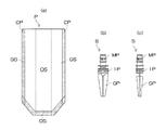
以下、実施の形態について図面を参照して説明する。図1は、本発明のスパウト装着方法によって、図2(a)に示すパウチPに、同図(b)、(c)に示すスパウトSが装着されたスパウト付きパウチ容器を示している。 Hereinafter, embodiments will be described with reference to the drawings. FIG. 1 shows a pouch container with a spout in which the spout P shown in FIG. 2 (a) is attached to the pouch P shown in FIG. 2 (c) by the spout attaching method of the present invention.
スパウトSが装着された状態のパウチPは、図1に示すように、表裏一対の外装シートOS及び両外装シートOSの両側部から内側に折り込まれて左右のガセット部を形成する左右一対のガセットシートGSから構成されており、折り込まれたガセットシートGSの内面の周縁が外装シートOSの内面にヒートシールされると共に、外装シートOSの内面の上縁部及び下縁部が相互にヒートシールされることで、袋状に形成されている。また、ガセットシートGSの両側縁の上端部には、二つ折りした状態で相互に一致する切欠部CPがそれぞれ形成されており、この切欠部CPを介して、外装シートOSの両側縁における上端部同士が部分的にヒートシールされている。また、スパウトSが装着される前のパウチPは、別工程で予め製造されており、図2(a)に示すように、外装シートOSの上縁部はヒートシールされていない。なお、図1及び図2(a)における網掛け表示部分が、パウチPのヒートシール部分を示している。 As shown in FIG. 1, the pouch P with the spout S attached is a pair of front and back exterior sheets OS and a pair of left and right gussets that are folded inward from both sides of the exterior sheet OS to form left and right gusset portions. The outer periphery of the folded gusset sheet GS is heat sealed to the inner surface of the exterior sheet OS, and the upper and lower edges of the inner surface of the exterior sheet OS are heat sealed to each other. Thus, it is formed in a bag shape. In addition, the upper end portions of both side edges of the gusset sheet GS are formed with cutout portions CP that are mutually matched in a folded state, and the upper end portions on both side edges of the exterior sheet OS are formed through the cutout portions CP. They are partially heat sealed. Further, the pouch P before the spout S is mounted is manufactured in advance in a separate process, and the upper edge portion of the exterior sheet OS is not heat-sealed as shown in FIG. The shaded display portions in FIGS. 1 and 2A indicate the heat seal portion of the pouch P.
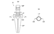
スパウトSは、図1及び図2(b)、(c)に示すように、パウチPに充填された液体商品を注ぎ出すための口部MPと、この口部MPに連設された、断面形状が舟形状の装着部IPと、この装着部IPに連設された導出部GPとから構成されており、装着部IPがパウチPの上縁に挟み込まれた状態でヒートシールされている。 As shown in FIG. 1 and FIGS. 2 (b) and 2 (c), the spout S has a mouth portion MP for pouring out liquid merchandise filled in the pouch P, and a cross section provided continuously to the mouth portion MP. The shape includes a boat-shaped mounting portion IP and a lead-out portion GP connected to the mounting portion IP. The mounting portion IP is heat-sealed in a state where it is sandwiched between the upper edges of the pouch P.
図3は、このスパウト装着方法を実施するためのスパウト装着装置1を示している。このスパウト装着装置1は、図示しないパウチ供給部によって立てた状態でパウチ供給位置αに供給されたパウチPを、パウチ予備開口位置β、スパウト挿入位置γ、第1シール位置δ、第2シール位置ε、冷却位置ζ及び排出位置ηに順次搬送するパウチ搬送部2、パウチ予備開口位置βにおいてパウチPの開口縁を一対の予備吸引ヘッド31、31によって吸引保持した状態で相互に離反させることによって予備的に開口するパウチ予備開口部3と、図示しないスパウト供給部によって供給されるスパウトSを、スパウト挿入位置γにおいて、パウチPに挿入してパウチPに仮止めするスパウト挿入・仮止め部4と、パウチPに仮止めされたスパウトSをパウチPにヒートシールすることによって装着するスパウト装着部5を備えている。
FIG. 3 shows a
前記パウチ搬送部2は、パウチ供給部によって立てた状態でパウチ供給位置αに供給されるパウチPを挟み込んでパウチ予備開口位置β側に送出する、パウチ供給位置α側が開閉可能な開閉ベルト搬送機構21と、この開閉ベルト搬送機構21によって搬送されてくるパウチPを挟み込んで、パウチ予備開口位置β、スパウト挿入位置γ、第1シール位置δ、第2シール位置ε、冷却位置ζ及び排出位置ηに順次搬送するベルト搬送機構22とを備えており、開閉ベルト搬送機構21及びベルト搬送機構22は、パウチPにおける装着されるスパウトSの下側を挟み込むようになっている。
The
前記スパウト挿入・仮止め部4は、スパウト供給部によって供給されるスパウトSを、その口部を把持した状態で吊り下げるチャックと、このチャックを昇降させるチャック昇降機構と、このチャック昇降機構をスパウト供給位置(図示せず)とスパウト挿入位置γとの間で移動させるチャック移動機構と、スパウト挿入位置γにおいてパウチPの開口縁を開口する一対の吸引ヘッド41、41と、パウチPに挿入されたスパウトSをパウチPに仮止めする一対のシールヘッド44a、44bとを備えており、スパウト挿入位置γに位置しているチャック昇降機構によって、スパウトSを把持しているチャックを降下させることで、一対の吸引ヘッド41、41によって開口されたパウチPの上端開口部からスパウトSをパウチPに挿入するようになっている。
The spout insertion /
各吸引ヘッド41は、図4(a)、(b)に示すように、各駆動シリンダ42のピストンロッド43に連結されており、一対の吸引ヘッド41、41によって、パウチPの開口縁におけるパウチPの幅方向の中央部を吸引把持した後、その吸引ヘッド41、41を相互に離反させることによって、パウチPの開口縁を開口するようになっている。
Each
一対のシールヘッド44a、44bは、同図(a)、(b)に示すように、一対の吸引ヘッド41、41をそれぞれ取り囲む平面略U字状に形成されていると共に、各駆動シリンダ42のピストンロッド43に連結されており、一対のシールヘッド44a、44bによって、パウチPの開口縁におけるスパウトSの外側を把持することで、スパウトSの装着部IPの両側縁近傍においてパウチPの開口縁同士をポイントシールすることができるようになっている。
The pair of
以下、スパウト挿入・仮止め部4による動作を、図5及び図6を参照しながら説明する。図5(a)、(b)に示すように、パウチP及びスパウトSがスパウト挿入位置γに搬送されてくると、まず、同図(c)、(d)に示すように、一対の吸引ヘッド41、41によって、パウチPの開口縁におけるパウチPの幅方向の中央部を吸引把持した後、同図(e),(f)に示すように、その吸引ヘッド41、41を相互に離反させることにより、パウチPの開口縁を開く。
Hereinafter, the operation by the spout insertion /
続いて、同図(g)、(h)に示すように、スパウトSの装着部IPがパウチPにおける未シールの開口縁に対向するように、スパウトSをパウチPに挿入した後、図6(a)、(b)に示すように、一対の吸引ヘッド41、41がパウチPの吸引保持を解除すると、パウチPの開口縁が閉じ、スパウトSの装着部IPがパウチPの開口縁によって挟み込まれる。 Subsequently, as shown in FIGS. 6 (g) and (h), after the spout S is inserted into the pouch P so that the mounting portion IP of the spout S faces the unsealed opening edge of the pouch P, FIG. As shown in (a) and (b), when the pair of suction heads 41 and 41 release the suction and holding of the pouch P, the opening edge of the pouch P is closed, and the mounting portion IP of the spout S is moved by the opening edge of the pouch P. It is caught.
最後に、同図(c)、(d)に示すように、一対のシールヘッド44a、44bによって、パウチPの開口縁におけるスパウトSの外側を把持した後、同図(e)、(f)に示すように、そのシールヘッド44a、44bを相互に離反させると、図7(a)、(b)に示すように、パウチPの開口縁によってスパウトSの装着部IPを把持するような状態で、スパウトSの装着部IPの両側縁近傍においてパウチPの開口縁同士がポイントシールされ、スパウトSがパウチPに保持される。なお、図7(a)、(b)における符号PSがポイントシール部を示している。 Finally, as shown in FIGS. 7C and 7D, after the outside of the spout S at the opening edge of the pouch P is gripped by the pair of seal heads 44a and 44b, FIGS. As shown in FIG. 7, when the seal heads 44a and 44b are separated from each other, as shown in FIGS. 7 (a) and 7 (b), the mounting portion IP of the spout S is gripped by the opening edge of the pouch P. Thus, the opening edges of the pouch P are point-sealed in the vicinity of both side edges of the mounting portion IP of the spout S, and the spout S is held by the pouch P. In addition, the code | symbol PS in FIG. 7 (a), (b) has shown the point seal | sticker part.
前記ポイントシール部PSは、高さ1.5mm、幅2.5mmの長方形状であり、スパウトSにおける装着部IPの側縁との間の間隔が1mm、スパウトSの装着部IPの高さ方向の中央部(パウチPの上端との間の隙間が3.25mm)に配置されている。 The point seal part PS has a rectangular shape with a height of 1.5 mm and a width of 2.5 mm, the distance between the side edge of the attachment part IP in the spout S is 1 mm, and the height direction of the attachment part IP of the spout S In the center (the gap between the upper end of the pouch P is 3.25 mm).
前記スパウト装着部5は、第1シール位置δにおいて、スパウトSが仮止めされたパウチPの開口縁を挟み込んでヒートシールすることにより、スパウトSをパウチPに装着する一対の第1シールバー51と、第2シール位置εにおいて、スパウトSが装着されたパウチPの上端縁を挟み込んで完全にヒートシールすることにより、パウチPの上端開口部を閉塞する一対の第2シールバー52と、冷却位置ζにおいて、閉塞されたパウチPの上端開口部を挟み込んで冷却する一対の冷却バー53とから構成されており、第1シール位置δから冷却位置ζの次のパウチ停止位置までの間には、スパウトSが装着されたパウチPが折れ曲がらないように、パウチPの搬送経路の両側に、スパウトSにおけるパウチPからの突出部分を案内する一対のガイドプレート(図示せず)が設置されている。
The
以上のように、このスパウト装着装置1では、スパウト挿入・仮止め部4において、パウチPの開口縁によってスパウトSを把持するように、スパウトSの装着部IPの両側縁近傍においてパウチPの開口縁同士をポイントシールするようにしたので、パウチPをスパウトSに直接ポイントシールしなくても、スパウトSを把持しているパウチPの開口縁の把持力によって、スパウトSをパウチPの所定の装着位置に保持することができると共に、図12に示すように、パウチPに挿入されたスパウトSにおける装着部IPの中央部をパウチPの開口縁にポイントシールすることによって仮止めしている従来のスパウト装着方法に比べて、スパウトSの仮止めに要する時間を削減することができる。従って、パウチPへのスパウトSの装着作業の円滑化及び高速化を図ることができる。
As described above, in the
また、このスパウト装着装置1のスパウト挿入・仮止め部4のように、スパウトSの装着部IPの外側をポイントシールする場合は、スパウトSの装着部IPの中央部を吸引保持してパウチPの開口縁を開くことができるので、図13に示すように、スパウトSの装着部IPの中央部をポイントシールするため、パウチPの幅方向の外側の2箇所を吸引保持してパウチPの開口縁を開かなければならない従来のスパウト装着方法に比べて、パウチPの開口縁の開き量が大きくなり、スパウトSをパウチPに挿入し易くなるという効果が得られる。特に、パウチの幅が小さく、開口縁を十分に大きく開くことができない小型のパウチの場合に有効である。
Further, when the outside of the mounting portion IP of the spout S is point-sealed like the spout insertion /
なお、上述した実施形態では、ポイントシール部PSの形状として長方形状を採用しているが、これに限定されるものではなく、例えば、円形状、楕円形状、星形状、線状等種々の形状を採用することができる。 In addition, in embodiment mentioned above, although rectangular shape is employ | adopted as the shape of point seal | sticker part PS, it is not limited to this, For example, various shapes, such as circular shape, elliptical shape, star shape, and linear shape, are taken. Can be adopted.
また、上述した実施形態では、スパウトSにおける装着部IPの側縁から外側に1mm離れた位置にポイントシール部PSを配置しているが、これに限定されるものではなく、スパウトSにおける装着部IPの側縁とポイントシール部PSとの間隔は、0.5〜5.0mm、好ましくは、0.5〜2.0mmに設定すればよい。
In the above-described embodiment, the point seal part PS is disposed at a
また、上述した実施形態では、外装シートOS同士をポイントシールしているが、これに限定されるものではなく、例えば、ガセットシートGSの折込縁が、スパウトSにおける装着部IPの側縁近傍まで張り出している場合は、ポイントシールの一部がガセットシートGSにかかってもよい。 In the above-described embodiment, the exterior sheets OS are point-sealed, but the present invention is not limited to this. For example, the folding edge of the gusset sheet GS extends to the vicinity of the side edge of the mounting portion IP in the spout S. In the case of overhang, a part of the point seal may cover the gusset sheet GS.
また、上述した実施形態では、スパウトSの装着部IPの両側縁の外側においてパウチPの開口縁同士をポイントシールするようにしていますが、これに限定されるものではなく、例えば、図8(a)、(b)に示すように、パウチの開口縁にヒートシールされるスパウトSの装着部IPにおけるパウチの幅方向の両側縁SEが扁平な薄肉状に形成されている場合は、図9に示すように、仮止め工程において、パウチPの開口縁同士をポイントシールする際、パウチPの開口縁とスパウトSの装着部IPにおける扁平な薄肉状の両側縁SEとを併せてポイントシールするようにしておくと、上述したように、スパウトSの装着部IPの両側縁の外側においてパウチPの開口縁同士をポイントシールする場合に比べて、スパウトSの仮止めに要する時間を極端に増大させることなく、仮止め状態におけるパウチPに対するスパウトSの保持性を向上させることができる。 Further, in the embodiment described above, the opening edges of the pouch P are point-sealed on the outer sides of both side edges of the attachment part IP of the spout S, but the present invention is not limited to this. For example, FIG. As shown in a) and (b), when both side edges SE in the width direction of the pouch in the mounting portion IP of the spout S heat-sealed to the opening edge of the pouch are formed in a flat thin shape, FIG. As shown in FIG. 4, when the opening edges of the pouch P are point-sealed in the temporary fixing step, the opening edges of the pouch P and the flat thin-walled side edges SE of the attachment part IP of the spout S are point-sealed together. In this way, as described above, it is necessary for temporary fixing of the spout S as compared with the case where the opening edges of the pouch P are point-sealed on the outer sides of both side edges of the mounting portion IP of the spout S. Without extremely increasing the time that it is possible to improve the retention of the spouts S with respect to the pouch P in the temporarily fixed state.
また、上述したように、スパウトSの装着部IPにおける両側縁SEが扁平な薄肉状に形成されている場合は、図10(a)〜(c)に示すように、その扁平な薄肉状の側縁SEに切欠部CEを形成しておき、図11に示すように、仮止め工程において、スパウトSの装着部IPにおける扁平な薄肉状の側縁SEに形成された切欠部CEにシール領域がかかる(入り込む)ように、スパウトSの装着部IPの両側縁SE近傍においてパウチPの開口縁同士をポイントシールすると、上述したように、スパウトSの装着部IPの両側縁の外側においてパウチPの開口縁同士をポイントシールする場合に比べて、スパウトSの仮止めに要する時間を全く増大させることなく、仮止め状態におけるパウチPに対するスパウトSの保持性を向上させることができる。 In addition, as described above, when both side edges SE of the spout S mounting portion IP are formed in a flat thin shape, as shown in FIGS. A notch portion CE is formed in the side edge SE, and as shown in FIG. 11, in the temporary fixing step, a seal region is formed in the notch portion CE formed in the flat thin side edge SE in the mounting portion IP of the spout S. When the opening edges of the pouch P are point-sealed in the vicinity of both side edges SE of the mounting portion IP of the spout S so as to apply (enter), as described above, the pouch P is formed outside the both side edges of the mounting portion IP of the spout S as described above. Compared to the case where the opening edges are point-sealed, the retention of the spout S with respect to the pouch P in the temporarily fixed state is improved without increasing the time required for temporarily fixing the spout S. Door can be.
また、本発明のスパウト装着方法やスパウトは、サイドガセットタイプだけでなく、ボトムガセットタイプや平袋タイプのスパウト付きパウチ容器についても適用することができることは言うまでもない。 Moreover, it goes without saying that the spout mounting method and spout of the present invention can be applied not only to the side gusset type but also to the bottom gusset type and flat bag type spouted pouch containers.
1 スパウト装着装置
2 パウチ搬送部
3 パウチ予備開口部
4 スパウト挿入・仮止め部
5 スパウト装着部
21 開閉ベルト搬送機構
22 ベルト搬送機構
31 予備吸引ヘッド
41 吸引ヘッド
42 駆動シリンダ
43 ピストンロッド
44a、44b シールヘッド
45 駆動シリンダ
46 ピストンロッド
51 第1シールバー
52 第2シールバー
53 冷却バー
P パウチ
OS 外装シート
GS セットシート
S スパウト
PS ポイントシール部
MP 口部
IP 装着部
GP 導出部
CE 切欠部
SE 側縁
DESCRIPTION OF
Claims (3)
スパウトの装着部がパウチにおける未シールの開口縁に挟み込まれるように、スパウトをパウチに挿入する挿入工程と、
パウチに挿入されたスパウトをパウチに仮止めする仮止め工程と、
パウチに仮止めされたスパウトの装着部をパウチの開口縁にヒートシールするシール工程とを備え、
前記仮止め工程では、パウチの開口縁によってスパウトを把持するように、スパウトの装着部の両側縁近傍においてパウチの開口縁同士をポイントシールするようにしたことを特徴とするスパウト装着方法。 A spout attachment method for attaching a spout to a pouch,
An insertion step of inserting the spout into the pouch so that the mounting portion of the spout is sandwiched between the unsealed opening edges of the pouch;
A temporary fixing step of temporarily fixing the spout inserted in the pouch to the pouch;
A sealing step of heat-sealing the attachment part of the spout temporarily fixed to the pouch to the opening edge of the pouch,
In the temporary fixing step, the spout mounting method is characterized in that the opening edges of the pouches are point-sealed in the vicinity of both side edges of the mounting part of the spout so that the spout is gripped by the opening edges of the pouch.
前記仮止め工程において、パウチの開口縁同士をポイントシールする際、パウチの開口縁とスパウトの装着部における扁平な薄肉状の側縁とを併せてポイントシールするようにした請求項1に記載のスパウト装着方法。 When at least one side edge in the width direction of the pouch in the mounting part of the spout that is heat sealed to the opening edge of the pouch is formed in a flat thin shape,
The point fixing of the opening edge of a pouch and the flat thin-walled side edge in the attachment part of a spout is carried out at the time of carrying out the point sealing of the opening edges of a pouch in the said temporary fix | stop process. Spout wearing method.
スパウトの装着部がパウチにおける未シールの開口縁に挟み込まれるように、スパウトをパウチに挿入する挿入工程と、
パウチに挿入されたスパウトをパウチに仮止めする仮止め工程と、
パウチに仮止めされたスパウトの装着部をパウチの開口縁にヒートシールするシール工程とを備え、
前記仮止め工程では、スパウトの装着部における扁平な薄肉状の側縁に形成された切欠部にシール領域がかかるように、スパウトの装着部の両側縁近傍においてパウチの開口縁同士をポイントシールするようにしたことを特徴とするスパウト装着方法。 At least one side edge in the width direction of the pouch in the mounting portion of the spout that is heat sealed to the opening edge of the pouch is formed into a flat thin wall shape, and a part of the flat thin wall side edge is cut inward. the essential is to have the spout a spout mounting method of mounting the pouch,
An insertion step of inserting the spout into the pouch so that the mounting portion of the spout is sandwiched between the unsealed opening edges of the pouch;
A temporary fixing step of temporarily fixing the spout inserted in the pouch to the pouch;
A sealing step of heat-sealing the attachment part of the spout temporarily fixed to the pouch to the opening edge of the pouch,
In the temporary fixing step, the opening edges of the pouch are point-sealed in the vicinity of both side edges of the spout mounting portion so that the sealing region is applied to the cutout portion formed on the flat thin side edge of the spout mounting portion. A spout wearing method characterized by that.
Priority Applications (4)
| Application Number | Priority Date | Filing Date | Title |
|---|---|---|---|
| JP2006209052A JP4969940B2 (en) | 2006-07-31 | 2006-07-31 | Spout wearing method |
| US12/376,098 US8105226B2 (en) | 2006-07-31 | 2007-06-27 | Spout mounting method and spout |
| PCT/JP2007/000709 WO2008015773A1 (en) | 2006-07-31 | 2007-06-27 | Spout mounting method and spout |
| EP07790230.2A EP2055470B1 (en) | 2006-07-31 | 2007-06-27 | Spout mounting method and spout |
Applications Claiming Priority (1)
| Application Number | Priority Date | Filing Date | Title |
|---|---|---|---|
| JP2006209052A JP4969940B2 (en) | 2006-07-31 | 2006-07-31 | Spout wearing method |
Publications (3)
| Publication Number | Publication Date |
|---|---|
| JP2008030413A JP2008030413A (en) | 2008-02-14 |
| JP2008030413A5 JP2008030413A5 (en) | 2009-07-30 |
| JP4969940B2 true JP4969940B2 (en) | 2012-07-04 |
Family
ID=38996961
Family Applications (1)
| Application Number | Title | Priority Date | Filing Date |
|---|---|---|---|
| JP2006209052A Active JP4969940B2 (en) | 2006-07-31 | 2006-07-31 | Spout wearing method |
Country Status (4)
| Country | Link |
|---|---|
| US (1) | US8105226B2 (en) |
| EP (1) | EP2055470B1 (en) |
| JP (1) | JP4969940B2 (en) |
| WO (1) | WO2008015773A1 (en) |
Families Citing this family (22)
| Publication number | Priority date | Publication date | Assignee | Title |
|---|---|---|---|---|
| DE102005006827A1 (en) | 2004-11-04 | 2006-05-24 | Huhtamaki Ronsberg, Zweigniederlassung Der Huhtamaki Deutschland Gmbh & Co. Kg | Process for producing a bottle-like or hose-like container, in particular a tubular bag, with a sealed bottom and a correspondingly produced tubular bag |
| JP5306707B2 (en) * | 2008-05-27 | 2013-10-02 | 森永製菓株式会社 | Manufacturing method of gusset type pouch container |
| US8387348B2 (en) * | 2009-12-22 | 2013-03-05 | Cryovac, Inc. | Aseptic packaging system, packaging process and package with internal fitment |
| US8375686B2 (en) * | 2009-12-22 | 2013-02-19 | Cryovac, Inc. | Aseptic packaging system, packaging process and package with external fitment |
| JP2014080013A (en) * | 2012-09-26 | 2014-05-08 | Toyo Jidoki Co Ltd | Method and apparatus for producing spout-provided bag |
| USD712744S1 (en) | 2013-03-14 | 2014-09-09 | Silgan White Cap LLC | Closure |
| MX2016005514A (en) * | 2013-11-06 | 2016-07-22 | Procter & Gamble | Containers having a product volume and a stand-off structure coupled thereto. |
| USD756777S1 (en) | 2014-02-17 | 2016-05-24 | Silgan White Cap LLC | Closure |
| US9309032B2 (en) | 2014-02-17 | 2016-04-12 | Silgan White Cap LLC | Dispenser and closure with hinge attached tamper band |
| NL2012820C (en) * | 2014-02-26 | 2015-08-27 | Fuji Seal International | Assembly and method for storing containers. |
| BR112017000283A2 (en) * | 2014-07-16 | 2017-10-31 | Dow Global Technologies Llc | snap-on container and process to produce the same |
| US9533802B2 (en) | 2014-10-31 | 2017-01-03 | Silgan White Cap LLC | Closure with tamper band and spout |
| USD760081S1 (en) | 2014-10-31 | 2016-06-28 | Silgan White Cap LLC | Spout |
| EP3280655B1 (en) | 2015-04-10 | 2019-08-28 | The Procter and Gamble Company | Flexible containers with reinforcing seals |
| JP5913695B1 (en) * | 2015-07-06 | 2016-04-27 | トタニ技研工業株式会社 | Spout mounting device |
| NL2015348B1 (en) | 2015-08-25 | 2017-03-16 | Fuji Seal Int Inc | System and method of discharging a tubular storage assembly |
| WO2017135958A1 (en) | 2016-02-04 | 2017-08-10 | Silgan White Cap LLC | Container assembly with vent |
| US9938050B2 (en) | 2016-05-13 | 2018-04-10 | Silgan White Cap LLC | Closure with hinged tamper band |
| US10351315B2 (en) | 2017-09-19 | 2019-07-16 | Silgan White Cap LLC | Closure with tamper band and spout |
| EP3569411A1 (en) | 2018-05-18 | 2019-11-20 | Dow Global Technologies Llc | Spout pouch and method of making same |
| USD915884S1 (en) * | 2019-09-10 | 2021-04-13 | Kao Corporation | Spout for packaging container |
| JP1667840S (en) * | 2020-01-28 | 2020-09-07 |
Family Cites Families (14)
| Publication number | Priority date | Publication date | Assignee | Title |
|---|---|---|---|---|
| US4430069A (en) * | 1972-03-02 | 1984-02-07 | Carlisle Richard S | Method and apparatus for sealing and cutting plastic films |
| US5606844A (en) * | 1993-12-27 | 1997-03-04 | Sumitomo Bakelite Company, Limited | Process for producing a self-supporting package having an outlet stopper and an apparatus for producing said package |
| IT1273281B (en) * | 1994-03-31 | 1997-07-07 | Gianpaolo Belloli | PROCEDURE FOR THE CREATION OF PLASTICIZED SHEET CONTAINERS AND CONTAINERS SO OBTAINED |
| JP2947134B2 (en) * | 1995-09-13 | 1999-09-13 | 東洋製罐株式会社 | Spout and bag with spout |
| ES2130929B1 (en) | 1996-04-11 | 2000-02-16 | Volpak Sa | PROCEDURE FOR THE APPLICATION OF CLOSURE ELEMENTS FOR BAGS DURING THEIR CONTINUOUS MANUFACTURE. |
| US6145736A (en) * | 1997-12-17 | 2000-11-14 | Kellogg Company | Dispensing assembly for a lined carton and process and apparatus thereof |
| JP4497258B2 (en) * | 2000-06-15 | 2010-07-07 | 東洋自動機株式会社 | Spout sealing method and sealing device |
| JP2001353793A (en) * | 2000-06-15 | 2001-12-25 | Toyo Jidoki Co Ltd | Spout delivery method, delivery device and positioning/ supplying device |
| JP4350275B2 (en) * | 2000-06-15 | 2009-10-21 | 東洋自動機株式会社 | Spout insertion device |
| JP4150610B2 (en) | 2003-02-26 | 2008-09-17 | 東洋自動機株式会社 | Spout insertion sealing device and bag making and packaging machine using the device |
| JP4360150B2 (en) | 2003-08-11 | 2009-11-11 | サンスター株式会社 | Packaging method, packaging device and package |
| JP4079368B2 (en) * | 2003-08-19 | 2008-04-23 | 東洋自動機株式会社 | Spout or spouted bag supply device |
| JP4536434B2 (en) | 2004-06-28 | 2010-09-01 | 藤森工業株式会社 | Bag making method and bag making machine |
| DE102005006871A1 (en) * | 2004-11-04 | 2006-05-11 | Georg Menshen Gmbh & Co. Kg | Plastic pouring weld |
-
2006
- 2006-07-31 JP JP2006209052A patent/JP4969940B2/en active Active
-
2007
- 2007-06-27 EP EP07790230.2A patent/EP2055470B1/en not_active Not-in-force
- 2007-06-27 WO PCT/JP2007/000709 patent/WO2008015773A1/en active Application Filing
- 2007-06-27 US US12/376,098 patent/US8105226B2/en not_active Expired - Fee Related
Also Published As
| Publication number | Publication date |
|---|---|
| EP2055470A4 (en) | 2012-03-07 |
| US8105226B2 (en) | 2012-01-31 |
| EP2055470B1 (en) | 2015-08-12 |
| WO2008015773A1 (en) | 2008-02-07 |
| EP2055470A1 (en) | 2009-05-06 |
| JP2008030413A (en) | 2008-02-14 |
| US20090308023A1 (en) | 2009-12-17 |
Similar Documents
| Publication | Publication Date | Title |
|---|---|---|
| JP4969940B2 (en) | Spout wearing method | |
| EP1712488B1 (en) | Flexible package and method of producing the same | |
| US6688080B2 (en) | Method for manufacturing flexible packages having slide closures | |
| ATE506272T1 (en) | IMPROVED PACKAGING WITH RESEALABLE POURING SPOUT | |
| EP1621473A1 (en) | Tamper evident slider-actuated string-zippered bag with hood and related method of manufacture | |
| JP2013507268A (en) | Carton with resealable plastic header | |
| JP2007118961A (en) | Method of enclosing gas in bag with pneumatic pouch, and method of packaging the bag with the pneumatic pouch | |
| ZA200604169B (en) | Bulk packaging multi-wall sack and apparatus for manufacturing the sack | |
| JP5368310B2 (en) | Method for forming a slider reclosing portion | |
| CN102107745B (en) | Bag body having a plastic zipper with a slider equipped therewith for preventing from unfairly unsealing, and method for manufacturing the same | |
| US20050078891A1 (en) | Closure assembly in a bag | |
| US11472149B2 (en) | Method and machine for making flexible packages with side gussets | |
| JP6440008B2 (en) | Bag and bag body | |
| JP2005029196A (en) | Easily unsealable packaging bag | |
| JP4975419B2 (en) | Method for manufacturing pouch container with spout | |
| US11780646B2 (en) | Production of airtight packages with side gussets | |
| JP4625347B2 (en) | Tube device for bag making and packaging machine | |
| CA2412684C (en) | Apparatus for manufacturing flexible packages having slide closures | |
| JP2007091268A (en) | Filling and sealing method for pouch container | |
| JP2005263309A (en) | Bag with zipper and zipper attaching device | |
| JP2006232362A (en) | Easy-to-open stopper |
Legal Events
| Date | Code | Title | Description |
|---|---|---|---|
| A521 | Request for written amendment filed |
Free format text: JAPANESE INTERMEDIATE CODE: A523 Effective date: 20090616 |
|
| A621 | Written request for application examination |
Free format text: JAPANESE INTERMEDIATE CODE: A621 Effective date: 20090616 |
|
| A131 | Notification of reasons for refusal |
Free format text: JAPANESE INTERMEDIATE CODE: A131 Effective date: 20111129 |
|
| A521 | Request for written amendment filed |
Free format text: JAPANESE INTERMEDIATE CODE: A523 Effective date: 20120112 |
|
| TRDD | Decision of grant or rejection written | ||
| A01 | Written decision to grant a patent or to grant a registration (utility model) |
Free format text: JAPANESE INTERMEDIATE CODE: A01 Effective date: 20120403 |
|
| A01 | Written decision to grant a patent or to grant a registration (utility model) |
Free format text: JAPANESE INTERMEDIATE CODE: A01 |
|
| A61 | First payment of annual fees (during grant procedure) |
Free format text: JAPANESE INTERMEDIATE CODE: A61 Effective date: 20120404 |
|
| FPAY | Renewal fee payment (event date is renewal date of database) |
Free format text: PAYMENT UNTIL: 20150413 Year of fee payment: 3 |
|
| R150 | Certificate of patent or registration of utility model |
Ref document number: 4969940 Country of ref document: JP Free format text: JAPANESE INTERMEDIATE CODE: R150 Free format text: JAPANESE INTERMEDIATE CODE: R150 |
|
| FPAY | Renewal fee payment (event date is renewal date of database) |
Free format text: PAYMENT UNTIL: 20150413 Year of fee payment: 3 |
|
| R250 | Receipt of annual fees |
Free format text: JAPANESE INTERMEDIATE CODE: R250 |
|
| R250 | Receipt of annual fees |
Free format text: JAPANESE INTERMEDIATE CODE: R250 |
|
| R250 | Receipt of annual fees |
Free format text: JAPANESE INTERMEDIATE CODE: R250 |
|
| R250 | Receipt of annual fees |
Free format text: JAPANESE INTERMEDIATE CODE: R250 |
|
| R250 | Receipt of annual fees |
Free format text: JAPANESE INTERMEDIATE CODE: R250 |
|
| R250 | Receipt of annual fees |
Free format text: JAPANESE INTERMEDIATE CODE: R250 |
|
| R250 | Receipt of annual fees |
Free format text: JAPANESE INTERMEDIATE CODE: R250 |
|
| R250 | Receipt of annual fees |
Free format text: JAPANESE INTERMEDIATE CODE: R250 |
|
| R250 | Receipt of annual fees |
Free format text: JAPANESE INTERMEDIATE CODE: R250 |
|
| R250 | Receipt of annual fees |
Free format text: JAPANESE INTERMEDIATE CODE: R250 |