JP4968000B2 - Internal combustion engine cylinder block - Google Patents
Internal combustion engine cylinder block Download PDFInfo
- Publication number
- JP4968000B2 JP4968000B2 JP2007289633A JP2007289633A JP4968000B2 JP 4968000 B2 JP4968000 B2 JP 4968000B2 JP 2007289633 A JP2007289633 A JP 2007289633A JP 2007289633 A JP2007289633 A JP 2007289633A JP 4968000 B2 JP4968000 B2 JP 4968000B2
- Authority
- JP
- Japan
- Prior art keywords
- hole
- cylinder block
- cylinder
- internal combustion
- combustion engine
- Prior art date
- Legal status (The legal status is an assumption and is not a legal conclusion. Google has not performed a legal analysis and makes no representation as to the accuracy of the status listed.)
- Active
Links
Images


Description
本発明は、内燃機関のシリンダブロックの改良に関する。 The present invention relates to an improvement of a cylinder block of an internal combustion engine.
内燃機関のシリンダブロックには、隣り合うシリンダ間の下方を仕切るとともにクランクシャフトを回転可能に支持する薄板状のバルクヘッドが形成されている。近年、シリンダブロックの小型化に伴い、バルクヘッドにより仕切られたシリンダ下方の空間が狭くなってきており、ピストンの往復動に伴うポンピングロスの増加やフリクションの増加が問題となっている。そこで、特許文献1や特許文献2にも記載されているように、バルクヘッドに貫通孔を形成し、この貫通孔を通して気体を隣りのシリンダ側へ流動させることで、ポンピングロスを軽減するものが知られている。このような貫通孔は、一般的に、ドリル加工等により断面真円形状に形成されている。
クランクシャフトを回転可能に支持するバルクヘッドには、クランクシャフト側より燃焼圧や慣性力に起因する大きな変動荷重(負荷)が作用し、典型的には、最も燃焼圧が高くなるピストン上死点近傍で、最大荷重が概ねシリンダ中心線に沿う方向(ピストンストローク方向)に作用する。このため、上述したように貫通孔が断面真円形状をなしていると、貫通孔の周縁部の中でも、最大荷重の作用方向と直交する概ねスラスト−反スラスト方向の部分に応力集中を招き易い。このため、ポンピングロスを低減するための十分な断面積を確保することが強度的に困難であった。 The bulkhead that rotatably supports the crankshaft is subjected to a large fluctuating load (load) due to the combustion pressure and inertial force from the crankshaft side, and typically the piston top dead center at which the combustion pressure is highest. In the vicinity, the maximum load generally acts in a direction along the cylinder center line (piston stroke direction). For this reason, if the through hole has a perfect circular cross section as described above, stress concentration is likely to occur in a portion substantially in the thrust-anti-thrust direction perpendicular to the direction of application of the maximum load in the peripheral portion of the through hole. . For this reason, it was difficult in terms of strength to secure a sufficient cross-sectional area for reducing the pumping loss.
本発明は、このような課題に鑑みてなされたものであって、ピストンが往復動する複数のシリンダが形成されるとともに、クランクシャフトを回転可能に支持するとともに隣り合うシリンダ間の下方を仕切る薄板状のバルクヘッドが形成され、このバルクヘッドに貫通孔が形成された内燃機関のシリンダブロックにおいて、上記貫通孔を、ピストンの往復動に伴うクランクシャフト側からの最大荷重の作用方向を長手方向とする楕円の断面形状としたことを特徴としている。 The present invention has been made in view of such problems, and is a thin plate in which a plurality of cylinders in which pistons reciprocate are formed, a crankshaft is rotatably supported, and a lower portion between adjacent cylinders is partitioned. In the cylinder block of the internal combustion engine in which the bulkhead is formed and a through hole is formed in the bulkhead, the through hole is defined as the longitudinal direction of the maximum load acting from the crankshaft side due to the reciprocating motion of the piston. It is characterized in that it has an elliptical cross-sectional shape.
上記最大荷重の作用方向は、典型的にはシリンダ中心線に沿う方向である。但し、後述する第5実施例のようにシリンダ中心線がクランクシャフトの回転軸に対してオフセットしている内燃機関の場合には、最大荷重の作用方向がシリンダ中心線と傾斜するものとなる。貫通孔の断面形状としては、第1実施例のような楕円形状に限られず、例えば第2実施例のように複数の円孔を組み合わせて構成したものや、あるいは第4実施例のように楕円領域と拡張領域とを組みあわせたものなどであってもよい。 The action direction of the maximum load is typically a direction along the cylinder center line. However, in the case of an internal combustion engine in which the cylinder center line is offset with respect to the rotation axis of the crankshaft as in a fifth embodiment to be described later, the direction of action of the maximum load is inclined with respect to the cylinder center line. The cross-sectional shape of the through hole is not limited to the elliptical shape as in the first embodiment. For example, the through hole is configured by combining a plurality of circular holes as in the second embodiment, or the elliptical shape as in the fourth embodiment. It may be a combination of an area and an extended area.
本発明によれば、クランクシャフト側からの最大荷重に起因する貫通孔の周縁部における局所的な応力集中を緩和することができ、ひいては強度不足を招くことなく貫通孔の断面積を拡大してポンピングロスやフリクションを大幅に低減することが可能となる。 According to the present invention, local stress concentration in the peripheral portion of the through hole due to the maximum load from the crankshaft side can be alleviated, and as a result, the cross-sectional area of the through hole can be increased without causing a lack of strength. Pumping loss and friction can be greatly reduced.
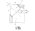
以下、本発明の好ましい実施の形態を図面を参照して説明する。図1〜図3は、本発明の第1実施例に係るV8型の内燃機関のシリンダブロック10を示している。このシリンダブロック10は、アルミダイキャストや鋳鉄等の金属により鋳造されるもので、所定のバンク角(この実施例では90度)をなす左右の各バンクLB,RBのそれぞれに、4個のシリンダ12がクランクシャフト14の軸方向に並んで形成されている。この実施例では、各シリンダ12を形成する別体のシリンダライナ16が鋳込まれている。また、シリンダブロック10には、シリンダ12を囲うようにウォータージャケット18が形成されているとともに、シリンダ12の下方にクランクシャフト14が回転可能に支持されている。
Hereinafter, preferred embodiments of the present invention will be described with reference to the drawings. 1 to 3 show a
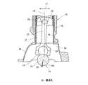
各シリンダ12にはピストン20が往復動可能に嵌合している。各ピストン20はコネクティングロッド22を介してクランクシャフト14のクランクピン24と連結されている。つまり、コネクティングロッド22の上端はピストンピン26を介してピストン20と連結されており、コネクティングロッド22の円筒状の下端部がクランクピン24に回転可能に嵌合している。図2にも示すように、クランクシャフト14は、複数のクランクピン24と、複数のジャーナル部28と、クランクピン24とジャーナル部28とを接続するバランスウエイト(クランクアーム)30と、を有し、ジャーナル部28には潤滑用の給油孔32が適宜形成されている。
A
シリンダブロック10におけるシリンダ12下方のピストンスカート部34には、クランクシャフト14を収容するクランクケース内に、隣り合うシリンダ12の下方空間を仕切るように、薄板状のバルクヘッド36が複数形成されている。各バルクヘッド36の下方にはクランクキャップ38がボルト(図示省略)により固定され、両者間にクランクシャフト14のジャーナル部28が軸受メタル39を介して回転可能に支持されている。なお、シリンダブロック10の小型・軽量化のために、隣り合うシリンダ間のピッチは非常に短く設定されており、隣り合うバルクヘッド36間のシリンダ下方の空間も非常に狭いものとなっている。
A plurality of thin plate-
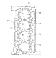
そして本実施例では、各バルクヘッド36に、隣り合うシリンダ12間の下方を連通する貫通孔40が貫通形成されている。機関運転中、内燃機関の回転部分を構成するクランクシャフト14のジャーナル部28を支持するバルクヘッド36には常に大きな変動荷重が作用し、特に、燃焼圧が最大となるピストン上死点近傍で最大荷重F0がコネクティングロッド22の中心線方向、つまりシリンダ中心線方向L0に作用する。このために、貫通孔40の周囲の中でも、最大荷重F0の作用方向(L0)と直交する部分αに応力集中を招き易い。そこで本実施例では、貫通孔40を、この最大荷重F0の作用方向を長手方向とする楕円形状に設定している。これにより、応力が集中し易い部分αの曲率半径が大きくなり、つまり曲率・湾曲が小さくなって、その応力集中を緩和することができる。従って、貫通孔の断面形状を真円形状とした場合に比して、応力集中を緩和することにより、強度不足を招くことなく貫通孔40の断面積を大きく確保して、気体を貫通孔40を通してスムースに隣りのシリンダ12の下方空間へ流動させることができ、ポンピングロス及びこれによるフリクションを大幅に低減することができる。
In this embodiment, each
また、一つの貫通孔40でクランクシャフト側からの入力による応力をスラスト−反スラスト方向L1でバランス良く負担するように、貫通孔40がスラスト−反スラスト方向L1でシリンダ12の中心位置つまりシリンダ中心線(L0)上に配置されている。更に、ポンピングロスの低減化を図るために、貫通孔40は、可能な限りシリンダ12に近いシリンダ寄り(燃焼室寄り)の位置、具体的にはシリンダライナ16の直ぐ下方位置に配置されている。
Further, the
但し、このようなシリンダライナ16の直ぐ下側部分、つまりシリンダ12の下端とバルクヘッド36の上端との接続部分には、ホーニング加工等によって段付き形状の段差部42が形成されている。このため、貫通孔40が段差部42にまたがるように、つまり段差部42と交差することとなり、段差部42と貫通孔40とが交差するスラスト−反スラスト方向の部分αで応力集中を招き易い。ここで本実施例によれば、貫通孔40をシリンダ中心線方向L0に長尺な断面楕円形状としているために、段差部42と交差するスラスト−反スラスト方向の部分αでは曲率・湾曲が緩くなり、段差部42における応力集中の緩和にも効果のあるものとなっている。
However, a
このような貫通孔40は、例えば鋳造時に同じ断面形状をもつ棒状の中子(ピン)を用いて鋳造と同時に一斉に形成することが可能である。但し、この場合、鋳造後に棒状の中子を抜くために、図2に示すようにシリンダブロック10の前後の壁部43の少なくとも一方に、複数の貫通孔40と同軸線上に補助貫通孔41が形成されることとなる。
Such through-
貫通孔の断面形状は、第1実施例のような楕円形状に限られず、楕円に近い形状であっても良い。例えば図4に示す第2実施例では、3つの真円の断面形状の円孔44A,44B,44Cを組み合わせて、最大荷重の作用方向であるシリンダ中心線方向L0を長手方向とする楕円に近い断面形状の貫通孔44を構成している。ここでは、相対的に大径の円孔44Aと、その両側の小径の2つの円孔44B,44Cとをシリンダ中心線方向L0に沿って配置し、かつ、互いに部分的にオーバーラップさせて、シリンダ中心線方向L0を長手方向とする略楕円形状の一つの貫通孔44を形成している。この第2実施例によれば、上記第1実施例とほぼ同様の作用効果が得られることに加え、貫通孔44を鋳造後にドリル加工等により形成することが可能であり、仕様・要求に応じた貫通孔44の形状・寸法の変更が容易である。なお、円孔の組み合わせは上記第2実施例に限られず、例えば複数の同径の円孔を組み合わせて略長円形の断面形状の貫通孔を構成しても良い。
The cross-sectional shape of the through hole is not limited to the elliptical shape as in the first embodiment, and may be a shape close to an elliptical shape. For example, in the second embodiment shown in FIG. 4, three
図5に示す第3実施例では、第1実施例に対して貫通孔の個数と位置を異ならせている。すなわち、2つの貫通孔46,46を、最大荷重の作用方向であるシリンダ中心線方向L0を中心として、スラスト−反スラスト方向L1に等間隔に並設している。各貫通孔46は、最大荷重作用方向L0を長手方向とする楕円形状をなしている。この場合、第1実施例とほぼ同様の作用効果が得られることに加え、総断面積の等しい一つの貫通孔を設けた場合に比して、貫通孔のシリンダ中心線方向L0の寸法を短縮化できる。
In the third embodiment shown in FIG. 5, the number and position of the through holes are different from those of the first embodiment. That is, the two through
図6に示す第4実施例では、一つの貫通孔48を、シリンダ中心線方向L0に対してスラスト−反スラスト方向L1で一方向、具体的にはバンク中心方向へオフセットさせている。また、貫通孔48の断面形状は、シリンダ中心線方向L0を長手方向とする楕円形状の楕円領域48Aと、この楕円領域48Aから強度的に余裕のあるシリンダ中心線L0から遠ざかる方向、つまり貫通孔48のオフセット方向へ拡大・拡張された拡張領域48Bと、を組み合わせた形状となっており、全体としては楕円に近い断面形状となっている。つまり、貫通孔48の楕円領域48Aをスラスト−反スラスト方向L1にオフセットさせるとともに、このオフセット方向に拡張領域48Bを楕円領域48Aの側方へ付帯形成している。
In the fourth embodiment shown in FIG. 6, one through
この第4実施例によれば、貫通孔48の楕円領域48Aにおける反オフセット側つまりシリンダ中心線L0寄りの部分の応力負担は大きくなるものの、オフセット方向寄りの部分の発生応力を小さくすることができ、このように強度的に余裕のある部分に拡張領域48Bを設けることで、強度不足を招くことなく貫通孔48全体の断面積を拡大して、ポンピングロスの大幅な低減化を図ることができる。
According to the fourth embodiment, although the stress burden on the counter-offset side in the
図7及び図8は、本発明を直列型の内燃機関のシリンダブロック10に適用した第5実施例を示している。この第5実施例の内燃機関では、クランクシャフト14の軸心14Aがシリンダ中心線方向L0に対してスラスト−反スラスト方向L1へオフセットしている。このため、ピストン上死点近傍における最大荷重F0の作用方向が、シリンダ中心線方向L0に対して傾斜したものとなっている。そして貫通孔50は、上記の最大荷重F0の作用方向を長手方向とする楕円(又は楕円に近い)形状をなしており、かつ、スラスト−反スラスト方向L1ではシリンダ中央位置、つまりシリンダ中心線L0上に配置されている。なお、図8に示すように、シリンダブロック10の前後の壁部の少なくとも一方に、第1実施例と同様の補助貫通孔41が複数の貫通孔50と同軸線上に形成されている。このような第5実施例においても、最大荷重F0に起因する応力集中を有効に緩和しつつ、貫通孔50の断面積を十分に確保してポンピングロスを大幅に低減することができる。
7 and 8 show a fifth embodiment in which the present invention is applied to a
10…シリンダブロック
12…シリンダ
14…クランクシャフト
16…シリンダライナ
20…ピストン
40,44,46,48,50…貫通孔
42…段差部
48A…楕円部
48B…拡張部
DESCRIPTION OF
Claims (4)
上記貫通孔を、ピストンの往復動に伴うクランクシャフト側からの最大荷重の作用方向を長手方向とする楕円の断面形状としたことを特徴とする内燃機関のシリンダブロック。 A plurality of cylinders in which the pistons reciprocate are formed, a thin plate-shaped bulkhead that supports the crankshaft rotatably and partitions the lower part between adjacent cylinders is formed, and a through hole is formed in the bulkhead In a cylinder block of an internal combustion engine,
The through hole, a cylinder block of an internal combustion engine, characterized in that the direction of action of the maximum load from the crank shaft side accompanying the reciprocation of the piston has an elliptical cross-sectional shape whose longitudinal direction.
上記貫通孔を、シリンダ中心線方向を長手方向とする楕円の断面形状としたことを特徴とする内燃機関のシリンダブロック。 A plurality of cylinders in which the pistons reciprocate are formed, a thin plate-shaped bulkhead that supports the crankshaft rotatably and partitions the lower part between adjacent cylinders is formed, and a through hole is formed in the bulkhead In a cylinder block of an internal combustion engine,
The through hole, a cylinder block of an internal combustion engine, characterized in that it has an elliptical cross-sectional shape of the cylinder center line direction is the longitudinal direction.
Priority Applications (1)
| Application Number | Priority Date | Filing Date | Title |
|---|---|---|---|
| JP2007289633A JP4968000B2 (en) | 2007-11-07 | 2007-11-07 | Internal combustion engine cylinder block |
Applications Claiming Priority (1)
| Application Number | Priority Date | Filing Date | Title |
|---|---|---|---|
| JP2007289633A JP4968000B2 (en) | 2007-11-07 | 2007-11-07 | Internal combustion engine cylinder block |
Publications (2)
| Publication Number | Publication Date |
|---|---|
| JP2009114985A JP2009114985A (en) | 2009-05-28 |
| JP4968000B2 true JP4968000B2 (en) | 2012-07-04 |
Family
ID=40782389
Family Applications (1)
| Application Number | Title | Priority Date | Filing Date |
|---|---|---|---|
| JP2007289633A Active JP4968000B2 (en) | 2007-11-07 | 2007-11-07 | Internal combustion engine cylinder block |
Country Status (1)
| Country | Link |
|---|---|
| JP (1) | JP4968000B2 (en) |
Family Cites Families (3)
| Publication number | Priority date | Publication date | Assignee | Title |
|---|---|---|---|---|
| JPH0191063U (en) * | 1987-12-09 | 1989-06-15 | ||
| JP2887996B2 (en) * | 1991-12-06 | 1999-05-10 | トヨタ自動車株式会社 | Cylinder block for internal combustion engine |
| JP4073737B2 (en) * | 2002-08-27 | 2008-04-09 | 本田技研工業株式会社 | Multi-cylinder engine crankcase communication structure |
-
2007
- 2007-11-07 JP JP2007289633A patent/JP4968000B2/en active Active
Also Published As
| Publication number | Publication date |
|---|---|
| JP2009114985A (en) | 2009-05-28 |
Similar Documents
| Publication | Publication Date | Title |
|---|---|---|
| JP4736778B2 (en) | Internal combustion engine and crank bearing structure thereof | |
| US20170089423A1 (en) | Crankshaft and method of balancing the same | |
| JP5674893B2 (en) | Crankshaft, bearing assembly, and large multi-cylinder two-stroke diesel engine | |
| US10352352B2 (en) | Machining oval cores in crankshafts | |
| JP4968000B2 (en) | Internal combustion engine cylinder block | |
| US7273030B2 (en) | Crankshaft support structure of internal combustion engine | |
| US9273604B2 (en) | Crankshaft | |
| JP2019108856A (en) | engine | |
| JP3339330B2 (en) | Cylinder block for internal combustion engine | |
| JP6569725B2 (en) | Multi-cylinder engine | |
| JP6586986B2 (en) | engine | |
| JP2010116974A (en) | Internal combustion engine | |
| CN106438085A (en) | Cylinder block of diesel engine | |
| US10156253B2 (en) | Connecting rod of engine | |
| JP6443546B2 (en) | Reciprocating engine crankshaft | |
| JP2010203518A (en) | Crankshaft structure | |
| JP7120159B2 (en) | cylinder block assembly | |
| JP4432553B2 (en) | Cylinder block | |
| JP2009257168A (en) | Engine and straddle-type vehicle including the same | |
| JP6881208B2 (en) | Cylinder block of V-type multi-cylinder internal combustion engine | |
| JP2015094246A (en) | Cylinder block of internal combustion engine | |
| JP7464345B2 (en) | Monoblock internal combustion engine | |
| JP2006348859A (en) | Cylinder block for internal combustion engine | |
| JP6614231B2 (en) | Multi-cylinder engine | |
| JP4396390B2 (en) | Cylinder block structure and manufacturing method thereof |
Legal Events
| Date | Code | Title | Description |
|---|---|---|---|
| A621 | Written request for application examination |
Free format text: JAPANESE INTERMEDIATE CODE: A621 Effective date: 20101027 |
|
| A977 | Report on retrieval |
Free format text: JAPANESE INTERMEDIATE CODE: A971007 Effective date: 20111006 |
|
| A131 | Notification of reasons for refusal |
Free format text: JAPANESE INTERMEDIATE CODE: A131 Effective date: 20111011 |
|
| A521 | Written amendment |
Free format text: JAPANESE INTERMEDIATE CODE: A523 Effective date: 20111205 |
|
| TRDD | Decision of grant or rejection written | ||
| A01 | Written decision to grant a patent or to grant a registration (utility model) |
Free format text: JAPANESE INTERMEDIATE CODE: A01 Effective date: 20120306 |
|
| A01 | Written decision to grant a patent or to grant a registration (utility model) |
Free format text: JAPANESE INTERMEDIATE CODE: A01 |
|
| A61 | First payment of annual fees (during grant procedure) |
Free format text: JAPANESE INTERMEDIATE CODE: A61 Effective date: 20120319 |
|
| FPAY | Renewal fee payment (event date is renewal date of database) |
Free format text: PAYMENT UNTIL: 20150413 Year of fee payment: 3 |
|
| R150 | Certificate of patent or registration of utility model |
Ref document number: 4968000 Country of ref document: JP Free format text: JAPANESE INTERMEDIATE CODE: R150 Free format text: JAPANESE INTERMEDIATE CODE: R150 |