JP4965970B2 - Method for fixing a scale to a carrier, scale formed therefor and carrier comprising this scale - Google Patents
Method for fixing a scale to a carrier, scale formed therefor and carrier comprising this scale Download PDFInfo
- Publication number
- JP4965970B2 JP4965970B2 JP2006298575A JP2006298575A JP4965970B2 JP 4965970 B2 JP4965970 B2 JP 4965970B2 JP 2006298575 A JP2006298575 A JP 2006298575A JP 2006298575 A JP2006298575 A JP 2006298575A JP 4965970 B2 JP4965970 B2 JP 4965970B2
- Authority
- JP
- Japan
- Prior art keywords
- scale
- carrier
- bonding
- ridges
- adhesive
- Prior art date
- Legal status (The legal status is an assumption and is not a legal conclusion. Google has not performed a legal analysis and makes no representation as to the accuracy of the status listed.)
- Active
Links
- 238000000034 method Methods 0.000 title claims description 19
- 239000000853 adhesive Substances 0.000 description 39
- 230000001070 adhesive effect Effects 0.000 description 39
- 230000003287 optical effect Effects 0.000 description 34
- 238000005259 measurement Methods 0.000 description 11
- 238000005304 joining Methods 0.000 description 7
- 239000010410 layer Substances 0.000 description 7
- 239000002241 glass-ceramic Substances 0.000 description 5
- 239000000463 material Substances 0.000 description 5
- 230000007246 mechanism Effects 0.000 description 5
- 239000006094 Zerodur Substances 0.000 description 4
- 238000010438 heat treatment Methods 0.000 description 4
- 239000004094 surface-active agent Substances 0.000 description 4
- 239000012790 adhesive layer Substances 0.000 description 3
- 239000000969 carrier Substances 0.000 description 3
- 238000011109 contamination Methods 0.000 description 3
- 239000007789 gas Substances 0.000 description 3
- 239000011521 glass Substances 0.000 description 3
- 239000000126 substance Substances 0.000 description 3
- IJGRMHOSHXDMSA-UHFFFAOYSA-N Atomic nitrogen Chemical compound N#N IJGRMHOSHXDMSA-UHFFFAOYSA-N 0.000 description 2
- 230000009471 action Effects 0.000 description 2
- 238000005452 bending Methods 0.000 description 2
- 230000008901 benefit Effects 0.000 description 2
- 230000008859 change Effects 0.000 description 2
- 230000008878 coupling Effects 0.000 description 2
- 238000010168 coupling process Methods 0.000 description 2
- 238000005859 coupling reaction Methods 0.000 description 2
- 150000002500 ions Chemical class 0.000 description 2
- 238000003754 machining Methods 0.000 description 2
- 238000012423 maintenance Methods 0.000 description 2
- 241000217377 Amblema plicata Species 0.000 description 1
- 241000669069 Chrysomphalus aonidum Species 0.000 description 1
- 238000005411 Van der Waals force Methods 0.000 description 1
- 208000000260 Warts Diseases 0.000 description 1
- 238000004026 adhesive bonding Methods 0.000 description 1
- 229910052782 aluminium Inorganic materials 0.000 description 1
- XAGFODPZIPBFFR-UHFFFAOYSA-N aluminium Chemical compound [Al] XAGFODPZIPBFFR-UHFFFAOYSA-N 0.000 description 1
- 238000013459 approach Methods 0.000 description 1
- 230000015572 biosynthetic process Effects 0.000 description 1
- 239000003795 chemical substances by application Substances 0.000 description 1
- 230000001143 conditioned effect Effects 0.000 description 1
- 238000005336 cracking Methods 0.000 description 1
- 230000032798 delamination Effects 0.000 description 1
- 230000001419 dependent effect Effects 0.000 description 1
- 238000013461 design Methods 0.000 description 1
- 230000006866 deterioration Effects 0.000 description 1
- 238000009826 distribution Methods 0.000 description 1
- 230000005611 electricity Effects 0.000 description 1
- 238000005516 engineering process Methods 0.000 description 1
- 230000003628 erosive effect Effects 0.000 description 1
- 230000005284 excitation Effects 0.000 description 1
- 239000001307 helium Substances 0.000 description 1
- 229910052734 helium Inorganic materials 0.000 description 1
- SWQJXJOGLNCZEY-UHFFFAOYSA-N helium atom Chemical compound [He] SWQJXJOGLNCZEY-UHFFFAOYSA-N 0.000 description 1
- 230000006872 improvement Effects 0.000 description 1
- 239000007788 liquid Substances 0.000 description 1
- 238000001459 lithography Methods 0.000 description 1
- 238000010002 mechanical finishing Methods 0.000 description 1
- 229910052751 metal Inorganic materials 0.000 description 1
- 239000002184 metal Substances 0.000 description 1
- 238000003801 milling Methods 0.000 description 1
- 229910052757 nitrogen Inorganic materials 0.000 description 1
- 239000003973 paint Substances 0.000 description 1
- 230000000737 periodic effect Effects 0.000 description 1
- 230000002093 peripheral effect Effects 0.000 description 1
- 238000005498 polishing Methods 0.000 description 1
- 230000036316 preload Effects 0.000 description 1
- 238000003825 pressing Methods 0.000 description 1
- 230000008569 process Effects 0.000 description 1
- 238000007789 sealing Methods 0.000 description 1
- 238000000926 separation method Methods 0.000 description 1
- 201000010153 skin papilloma Diseases 0.000 description 1
- 230000003068 static effect Effects 0.000 description 1
- 230000001502 supplementing effect Effects 0.000 description 1
- 230000008961 swelling Effects 0.000 description 1
- 230000009466 transformation Effects 0.000 description 1
- 230000007704 transition Effects 0.000 description 1
Images


Classifications
-
- G—PHYSICS
- G01—MEASURING; TESTING
- G01D—MEASURING NOT SPECIALLY ADAPTED FOR A SPECIFIC VARIABLE; ARRANGEMENTS FOR MEASURING TWO OR MORE VARIABLES NOT COVERED IN A SINGLE OTHER SUBCLASS; TARIFF METERING APPARATUS; MEASURING OR TESTING NOT OTHERWISE PROVIDED FOR
- G01D5/00—Mechanical means for transferring the output of a sensing member; Means for converting the output of a sensing member to another variable where the form or nature of the sensing member does not constrain the means for converting; Transducers not specially adapted for a specific variable
- G01D5/26—Mechanical means for transferring the output of a sensing member; Means for converting the output of a sensing member to another variable where the form or nature of the sensing member does not constrain the means for converting; Transducers not specially adapted for a specific variable characterised by optical transfer means, i.e. using infrared, visible, or ultraviolet light
- G01D5/32—Mechanical means for transferring the output of a sensing member; Means for converting the output of a sensing member to another variable where the form or nature of the sensing member does not constrain the means for converting; Transducers not specially adapted for a specific variable characterised by optical transfer means, i.e. using infrared, visible, or ultraviolet light with attenuation or whole or partial obturation of beams of light
- G01D5/34—Mechanical means for transferring the output of a sensing member; Means for converting the output of a sensing member to another variable where the form or nature of the sensing member does not constrain the means for converting; Transducers not specially adapted for a specific variable characterised by optical transfer means, i.e. using infrared, visible, or ultraviolet light with attenuation or whole or partial obturation of beams of light the beams of light being detected by photocells
- G01D5/347—Mechanical means for transferring the output of a sensing member; Means for converting the output of a sensing member to another variable where the form or nature of the sensing member does not constrain the means for converting; Transducers not specially adapted for a specific variable characterised by optical transfer means, i.e. using infrared, visible, or ultraviolet light with attenuation or whole or partial obturation of beams of light the beams of light being detected by photocells using displacement encoding scales
- G01D5/34707—Scales; Discs, e.g. fixation, fabrication, compensation
Description
本発明は担持体にスケールを固定する方法に関する。 The present invention relates to a method for fixing a scale to a carrier.
二つの機械部分の相対位置を測定するために、機械部分の一方にスケールを固定し、互いに可動な他方の機械部分に走査ユニットを固定しなければならない。位置測定の際、スケールの目盛を走査ユニットにより走査する。 In order to measure the relative position of the two machine parts, the scale must be fixed to one of the machine parts and the scanning unit to the other machine part movable relative to each other. When the position is measured, the scale is scanned by the scanning unit.
スケールを担持体に固定する場合、二つの根本原理がある。第一の根本原理にあっては、スケールが担持体に対して温度変化がある場合自由に延びることができるようにスケールを担持体に固定する。この場合固定は測定方向で移動可能な固定部材あるいは弾性的接着層を用いて行われる。 There are two basic principles when fixing the scale to the carrier. In the first basic principle, the scale is fixed to the carrier so that the scale can freely extend when there is a temperature change with respect to the carrier. In this case, the fixing is performed using a fixing member or an elastic adhesive layer movable in the measuring direction.
第二の根本原理にあっては、スケールを担持体に堅く固定する。この場合担持体とスケールは線膨張係数が同じ材料でできている。担持体とスケールが異なる材料でできている場合、スケールには担持体の温度特性が強制される。この固定は第二根本原理の場合、固く硬化する希薄な接着層あるいはオプティカルコンタクトを介して行われる。 In the second basic principle, the scale is firmly fixed to the carrier. In this case, the carrier and the scale are made of a material having the same linear expansion coefficient. When the support and the scale are made of different materials, the scale is forced to have temperature characteristics of the support. In the case of the second basic principle, this fixing is performed through a thin adhesive layer or optical contact that is hardened.
高度に精密な位置測定を行うためには、線膨張係数がほとんど無視できるガラスあるいはガラスセラミックでできたスケールを使用するのが好ましい。このスケールは加工がし易く、従ってこの場合特許文献1に記載されているようにオプティカルコンタクトを対向面に対して使用する。 In order to perform highly precise position measurement, it is preferable to use a scale made of glass or glass ceramic whose linear expansion coefficient is almost negligible. This scale is easy to process, so in this case an optical contact is used against the opposing surface as described in US Pat.
スケールのオプティカルコンタクトにおける問題点は、結合が汚染あるいは気泡の形成により容易に解除してしまうことがあることである。さらに結合面の高い平面度が必要であり、これには高額なコストがかかる。この問題は相対的に面が広いスケールの場合に増幅されて生じる。この理由からスケールのオプティカルコンタクトは
一般に実施されなかった。
本発明の課題は、この問題を取り除く方法を提供することにある。 It is an object of the present invention to provide a method that eliminates this problem.
この課題は、請求項1による方法により解決される。
This problem is solved by the method according to
本発明の別の課題は、安定して固定されたスケールを備えた担持体を提供することである。 Another object of the present invention is to provide a carrier having a scale that is stably fixed.
この課題は請求項7による担持体を備えていることにより解決される。
This problem is solved by providing the carrier according to
さらに本発明は請求項18の特徴を備えたスケールに関する。 The invention further relates to a scale having the features of claim 18.
本発明の有利な実施例は従属請求項に示してある。 Advantageous embodiments of the invention are given in the dependent claims.
本発明によって、できるだけ大きな力を保持力として加え、同時にではあるがオプティカルコンタクトの短所を回避することにより、また多数の互いに分離したオプティカルコンタクト面を形成することにより、オプティカルコンタクトの達成されうる長所が利用される。 The present invention has the advantages that optical contact can be achieved by applying as much force as holding force and avoiding the disadvantages of optical contact at the same time, and by forming a number of optical contact surfaces separated from each other. Used.
汚染あるいは擦り傷により局所的に解除した接合結合(Bondverbindung)の解除部は、本発明によるオプティカルコンタクト面の分離により区画される。解除は一般に遮断された接合結合によっては広がらない。 The release portion of the bond bond that has been locally released due to contamination or scratches is defined by the separation of the optical contact surface according to the present invention. Release generally does not spread by a blocked bond.
さらに妨げとなる媒質が、少なくとも一つの外側に案内される管路を通って流出するので、良好なスケールの平面度が得られる。 Furthermore, the hindering medium flows out through at least one outwardly guided conduit, so that good scale flatness is obtained.
本発明の実施例を図に基づき詳しく説明する。 Embodiments of the present invention will be described in detail with reference to the drawings.
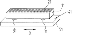
図1〜3を基にして第一実施例を説明する。この場合ガラスあるいはガラスセラミック(例えばZERODUR)でできたスケール11は測定目盛21を備えている。測定目盛21は位置測定するためにX方向で走査可能なインクリメンタル目盛である。測定目盛21は、既知の方法で高度に精密で干渉の位置測定を行なうために使用される、反射する振幅ジッターあるいは位相ジッターであってもよい。スケール11はベッセル点の領域内において隆起部31を備え、この隆起部は担持体51の対向面41に取付けるための支持部として使用されている。同様にして担持体51はガラスあるいはガラスセラミック(例えばZERODUR)でできているのが好ましい。
A first embodiment will be described with reference to FIGS. In this case, the
担持体51の対向面41と相対する隆起部31の表面61、ならびに対向面41は清潔でありかつ高度に研磨された表面である。必要な表面の品質は機械的な研磨仕上げあるいは化学機械的仕上げにより達せられる。
The
スケール11の隆起部31は、隆起部31の領域がカバーされ、材料が隆起部31の周囲で腐食して除去されることによって、公知の構造方式により製造されるのが好ましい。従って隆起部31はスケール11において構造一体的に形成されている。
The raised
スケール11と担持体51の結合は、隆起部31の表面61を担持体51の対向面41と接合することにより行なわれる。本発明の根底をなしている接合の基盤は、その状態が原子の結合力の届く範囲内に達する場合に、清潔で圧着可能でかつ研磨された表面が互いに付着するような接着である。さらに接合は光学的接触あるいは非接着ボンディングとも呼ばれる。隆起部の表面61は、この隆起部が担持体51の対向面41と接合接続を行なうための接合可能な表面61を備えるように形成されている。
The
この接合はオプティカルコンタクトとも呼ばれる直接接合(直接接合あるいは直接接触)であってもよい。直接接合の場合、接合作用は熱の影響により、あるいは界面活性剤を塗布することにより高めることができる。界面活性剤を用いた直接接合により、良好な接合強度が相対的に低い温度の場合でも得られる。特殊な界面活性剤の様式は結晶化する液体を提供することである。さらにこの接合方式は低温接合技術とも呼ばれ、かつインターネットを介して公開されている、明確に関連したキャロル・クリック、レオ・ギロイ及びデーブ・バンダープール著の「SCHOTT Low Temperature Bonding for Precision Optics」という題名のショット社の論文で解説されている。LTB方式の場合、スケール11と担持体51は、各々線膨張係数がゼロに近いガラスセラミック、特にZERODURでできている。
This bonding may be direct bonding (direct bonding or direct contact) also called an optical contact. In the case of direct bonding, the bonding action can be enhanced by the influence of heat or by applying a surfactant. By direct bonding using a surfactant, good bonding strength can be obtained even at relatively low temperatures. A special surfactant mode is to provide a liquid that crystallizes. This bonding method is also called low temperature bonding technology and is publicly available via the Internet called "SCHOTT Low Temperature Bonding for Precision Optics" by the clearly related Carol Crick, Leo Gilroy and Dave Vanderpool. It is explained in the title Schott paper. In the case of the LTB method, the
さらに接合は電気化学的接合であり、この電気化学的接合において、互いに接続されるべきスケール11と担持体51の表面61,41には、金属の電気的に導通性のある補助層、例えばアルミニウムが、隆起部31と対向面41の間の中間層として付与されている。
この補助層は蒸着された層であってもよい。電気化学的接合の場合、補助層と担持体51の間には応力がかかっており、従って補助層のイオンは担持体内に流れ、および/または担持体51のイオンは補助層内に流れる。かかっている応力は静電気の引力であり、この静電気の引力によりスケールと担持体の間で原子の接触が生じる。
Further, the joining is an electrochemical joining. In this electrochemical joining, the
This auxiliary layer may be a deposited layer. In the case of electrochemical bonding, stress is applied between the auxiliary layer and the
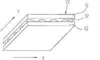
多次元の位置測定を行なうために、二次元の測定目盛22を備えたスケール12を使用することが増えている。この場合相対的に拡大されたスケール12(例えば40cm×40cm)を、機械部分52の面42に固定する。スケール12を固定しなければならない機械部分52は、線膨張係数がゼロに近いガラスセラミック(例えばZERODUR)でできているリソグラフィック装置の場合に特に、本発明が使用可能であるのは有利である。二次元の測定目盛22を備えたスケールを用いたこのような機械はここにおいて関連する特許文献2に説明されている。
In order to perform multidimensional position measurement, the use of a
この場合必要とされる約1m×2mの測定領域をカバーするために、多数のスケール12を例えば1m×2mの機械面52上で二次元で並んでモザイク状に固定しなければならないことが必要であることがある。特に光電的に走査される測定目盛22を備えたスケール12は、必要な精密さで、すなわち約40cm×40cmの大きさで仕上げ可能である。これらのスケール12は各々、本発明によればあとで述べる図で示すように担持体52に固定される。
In order to cover the required measurement area of about 1 m × 2 m in this case, it is necessary to fix a large number of
このように固定する場合に前述の接合方法を使用する。 In the case of fixing in this way, the above-described joining method is used.
図4及び5には、二次元の測定目盛22−交差ジッターとも呼ばれる−を備えたスケール12が模範的に示してある。担持体52の方に向いたスケール12の面には、接合可能な表面62を備えた隆起部32が形成されている。これらの隆起部32は二次元空間的に配分された状態で、言い換えれば規則的な走査パターンで幾何学的かつ一様に配置されているかあるいは統計学的に配置されているかのどちらかの状態で設けられているのが好ましい。隆起部32は各々円形状に形成されており、30mmよりは小さく、一般的には200μm〜4mmの直径を備え、スケール12の厚さよりも好ましくは小さい相互間隔を備えており、この場合したがって相互間隔、すなわち縁部間隔は図11及び16では4mmである。隆起部32の高さは有利な方法では10nmであり、好適な値は特に20nm〜50μmである。隆起部32の表面62の平面度(うねり)は約10mmの直径上では500nm以下の範囲にあり、一般的には30nmから10mmまでの範囲にある。一方接合面として形成された隆起部32の表面62は、共通平面内にある。スケール12の厚さに関する一般的値は1〜15mmである。隆起部32の直径が小さく、相互間隔が小さいほど、隆起部32の高さはいっそう低く仕上げられている。
4 and 5 exemplarily show a
少なくとも空間的な隆起部32の分配は、隆起部32の間で−XY平面に関してスケール12の縁部まで達する開口管路200が生じるように行なわれねばならない。この方法により、表面活性剤は接合後スケール12と担持体52の間の空域から容易に抜け出すことができる。さらに気泡もスケールの面にわたり開口管路200を介して容易に抜け出すことができ、それにより接合強度は高まり、ならびに良好なスケール12の平面度が確実に得られる。
The distribution of at least the
隆起部32はイボ状突起の様式を形成し、かつ開口管部200を形成する縁部−その傍らにある窪みへの移行部−が丸みを付されているように形成されている。これにより接合されるべき表面62はより良好に洗浄され、場合によっては表面活性化される。別の長所は剥離に関する不都合な作用点が防止され、材料が割れる危険が著しく下がることにある。
The raised
メンテナンスの際、スケール12と担持体52の中間空域内で、担持体52あるいはスケール12内の少なくとも一つの(図示していない)孔を介して媒体、例えば圧縮空気が導入され、これにより圧力が上昇し、スケール12と担持体52が互いに押し合うことにより、接合結合は解除される。
During maintenance, a medium such as compressed air is introduced into the intermediate air space between the
特に(例えば図6と7に示した)担持体53から突出するスケール13の場合、振動励起によりスケール13の縁部領域の交互の剥離と再度のオプティカルコンタクトを生じる危険がある。この現象により、突出するスケール領域の短周期的長さ異常の変化は予測不能になる。これを回避するためには、別の手段が有利である。したがってスケール11〜15を保持するための他のロック機構(Sicherung)を担持体51〜55に設けることができる。この別のロック機構は、バネ、ブラケット、磁気保持手段、静電気によるロック機構あるいは真空保持機構でもよく、あるいは油膜もしくは接着方式のような付着保持手段を使用してもよい。この別のロック機構は、少なくとも絞り結合の領域において、従ってスケール13および/または担持体53の縁部領域において、すなわちスケール13と担持体53のオーバーラップ部の縁部領域において有効である。
In particular, in the case of the
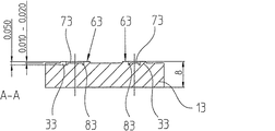
以下にオプティカルコンタクト部を補充するために、図6〜19に基づいた特に有利な接着結合を説明する。この場合不連続のオプティカルコンタクト面63の予荷重により、特にスケール13と担持体53の結合の縁部領域においては、接着剤7を用いて結合相手13と53の間の圧力が高められる。
In the following, a particularly advantageous adhesive connection according to FIGS. 6 to 19 will be described for supplementing the optical contact part. In this case, due to the preload of the discontinuous
接着剤7を用いたロック機構により、スケール13が離れることやなくなることは、例えば間違って接触した場合に、組立作業により防止されている。
The
この場合接着層により場合によればスケール13の最小変形が局所的に発生する。位置と平面度は依然として精密であり、かつオプティカルコンタクト接合により広範囲に及んでズレもない。
In this case, the minimum deformation of the
図6は担持体53にわたり縁部領域に沿って突出しているスケール13を示す。スケール13の円形の隆起部33の幾つかは接着箇所を別に備えており、隆起部の中から一つを図7において横断面図で示してある。オプティカルコンタクト接合された隆起部32と接着剤7により別に保護された隆起部33を区別するために、これらは異なる関連標識を備え、接着剤7により保護された隆起部33は図6において黒で示してある。接着剤7により別に保護された隆起部33の場合、円形のオプティカルコンタクト面63の内側には円形の接着面73があり、この円形の接着面は接着剤禁止部としての溝状の窪み部83によりオプティカルコンタクト面63から分離している。これにより接着剤7が塗布された場合に前記円形の接着剤がオプティカルコンタクト面63に達することは回避される。
FIG. 6 shows the
一目瞭然である理由から、目盛は示していない。オプティカルコンタクト面63に対向して低い位置にある領域、すなわち接着面73と窪み部83の製造は例えばリソグラフィ法で行われる。代替え手段としては、機械加工、フライス加工、あるいは相応する材質の場合にはレーザー加工も可能である。
The scale is not shown for reasons that are self-explanatory. A region at a low position facing the
接着面73と接着剤7のEモジュールは、(接着剤7の収縮により条件付けられるが)接着剤硬化後の引張り力によるスケール13の曲げ変形を、必要であるができるだけ小さい大きさに維持するように、無条件で必要不可欠な大きさに維持される。
The E module of
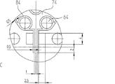
さらに看過され易く重要ではない短周期性のスケール13の撓みは、接着面73の大きさが同じである場合、図8及び9において各々右側に示した、オプティカルコンタクト面63ならびに接着面73の長円形の形状により得られる。構造的な設計には関係なく、硬化した際の接着剤により及ぼされる力は、可能な限り短い支持間隔でもって、かつ可能な限り周囲で捕捉されることが重要である。これにより接着面73を取囲む隆起部あるいはオプティカルコンタクト面63は保証されている。
Further, the bending of the short-
オプティカルコンタクト及び接着の保証の作業手順は、以下のように行われる。
−スケール13が担持体53と接触する。
−スケール13を担持体53に合わせて調節し、この場合この状態でのオプティカルコンタクトを防ぐために、例えば孔93を経由して、ガス、例えば空気をスケール13と担持体53の中間空域内に収容することにより、調節を楽にする。
−担持体53にスケール13を押圧し、同時にスケール13を調節された状態でオプティカルコンタクトする。この場合押圧はスケール13と担持体53の中間空域内で真空(真空にすること)を発生させることにより行われる。
−担持体53内の孔93を経由して接着面73に接着剤7を塗布する。
The procedure for assuring the optical contact and adhesion is performed as follows.
The
-Adjusting the
-The
The adhesive 7 is applied to the
例えば空気の湿度を変化させることにより、接着剤7が収縮するかあるいは膨れることによる測定運転中のスケール13の形状変化を防止するために、孔93を接着剤の塗布後に気密に閉鎖することができる。代替え案としては、孔93を経由してオプティカルコンタクトが行われた後に、接着剤7の劣化を防ぐために、ガス(例えば窒素あるいはヘリウム)を一定の湿度でもって、スケール13と担持体53の中間空域内に案内し、したがって接着面73まで案内してもよい。
For example, in order to prevent the change in the shape of the
適切な接着剤7を使用する場合、メンテナンスの際の接着が保証されるオプティカルコンタクトの結合は、例えば接着剤7を加熱することにより、あるいは一定の波長の光を使用したクラックにより、あるいは化学薬品により解除可能である。加熱による解除の場合、接着面73を局所的に加熱するために、加熱部材を孔93内に挿入してもよい。化学的解除剤を使用した解除の場合、加熱は同様に孔93を介して行うことができる。代替え案あるいは別の案として、オプティカルコンタクトの結合を解除するために、孔93を経由してスケール13と担持体53の中間空域内で圧力を上昇させてもよい。
When an
以下に述べる図10〜19による実施例は接着剤7の塗布を軽減する有利な変形を示す。 The examples according to FIGS. 10 to 19 described below show an advantageous variant for reducing the application of the adhesive 7.
図10〜14による実施例では、接着剤7はスケール14あるいは担持体54の縁部から配量され、かつ毛細管力により接着面74内に引張られる。突起状の隆起部34の表面64と接着面74の間の溝状かあるいは条溝形状の窪み部84により、オプティカルコンタクト面64への接着コンタクトは防止される。
In the embodiment according to FIGS. 10 to 14, the adhesive 7 is dispensed from the edge of the
配量管路のすぐ近くにおいて、ならびに接着面74により形成されている接着領域の内側においてオプティカルコンタクト面64により支持することが保証されている。窪み部84は接着剤7がオプティカルコンタクト面64に接触するのを防止する(オプティカルコンタクトは入り込む接着剤7により阻止される)。
It is guaranteed to be supported by the
図15〜19による実施例では、担持体55において切欠き部95が設けられており、この切欠き部は接着面75に接着剤7を塗布するために使用される。接着剤7は毛細管力により切欠き部95から出発して接着面75まで引張られる。これによりスケール15の突出した領域での収縮した接着点は回避され、接着剤7は突出するスケール15を外すことはない。
In the embodiment according to FIGS. 15 to 19, a
全ての実施例において担持体55は縁部に向ってテーパー部100を備えていてもよい。従って担持体55は剛性が低く、突出するスケール15の変形に同時に影響を及ぼす。これにより縁部領域内での解除の危険は軽減する。実施例は図15に示してある。
In all embodiments, the
担持体51〜55の縁部領域のテーパー部100は一緒に使用可能であり、かつオプティカルコンタクトの安定性を改善するための他の接着固定部が無くても使用可能である。
The
隆起部33〜35により形成され、接着面73〜75を取囲むサポート面63〜65は、接着面73〜75の周囲でできる限り対称に設けられるべきである。これにより同様に表面の部分的変形はわずかに維持される。
The support surfaces 63 to 65 formed by the raised
突起状の隆起部31〜35は、外側まで通じている管路200により、さらに平坦なオプティカルコンタクト面内で互いに分離されている(中間空域からの空気の漏洩、オプティカルコンタクト作用の改善)。接着剤止め用窪み部83,84,85があってもあるいは無くても、面/突起部/条溝の様々な混合が可能である。
The protruding
接合結合部を外部の影響及び異物混入(Unterkriechen)から守るために、接合結合部を作った後、スケール11〜15と、担持体51〜55との間の中間空域は、スケール11〜15の周囲の縁部をシールすることによりシールすることができる。この目的で塗料あるいは接着剤を使用することができる。さらに中間空域が媒質を用いてあふれることにより保護がなされる。このために例えば一定の特性のガスが隆起部31〜35の間の空域内へ、従って管路200内へ収容されかつその中を貫流する。
In order to protect the joint joint from external influences and foreign matter contamination (Unterkriechen), the intermediate air space between the
先に示した実施例の場合、互いに間隔をおいて設けられた隆起部31〜35は、突起の形状でスケール11〜15に形状一体に形成されている。さらに隆起部31〜35は代替え的かあるいは付加的に担持体51〜55にも形成されていてもよい。さらに隆起部31〜35はスケール11〜15あるいは担持体51〜55上に取り付けられかつ構造を与えられた被膜であってもよい。
In the case of the above-described embodiment, the raised
隆起部31〜35の形状と配設は図示した実施例に限定されない。
The shape and arrangement of the raised
少なくともほぼ正方形かあるいは円形のスケールにおいて、ただ三つの隆起部が平面内に分配されて設けられていることにより、隆起部は動的に一定の受台を形成する。 By providing only three ridges distributed in a plane, at least on a substantially square or circular scale, the ridges dynamically form a constant cradle.
本発明の接合方法にはすべて、ファンデルワールス力により互いに引き合うことができるか(直接接合)、あるいは関節結合の様式でわずかな原子位置を構成することにより、原子の結合を作れるように(LTD,陽極接合)、結合すべき表面61〜65,41〜45がほんのわずかな原子間間隔まで互いに接近することが共通である。
All of the joining methods of the present invention can be attracted to each other by van der Waals forces (direct joining), or can form atomic bonds by constructing a few atomic positions in an articulated manner (LTD , Anodic bonding), it is common for the
図中に記入した寸法はmmで与えられており、例として大きさを示す。 The dimensions entered in the figure are given in mm and indicate the size as an example.
Claims (10)
接合結合が二次元パターンで配分された状態で設けられており、互いに間隔をおいて設けられた多数のスケール(11〜15)の表面領域(61〜65)で行われており、これらの表面領域が各々管路(200)により互いに分離していることを特徴とする方法。 In the method for fixing the scale (11-15) to the carrier (51-55) by producing a joint joint between the scale (11-15) and the carrier (51-55),
Bonded bonds are provided in a two-dimensional pattern and are performed on the surface areas (61-65) of a number of scales (11-15) spaced apart from each other. A method characterized in that the regions are separated from each other by lines (200).
接合が二次元パターンで配分された状態で設けられており、互いに間隔をおいて設けられた多数のスケール(11〜15)の表面領域(61〜65)で行われており、これらの表面領域が各々管路(200)により互いに分離していることを特徴とする担持体。 A bearing member provided with a scale, in bearing member scale (11 to 15) are fixed by bonding in carrier (51 to 55),
The joints are provided in a two-dimensional pattern and are performed on the surface areas (61-65) of a number of scales (11-15) spaced apart from each other. Are separated from each other by pipes (200).
固定面が二次元パターンで配分された状態で設けられており、互いに間隔をおいて設けられた隆起部(3,30)により形成されており、隆起部(3,30)が各々、担持体(5,50)の対向面(4,40)と接合結合を作るための接合可能な表面(6,60)を備えていることを特徴とするスケール。 In a scale having a fixing surface for fixing to a carrier (5, 50),
Fixing surface is provided in a state of being distributed in a two-dimensional pattern is formed by ridges spaced apart from each other (3, 30), raised portions Takashi (3,30) are each supported A scale characterized in that it comprises a bondable surface (6, 60) for making a bonded bond with the opposing surface (4, 40) of the body (5, 50).
Applications Claiming Priority (4)
| Application Number | Priority Date | Filing Date | Title |
|---|---|---|---|
| DE102005053088.5 | 2005-11-04 | ||
| DE200510053088 DE102005053088A1 (en) | 2005-11-04 | 2005-11-04 | Scale attaching method for use in support, involves providing surfaces with adhesives between scale and support, and forming wringing surfaces in direct proximity to dosing channel, where wringing surfaces are separated from one another |
| DE102006017708.8 | 2006-04-15 | ||
| DE200610017708 DE102006017708A1 (en) | 2006-04-15 | 2006-04-15 | Scale attaching method for use in support, involves providing surfaces with adhesives between scale and support, and forming wringing surfaces in direct proximity to dosing channel, where wringing surfaces are separated from one another |
Publications (3)
| Publication Number | Publication Date |
|---|---|
| JP2007127649A JP2007127649A (en) | 2007-05-24 |
| JP2007127649A5 JP2007127649A5 (en) | 2009-11-26 |
| JP4965970B2 true JP4965970B2 (en) | 2012-07-04 |
Family
ID=37722726
Family Applications (1)
| Application Number | Title | Priority Date | Filing Date |
|---|---|---|---|
| JP2006298575A Active JP4965970B2 (en) | 2005-11-04 | 2006-11-02 | Method for fixing a scale to a carrier, scale formed therefor and carrier comprising this scale |
Country Status (3)
| Country | Link |
|---|---|
| EP (1) | EP1783463B1 (en) |
| JP (1) | JP4965970B2 (en) |
| ES (1) | ES2535851T3 (en) |
Families Citing this family (7)
| Publication number | Priority date | Publication date | Assignee | Title |
|---|---|---|---|---|
| JP5162800B2 (en) * | 2009-03-24 | 2013-03-13 | 株式会社ミツトヨ | Linear scale |
| DE102009002142A1 (en) | 2009-04-02 | 2010-10-07 | Dr. Johannes Heidenhain Gmbh | An assembly with a scale attached to a support and method of holding a scale on a support |
| DE102009047120A1 (en) | 2009-11-25 | 2011-05-26 | Dr. Johannes Heidenhain Gmbh | Arrangement with a scale attached to a support |
| EP3023742B1 (en) * | 2014-11-19 | 2017-01-11 | Dr. Johannes Heidenhain GmbH | Assembly comprising a measurement scale attached to a support |
| DE102016201088A1 (en) | 2016-01-26 | 2017-07-27 | Dr. Johannes Heidenhain Gmbh | Method for processing a material measure |
| US11491737B2 (en) * | 2018-09-25 | 2022-11-08 | Raytheon Company | Robust method for bonding optical materials |
| JP7221433B1 (en) | 2022-02-03 | 2023-02-13 | 株式会社光学技研 | Optical element and method for manufacturing optical element |
Family Cites Families (7)
| Publication number | Priority date | Publication date | Assignee | Title |
|---|---|---|---|---|
| JPH08145609A (en) * | 1994-11-21 | 1996-06-07 | Sony Magnescale Inc | Position detector |
| JPH08247791A (en) * | 1995-03-09 | 1996-09-27 | Olympus Optical Co Ltd | Optical microlinear encoder |
| US5669997A (en) * | 1995-07-13 | 1997-09-23 | Hughes Danbury Optical Systems, Inc. | Method of bonding optical members together |
| JPH1090576A (en) * | 1996-09-17 | 1998-04-10 | Fuji Photo Film Co Ltd | Fixing structure of optical member |
| DE19755482A1 (en) * | 1997-12-13 | 1999-06-17 | Zeiss Carl Fa | Connected body |
| JP3517185B2 (en) * | 2000-07-19 | 2004-04-05 | 株式会社ミツトヨ | Scale member, manufacturing method thereof, and displacement meter using the same |
| DE10153147A1 (en) * | 2001-10-27 | 2003-05-08 | Zeiss Carl | Method of applying a scale to a support |
-
2006
- 2006-09-09 ES ES06018925.5T patent/ES2535851T3/en active Active
- 2006-09-09 EP EP20060018925 patent/EP1783463B1/en active Active
- 2006-11-02 JP JP2006298575A patent/JP4965970B2/en active Active
Also Published As
| Publication number | Publication date |
|---|---|
| ES2535851T3 (en) | 2015-05-18 |
| EP1783463B1 (en) | 2015-04-15 |
| JP2007127649A (en) | 2007-05-24 |
| EP1783463A1 (en) | 2007-05-09 |
Similar Documents
| Publication | Publication Date | Title |
|---|---|---|
| JP4965970B2 (en) | Method for fixing a scale to a carrier, scale formed therefor and carrier comprising this scale | |
| US7707739B2 (en) | Method for attaching a scale to a carrier, a scale, and carrier having a scale | |
| JP5586595B2 (en) | Optical interference type pressure sensor | |
| US5979238A (en) | Strip-shaped resiliently flexible measuring tape for length--or angle-measuring devices | |
| JP5436658B2 (en) | Device having a scale fixed to a carrier and method for holding a scale on a carrier | |
| JP5579024B2 (en) | Arrangement apparatus having a ruler fixed to a holding body | |
| EP1078227B1 (en) | An optically addressed sensing system | |
| JP2011069813A (en) | Length measuring device | |
| WO2021074054A1 (en) | Method for connecting an attachment to a main body of an optical element and optical element | |
| JP2011027862A (en) | Bonded optical element | |
| US6099193A (en) | Composite body | |
| JP2011028239A (en) | Cemented optical element | |
| US11768322B2 (en) | Grating part and manufacturing method thereof | |
| US6227754B1 (en) | Composite body | |
| CN1959540B (en) | Method for attaching a scale to a carrier, a scale, and carrier having a scale | |
| JP2000035369A (en) | Pressure sensor and its manufacturing method | |
| JP5653690B2 (en) | Pellicle frame and pellicle | |
| CA2296090C (en) | Pressure sensor and a method of manufacturing the same | |
| JPH11248871A (en) | Positioning table | |
| JP5163041B2 (en) | Optical element fixing device and manufacturing method thereof | |
| JP2552187B2 (en) | High-precision bonding method | |
| JP2008241838A (en) | Compound lens and method of manufacturing the same | |
| Erbe | Basic considerations for circumferential adhesive bonds in order to reduce lens deformations | |
| US20080100815A1 (en) | Arrangement of two connected bodies | |
| JP2001062694A (en) | Recessed plate and application thereof |
Legal Events
| Date | Code | Title | Description |
|---|---|---|---|
| A521 | Request for written amendment filed |
Free format text: JAPANESE INTERMEDIATE CODE: A523 Effective date: 20091007 |
|
| A621 | Written request for application examination |
Free format text: JAPANESE INTERMEDIATE CODE: A621 Effective date: 20091007 |
|
| RD04 | Notification of resignation of power of attorney |
Free format text: JAPANESE INTERMEDIATE CODE: A7424 Effective date: 20100517 |
|
| A131 | Notification of reasons for refusal |
Free format text: JAPANESE INTERMEDIATE CODE: A131 Effective date: 20110927 |
|
| A521 | Request for written amendment filed |
Free format text: JAPANESE INTERMEDIATE CODE: A523 Effective date: 20111101 |
|
| TRDD | Decision of grant or rejection written | ||
| A01 | Written decision to grant a patent or to grant a registration (utility model) |
Free format text: JAPANESE INTERMEDIATE CODE: A01 Effective date: 20120228 |
|
| A01 | Written decision to grant a patent or to grant a registration (utility model) |
Free format text: JAPANESE INTERMEDIATE CODE: A01 |
|
| A61 | First payment of annual fees (during grant procedure) |
Free format text: JAPANESE INTERMEDIATE CODE: A61 Effective date: 20120330 |
|
| R150 | Certificate of patent or registration of utility model |
Ref document number: 4965970 Country of ref document: JP Free format text: JAPANESE INTERMEDIATE CODE: R150 Free format text: JAPANESE INTERMEDIATE CODE: R150 |
|
| FPAY | Renewal fee payment (event date is renewal date of database) |
Free format text: PAYMENT UNTIL: 20150406 Year of fee payment: 3 |
|
| R250 | Receipt of annual fees |
Free format text: JAPANESE INTERMEDIATE CODE: R250 |
|
| R250 | Receipt of annual fees |
Free format text: JAPANESE INTERMEDIATE CODE: R250 |
|
| R250 | Receipt of annual fees |
Free format text: JAPANESE INTERMEDIATE CODE: R250 |
|
| R250 | Receipt of annual fees |
Free format text: JAPANESE INTERMEDIATE CODE: R250 |
|
| R250 | Receipt of annual fees |
Free format text: JAPANESE INTERMEDIATE CODE: R250 |
|
| R250 | Receipt of annual fees |
Free format text: JAPANESE INTERMEDIATE CODE: R250 |
|
| R250 | Receipt of annual fees |
Free format text: JAPANESE INTERMEDIATE CODE: R250 |
|
| R250 | Receipt of annual fees |
Free format text: JAPANESE INTERMEDIATE CODE: R250 |
|
| R250 | Receipt of annual fees |
Free format text: JAPANESE INTERMEDIATE CODE: R250 |
|
| R250 | Receipt of annual fees |
Free format text: JAPANESE INTERMEDIATE CODE: R250 |